MIL-P-19692E 19 September 1994 SUPERSEDING MIL-P-19692D 25 APRIL 1979 MILITARY SPECIFICATION
|
|
|
- Calvin Leonard
- 5 years ago
- Views:
Transcription
1 19 September 1994 SUPERSEDING MIL-P-19692D 25 APRIL 1979 MILITARY SPECIFICATION PUMPS, HYDRAULIC, VARIABLE FLOW, GENERAL SPECIFICATION FOR This specification is approved for use by all Departments and Agencies of the Department of Defense. 1. SCOPE 1.1 Scope. This specification and a detail pump specification establish the requirements for variable flow hydraulic pumps, for use in aircraft hydraulic systems conforming to and as defined in MIL-H-5440 and MIL-H-8891, as applicable. The general requirements for type I and type II hydraulic systems pumps are specified in MIL-H-8775 and for type III system pumps in MIL-H APPLICABLE DOCUMENTS 2.1 Government documents Specifications, Standards, and handbooks. The follow specifications, standards, and handbooks form a part of this document to the extent specified herein. Unless otherwise specified, the issues of these documents are those listed in the issue of the Department of Defense Index of Specifications and Standards (DODISS) and supplement thereto, cited in the solicitation (see 6.2d).
2 SPECIFICATIONS FEDERAL A-A QQ-C-320 QQ-N-290 QQ-P-416 QQ-S-365 PPP-B-566 PPP-B-585 PPP-B-591 PPP-B-601 PPP-B-621 PPP-B-676 PPP-T-60 - Panels, Hood/Hood Based; Construction and Decorative - Chromium Plating (Electrodeposited) - Nickel Plating (Electrodeposited) - Plating, Cadmium (Electrodeposited) - Silver Plating, Electrodeposited; General Requirements for - Boxes, Folding, Paperboard - Boxes, Wood, Wirebound - Boxes, Shipping, Fiberboard, Wood-Created - Boxes, Wood, Created-Plywood - Boxes, Wood, Nailed and Lock-Corner - Boxes, Setup - Tape, Packaging, Waterproof MILITARY MIL-P-116 MIL-B-121 MIL-H-5440 MIL-C-5501 MIL-C-5541 MIL-H-6083 MIL-A-8625 MIL-H-8775 MIL-R-8791/1 MIL-F-8815 MIL-H-8890 MIL-H Preservation, Methods of - Barrier Material, Greaseproofed, Waterproofed, Flexible - Hydraulic Systems, Aircraft, Design and Installation Requirements for - Caps and Plugs, Protective, Dust and Moisture Seal, General Specification for - Chemical Conversion Coatings on Aluminum and Aluminum Alloys - Hydraulic Fluid, Petroleum Base, for Preservation and Operation - Anodic Coatings for Aluminum and Aluminum Alloys - Hydraulic System Components, Aircraft and Missiles General Specification For - Retainer, Packing, Hydraulic, and Pneumatic, Tetrafluoroethylene Resin - Filter and Filter Elements, Fluid Pressure, Hydraulic Line, 15 Micron Absolute & 5 Micron Absolute, Type II Systems General Specification for - Hydraulic Components, Type III (-65 F to Plus 450 F), General Specification for (ASG) - Hydraulic Systems, Manned Flight Vehicles, Type III Design, Installation and Data Requirements for, General Specification for 2
3 MIL-L MIL-T MIL-C MIL-P MIL-C HIL-C MIL-H MIL-R MIL-P Liner, Case, and Sheet, Overwrap, Water Vaporproof or Waterproof, Flexible Tin Plating; Electrodeposited or Hot Dipped, for Ferrous and Nonferrous Metals Corrosion Preventive Compound, Petrolatum, Hot Application Plates, Tags, and Bands for Identification of Equipment Corrosion Preventive Compound, Solvent Cutback, Cold-Application Coatings, Electroless Nickel Requirements For Hydraulic Fluid, Rust Inhibited, Fire Resistant, Synthetic Hydrocarbon Base Rubber, Fluorocarbon Elastomer, High Temperature Fluid, and Compression Set Resistant Packings, Preformed, Petroleum Hydraulic Fluid Resistant, Improved Performance at 275 F (135 C) STANDARDS MILITARY MIL-STD MIL-STD MIL-STD MIL-STD MIL-STD-810 Marking for Shipment and Storage Identification Marking of U.S. Military Property Impregnation of Porous Nonferrous Metal Castings and Powdered Metal Components Reliability Testing for Engineering Development, Qualification, and Production Environmental Test Methods and Engineering Guidelines (See supplement 1 for list of MS sheet form standards, and specification sheet.) (Unless otherwise indicated, copies of federal and military specifications, standards, and handbooks are available from the DODSSP, Standardization Documents Order Desk, Building 4D, 700 Robbins Avenue, Philadelphia, PA ) 2.2 Non-Government publications. The following documents form a part of this document to the extent specified herein. Unless otherwise specified, the issues of the documents which are DoD adopted are those listed in the issue of the DODISS cited in the solicitation. Unless otherwise specified, the issues of the documents not listed in the DODISS are the issues of the documents cited in the solicitation (see 6.2d). AMERICAN SOCIETY FOR TESTING AND MATERIALS (ASTM) 3
4 ASTM-B633 - Zinc on Iron & Steel, Electrodeposited Coatings of (DoD Adopted) ASTM-D Fiberboard Shipping Containers, Methods of Closing, Sealing, and Reinforcing, Standard Practice for ASTM-D3951- Packaging, Commercial (DoD Adopted) (Application for copies should be addressed to the American Society for Testing and Materials, 1916 Race Street, Philadelphia, PA ) UNIFORM CLASSIFICATION COMMITTEE Uniform Freight Classification Rules (Application for copies should be addressed to the Consolidated Classification Committee, 202 Chicago Union Station, Chicago, IL ) SOCIETY OF AUTOMOTIVE ENGINEERS (SAE) SAE-ARP819 SAE-AS1300 SAE-AS Fluid System Characteristics Affecting Hydraulic Pump Operation (DoD Adopted) - Ring-Locked Fluid Connection Type, Standard Dimensions For (DoD Adopted] - Port-Ring Lock Fluid Connection Type 8000 PSI Standard Dimension For (DoD Adopted) (Application for copies should be addressed to the Society of Automotive Engineers, Inc., 400 Commonwealth Drive, Warrendale, PA ) (Non-Government standards and other publications are normally available from the organizations that prepare or distribute the documents. These documents also may be available in or through libraries or other informational services.) 2.3 Order of Precedence. In the event of a conflict between the text of this document and the references cited herein (except for related associated detail specifications, and MS standards), the text of this document shall take precedence. Nothing in this document, however supersedes applicable laws and regulations unless a specific exemption has been obtained. 3. REQUIREMENTS 3.1 Precedence. The requirements of MIL-H-8775 and MIL-H-8890, as applicable, apply with the exceptions and additions specified herein. In case of conflict between the requirements of this specification and the requirements of MIL-H-8775 and MIL-H-8890, the requirements of this specification take precedence System specifications. These pumps shall be designed for installation in hydraulic systems as specified in MIL-H-5440 for type I and type II or MIL-H-8891 for type 111, as applicable. 4
5 3.1.2 System characteristics. The detail specification shall include the hydraulic system characteristics in which the pump is to be used, as referenced in SAE-ARP Qualification. Pumps furnished under this specification shall be products which have been inspected and passed the first article or qualification inspection as specified herein and in the detailed pump specification. 3.3 Functional requirements Hydraulic fluid. The hydraulic fluid shall be specified in the detail specification Rated discharge pressure. This is the maximum pressure against which the pump is required to operate continuously at rated temperature and rated speed. The design of the pump shall be such as to maintain rated discharge pressure at the following combination and range of conditions: From 100 F (38 C) to rated fluid temperature. b. From 50 to 100 percent of rated speed and specified overspeed at rated inlet pressure and zero flow, using the hydraulic fluid specified in the detail pump specification. The values of the rated discharged pressure and tolerance range shall be specified in the detail pump specification and the values shall be in accordance with table I. The permissible tolerance range on rated discharge Pressure shall be doubled in each direction for fluid temperatures below 100 o F (38 C) or pump speeds from 25 to 50 percent of rated speed. TABLE I Rated discharge pressure Overpressure. All pumps with rated discharge pressure up to and including 3000 psi (21000 kpa) shall be qualified to 125 percent of rated discharge pressure. Pumps with rated discharge pressure above 3000 psi (21000 kpa) shall be qualified to a discharge pressure of 850 psi (6000 kpa) above their rated pressures. Overpressure values are listed below: a psi (10500 kpa) system = 1875 psi (13000 kpa) overpressure b psi (21000 kpa) system = 3750 psi (26000 kpa) overpressure 5
6 c psi (28000 kpa) system = 4850 psi (34000 kpa) overpressure d psi (35000 kpa) system = 5850 psi (41000 kpa) overpressure e psi (56000 kpa) system = 8850 psi (62000 kpa) overpressure Maximum full-flow pressure. This is the maximum discharge pressure at which rated flow can be developed at rated temperature, rated speed, and rated inlet pressure. Its value shall be no less than 95 percent of rated discharged pressure, unless indicated differently in the detail specification Rated inlet pressure. This is the indicated pressure at the inlet port of the pump when the pump is operating at rated speed, maximum full-flow pressure, and rated temperature. The rated inlet pressure shall be measured at the inlet port of the pump. Rated inlet pressure shall be measured at the inlet port of the pump in a manner which indicates the static head, and shall be expressed in psia or kpa absolute. The value shall be established in the detail pump specification Minimum inlet pressure. This is the lowest inlet pressure at which the pump shall be required to operate during a system failure or during system flow transients. The detail specification shall state a value and whether it applies during transients or during a steady state failure case. Note that since the aircraft system impedance may not be specified in (impedance of pump test circuit), it is important to determine the pump response in the aircraft circuit and that the inlet portion of the system shall be designed to respond as rapidly as the pump. Dynamic cavitation in the inlet sections of the pump will otherwise occur Maximum inlet pressure. This is the maximum steady state inlet pressure at which the pump shall be required to operate in the hydraulic systems. The value of the maximum inlet pressure shall be established in the detail pump specification Case drain port pressure and flow. Unless otherwise specified in the detail specification, all pumps shall be designed to withstand a proof pressure of at least 500 psi (3450 kpa) at the case drain port or 150 percent of rated case drain pressure, whichever is greater, without permanent damage or impairment of pump function Rated case drain pressure. Rated case drain pressure is the nominal case drain port pressure at which the pump is required to operate continuously in the system. The value shall be stated in the detail pump specification Maximum transient case drain pressure. This is the maximum pressure spike that may be imposed on the pump case drain port. A value and a frequency of occurrence shall be specified in the detail pump specification Case drain flow. At rated discharge pressure, rated inlet temperature and at any speed from 50 to 100 percent of rated speed, the pump shall be capable of producing a minimum case drain flow at a given maximum 6
7 differential pressure between case drain pressure and inlet pressure as specified in the detail pump specification. Minimum and maximum case drain flow shall be specified in the detail pump specification under conditions as specified in the detail pump specification Rated temperature. The rated temperature of the pump shall be the maximum continuous fluid temperature at the inlet port of the pump Maximum system temperature. The rated temperature is related to the maximum temperature of the hydraulic system in which the pump is to be used according to table II and shall be one of the values listed herein. It shall be specified in the detail pump specification Minimum fluid temperature. The minimum continuous fluid temperature at the pump inlet port is not related to the rated temperature by this specification. A minimum continuous fluid temperature, if required, shall be specified in the detail specification. TABLE II. Temperature relationship Displacement. The displacement of the pump shall be the theoretical volume of the hydraulic fluid delivered in one revolution of its drive shaft. It shall be expressed as cubic inches per revolution (CU in/rev) or milliliters per revolution (ml/rev). The displacement of any pump model shall be determined by calculation from the geometry and dimensions of the pump. The effects of allowable manufacturing tolerances, deflections of the pump structure, compressibility of the hydraulic fluid, internal leakage and temperature shall be excluded from the calculation because the displacement is intended to be an index of the size of the pump rather than of its performance Rated flow. The rated flow of the pump shall be the measured output of the pump under conditions of rated temperature, rated speed, rated inlet pressure and maximum full-flow pressure, using the hydraulic fluid specified in the detail pump specification. It shall be expressed as compressed flow in U.S gallons per minute (gpm) or liters per minute (l/rein), and its value shall be specified in the detail pump specification. 7
8 3.3.9 Rated speed. The rated speed of the pump shall be the maximum speed at which the detail specification requires the pump to operate continuously at rated temperature and rated discharge pressure. The rated speed of the pump shall be established in the detail pump specification. The nomography on figure 1 and figure 2 show approximate practical rated speeds for current pumps for three system pressure levels. Several system factors such as fluid, temperature, duty cycle, contamination, expected life, etc., will influence the values Overspeed. Unless othewise specified in the detail pump specification, all pumps shall be capable of operation at 115 percent of rated speed for the durations and at the conditions in table V Rated endurance. Unless modified by the detail pump specification, the rated endurance shall be 2000 hours for models in type I and type II systems (MIL-H-5440), and 500 hours for models in type III systems (MIL-H-8891) Performance Torque and heat rejection. The performance requirements of torque and heat rejection shall be specified in the detail specification. The minimum performance requirements shall be stated as maximum input torque at rated flow and maximum heat rejection at rated discharge pressure Efficiency. Where the detail specification states a required minimum efficiency, it shall be the ratio of the output power to the input power when the pump is operated at rated speed and maximum full-flow pressure using the hydraulic fluid specified in the detail pump specification and expressed as percentage. This ratio is commonly referred to as over-allefficiency and includes volumetric efficiency. For the purpose of this specification, volumetric efficiency shall not be segregated. When calculating output power from flow and pressure change, only the net difference between inlet and outlet pressure of the pump shall be used; the flow may be measured in the low pressure side of the discharge line provided that efficiency calculations compensate for fluid compressibility. Note that as discharged pressure is increased, the compressibility of the fluid reduces apparent pump efficiency even if pump performance itself does not change. Variation in bulk modulus of the fluid will therefore appear as a variation in pump efficiency. 8
9 FIGURE 1. Maximum pump displacement vs pump speed. (in-pounbd unit) 9


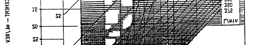
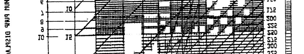
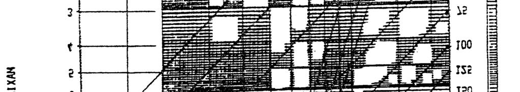

10 FIGURE 2. Maximum pump displacement vs pump speed. (metric unit) 10
11 Pressure pulsations. Pressure pulsations are the oscillations of the discharge pressure, occuring during nominally steady operating conditions, at a frequency equal to or higher than the pump drive shaft speed. The amplitude of pressure pulsations shall be determined by the test procedure of These pulsations shall not exceed ± 300 psi (± 2100 kpa) under any condition, or a pressure band specified by the detail pump specification. The pump shall be tested in the circuit which simulates the actual system in which the pump is to be installed, as defined in the detail pump specification. The system volume shall be simulated using tubing of the discharge line diameter. A tubing line length whose natural frequency is resonant with pulsation frequency shall be avoided Variable flow control. The pump shall incorporate flow control means which shall act to increase the flow of the pump from zero to its maximum full-flow value for any given operating speed as the discharge pressure is reduced from rated discharge pressure to maximum full-flow pressure and vice versa Response time. The response time of the pump shall be the time interval between the instant when an increase (or decrease) in discharge pressure change initiates; and the subsequent instant when the discharge pressure reaches its first maximum (or minimum) value. In figures 3 and 4, the time intervals T 1 and T 2 are the response times of the pump as a function of the system impedance. The oscillographic trace of discharge pressure versus time shall be employed as the criterion of movement of the flow control mechanism. All pump models when operating at rated inlet temperature at rated speed and in a circuit whose system impedance as specified in for response tests, shall have a response time of.050 seconds maximum unless otherwise specified in the detail pump specification Stability. The stability of the pump shall be the freedom from persistent or quasi/persistent oscillation or hunting" of the flow control mechanism at any frequency that can be traced to the pump flow control means. The oscillographic trace of discharge pressure versus time shall be employed as the criterion of the stability. All pump models, under any operating condition within the limits established in the detail pump specification and at any speed greater than 50 percent of rated speed, after being disturbed from steady-state operation by a change in flow demand or a change in pump speed, shall recover steady-state operation (other than permissible pressure pulsations as specified in ), within one second after initial response to that change in flow demand. When required by the contracting activity, the pump manufacturer shall provide pump data to permit the system designer to integrate pump dynamic performance into his complete pump and system analysis Maximum transient pressure. The maximum transient pressure shall be the peak value of the oscillographic trace of discharge pressure, made during operation of a pump, as specified in and measured as shown on figure 3. The maximum transient pressure, as determined in the transient pressure test specified in , shall not exceed 135 percent 11
12 of rated discharge pressure for systems up to 5000 psi (34,500 kpa) and 120 percent for systems above 5000 psi or as defined in the detail pump specification Depressurization. When it is a requirement of the detail specification that the pump be depressurized, either automatically or remotely as by an electrical signal, the repressurization control shall not, when deenergized, interfere with the normal operation of the variable flow control. The detail pump specification shall specify the requirements of qualification tests and quality conformance tests of the repressurization control. When full-flow repressurization is required, the detail pump specification shall identify the minimum and maximum operating pressure Balance. The moving parts of the hydraulic pump shall be balanced and the pump shall not vibrate in such a manner as to cause failure of any part in the pump or drive mechanism at speeds up to and required overspeed Adjustment. Means shall be provided to adjust the flow control mechanism to cause zero flow to occur at rated discharge pressure. This adjustment shall be preferably continuous, or acceptable in steps of less than one percent of rated discharge pressure over a minimum range of from 95 percent of rated pressure to 105 percent of overpressure. The adjustment means shall be capable of being positively locked, and it shall be possible to accomplish adjustment and locking by the application of standard hand tools. Where practicable, the design shall permit adjustment to be made while operating under full system pressure with negligible loss of fluid Safety wire sealing. Lead type safety wire sealing shall not be used Directionally critical components. Wherever practical, internal parts which are subject to malfunction and failure to operate due to reverse installation or rotated assembly shall have mechanical provisions to prevent improper installation or assembly. 3.4 Environmental requirements. In general, pumps shall be designed to operate, without limitations as to time, impairment of function or change in adjustment, under environmental conditions as specified in through Except as specifically directed herein, testing to demonstrate compliance with these requirements is not mandatory Altitude. Provided that inlet pressure is maintained to at least the rated value as specified in 3.3.4, pump performance shall not be affected by change of altitude Temperature. For purposes of design, it shall be asumed that the ambient temperature surrounding the pump shall be such that no heat is transferred to and from the pump except by normal circulation of the working fluid. 12
13 FIGURE 3. Typical pressure transient full flow to zero flow. 13
14 FIGURE 4 Typical pressure transient zero flow to full flow. 14
15 3.4.3 Vibration. Pumps shall be capable of withstanding vibrations excited by the driving means. For design and test purposes, torsional vibration excited by the driving means shall be considered negligible. As part of the qualification test, all pump models shall be subjected to the vibration tests specified in Acceleration. All pumps shall be designed to withstand sustained acceleration of 10g applied in any direction Atmospheric conditions. All pumps shall be designed to withstand continuous exposure, as installed in the application and either operating or non-operating, to salt spray as encountered in marine or coastal areas and to sand and dust as encountered in desert areas. If resistance to other matter is needed, these shall be identified in the detail pump specification. 3.5 Installation requirements Dimensions. Dimensions pertinent to the installation of pumps aircraft shall be specified on the manufacturer s installation drawing Weight. Both wet and dry weights shall be specified on the installation drawing Mounting. Unless otherwise specified in the detail pump specification, all pumps shall incorporate a standard mounting flange in accordance with one of the following standards: MS3330 through MS3334 design standards for flanges having bolt circle (BC) diameters 2.653, 5, 8, and Orientation. The case drain port of the pump shall be located at or near the top of the pump as it is installed on its drive pad. Reorientation of the pump due to vehicle attitude shall not affect pump operation Direction of rotation. The direction of rotation of the pump shall be clearly and permanently marked on an exposed surface of the pump housing Drive coupling and bushing A replaceable part of the pump assembly, incorporating a shear section, shall be interposed between the pump drive shaft and the driver such as an engine accessory drive shaft. The coupling shall be positively retained to the pump drive shaft. The interface between the coupling and the driver shall be as outlined in the detail pump specification. For interface splines that are not force-lubricated, the detail pump specification shall specify all material and dimensional aspects of a non-metallic spline bushing to protect the driver. The shear characteristics of the bushing shall be such that it does not fail before the coupling shear section, and shall be capable of transmitting, as a minimum, a 15
16 torque in excess of 3 times the maximum torque requirements of the pump Ports. Ports shall incorporate ring locked type boss fittings conforming to SAE-AS1300 for systems up to 5000 psi, and SAE-AS4201 for systems above 5000 psi, unless otherwise specified in the detail pump specification Structural strength. The structural design of the ports and of the affected sections of the pump housing shall be such as to withstand the application of a torque 2.5 times the maximum value specified in MS21344, resulting from the attachment or removal of fittings and hoses when installing or removing pumps during field maintenance, without permanent distortion or impairment of function Port markings. Inlet, outlet, and case drain ports shall be identified in accordance with MIL-STD-130 on each pump with clear and permanent markings. 3.6 Detail requirements, Material. Materials used shall conform to the applicable pump specifications and be compatible with the hydraulic fluid. The pump manufacturer s material specifications are acceptable provided they are approved by the contracting activity and contain provisions for adequate tests. The use of the pump manufacturer s specifications shall not constitute waiver of other applicable specifications Metals. All metals shall be compatible with the hydraulic fluid and applicable temperature, function, service, and storage conditions. Magnesium shall not be used. To minimize the corrosion of internal parts in fluids with chlorine levels over 100 ppm and water levels over 250 ppm, ferrous alloys shall have a chromium content of not less than 12 percent such as 440C and BG-42 or shall be protected against corrosion as specified in O-ring grooves for external seals shall not be considered as internal surfaces in constant contact with hydraulic fluid. The use of alternative materials and processes requires approval of the contracting activity. Such materials or processes shall be selected so as to provide the maximum degree of corrosion resistance consistent with the performance requirements Corrosion protection. Metals which do not inherently possess corrosion-resisting characteristics shall be protected to resist corrosion which may result from such conditions as dissimilar metal combinations, moisture, salt spray, or high temperature deterioration. Ferrous alloys requiring corrosion preventive treatment, and all copper alloys, except for parts having bearing surfaces, shall have an electrodeposited metallic coating selected from table III. Tin plating, cadmium plating, and zinc plating shall not be used for internal parts or parts where internal surfaces in contact with hydraulic fluid or exposed to its vapors and not where subject to abrasion. Where not indicated in the contract, selection of class and type of l6
17 coating are at the option of the manufacturer. Other coatings shall be used with the approval of the contracting activity. Unless otherwise specified in the contract, all aluminum alloys shall be anodized in accordance with MIL-A-8625, except that in the absence of abrasive conditions they shall be coated with chemical film in accordance with MIL-C The exceptions noted will be subject to the approval of the contracting activity Castings. Castings shall be of high quality, clean, sound, and free from cracks, blow holes, porosity, and other defects. Defects not materially affecting the quality of the castings shall be repaired at the foundry or during machining by peening, impregnation, welding, or other methods acceptable to the contracting activity. Inspection and repair of castings shall be governed by quality control techniques and shall be satisfactory to the contracting activity. When impregnated castings are used, they shall be in accordance with impregnation procedures and inspection requirements of MIL-STD-276. TABLE III. Metallic coatings Seals. For type I system pumps, static and dynamic seals shall be in accordance with MIL-P For type II system pumps, static and dynamic seals shall be in accordance with MIL-R Back-up rings shall be in accordance with MIL-R-8791/1 or MS Other seals and back-up rings necessary to demonstrate compliance with the requirements of this specification may be used with the approval of the contracting activity. All seal installation designs shall conform to MIL-H For type III system pumps, seals and back-up rings used shall be subject to approval of the contracting activity Identification of product. A nameplate conforming to MIL-P and the applicable MIL-P specification sheet as required by the detail specification shall be securely attached to the pump. It shall contain the following information, marked in accordance with MIL-STD-130 in the spaces provided. 17
18 PUMP, HYDRAULIC, VARIABLE FLOW, AIRCRAFT Detail pump specification no. Manufacturers part no (or identification) Manufacturers name or trademark Serial number Fluid Rating: Flow gpm or 1/m Pressure psi or kpa Speed rpm Any nameplate data required in addition to the above shall be specified in the detail pump specification Design and construction Lubrication. Except for the coupling shaft spline, the hydraulic pump shall be self-lubricated with no provisions for lubrication other than the circulating fluid Leakage. External leakage from the pump housing or from any static seal of sufficient magnitude to form a drop shall not be permitted except at the drive shaft seal, where the rates of leakage under specified operating conditions shall not exceed the values specified in Reliability. The pump shall have an upper test mean-time-betweenfailure, θ as defined in MIL-STD-781, of 2000 hours, at a discrimination ratio of (see ), and a decision risk of 10 percent (see 6.4.1), when operating duty cycle as specified in the detail pump specification Maintainability. The hydraulic pump shall be designed to meet the maintainability requirements as specified in the detail pump specification. Where possible, the pump shall include the following maintainability features. a. All wear surfaces shall be replaceable or repairable. b. Disconnects, mounting, and wiring provisions shall be designed to prevent erroneous connections. c. Components which are not functionally interchangeable shall not be physically interchangeable. d. The design shall permit line replacement of the unit or module using standard tools only. e. The design shall be such-that special or unique equipment is minimized for shop repair, overhaul, and checkout. 3.7 Workmanship. Pumps shall meet all design requirements and dimensional requirements of this specification and detail pump specification. Improper fabrication, loose materials, defective internal parts, damaged or 18
19 improperly assembled parts, peeling or chipping of plating or finish, galling of mating parts, nicks and burrs of metal parts shall be considered for rejection of the pump assembly. 4. QUALITY ASSURANCE PROVISIONS 4.1 Responsibility for inspection. Unless otherwise specified in the contract or purchase order, the contractor is responsible for the performance of all inspection requirements as specified herein. Except as otherwise specified in the contract or purchase order, the contractor may use his own or any other facilities suitable for the performance of the inspection requirements specified herein, unless disapproved by the Government. The Government reserves the right to perform any of the inspections set forth in this specification where such inspections are deemed necessary to ensure supplies and services conform to prescribed requirements Responsibility for compliance. All items shall meet all requirements of sections 3 and 5. The inspection set forth in this specification shall become a part of the contractor s overall inspection system or quality program. The absence of any inspection requirements in the specification shall not relieve the contractor of the responsibility of ensuring that all products or supplies submitted to the Government for acceptance comply with all requirements of the contract. Sampling inspection, as part of manufacturing operations, is an acceptable practice to ascertain conformance to requirements, however, this does not authorize submission of known defective material, either indicated or actual, nor does it commit the Government to accept defective material (see 6.3). 4.2 Classification of inspections. For the purpose of demonstrating pump compliance with this specification, MIL-H-8775, or MIL-H-8890, as applicable, and the detail pump specification, the following test program shall be performed: a. Qualification (see 4.3). b. Quality conformance (see 4.4). c. Reliability tests (see 4.5). 4.3 Qualification. The qualification tests are conducted to demonstrate conformance of the pump design to the requirements of this specification MIL-H-8775 or MIL-H-8890, as applicable, and with the detail pump specification to ensure their suitability for use in specific installations, and to verify the manufacturer s ability to produce the items Qualification approval procedure Similarity. A pump or portion thereof may be qualified because it is similar to a qualified product approved by a contracting activity. For similarity to apply, the new parts shall be functionally similar to those of the qualified product and the operating requirements for new product shall be no greater than those for the qualified me. A report substantiated by 19
20 drawings showing similarity to the qualified article shall be submitted in lieu of one containing actual test results (see 6.3) Qualification test report. A report of the tests performed and the result shall be submitted to the contracting activity, The report shall include full evaluation of the extent of compliance of the tested pumps to the specified requirements. The report shall include a full description of the manner in which the tests were performed including instrumentation description, schematic diagrams, photographs as appropriate, arid copies of the test data sheets. Hydraulic test circuits shall be described in complete detail for each test. A parts list of the pump shall accompany the report (see 6.3) Qualification tests. These tests shall consist of the following, performed in the order listed on one sample pump, or the same test performed on two sample pumps (A and B) on a selected basis as shown in table IV. The detail pump specification shall include any supplemental requirements, test methods, and number of test samples to ensure satisfactory operation and service life in the particular installation Qualification test methods. The hydraulic fluid used in all qualification tests shall be that specified in the detail specification. Unless otherwise specified in the detail pump specification, the required steady state test operating conditions shall be maintained within the following limits: a. Inlet temperature: -70 F to +110 F, ± 5 F (-56 C to +45 C, ±3 C) +111 F to +225 F, ±10 F (+46 C to +110 C, ±6 C) +226 F to +390 F, ±15 F (+111 C to +200 C, ±8 C) b. Inlet pressure within + 2 percent c. Pump shaft speed within ±2 percent d. Discharge pressure within ±2 percent e. Flow within ±2 percent Accuracy of the instrumentation for all tests shall be consistent with the measurement tolerances required Method of selection. The pump or pumps chosen for the qualification test shall be representative of those pumps to be produced in future production Quality conformance. The pumps selected for the test shall be subjected to a quality conformance inspection. Selected parts shall be checked for compliance with drawing requirements, and actual dimensions of critical features shall be recorded. After assembly of the pumps, quality conformance shall be conducted in accordance with section

21 TABLE IV. Qualification tests. * Performanced on either pump (A) or pump (B) Fluid immersion test. Where electrical components are a part of the pump assembly, they, as part of their qualification test, shall be separately subjected to a fluid immersion test prior to the start of the qualification test. This will consist of continuous immersion for 72 hours in the hydraulic fluid at rated temperature. After the 72-hour soak period, the component shall remain in the fluid at normal temperature until ready for further tests Proof pressure tests. The proof pressure test of shall be repeated after completing pump reassembly. 2 1
22 Calibration test. The pump flow rate and driving torque shall be determined at each of the following speeds; minimum operating speed, 25, 50, 75, 100 and 110 percent of rated speed. At each speed, flow and torque shall be recorded at the following pressures: 25, 50, 75, and 100 percent of maximum full-flow pressure and at 5 equally spaced increments of flow between maximum full-flow pressure and rated discharge pressure. Unless otherwise specified in the detail pump specifications, calibrations shall be recorded at the inlet condition specified in and flow measurements shall be taken in the line downstream of the load valve and corrected for fluid compressibility Pump inlet pressure. Regulate the pressure at the pump inlet port to the rated inlet pressure at full-flow and rated speed conditions Minimum operating speed. The speed shall be reduced below 25 percent of the rated speed to determine the speed below which the discharge flow or pressure becomes erratic. This point shall be recorded and designated the minimum operating speed for that condition Maximum pressure, response time, and pressure pulsations. Pressure transducer and recording equipment shall be used to provide an oscillographic record or its equivalent of the pressure to time function of the pump and its hydraulic circuit through the transient and steady state periods described in the following three tests. The pressure transducer and recording equipment shall be capable of static calibration with repetitive accuracy of 5 percent of rated pressure and readability of 3 percent of rated pressure. It shall be considered essential that the dynamic calibration of the equipment is valid for the dynamic conditions. The pressure transducer shall be located in the pump discharge line as close as possible to the outlet fitting. Tests shall be conducted at rated conditions unless noted otherwise below, or in the detail pump specification System impedance Response time. The system impedance of the test circuit when determining pump response shall be such that when the pump is operating at rated speed, maximum full-flow pressure, and rated inlet temperature, the rate of pump discharge pressure rise, when the flow in the system is suddenly stopped (the minimum rise rate of the maximum slope of pressure rise) shall be 50,000 psi/sec (345,000 kpa/see). This will be as calculated from system volume, pump rated flow, and fluid bulk modulus at rated temperature and rated discharge pressure All other tests. The system impedance of the test circuit when determining maximum pressure, pressure pulsations, stability, and the remaining qualification tests, shall be specified in the detail pump specification. Both inlet circuit and high pressure circuit shall simulate the application. 22
23 Maximum pressure test. The test circuit specified in shall be used. Flow changes shall be initiated by a solenoid operated valve with an actuation response time second or less, or as specified in the detail pump specification. As the test pump is cycled between steady state maximum full-flow pressure and steady state rated discharge pressure, an oscillographic record of the pressure-to-time function through the transient period shall be made in each direction. The test shall be run at 50 percent and 100 percent of rated pump speed. Air entrainment in the hydraulic fluid shall be at a minimum. Unless otherwise specified in the detail pump specification, the peak pressure transient as measured on the above record shall not exceed the limits of the maximum transient pressure (see ) Response time. With the test circuit specified in 4.3, , and load valves set at a flow condition equivalent to maximum full-flow pressure at each of the test speeds, the solenoid valve, which changes discharge line from full open to full closed, or vice versa, shall then be used to execute the test. The pump shall be run at 50, 75, and 100 percent of rated speed or as specified in the detail pump specification. With the solenoid valve open and the test pump operating at steady state maximum full-flow pressure, an oscillographic record shall be made of the pressuretime function through the transient period associated with the closing of the solenoid valve and establishment of steady state rated discharge pressure. Typically, this record shall be similar to figure 3, and the response time, T1, as indicated thereon, shall not exceed seconds at 100 percent of rated speed. At 50 and 75 percent of rated speed, T1 shall not exceed the value specified in the detail pump specification. The response time T2 for the change from rated discharge pressure to maximum full-flow pressure shall be recorded and, as indicated on figure 4, shall not exceed seconds at 100 percent rated speed or as specified in the detail pump specification. At 50 and 75 percent of rated speed, the response time T2 shall not exceed the value specified in the detail pump specification. Check the response time for small incremental changes of flow as follows: Introduce a parallel flow path which includes an orifice and a downstream solenoid valve with second response or as specified in the detail pump specification. This orifice shall be adjusted to pass 5 percent of maximum full-flow and the main load throttling valve shall be adjusted to pass 90 percent of maximum full-flow for each of the three pump speed settings. Check response time at each speed setting when the small flow path solenoid is opened and closed with the main flow path solenoid valve both opened and closed. The response time at rated speed shall not exceed seconds Pressure pulsations. The test circuit specified in shall be equipped with a dynamic pressure transducer of zero volume and a frequency response of 20 HZ to 100 khz. With pump at rated discharge pressure, vary the speed from 50 to 100 percent of rated speed at a rate of change not exceeding 100 RPM per second. During this period an oscillographic record of the pulsation pattern shall be made. This speed scan shall be repeated at 25, 50, 75 and 100 percent of rated flow. Values of pressure pulsation shall not exceed the limits specified in
24 Pressure control and stability. The calibration tests of shall be extended to check pump stability and discharge pressure for the fluid temperature range as outlined in the detail pump specification Heat rejection. The rate of heat rejection at specified conditions shall be considered equal to the difference between the input and output horsepower of the pump at those conditions. Output power of the pump may be calculated based on flow measurements in the low pressure side of the discharge line provided compensation is made for fluid compressibility in calculating output power. To determine the rate of heat rejection, the pump shall be run at rated speed and rated inlet temperature, and the input and output power determined at rated discharge pressure, maximum full-flow pressure, and at least 2 additional flow points between those values. The maximum acceptable value of heat rejection rate at specified operating conditions shall be specified in the detail pump specification Vibration tests Test pump mounting orientation. The test pump shall be mounted on a vibration generating mechanism successively in each of at least 3 positions. All of the testing specified shall be performed in each of the mounting positions. One of these mounting positions shall be such that the direction of vibratory motion shall be parallel to the shaft axis of the pump. Another mounting position if and when practicable, shall be such that the direction of vibratory motion shall be parallel to the axis of the compensating mechanism. When the pump is equipped with an electrical repressurization device, an additional mounting position shall be such that the direction of vibratory motion is parallel to the electric repressurizing valve (EDV) mechanism Resonant frequency vibration. Resonant frequencies shall be searched according to the double amplitude and frequency charts of MIL-STD-810, Method Applicable procedures and test values shall be specified in the detail pump specification Cyclic frequency vibration. Upon completion of the resonant frequency vibration, a cycling vibration shall be imposed in accordance with MIL-STD-810, Method Applicable procedures and test values shall be specified in the detail specification Other vibration tests. The detail specification will require other vibration tests to be performed when a particular installation imposes severe environmental conditions peculiar to its system requirements Pump operation. Throughout the above vibration tests the pump shall be operated in the test circuit of Fluid inlet temperature shall be 140 F ±40 F (60 C ±22 C) regardless of the rated temperature of the pump being tested, and ambient temperatures shall be maintained at room ambient conditions. The pump discharge shall be continuously cycled between zero flow and approximately 50 percent of rated 24
25 flow at approximately 5 cycles per minute (cpm) with a valve response time of 0.5 second maximum. Where the pump is equipped with a repressurizing means, cycle between pressurized and repressurized modes as required by the detail pump specification Low temperature and thermal cycle test. All low temperature requirements apply equally to the pump body and hydraulic fluid. The ambient environment temperature may vary ±20 F (±1l C). After at least 18 hours at the minimum inlet temperature specified in the detail pump specification [or -65 F ±5 F (-54 C ±3 C) in the absence of a value in the detail pump specification] the pump shall be started and uniformly accelerated to 50 percent of rated speed in not more than 10 seconds, unless otherwise specified in the detail pump specification. Five runs shall be made with the outlet pressure as low as practicable and the inlet pressure as specified in the detail pump specification. The rated speed shall be reached within 20 seconds after start-up. When rated speed has been reached, it shall be maintained for at least 10 seconds; observations shall indicate whether the pump displaces fluid through the hydraulic system. Then 5 starts and runs shall be made, with the pump discharge line terminating in a load valve which is set to pass fluid at 90 percent of maximum full-flow pressure at room temperature. The pump shall be allowed to run until rated fluid temperature is reached after each of these five starts. In addition, five starts shall be made with the pump discharge line completely closed so that the pump shall operate at rated discharge pressure. Throughout these tests, after each run, the pump and fluid shall be allowed to stand idle long enough for them to be restored to the above soaking temperature before starting the next run. When the pump includes a repressurization device that is used as an engine starting aid, the device shall be activated during starts and deactivated as specified in the detail pump specification Thermal shock. To conduct the thermal shock cycle, the hydraulic pump and fluid shall be cooled to -65 F (-54 C) or a temperature specified in the detail pump specification. The hydraulic reservoir temperature shall be maintained at rated temperature and contain a volume of fluid equal to that in the aircraft system or as specified in the detail pump specification. The pump shall be started and brought up to rated speed in a time interval specified in the detail pump specification. Discharge pressure shall be set to cause the pump to deliver rated flow or as specified in the detail pump specification. The pump shall not malfunction Endurance test. A sample pump shall complete a 2000 hour endurance test as outlined in table V for type I and type II systems. For type III systems, the test shall be outlined in the detail pump specification. Unless otherwise specified in the detail pump specification, the following test conditions apply to table V: a. Rated inlet pressure (see 3.3.4). b. Rated case drain pressure (see ). c. Inlet fluid temperature shall be 180 F ±10 F (80 C ±5 C) except: (1) Phase 2 and 5 shall each include at least 200 hours at rated 25
26 temperature. (2) Phase 4 shall include at least 100 hours at rated temperature (see ). (3) Phases 7 and 8 shall be conducted with the compensator as adjusted for overpressure in phase 6 (see ). TABLE V. Endurance test conditions. The following notes apply to table V: 1/ 95 percent of maximum full-flow pressure. 2/ Outlet pressure shall be adjusted to provide stipulated flow. 3/ A time tolerance of ±1 percent of the test hours in each phase is permissible for ease of test implementation. The total test hours of all phases combined shall be 2000 hours Filtration for endurance test. The hydraulic fluid to be used in the endurance test system shall be passed through a 5-micron absolute filter before entering the test system. Filter elements in accordance with MIL-F-8815, either 5-micron absolute or l5-micron absolute as specified in the detail pump specification, shall be installed in the pump inlet, outlet, and case drain or cooling port lines throughout the endurance test Filter check. At intervals not to exceed 100 ±16 hours during the endurance test, pump condition shall be monitored by means of 26
Downloaded from
 December 20, 1989 TO SUPERSEDE W-F-408D 30 March 1984 FEDERAL SPECIFICATION FITTINGS FOR CONDUIT, METAL, RIGID (THICK-WALL AND THIN-WALL (EMT) TYPE) This specification is approved by the Commissioner.
European Aviation Safety Agency. European Technical Standard Order. ED Decision 2016/013/R Annex II. Subject: FUEL DRAIN VALVES
 European Aviation Safety Agency Date: 5.8.2016 European Technical Standard Order Subject: FUEL DRAIN VALVES 1 Applicability This ETSO provides the requirements which Fuel Drain Valves that are designed
PERFORMANCE SPECIFICATION COOLERS, LUBRICATING OIL, AIRCRAFT, GENERAL SPECIFICATION FOR
 INCH-POUND 06 May 2013 SUPERSEDING MIL-PRF-25478C 29 December 1997 PERFORMANCE SPECIFICATION COOLERS, LUBRICATING OIL, AIRCRAFT, GENERAL SPECIFICATION FOR This specification is approved for use by all
PERFORMANCE SPECIFICATION COOLERS, LUBRICATING OIL, AIRCRAFT, GENERAL SPECIFICATION FOR
 I INCH-POUND 29 December 1997 SUPERSEDING MIL-C-25478B(USAF) 28 March 1995 PERFORMANCE SPECIFICATION COOLERS, LUBRICATING OIL, AIRCRAFT, GENERAL SPECIFICATION FOR This specification is approved for use
INCH-POUND MIL-DTL-24211D 25 February 2016 SUPERSEDING MIL-DTL-24211C 9 February 2011 DETAIL SPECIFICATION
 DETAIL SPECIFICATION INCH-POUND MIL-DTL-24211D 25 February 2016 SUPERSEDING MIL-DTL-24211C 9 February 2011 GASKETS, WAVEGUIDE FLANGE GENERAL SPECIFICATION FOR 1. SCOPE This specification is approved for
UNITED STATES DEPARTMENT OF AGRICULTURE FOREST SERVICE STANDARD FOR SPARK ARRESTERS FOR INTERNAL COMBUSTION ENGINES
 Standard 00-c September Superseding 00-b July UNITED STATES DEPARTMENT OF AGRICULTURE FOREST SERVICE STANDARD FOR SPARK ARRESTERS FOR INTERNAL COMBUSTION ENGINES. SCOPE... Scope. This standard establishes
MILITARY SPECIFICATION LUBRICATING OIL, VACUUM PUMP, MECHANICAL
 INCH-POUND MIL-DTL-83767C 24 September 2007 SUPERSEDING MIL-L-83767B 8 February 1980 MILITARY SPECIFICATION LUBRICATING OIL, VACUUM PUMP, MECHANICAL Reactivated after 24 September 2007 and may be used
DETAIL SPECIFICATION GASKETS, WAVEGUIDE FLANGE GENERAL SPECIFICATION FOR
 INCH-POUND 25 November 1998 SUPERSEDING MIL-G-24211 28 MARCH 1966 DETAIL SPECIFICATION GASKETS, WAVEGUIDE FLANGE GENERAL SPECIFICATION FOR This specification is approved for use by all Departments and
DEPARTMENT OF DEFENSE STANDARD PRACTICE IDENTIFICATION CODING AND APPLICATION OF HOOKUP AND LEAD WIRE
 NOTICE OF CHANGE INCH-POUND MIL-STD-681D NOTICE 1 19 June 2000 DEPARTMENT OF DEFENSE STANDARD PRACTICE IDENTIFICATION CODING AND APPLICATION OF HOOKUP AND LEAD WIRE TO ALL HOLDERS OF MIL-STD-681D: 1. THE
[INCH-POUND] A-A December 1999 SUPERSEDING MIL-C-4109F 31 October 1986
![[INCH-POUND] A-A December 1999 SUPERSEDING MIL-C-4109F 31 October 1986](/thumbs/90/102223285.jpg "[INCH-POUND] A-A December 1999 SUPERSEDING MIL-C-4109F 31 October 1986") [INCH-POUND] 30 December 1999 SUPERSEDING MIL-C-4109F 31 October 1986 COMMERCIAL ITEM DESCRIPTION COUPLING HALVES, QUICK-DISCONNECT The General Services Administration has authorized the use of this commercial
[INCH-POUND] 30 December 1999 SUPERSEDING MIL-C-4109F 31 October 1986 COMMERCIAL ITEM DESCRIPTION COUPLING HALVES, QUICK-DISCONNECT The General Services Administration has authorized the use of this commercial
PERFORMANCE SPECIFICATION ACTUATORS: AERONAUTICAL LINEAR UTILITY, HYDRAULIC, GENERAL SPECIFICATION FOR
 INCH-POUND 24 May 2013 SUPERSEDING MIL-PRF-5503F 26 June 1998 PERFORMANCE SPECIFICATION ACTUATORS: AERONAUTICAL LINEAR UTILITY, HYDRAULIC, GENERAL SPECIFICATION FOR This specification is approved for use
MILITARY SPECIFICATION MICROCIRCUITS, LINEAR, CMOS, ANALOG SWITCH WITH DRIVER, MONOLITHIC SILICON
 INCH-POUND 4 February 2004 SUPERSEDING MIL-M-38510/116 16 April 1980 MILITARY SPECIFICATION MICROCIRCUITS, LINEAR, CMOS, ANALOG SWITCH WITH DRIVER, MONOLITHIC SILICON This specification is approved for
MILITARY SPECIFICATION MOUNT, TELESCOPE AND QUADRANT: M172
 MILITARY SPECIFICATION MOUNT, TELESCOPE AND QUADRANT: M172 30 MARCH 1990 SUPERSEDING MIL-M-48559(MU) 12 September 1975 This specification is approved for use by the U.S. Army Armament, Munitions and-chemical
PERFORMANCE SPECIFICATION ACTUATOR, LINEAR, ELECTROMECHANICAL
 INCH-POUND PERFORMANCE SPECIFICATION 17 September 2015 SUPERSEDING MIL-A-85046(AS) 7 September 1976 ACTUATOR, LINEAR, ELECTROMECHANICAL This specification is approved for use by the Naval Air Systems Command
FEDERAL SPECIFICATION TRUCKS, HAND, TWO WHEELED
 INCH-POUND KKK T 683F 15 December 2010 SUPERSEDING KKK T 683E w/amendment 1 11 July 2005 FEDERAL SPECIFICATION TRUCKS, HAND, TWO WHEELED The General Services Administration has authorized the use of this
PERFORMANCE SPECIFICATION SHEET SWITCHES, SENSITIVE, PLUNGER, 10 AMPERES 2PDT AND 7 AMPERES 4PDT, RESILIENT SEAL
 INCH-POUND MIL-PRF-8805/100G 6 December 2012 SUPERSEDING MIL-PRF-8805/100F 4 October 2004 PERFORMANCE SPECIFICATION SHEET SWITCHES, SENSITIVE, PLUNGER, 10 AMPERES 2PDT AND 7 AMPERES 4PDT, RESILIENT SEAL
QQ-W-343F 19 November 1990 (TO SUPERSEDE) QQ-W-343-E November 13, 1981 FEDERAL SPECIFICATION WIRE, ELECTRICAL, COPPER (UNINSULATED)
 QQ-W-343-E November 13, 1981 FEDERAL SPECIFICATION WIRE, ELECTRICAL, COPPER (UNINSULATED)") 19 November 1990 (TO SUPERSEDE) QQ-W-343-E November 13, 1981 FEDERAL SPECIFICATION WIRE, ELECTRICAL, COPPER (UNINSULATED) 1. SCOPE AND CLASSIFICATION 1.1 Scope. This specification covers solid, bunch-stranded,
19 November 1990 (TO SUPERSEDE) QQ-W-343-E November 13, 1981 FEDERAL SPECIFICATION WIRE, ELECTRICAL, COPPER (UNINSULATED) 1. SCOPE AND CLASSIFICATION 1.1 Scope. This specification covers solid, bunch-stranded,
MATERIAL AND EQUIPMENT STANDARD FOR ABRASIVE AIR BLASTING MACHINE ORIGINAL EDITION MARCH 1996
 MATERIAL AND EQUIPMENT STANDARD FOR ABRASIVE AIR BLASTING MACHINE ORIGINAL EDITION MARCH 1996 This standard specification is reviewed and updated by the relevant technical committee on Oct. 2003. The approved
PERFORMANCE SPECIFICATION ACTUATORS: AERONAUTICAL LINEAR UTILITY, HYDRAULIC, GENERAL SPECIFICATION FOR
 INCH-POUND 26 June 1998 SUPERSEDING MIL-A-5503E 10 January 1986 PERFORMANCE SPECIFICATION ACTUATORS: AERONAUTICAL LINEAR UTILITY, HYDRAULIC, GENERAL SPECIFICATION FOR This specification is approved for
PROCUREMENT SPECIFICATION FOR CNP19 CHERRY RIVETLESS NUT PLATE
 PROCUREMENT SPECIFICATION NUMBER PRINTED COPIES OF THIS DOCUMENT ARE CONSIDERED REFERENCE UNLESS OTHERWISE STAMPED IN RED INK. PROCUREMENT SPECIFICATION FOR CNP19 CHERRY RIVETLESS NUT PLATE Authorizing
UNITED STATES COAST GUARD OCEAN ENGINEERING DIVISION WASHINGTON, D.C. JANUARY 2011 SPECIFICATION FOR THE MANUFACTURE
 UNITED STATES COAST GUARD OCEAN ENGINEERING DIVISION WASHINGTON, D.C. JANUARY 2011 SPECIFICATION FOR THE MANUFACTURE OF OPEN LINK, WELDED STEEL CHAIN AND BRIDLES SPECIFICATION NO. 377 REVISION L 1. SCOPE
REVISIONS SYMBOL DESCRIPTION DATE APPROVAL
 REVISIONS SYMBOL DESCRIPTION DATE APPROVAL L Revised per RN A-203. 2/23/16 JS K Revised per RN A-191 12/29/14 JS J Revised per RN A-183 4/25/13 JS I Revised per RN A-170. 7/15/11 JS H Revised per RN A-151.
DETAIL SPECIFICATION SHEET DISK, VALVE. Inactive for new design after 15 October 1998.
 INCH-POUND MS29521H 23 September 2015 SUPERSEDING MS29521G 7 April 2009 DETAIL SPECIFICATION SHEET DISK, VALVE Inactive for new design after 15 October 1998. This specification is approved for use by all
Laboratory Evaluation Report for: Backflow Preventer for Beverage Dispensing Equipment
 American Society of Sanitary Engineering Seal (Certification) Program Laboratory Evaluation Report for: Backflow Preventer for Beverage Dispensing Equipment Tested under ASSE Standard 1022 ASSE: 2003 ANSI:
MM-L-751H August 13, 1970 SUPERSEDING Int. Fed. Spec. MM-L-00751G(Army-ME) July 3, 1967 and Fed. Spec. MM-L-751C May 20, 1942 FEDERAL SPECIFICATION
 July 3, 1967 and Fed. Spec. MM-L-751C May 20, 1942 FEDERAL SPECIFICATION") MM-L-751H August 13, 1970 SUPERSEDING Int. Fed. Spec. MM-L-00751G(Army-ME) July 3, 1967 and Fed. Spec. MM-L-751C May 20, 1942 FEDERAL SPECIFICATION LUMBER; SOFTWOOD This specification was approved by the
MM-L-751H August 13, 1970 SUPERSEDING Int. Fed. Spec. MM-L-00751G(Army-ME) July 3, 1967 and Fed. Spec. MM-L-751C May 20, 1942 FEDERAL SPECIFICATION LUMBER; SOFTWOOD This specification was approved by the
SM1206 Series. Overload Interrupt Time (Second) Nominal Rating - Note 2. Cold Resistance (Ohm) Note 1. Maximum I 2 T (Ampere 2 Second) Nominal Rating
 Nominal Rating - Note 2. Cold Resistance (Ohm) Note 1. Maximum I 2 T (Ampere 2 Second) Nominal Rating") SM1206 Series Part Numbering System SM1206-32 - 1.0 Fuse Type Voltage Amp Part Number/Rating Cold Resistance (Ohm) Note 1 Overload Interrupt Time (Second) Nominal Rating - Note 2 Maximum I 2 T (Ampere
SM1206 Series Part Numbering System SM1206-32 - 1.0 Fuse Type Voltage Amp Part Number/Rating Cold Resistance (Ohm) Note 1 Overload Interrupt Time (Second) Nominal Rating - Note 2 Maximum I 2 T (Ampere
COMMERCIAL ITEM DESCRIPTION HOSE AND HOSE ASSEMBLIES, NONMETALLIC SPRAY
 [INCH-POUND] A-A-59613 August 16, 2001 SUPERSEDING ZZ-H-521F May 28, 1993 COMMERCIAL ITEM DESCRIPTION HOSE AND HOSE ASSEMBLIES, NONMETALLIC SPRAY The General Services Administration has authorized the
COMMERCIAL ITEM DESCRIPTION CLAMPS, HOSE
 INCH-POUND 7 JUNE 2006 SUPERSEDING A-A-52506B 16 AUGUST 1996 COMMERCIAL ITEM DESCRIPTION CLAMPS, HOSE The General Services Administration has authorized the use of this Commercial Item Description (CID)
QQ-A-250/11F August SUPERSEDING QQ-A-250/GEN. August 27, 1971 FEDERAL SPECIFICATION SHEET ALUMINUM ALLOY 6061, PLATE AND SHEET
 August 3 1982 SUPERSEDING QQ-A-250/11E August 27, 1971 FEDERAL SPECIFICATION SHEET ALUMINUM ALLOY 6061, PLATE AND SHEET This specification is approved by the Commissioner, Federal Supply Service, General
Style 234 Restrained Flexible Single-Gasket Coupling. System No. Submitted By Spec Sect Para Location Date Approved Date
 Victaulic Bolted Split-Sleeve Products (VBSP) Style 234 carbon steel couplings (formerly Depend-O-Lok Air/FluidMaster) are single-arch couplings that are commonly used in buried or exposed steel pipe applications
SFI SPECIFICATION 28.1 EFFECTIVE: AUGUST 25, 2017 *
 SFI SPECIFICATION 28.1 EFFECTIVE: AUGUST 25, 2017 * PRODUCT: Polymer (Foam-Filled) Fuel Cells 1.0 GENERAL INFORMATION 1.1 This SFI Specification establishes uniform test procedures and minimum standards
ÚÄÄÄÄÄÄÄÄÄÄ ÚÄÄÄÄÄÄÄÄÄÄ ³ METRIC ³ ÀÄÄÄÄÄÄÄÄÄÄÙ TT-T-306E May 28, 1993 SUPERSEDING TT-T-306D December 31, 1992 FEDERAL SPECIFICATION
 ÚÄÄÄÄÄÄÄÄÄÄ ÚÄÄÄÄÄÄÄÄÄÄ ³ METRIC ³ ÀÄÄÄÄÄÄÄÄÄÄÙ May 28, 1993 SUPERSEDING TT-T-306D December 31, 1992 FEDERAL SPECIFICATION THINNER, SYNTHETIC RESIN ENAMELS This specification has been approved by the Commissioner,
DETAIL SPECIFICATION SHEET
 METRIC MIL-DTL-38999/31E 12 March 2014 SUPERSEDING MIL-DTL-38999/31D 19 April 2002 DETAIL SPECIFICATION SHEET CONNECTORS, ELECTRICAL, CIRCULAR, THREADED, PLUG, LANYARD RELEASE, FAIL-SAFE, REMOVABLE CRIMP
COMMERCIAL ITEM DESCRIPTION PINTLE ASSEMBLY, TOWING, MANUAL RELEASE, , AND LBS CAPACITY
 [INCH-POUND] July 30, 1996 SUPERSEDING (see 7.5) COMMERCIAL ITEM DESCRIPTION PINTLE ASSEMBLY, TOWING, MANUAL RELEASE, 18 000, 40 000 AND 100 000 LBS CAPACITY The General Services Administration has authorized
SPECIFICATIONS - DETAILED PROVISIONS Section Vertical Hollowshaft Electric Motors C O N T E N T S
 Revised 04/14/2016 SPECIFICATIONS - DETAILED PROVISIONS Section 16151 - Vertical Hollowshaft Electric Motors C O N T E N T S PART 1 - GENERAL... 1 1.01 SCOPE... 1 1.02 SPECIFIC PROJECT REQUIREMENTS...
ELECTRICAL POWER, DIRECT CURRENT, SPACE VEHICLE DESIGN REQUIREMENTS
 MIL-STD-1539 (USAF) 1 AUGUST 1973 MILITARY STANDARD ELECTRICAL POWER, DIRECT CURRENT, SPACE VEHICLE DESIGN REQUIREMENTS FSC 1810 Electrical Power, Direct Current, Space Vehicle Design Requirements MIL-STD-1539
³ NOTICE OF³ ³INCH-POUND³. NOTICE 1 4 March 1991 MILITARY SPECIFICATION
 ÚÄÄÄÄÄÄÄÄÄÄ ÚÄÄÄÄÄÄÄÄÄÄ ³ NOTICE OF³ ³INCH-POUND³ ³VALIDATION³ ÀÄÄÄÄÄÄÄÄÄÄÙ ÀÄÄÄÄÄÄÄÄÄÄÙ NOTICE 1 4 March 1991 MILITARY SPECIFICATION INSTRUMENT AUXILIARIES, ELECTRICAL MEASURING: SHUNTS, RESISTORS, AND
SPECIFICATION SHEET P700L CURRENT LIMITING FUSE SURFACE MOUNT MODEL
 11525 Sorrento Valley Rd. San Diego, California 92121 (858) 481-0210 SPECIFICATION SHEET P700L CURRENT LIMITING FUSE SURFACE MOUNT MODEL REVISION: A B C D E F G H J DATE: 10/95 2/96 2/00 10/95 2/96 10/98
PERFORMANCE SPECIFICATION SHEET
 INCH-POUND MIL-PRF-83536/15A 12 July 2004 SUPERSEDING MIL-PRF-83536/15 27 March 1992 PERFORMANCE SPECIFICATION SHEET RELAYS, ELECTROMAGNETIC, ESTABLISHED RELIABILITY, 4PDT, LOW LEVEL TO 10 AMPERES, PERMANENT
Cold Resistance (Ohm) Note 1
 Note 1") P700L Series Part Numbering System P700L - 72-1.0 Fuse Type Voltage Amp Part Number/Rating Cold Resistance (Ohm) Note 1 Overload Interrupt Time (Second) Nominal Rating - Note 2/3 Maximum I 2 T (Ampere
P700L Series Part Numbering System P700L - 72-1.0 Fuse Type Voltage Amp Part Number/Rating Cold Resistance (Ohm) Note 1 Overload Interrupt Time (Second) Nominal Rating - Note 2/3 Maximum I 2 T (Ampere
COMMERCIAL ITEM DESCRIPTION BEARING, BALL, ANNULAR, SINGLE ROW, RADIAL, NON-FILLING SLOT, DIMENSION SERIES 02
 METRIC A-A-59584C 15 September 2008 SUPERSEDING A-A-59584B 23 September 2003 COMMERCIAL ITEM DESCRIPTION BEARING, BALL, ANNULAR, SINGLE ROW, RADIAL, NON-FILLING SLOT, DIMENSION SERIES 02 The General Services
Downloaded from
 [INCH-POUND] 28 April, 1995 SUPERSEDING W-C-596F/GEN 24 June, 1983 FEDERAL SPECIFICATION CONNECTOR, ELECTRICAL, POWER, GENERAL SPECIFICATION FOR The General Services Administration has authorized the use
UNITED STATES DEPARTMENT OF AGRICULTURE FOREST SERVICE STANDARD FOR SPARK ARRESTERS. FOR INTERNAL COMBUSTION ENGINEs
 Standard 5100-1d February 2013 Superseding 5100-1c September 1997 UNITED STATES DEPARTMENT OF AGRICULTURE FOREST SERVICE STANDARD FOR SPARK ARRESTERS FOR INTERNAL COMBUSTION ENGINEs Beneficial comments
COMMERCIAL ITEM DESCRIPTION BEARING, BALL, ANNULAR, SINGLE ROW, RADIAL, NON-FILLING SLOT, DIMENSION SERIES 03
 METRIC A-A-59585C 15 September 2008 SUPERSEDING A-A-59585B 23 September 2003 COMMERCIAL ITEM DESCRIPTION BEARING, BALL, ANNULAR, SINGLE ROW, RADIAL, NON-FILLING SLOT, DIMENSION SERIES 03 The General Services
SECTION METERS AND GAGES FOR HVAC PIPING
 PART 1 GENERAL 1.1 RELATED DOCUMENTS A. Drawings and general provisions of the Contract, including General and Supplementary Conditions Specification Sections, apply to this Section. 1.2 SUMMARY A. This
PERFORMANCE SPECIFICATION GREASE, AIRCRAFT, GENERAL PURPOSE, WIDE TEMPERATURE RANGE, NATO CODE G-395
 METRIC 24 January 2005 SUPERSEDING MIL-PRF-81322F 21 July 1998 PERFORMANCE SPECIFICATION GREASE, AIRCRAFT, GENERAL PURPOSE, WIDE TEMPERATURE RANGE, NATO CODE G-395 This specification is approved for use
SFI SPECIFICATION 35.2 EFFECTIVE: DECEMBER 29, 2014 *
 SFI SPECIFICATION 35.2 EFFECTIVE: DECEMBER 29, 2014 * PRODUCT: Heavy Duty Stock Car Steel Wheels 1.0 GENERAL INFORMATION 1.1 This SFI Specification establishes uniform test procedures and minimum standards
American Society of Sanitary Engineering PRODUCT (SEAL) LISTING PROGRAM
 LISTING PROGRAM") American Society of Sanitary Engineering PRODUCT (SEAL) LISTING PROGRAM ASSE STANDARD #1012 - REVISED: 2009 Backflow Preventers with an Intermediate Atmospheric Vent Separate, complete laboratory evaluation
American Society of Sanitary Engineering PRODUCT (SEAL) LISTING PROGRAM ASSE STANDARD #1012 - REVISED: 2009 Backflow Preventers with an Intermediate Atmospheric Vent Separate, complete laboratory evaluation
PERFORMANCE SPECIFICATION GREASE, AUTOMOTIVE AND ARTILLERY
 NOT MEASUREMENT SENSITIVE w/ 26 September 2012 SUPERSEDING 30 September 2008 PERFORMANCE SPECIFICATION GREASE, AUTOMOTIVE AND ARTILLERY This specification is approved for use by all Departments and Agencies
Laboratory Evaluation Report for: Laboratory Faucet Backflow Preventer
 American Society of Sanitary Engineering Seal (Certification) Program Laboratory Evaluation Report for: Laboratory Faucet Backflow Preventer Tested under ASSE Standard 1035 Revised: April, 2008 Laboratory
GG-W-00101c (VA-MED) February 21, 1965 INTERIM REVISION OF FED. SPEC. GG-W-101B September 25, 1957 INTERIM FEDERAL SPECIFICATION
 February 21, 1965 INTERIM REVISION OF FED. SPEC. GG-W-101B September 25, 1957 INTERIM FEDERAL SPECIFICATION") (VA-MED) February 21, 1965 INTERIM REVISION OF FED. SPEC. GG-W-101B September 25, 1957 INTERIM FEDERAL SPECIFICATION WASHERS, BEDPAN AND URINAL This Interim Federal Specification was developed by Veterans
(VA-MED) February 21, 1965 INTERIM REVISION OF FED. SPEC. GG-W-101B September 25, 1957 INTERIM FEDERAL SPECIFICATION WASHERS, BEDPAN AND URINAL This Interim Federal Specification was developed by Veterans
FEDERAL SPECIFICATION ETHER, PETROLEUM; TECHNICAL GRADE. 1.1 Scope. This specification covers technical grade petroleum ether to be used as a solvent.
 METRIC 4 May 2015 SUPERSEDING O-E-751C 10 January 2003 FEDERAL SPECIFICATION ETHER, PETROLEUM; TECHNICAL GRADE The General Services Administration has authorized the use of this federal specification by
PERFORMANCE SPECIFICATION SHEET SWITCHES, SENSITIVE, 10 AMPERES AND LOW LEVEL, UNSEALED
 INCH-POUND 2 January 201 SUPERSEDING 1 May 200 PERFORMANCE SPECIFICATION SHEET SWITCHES, SENSITIVE, AMPERES AND LOW LEVEL, UNSEALED This specification is approved for use by all Departments and Agencies
DEPARTMENT OF DEFENSE INTERFACE STANDARD
 INCH-POUND MIL-STD-1560C 23 January 2017 SUPERSEDING MIL-STD-1560C 11 February 2015 DEPARTMENT OF DEFENSE INTERFACE STANDARD INSERT ARRANGEMENTS FOR MIL-DTL-38999, MIL-DTL-27599, AND SAE-AS29600 SERIES
DETAIL SPECIFICATION HOSE, SYNTHETIC RUBBER - HYDRAULIC FLUID, FUEL, AND OIL RESISTANT
 INCH-POUND 16 April 2007 SUPERSEDING MIL-DTL-8794E 22 September 2000 DETAIL SPECIFICATION HOSE, SYNTHETIC RUBBER - HYDRAULIC FLUID, FUEL, AND OIL RESISTANT This specification is approved for use by all
PERFORMANCE SPECIFICATION LUBRICATING OIL, JET ENGINE
 INCH-POUND 12 December 2014 SUPERSEDING MIL-PRF-6081D w/amendment 1 30 January 2009 PERFORMANCE SPECIFICATION LUBRICATING OIL, JET ENGINE This specification is approved for use by all Departments and Agencies
COMPETITIVE INITIATIVE AVIATION FUEL RECLAMATION SYSTEM TECHNICAL SPECIFICATION
 1.0 SCOPE COMPETITIVE INITIATIVE AVIATION FUEL RECLAMATION SYSTEM TECHNICAL SPECIFICATION A system brand name or equal to Filterdyne Filtration Systems, Inc. Fuel Reclaim System Model F-111 Special, as
RULE 448 GASOLINE TRANSFER INTO STATIONARY STORAGE CONTAINERS Adopted (Amended , , , , , ) INDEX
 INDEX") RULE 448 GASOLINE TRANSFER INTO STATIONARY STORAGE CONTAINERS Adopted 2-5-75 (Amended 9-15-75, 8-3-77, 9-2-80, 12-17-91, 2-2-95, 02-26-09) INDEX 100 GENERAL 101 PURPOSE 102 APPLICABILITY 110 EXEMPTION:
RULE 448 GASOLINE TRANSFER INTO STATIONARY STORAGE CONTAINERS Adopted 2-5-75 (Amended 9-15-75, 8-3-77, 9-2-80, 12-17-91, 2-2-95, 02-26-09) INDEX 100 GENERAL 101 PURPOSE 102 APPLICABILITY 110 EXEMPTION:
MATERIAL AND EQUIPMENT STANDARD FOR POSITIVE DISPLACEMENT PUMPS - ROTARY SECOND EDITION DECEMBER 2012
 MATERIAL AND EQUIPMENT STANDARD FOR POSITIVE DISPLACEMENT PUMPS - ROTARY SECOND EDITION DECEMBER 2012 This Standard is the property of Iranian Ministry of Petroleum. All rights are reserved to the owner.
Ch. 169 DIESEL SMOKE MEASUREMENT CHAPTER 169. DIESEL SMOKE MEASUREMENT PROCEDURE
 Ch. 169 DIESEL SMOKE MEASUREMENT 67 169.1 CHAPTER 169. DIESEL SMOKE MEASUREMENT PROCEDURE Sec. 169.1. Purpose. 169.2. Scope. 169.3. Definitions. 169.4. Smoke emission test. 169.5. Smoke test cycle. 169.6.
DETAIL SPECIFICATION SHEET
 METRIC MIL-DTL-38999/36 30 November 2006 DETAIL SPECIFICATION SHEET CONNECTORS, ELECTRICAL, CIRCULAR, THREADED, PLUG, LANYARD RELEASE, FAIL-SAFE, REMOVABLE CRIMP CONTACTS, PINS, SHELL SIZE 25, SERIES III,
PIP REEE003 Guidelines for General Purpose Non-Lubricated Flexible Couplings
 September 2016 Machinery PIP REEE003 Guidelines for General Purpose Non-Lubricated Flexible Couplings PURPOSE AND USE OF PROCESS INDUSTRY PRACTICES In an effort to minimize the cost of process industry
NOTES TABLE OF CONTENTS
 OI-809F NOTES TABLE OF CONTENTS Page 1.0 Introduction & Quick Start Instructions...................... 2 2.0 Operating Principle & Applications......................... 3 3.0 Equipment Supplied.....................................
THREADED & BAYONET CONNECTORS FOR DEMANDING ENVIRONMENTS
 MILITARY AND COMMERCIAL AVIATION MIL - DTL - 83723 SERIES III THREADED & BAYONET CONNECTORS FOR DEMANDING ENVIRONMENTS CONNECTORS FOR DEMANDING ENVIRONMENTS THREADED AND BAYONET MILITARY AND COMMERCIAL
A. This Section includes general duty valves common to several HVAC piping systems.
 SECTION 23 05 23 - PART 1 - GENERAL 1.1 RELATED DOCUMENTS A. Drawings and general provisions of the Contract, including General and Supplementary Conditions and Division 01 Specification Sections, apply
DETAIL SPECIFICATION RUBBER, FLUOROSILICONE ELASTOMER, OIL AND FUEL RESISTANT, SHEETS, STRIPS, MOLDED PARTS, AND EXTRUDED SHAPES
 INCH-POUND 11 August 2006 SUPERSEDING MIL-R-25988B 12 July 1983 DETAIL SPECIFICATION RUBBER, FLUOROSILICONE ELASTOMER, OIL AND FUEL RESISTANT, SHEETS, STRIPS, MOLDED PARTS, AND EXTRUDED SHAPES Reactivated
GRINNELL Model B302 and Model BN302 Grooved End Butterfly Valves with Gear Operators or Lever-Lock Operators General Description
 Technical Services -00- +-0--0 www.grinnell.com GRINNELL Model B0 and Model BN0 Grooved End Butterfly Valves with Gear Operators or Lever-Lock Operators General Description The GRINNELL Models B0 and BN0
SECTION VALVES
 PART 1 GENERAL 1.1 RELATED DOCUMENTS A. Drawings and general provisions of the Contract, including General and Supplementary Conditions Specification Sections, apply to this Section. B. Related Sections:
PERFORMANCE SPECIFICATION GREASE, AIRCRAFT AND INSTRUMENT, FUEL AND OXIDIZER RESISTANT
 METRIC 15 August 211 SUPERSEDING MILPRF27617F 17 February 1998 PERFORMANCE SPECIFICATION GREASE, AIRCRAFT AND INSTRUMENT, FUEL AND OXIDIZER RESISTANT Comments, suggestions, or questions on this document
PERFORMANCE SPECIFICATION LIGHT EMITTING DIODE (LED) MILITARY DRIVING HEADLAMP
 MILITARY DRIVING HEADLAMP") INCH-POUND 12 March 2009 PERFORMANCE SPECIFICATION LIGHT EMITTING DIODE (LED) MILITARY DRIVING HEADLAMP This specification is approved for use by all Departments and Agencies of the Department of Defense.
INCH-POUND 12 March 2009 PERFORMANCE SPECIFICATION LIGHT EMITTING DIODE (LED) MILITARY DRIVING HEADLAMP This specification is approved for use by all Departments and Agencies of the Department of Defense.
Ch. 157 ESTABLISHED SOUND LEVELS CHAPTER 157. ESTABLISHED SOUND LEVELS
 Ch. 157 ESTABLISHED SOUND LEVELS 67 157.1 CHAPTER 157. ESTABLISHED SOUND LEVELS Subchap. A. GENERAL PROVISIONS... 157.1 B. NOISE LIMITS... 157.11 C. ADMINISTRATIVE PROVISIONS... 157.21 D. INSTRUMENTATION...
34-SDMS-01 SPECIFICATIONS FOR
 SPECIFICATIONS FOR M V DROPOUT FUSE CUT OUTS This specification is property of SEC and subject to change or modification without any notice CONTENTS C l a u s e s: Page No. 1- SCOPE 3 2- CROSS REFERENCES
RADIATION CONTROL - RADIATION SAFETY REQUIREMENTS FOR PARTICLE ACCELERATORS NOT USED IN THE HEALING ARTS
 DEPARTMENT OF PUBLIC HEALTH AND ENVIRONMENT RADIATION CONTROL - RADIATION SAFETY REQUIREMENTS FOR PARTICLE ACCELERATORS NOT USED IN THE HEALING ARTS 6 CCR 1007-1 Part 09 [Editor s Notes follow the text
VB-9323 Series. Application. Features. Applicable Literature. 2-1/2" to 6" 125 Lb. Flanged Three-Way Diverting Valves General Instructions
 TAC 1354 Clifford Avenue P. O. Box 2940 Loves Park, IL 61132-2940 www.tac.com VB-9323 Series 2-1/2" to 6" 125 Lb. Flanged Three-Way Diverting Valves General Instructions Application VB-9323 series three-way
Fisher RSS Lined Globe Valve
 Instruction Manual D0990 November 009 RSS Valve Fisher RSS Lined Globe Valve Contents Introduction............................... Scope of Manual.......................... Description...............................
Herpteraium SECTION VALVES GENERAL
 SECTION 22 05 23 VALVES GENERAL 1.01 RELATED DOCUMENTS A. Drawings and general provisions of the Contract, including General and Supplementary Conditions and Division 01 Specification Sections, apply to
SPECIFICATION AND PERFORMANCE TABLE OF CONTENT. 1. Scope Reference Documents Material and Components... 2
 TABLE OF CONTENT 1. Scope... 2 2. Reference Documents.. 2 3. Material and Components...... 2 4. Design and Construction..... 2 5. Rating.. 2 6. Performance and Test Descriptions. 2 7. Test Requirements
F-F-351D April 22, 1983 SUPERSEDING F-F-351C May 25, 1966 FEDERAL SPECIFICATION
 April 22, 1983 SUPERSEDING F-F-351C May 25, 1966 FEDERAL SPECIFICATION FILTERS AND FILTER ELEMENTS, FLUID PRESSURE: LUBRICATING OIL, BYPASS AND FULL FLOW This specification was approved by the Assistant
City of Storm Lake Fire Department Heavy Rescue Specifications
 INTENT OF SPECIFICATIONS City of Storm Lake Fire Department Heavy Rescue Specifications It shall be the intent of these specifications to provide a complete apparatus equipped as hereinafter specified.
PENBERTHY MODELS GL AND GH GAS OPERATED JET PUMPS INSTALLATION, OPERATION AND MAINTENANCE INSTRUCTIONS
 Before installation, these instructions must be read carefully and understood. PRODUCT WARRANTY Emerson warrants its Penberthy products as designed and manufactured to be free of defects in the material
TEST METHODS CONCERNING TRANSPORT EQUIPMENT
 PART IV TEST METHODS CONCERNING TRANSPORT EQUIPMENT - 403 - CONTENTS OF PART IV Section Page 40. INTRODUCTION TO PART IV... 407 40.1 PURPOSE... 407 40.2 SCOPE... 407 41. DYNAMIC LONGITUDINAL IMPACT TEST
SECTION GENERAL MOTOR REQUIREMENTS FOR PLUMBING EQUIPMENT
 SECTION 22 05 12 SPEC WRITER NOTES: 1. Use this section only for NCA projects. 2. Delete between //----// if not applicable to project. Also delete any other item or paragraph not applicable in the section
MILITARY SPECIFICATION COOLER, LUBRICATING OIL, PETROLEUM BASE, AIRCRAFT ENGINE, TUBULAR
 MILITARY SPECIFICATION MIL-C-5637B 15 SEPTEMBER 1964 SUPERSEDING MIl-C-5637A(ASG) 2 OCTOBER 1953 COOLER, LUBRICATING OIL, PETROLEUM BASE, AIRCRAFT ENGINE, TUBULAR This specification is mandatory for use
E/ECE/324/Rev.2/Add.108/Rev.1/Amend.3 E/ECE/TRANS/505/Rev.2/Add.108/Rev.1/Amend.3
 16 January 2019 Agreement Concerning the Adoption of Harmonized Technical United Nations Regulations for Wheeled Vehicles, Equipment and Parts which can be Fitted and/or be Used on Wheeled Vehicles and
PERFORMANCE SPECIFICATION CALIBRATING FLUIDS, AIRCRAFT FUEL SYSTEM COMPONENTS
 METRIC 20 January 2012 SUPERSEDING MIL-PRF-7024E 1 October 1997 PERFORMANCE SPECIFICATION CALIBRATING FLUIDS, AIRCRAFT FUEL SYSTEM COMPONENTS Comments, suggestions, or questions on this document should
Standard Specification for Threaded Couplings, Steel, Black or Zinc-Coated (Galvanized) Welded or Seamless, for Use in Steel Pipe Joints 1
 Welded or Seamless, for Use in Steel Pipe Joints 1") Designation: A 865 97 AMERICAN SOCIETY FOR TESTING AND MATERIALS 00 Barr Harbor Dr., est Conshohocken, PA 9428 Reprinted from the Annual Book of ASTM Standards. Copyright ASTM Standard Specification for
Designation: A 865 97 AMERICAN SOCIETY FOR TESTING AND MATERIALS 00 Barr Harbor Dr., est Conshohocken, PA 9428 Reprinted from the Annual Book of ASTM Standards. Copyright ASTM Standard Specification for
SFI SPECIFICATION 1.3 EFFECTIVE: MAY 23, 2000 * PRODUCT: Nitro-Methane Drag Race Multiple Disc Clutch Assemblies
 SFI SPECIFICATION 1.3 EFFECTIVE: MAY 23, 2000 * PRODUCT: Nitro-Methane Drag Race Multiple Disc Clutch Assemblies 1.0 GENERAL INFORMATION 1.1 This SFI Specification establishes uniform test procedures and
PERFORMANCE SPECIFICATION GREASE, AIRCRAFT, GENERAL PURPOSE, WIDE TEMPERATURE RANGE
 METRIC 21 July 1998 SUPERSEDING MIL-G-81322E 22 January 1992 PERFORMANCE SPECIFICATION GREASE, AIRCRAFT, GENERAL PURPOSE, WIDE TEMPERATURE RANGE This specification is approved for use by all Departments
Installation Manual DIAPHRAGM WELL TANK
 Installation Manual DIAPHRAGM WELL TANK IN-LINE SERIES: 2-5 & 7 GALLON VERTICAL SERIES: 14-20-25-32-36-52-65-86-96-119 GALLON HORIZONTAL SERIES: 7-14 & 20 GALLON NO LEAD NO LEAD: The weighted average of
Fisher 546 Electro Pneumatic Transducer
 546 Transducer Product Bulletin Fisher 546 Electro Pneumatic Transducer Fisher 546 transducers receive a direct current input signal and use a torque motor, nozzle flapper, and pneumatic relay to convert
Series PVP Variable Volume Piston Pumps
 Series PVP Variable Volume Piston Pumps Catalog HY28-2661-CD/US zp2 hpm12-1.p65, lw, jk 1 Notes Series PVP hpm12-1.p65, lw, jk 2 Introduction Series PVP Series Sizes 6-14 Phased Out For Reference Only
SFI SPECIFICATION 34.1 EFFECTIVE: January 13, 2017*
 SFI SPECIFICATION 34.1 EFFECTIVE: January 13, 2017* PRODUCT: Screw-Type Superchargers 1.0 GENERAL INFORMATION 1.1 This SFI Specification establishes uniform test procedures and minimum standards for evaluating
MILITARY SPECIFICATION NOZZLE, AERIAL PRESSURE REFUELING, TYPE MA-2
 INCH-POUND 1 April 2010 SUPERSEDING AMENDMENT 3 12 February 1981 (ASG) 10 July 1969 MILITARY SPECIFICATION NOZZLE, AERIAL PRESSURE REFUELING, TYPE MA-2 This specification has been approved by the Department
GENERAL PLAN APPROVAL AND GENERAL OPERATING PERMIT BAQ-GPA/GP 2 STORAGE TANKS FOR VOLATILE ORGANIC LIQUIDS
 COMMONWEALTH OF PENNSYLVANIA DEPARTMENT OF ENVIRONMENTAL PROTECTION BUREAU OF AIR QUALITY GENERAL PLAN APPROVAL AND GENERAL OPERATING PERMIT BAQ-GPA/GP 2 STORAGE TANKS FOR VOLATILE ORGANIC LIQUIDS GENERAL
SOLAR HEATING SYSTEM
 SECTION 13600 SOLAR HEATING SYSTEM PART 1 GENERAL 1.01 SUMMARY A. Related Sections: 1. 07600 - Flashing and Sheet Metal. 2. 07900 - Joint Sealers. 3. 15260 - Thermal Insulation (Plumbing). 4. 15410 - Piping
MATERIAL AND EQUIPMENT STANDARD FOR FAST DRYING SYNTHETIC PRIMER TO BE USED WITH HOT APPLIED COAL TAR OR BITUMEN (ASPHALT) ENAMEL ORIGINAL EDITION
 ENAMEL ORIGINAL EDITION") MATERIAL AND EQUIPMENT STANDARD FOR FAST DRYING SYNTHETIC PRIMER TO BE USED WITH HOT APPLIED COAL TAR OR BITUMEN (ASPHALT) ENAMEL ORIGINAL EDITION OCT. 1996 This standard specification is reviewed and
MATERIAL AND EQUIPMENT STANDARD FOR FAST DRYING SYNTHETIC PRIMER TO BE USED WITH HOT APPLIED COAL TAR OR BITUMEN (ASPHALT) ENAMEL ORIGINAL EDITION OCT. 1996 This standard specification is reviewed and
SFI SPECIFICATION 1.2 EFFECTIVE: FEBRUARY 9, 2006* PRODUCT: Multiple Disc Clutch Assemblies for Vehicles with Naturally Aspirated Engines
 SFI SPECIFICATION 1.2 EFFECTIVE: FEBRUARY 9, 2006* PRODUCT: Multiple Disc Clutch Assemblies for Vehicles with Naturally Aspirated Engines 1.0 GENERAL INFORMATION 1.1 This SFI Specification establishes
Guideline No.: E-04(201510) E-04 GENERATORS. Issued date: October 20,2015. China Classification Society
 E-04 GENERATORS. Issued date: October 20,2015. China Classification Society") Guideline No.: E-04(201510) E-04 GENERATORS Issued date: October 20,2015 China Classification Society Foreword: This Guideline is a part of CCS Rules, which contains technical requirements, inspection
Guideline No.: E-04(201510) E-04 GENERATORS Issued date: October 20,2015 China Classification Society Foreword: This Guideline is a part of CCS Rules, which contains technical requirements, inspection
UNIVERSITY SERVICES ANNEX James Madison University Harrisonburg, Virginia State Project Code: Architect s Project Number:
 SECTION 230523 GENERAL DUTY VALVES FOR HVAC PIPING PART 1 - GENERAL 1.1 RELATED DOCUMENTS A. Provisions of the Contract and of the Contract Documents apply to this Section. 1.2 DEFINITIONS A. The following
SFI SPECIFICATION 1.1 EFFECTIVE: NOVEMBER 9, 2001 *
 SFI SPECIFICATION 1.1 EFFECTIVE: NOVEMBER 9, 2001 * PRODUCT: Replacement Flywheels and Clutch Assemblies 1.0 GENERAL INFORMATION 1.1 This SFI Specification establishes uniform test procedures and minimum