Service Training. Audi open sky sunroof systems. Self-Study Programme 378
|
|
|
- Dana Chambers
- 6 years ago
- Views:
Transcription


1 Service Training Audi open sky sunroof systems Self-Study Programme 378
2
3 Contents Audi A2 roof Glass roof panels - explosion drawing Glass roof panel 2 closed Glass roof panel 2 opens - tilts up Glass roof panel 2 begins to open Glass roof panel 2 opens - glass roof panel 3 is locked Glass roof panel 2 open - glass roof panel 3 opens Electrical system Audi A3 Sportback sunroof Glass roof panel closed Releasing the glass roof panel locking hook Glass roof panel tilted up Glass roof panel opens - wind deflector tilts up Glass roof panel open Electrical system Audi Q7 sunroof Glass roof panels - explosion drawing Glass roof panel 1 closed Glass roof panel 1 tilted up Front glass roof panel 1 opens - wind deflector tilts up Glass roof panel 1 fully open - over top of roof panel Rear glass roof panel 3 tilted up Electrical system Service Special tools The self-study programme teaches the design and function of new vehicle models, new automotive parts or new technologies. The self-study programme is not a repair manual! The values specified are intended as a guideline only, and refer to the software version valid at the time of publication of the SSP. For maintenance and repair work, always refer to the current technical literature. Reference Note

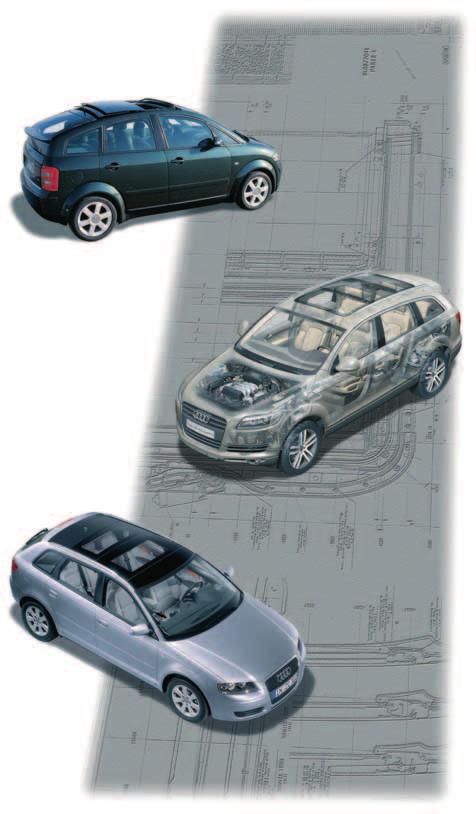
4 Introduction Audi open sky roof systems The so-called open sky roof system is fitted in the A2, A3 Sportback and Q7. The open sky roof system has the advantage over a conventional sliding/tilting sunroof in that it allows more daylight to enter the interior of the vehicle. This creates a feeling of space similar to that in a convertible, but with the advantage of less draught in the interior. The roof system has a variety of functions which enable the occupants to open the sunroof at the front or rear, to open the front roof panel and leave the rear panel closed, or to create a large roof opening by opening both glass roof panels. It is also possible to activate the sun screen when the sunroof is open. The open sky roof system is, therefore, a multifunctional sliding/tilting sunroof. The open sky roof system is integrated into the roof structure, and can be removed and installed separately. The open sky roof, which is bonded or bolted depending on type, helps to increase the rigidity and strength of the body structure as a whole. 378_065 4

5 Audi A2 roof Glass roof panels - explosion drawing Glass roof panel 3 Glass roof panel 2 Glass roof panel 1 bonded Glass roof panel 4 Wind deflector Sliding sunroof motor Cover frame for open sky system Rear guide Front guide 378_003 Guide rails 5


6 Audi A2 roof Glass roof panel 2 closed Glass roof panel 2 is closed. The guides are in the rest position. 378_004 Glass roof panel 3 Glass roof panel 1 Glass roof panel 2 Glass roof panel 2 closed Glass roof panel 3 closed 378_005 When the roof is closed, the left and right guides are in their rest position at the front stops on the guide rails. In this position, the guides and glass roof panel 2 glass are located below roof panel 1 and glass roof panel _006 6


7 Glass roof panel 2 opens - tilts up The motor-driven cable pulls on the left and right are attached to the front guides. When the sunroof switch is held in the "open" position, the cable pulls retract along the guide rails together with the guide due to the direction of rotation of the motor. 378_007 Glass roof panel 3 Glass roof panel 1 Glass roof panel 2 Glass roof panel 2 tilted up Glass roof panel 3 closed 378_010 The lower part of the two-part guide moves back along the lifting arm track and lifts the upper part. This is accomplished by means of sliding blocks located at the front end of the guide rails. The wind deflector remains in the closed position. Sliding blocks 378_008 7
8 Audi A2 roof Glass roof panel 2 begins to open 378_009 Glass roof panel 3 Glass roof panel 1 Glass roof panel 2 After this, the sliding blocks retract from the front insert and commence the opening phase of the front glass roof panel. The front glass roof panel is now tilted up to the full-open position and simultaneously lifted out at the front edge by the front insert and the front sliding blocks to the extent that it is actually located above the side wall frame. Thus, it is now possible to slide open the glass roof panel. Glass roof panel 2 begins to open. The front edge of the sunroof is raised to the extent that a uniform distance to glass roof panel 3 is maintained. Release phase of guide, glass roof panel 3 Guide, glass roof panel 3 Guide, glass roof panel 2 378_012 Locking hook The locking hook on the guide of glass roof panel 3 is lifted out of the locking hook window (guide rail) by the fork of glass roof panel 2. Opening of glass roof panel 2 and tilting up of glass roof panel 3 378_014 The guide of glass roof panel 3 is released and glass roof panel 3 is tilted up by the lifting arm which runs along the guide of glass panel 3. 8

9 Glass roof panel 2 opens - Glass roof panel 3 is locked 378_013 Locking hook Spring element of the locking hook After opening approximately halfway, the guide of the front glass roof panel reaches the guide of the rear glass roof panel, which is still closed at this point. A fork on the front guide engages a spring loaded locking hook on the front part of the rear guide at the rear and lifts the hook out of the locking hook window in the guide rail. Locking hook is lifted out 378_015 9


10 Audi A2 roof Glass roof panel 2 open - glass roof panel 3 opens After the locking hooks have been lifted out, the front guide can now raise the rear glass roof panel in a similar manner to the front glass roof panel by pushing the guide back along the lifting arm track. It can then open both roof panels jointly. Glass roof panel 3 378_011 Glass roof panel 1 Glass roof panel 2 Glass roof panel 2 and glass roof panel 3 open 378_018 Glass roof panel 2 is located above glass roof panel 3 - both glass roof panels are open. The glass roof panel closes in reverse sequence of opening. Locking hook Guide, roof 2 open 378_017 10

11 Electrical system The slide/tilt function of the open sky roof on the Audi A2 is implemented by using sliding sunroof motor V1 and sliding sunroof control unit J245. Both components are located in a common housing. The sliding sunroof control unit J245 receives the control signals from sunroof switch E8. According to the operating logic, these are: open roof, close roof or button not pressed (hold roof position) When opening the roof, the glass roof panel is tilted up if the button is pressed; if the button is pressed again, the open sky roof opens fully or for as long as the button is pressed. The roof closes without intermediate stop in the tilted-up position as long as the button is pressed. The sliding sunroof control unit J245 receives the following information from the convenience system central control unit J393 across two discrete lines: 1. Convenience locking The roof can be closed completely by activating the convenience locking function on the lock cylinder 2. Run-on enable After turning off the ignition with the doors closed, a run-ontime of 10 minutes is activated; the roof can be opened or closed within this period by pressing the button The open sky control unit must be reinitialised after work on the roof or after replacing the drive motor in order to memorise the respective limit positions. The motor can be removed and installed in any position. The control unit cannot be diagnosed with the workshop tester because the system does not have self-diagnostic capability. Note In the case of older Audi A2 open sky systems, there is a version without automatic intermediate stop in the tilted-up position. Sliding sunroof motor V1 with sliding sunroof control unit J _055 11

12 Audi A2 roof Function diagram 378_001 Legend E8 J245 J393 V1 Sunroof switch Sliding sunroof control unit Convenience system central control unit Sliding sunroof motor Positive Ground Input signal 12

13 Audi A3 Sportback sunroof Glass roof panel closed Glass roof panel, non-moving - with roll-up sun screen Roof panel - painted fixed roof panel Sliding/tilting glass roof panel with roll-up sun screen Glass roof panel - fixed 378_031 The sliding blocks attached to the lifting arms and guides track along the guide rails of the sliding sunroof frame and enable the sunroof to glide forwards and backwards. The front sliding blocks attached to the upper lifting arm are located in the guide rail insert at the front when the glass roof panel is closed. In this position, the upper lifting arm is lower at the front end because the guide is routed downward. The lower guide connected to the lifting arm is located at the front at the start of the lifting arm track and simultaneously engages the front lock. The upper rear lifting arm is locked by the rear locking hook. Sunroof lifting arm Insert in guide rail 378_032 Locking hook engaged Sliding blocks 13

14 Audi A3 Sportback sunroof Releasing the glass roof panel locking hook Rear locking hook engaged - sunroof lifting arm closed Sunroof lifting arm Front lock engaged 378_039 Locking hook disengaged 378_040 When the glass roof panel is opened, the guide is retracted. At the same time, bolts attached to the guides lift and retract the front locking mechanism. After approximately 17 mm, the rear locking hook releases the lifting arm. The guide which moves further back raises the lifting arm due to the contour of the lifting arm track and tilts the glass roof panel up. Sunroof lifting arm track Locking hook disengaged Sunroof lifting arm tilts up - wind deflector still closed 378_041 14
15 Glass roof panel tilted up 378_033 The roof panel is tilted up and still keeps the springloaded wind deflector closed. The next stage of the roof opening cycle now commences. 378_034 Locking hook Sunroof lifting arm - glass roof panel tilted up Wind deflector closed 15
16 Audi A3 Sportback sunroof Glass roof panel opens - wind deflector tilts up 378_035 To open the glass roof panel from the "roof tilted up" position, the upper lifting arm is retracted by the outer lifting arm guide connected to the lower guide. The upper lifting arm is retracted from the lower insert in the guide rail and moved into a horizontal position at the front. The guide together with the lifting arm are moved in the opening direction of the sunroof. Wind deflector open 378_036 Outer side lifting arm guide lower insert - guide rail front 16

17 Glass roof panel open 378_037 To completely open the glass roof panel, the guide is now pushed back to the limit position, in which the drive motor is turned off. The glass roof panel closes in reverse sequence of opening. 378_038 Sunroof lifting arm in limit position - roof fully open 17

18 Audi A3 Sportback sunroof Electrical system The tilt-open/slide function of the open sky roof of the Audi A3 Sportback is, like in the Audi A2, realised by using the sliding sunroof motor V1 and sliding sunroof control unit J245. Both components are located in a common housing. The sliding sunroof control unit J245 receives the operating signals from the sunroof button E325. These are: open roof, close roof or button not pressed (hold roof position) When opening the roof, the glass roof panel is tilted up if the button is pressed; pressing the button opens the open sky roof automatically, or manually for as long as the button is pressed. The roof closes without intermediate stop in the tilted-up position as long as the button is pressed. The sliding sunroof control unit J245 receives the following information from the convenience system central control unit J393 over three discrete lines: 1. Convenience locking The roof can be closed completely by activating the convenience closing function at the lock cylinder or the IR remote control 2. Run-on enable After turning off the ignition while the doors are closed, a run-on time of 10 minutes is activated; the roof can be opened or closed within this period by pressing the button 3. Road speed signal At present, the road speed signal is not evaluated by the control unit The drive motor of the open sky system of the Audi A3 Sportback may only be removed and installed in the "roof closed" position, because the system uses internally an absolute encoder for each roof position. This is why initialisation is not possible. The control unit cannot be diagnosed with the workshop tester because the system does not have self-diagnostic capability. Sliding sunroof motor V1 with sliding sunroof control unit J _056 18

19 Function diagram 378_002 Legend E325 J245 J393 V1 Sunroof button Sliding sunroof control unit Convenience system central control unit Sliding sunroof motor Positive Ground Input signal 19

20 Audi Q7 sunroof Glass roof panels - explosion drawing Glass roof panel 3 rear - tilt-opening only Glass roof panel 2 centre - non-opening Glass roof panel 1 front - slide and tilt-opening Sealing elements Roll-up sun screen front and rear Wind deflector Guide - rear tilt mechanism Frame - slide/ tilt mechanism 378_019 Wiring harness and roof positioning motors Guide - front tilt mechanism 20

21 Glass roof panel 1 closed Glass roof panel 2 centre non-opening Glass roof panel 3 rear tilt Glass roof panel 1 front Slide - tilt 378_020 Guide rear tilt mechanism Glass roof panel 3 Guide front tilt mechanism Glass roof panel 1 The front glass roof panel mechanism comprises guides at the bottom and a tilt mechanism at the top. The guides - consisting of interconnected front and rear parts - are half-shell shaped. The lifting arm tracks, along which the tilt mechanisms run, are integrated in the guides. Tilt mechanism 378_021 Rear roof support track pivot - attached to guide rail 378_030 Glass roof panel 1 Sunroof lifting arm track Rear guide Glass roof panel 3 When the roof is closed, the left and right guides in the guide rails are located in their rest position at the front stops. The tilt mechanism is aligned horizontally and the front guide bolts are in a lowered position. Sunroof lifting arms 1 and 2 in rest position Tilt mechanism Guide including lifting arm track in front part glass roof panel 1 Insert in the guide rail Guide including lifting arm track rear part 378_049 Connector, front and rear guides Guide bolt - tilt mechanism 21

22 Audi Q7 sunroof Glass roof panel 1 tilted up 378_022 The lower guides are retracted by electric motor driven linkages. The front guide bolts on the upper mechanism remain fixed in the lowered position. The rear part of the tilt mechanism is raised by the lifting arm track running along the rear guide, and the glass roof panel attached to the tilt mechanism is tilted up. Tilt mechanism 378_023 Sunroof lifting arm track - guide rear section Guide bolt Mechanism tilted up 378_050 Guide bolt located 22

23 Glass roof panel 1 front opens - wind deflector tilts up The glass sunroof is not shown here for illustration reasons. 378_024 Insert for locating the guide bolt To open the glass roof panel from the - roof tilted up - position, the upper mechanism is retracted from the lower insert of the guide rail through the release of the upper guide bolt and moved into a horizontal position. In this position, the guide together with the tilt mechanism are retracted in the opening direction of the sunroof. The spring-loaded wind deflector is released and tilts up. Tilt mechanism 378_025 Guide bolt locating insert To illustrate the lifting arm movements more clearly, only the inner lifting arm tracks of the front and rear guides are shown together with the tilt mechanism. 23


24 Audi Q7 sunroof Glass roof panel 1 fully open - above glass roof panel 2 Glass roof panel 3 Glass roof panel 1 378_028 To fully open glass roof panel 1, the left and right outer guides are moved back past glass roof panel 2. The glass roof panel closes in reverse sequence of opening. 378_ _051 24


25 Glass roof panel 3 rear tilted up Glass roof panel 3 Glass roof panel 1 378_028 Glass roof panel 3 is designed as a tilt sunroof. Roof panel 3 and roof panel 1 have different lower guides and upper tilt mechanisms. The front guide is bolted to the guide rail. The upper tilt mechanism is inserted in the pivot at the front and in the lifting arm track at the rear. The tilting distance is defined fixed pivot and the reduced travel in the lifting arm track. Opening and tilting of glass roof panel 3 are initiated by the retraction of the guide. When the guide moves, the tilt mechanism opens (tilts up) the glass roof panel as it travels along lifting arm track. The roof panel closes in reverse sequence of opening. 378_029 Tilt mechanism, top Front guide 378_052 Rear guide Lifting arm track Pivot 25

26 Audi Q7 sunroof Electrical system The system used on the Audi Q7 is very different to the open sky systems of the Audi A2 and the Audi A3 Sportback. Three drive motors are required to implement the various functions of the roof. Each drive motor accommodated in a housing together with the control unit and configured as a LIN slave. The sliding sunroof control unit J245, in conjunction with the sliding sunroof motor V1, which drives glass roof panel 1, also serves a central control function. All information from the controls of the open sky system is read in by the sliding sunroof control unit J245 and transferred to the LIN data bus whereby the convenience system central control unit 2 J773 acts as the LIN master. E139 E8 E191 sliding sunroof adjustment regulator with potentiometer (settings 0-7) for glass roof panel 1 and the integrated button (setting 8) for full opening with tilt sunroof button 1 E582 and sunroof roller sun blind button 1 E584 with tilt sunroof button 2 E583 and sunroof roller sun blind button 2 E585 Modules E139 and E8 are integrated in the front operating unit and module E191 is integrated in the rear operating unit. Warning lamp K96, which is activated when the sunroof is tilted up, is also integrated in tilt sunroof button 1. Note For further information on the operation, function and initialisation of the open sky system of the Audi Q7, please refer to SSP364 "Audi Q7 - Electrical System, the operating manual and the workshop literature. E191 Rear sunroof switch with buttons E583 and E585 E8 Sunroof switch with buttons E582 and E584 E139 Sliding sunroof adjustment regulator 378_053 26

27 Position of the control units/drive motors and wiring Sunroof roller blind motor V260 with sunroof roller blind control unit J _054 Rear sliding sunroof motor V146 with rear sliding sunroof control unit J392 Sliding sunroof motor V1 with sliding sunroof control unit J245 The convenience system central control unit 2 J773 is connected via the LIN data bus to the control units of the open sky system of the Audi Q7. For this reason, this system, unlike the open sky systems of the Audi A2 and Audi A3 Sportback, is diagnosable. All drive motors have an anti-pinch protection feature whereby the force required to initiate the anti-pinch protection feature and reverse the drive motor is dependent on the speed at which the vehicle is travelling. When driving at high speeds, the effects of wind load are largely compensated. In addition to finding faults with the guided fault finding function, fault memory entries and data blocks can be read, final control tests performed and codings can be configured. Note After working on the electrical system of the open sky system of the Audi Q7 or after removing and assembling a glass roof panel, the associated drive motor and/or the control unit must be adapted. 27

28 Audi Q7 sunroof Function diagram Convenience CAN bus Legend E8 Sunroof switch E139 Sliding sunroof adjustment regulator E191 Rear sunroof switch E582 Tilt sunroof button 1 E583 Tilt sunroof button 2 E584 Sunroof roller sun blind button 1 E585 Sunroof roller sun blind button 2 J245 Sliding sunroof control unit J392 Rear sliding sunroof control unit J394 Sunroof roller blind control unit J773 Convenience system central control unit 2 K96 Warning lamp "rear tilt sunroof opened" V1 Sliding sunroof motor 28
 Convenience CAN data bus")
29 378_048 Positive V146 V260 Rear sliding sunroof motor Sunroof roller blind motor Ground Input signal D Connection for motor diagnostics by manufacturer Output signal Communication interface from control unit J392 earth in sunroof wiring harness Earth in sliding sunroof wiring harness LIN data bus Convenience CAN data bus (CAN-high) Convenience CAN data bus (CAN-low) 29


30 Service Special tools Here you can see the special tools for open sky sunroofs. V.A.G _ _064 V.A.G 1561/2 V.A.G 1561/11 378_ _061 V.A.G 1561/22 30


31 378_062 VAS 6010 Can be obtained on loan through your sales centre or your importer 378_063 V.A.G 1561 A 378_059 VAS
32 Vorsprung durch Technik All rights reserved. Technical specifications subject to change without notice. Copyright AUDI AG I/VK-35 Fax / AUDI AG D Ingolstadt Technical status: 03/06 Printed in Germany A06.5S
In total, there are four different versions of the data bus diagnostic interface: Data bus diagnostic interface J533
 New features The data bus diagnostic interface now also includes a battery power management function. For this purpose, a LIN line is connected to a socalled "battery data module" located directly adjacent
Service Training. Audi A4 Cabriolet convertible top control. Self-Study Programme 314
 Service Training Audi A4 Cabriolet convertible top control Self-Study Programme 314 Introduction The perfectly shaped Audi Cabriolet continues to enjoy undiminished popularity. Innovative technology, sportiness,
Service Training. Audi A5 - Networking. Self-Study Programme 395
 Service Training Audi A5 - Networking Self-Study Programme 395 Innovations in the electrical system and electronics on the Audi A5 The number of s in motor vehicles continues to increase, and the Audi
Phaeton Convenience and Safety Electronics
 Service. Self-Study Programme 273 Phaeton Convenience and Safety Electronics Design and Function Open sesame - thanks to a new system for entry and start authorisation, the Phaeton can be accessed without
Convenience system central control unit
 Convenience system central control unit The convenience system central control unit monitors and controls the following functions: Convenience system central control unit central locking unlocking the
The electro-mechanical power steering with dual pinion
 Service Training Self-study programme 317 The electro-mechanical power steering with dual pinion Design and function The electro-mechanical power steering has many advantages over the hydraulic steering
Phaeton Convenience and Safety Electronics
 Service. Self-Study Programme 273 Phaeton Convenience and Safety Electronics Design and Function Open sesame - thanks to a new system for entry and start authorisation, the Phaeton can be accessed without
The electromechanical parking brake
 Service Training Self-study programme 346 The electromechanical parking brake Design and function To make absolutely sure that the vehicle could not roll away when parked up, the driver had to pull up
HIGH-VOLTAGE BATTERIES DIAGNOSTICS & MAINTENANCE TRAINER
 Lucas Nülle is proudly and exclusively represented in Australia and New Zealand by Training Systems Australia First in Vocational Training Equipment A Division of Pullman Learning Group 300 Centre Road,
Service 5. Workshop Manual FABIA Body Work Edition Service Department. Technical Information. Printed in Czech Republic S
 Service 5 Workshop Manual FABIA 2000 Body Work Edition 08.99 Service Department. Technical Information Printed in Czech Republic S00.5319.00.20 5 Service The Workshop Manual is intended only for use within
Table of Contents. E70 Panorama Glass Sunroof. Introduction...3 Operating Concept...3
 Table of Contents troduction..................................................3 Operating Concept.............................................3 System Overview.............................................4
Audi > Q7 > Electrical Equipment 27 - Removal and Installation. Battery. Special tools, testers and auxiliary items required
 Page 1 of 5 Audi > Q7 > 2007-2008 Electrical Equipment 27 - Removal and Installation. Battery Special tools, testers and auxiliary items required Pry lever 80-200 Vehicle Diagnostic, Testing and Information
The Transporter 2004 Electrical system
 Service. Self-study programme 311 The Transporter 2004 Electrical system Design and function The Transporter 2004 has an extensive network of electronic control units. Functions which were controlled in
1. Normalization: upper end position. 2. Characteristic curve learning: the characteristic curve of opening and closing the electric current
 Technical Guidance BMW: Register Battery Replacement Register battery replacement BMW after model E65, it is essential to register the battery replacement after replacing or disconnecting the battery.
Introduction Central Locking and Soft Close Doors System Overview Components Principle of Operation Power Windows...
 Table of Contents CENTRAL BODY ELECTRONICS Subject Page Introduction............................................... 3 Central Locking and Soft Close Doors........................ 4 System Overview........................................
Purpose. Revised Service
 Technical Service Bulletin Transaction No.: 2022733/2 60 Noises from sunroof Release date: Apr 29, 2010 Condition REVISION HISTORY Revision Date Purpose 2 - Revised header data (Added models) Revised Service
Service Training. Audi Q7 - Electrical System. Self-Study Programme 364
 Service Training Audi Q7 - Electrical System Self-Study Programme 364 The Audi Q7 stands for 100% premium-quality electronics! There has been an enormous increase of the number of electronic s over the
Wipers and Washers. Wiper and Washer System Component Location
 Page 1 of 17 Published : Mar 30, 2005 Wipers and Washers Wiper and Washer System Component Location Item Part Number Description 1 Front washer jets 2 Wiper control switch 3 Rain/Light sensor 4 Rear wiper
Convenience electronics
 Convenience electronics Operating conditions Various conditions have to be met to enable roof movement to be carried out. This applies to opening and closing the convertible roof. One vital element of
Table of Contents. E70 Seats. Introduction...4 Seat Equipment Options...4 Second Row Seating...6 Third Row Seating...7
 Table of Contents Subject Page Introduction..................................................4 Seat Equipment Options........................................4 Second Row Seating.........................................6
Passenger s Side Airbag, On Board Diagnostic (OBD) Service
 Service") Subject: Model(s): Passenger s Side Airbag, On Board Diagnostic (OBD) All 2000 Group: Number: Date: 01 00 03 Apr. 24, 2000 Supersedes T.B. group 01 number 99 21 dated Dec. 8, 1999 Black revision bars indicate
Subject: Model(s): Passenger s Side Airbag, On Board Diagnostic (OBD) All 2000 Group: Number: Date: 01 00 03 Apr. 24, 2000 Supersedes T.B. group 01 number 99 21 dated Dec. 8, 1999 Black revision bars indicate
Table of Contents. E93 Retractable Hardtop. Introduction...5. System Overview...7 Conditions for Operation...7
 Table of Contents Subject Page Introduction..................................................5 System Overview.............................................7 Conditions for Operation........................................7
Removing and installing trim panel
 Removing and installing trim panel vw-wi://rl/a.en-gb.a03.5106.29.wi::31914802.xml?xsl=3 1. oldal, összesen: 1 oldal Removing and installing trim panel Removing Carefully prise out trim panel -1- in direction
Volkswagen B3 Passat Diagnosis, Fault Memory - Passat Diagnosis, Fault Memory (Page GR-D4)
") Diagnosis, Fault Memory (Page GR-D4) Anti-lock brake system (ABS) electrical testing self-diagnosis troubleshooting using electrical steps VAG 1551 Diagnostic Tester connecting erasing Fault memory reading
Diagnosis, Fault Memory (Page GR-D4) Anti-lock brake system (ABS) electrical testing self-diagnosis troubleshooting using electrical steps VAG 1551 Diagnostic Tester connecting erasing Fault memory reading
Installation instructions
 Service Installation instructions Audi A4/A5 (B8 series) 2008 Engine sound system For scope of delivery 8T0.071.901* Audi Genuine Accessories Service Department. Technical Information Service Contents
Airbags, servicing. Airbag system, safety precautions WARNING!
 Page 1 of 75 69-40 Airbags, servicing Airbag system, safety precautions Checking, removing, installing and servicing may ONLY be performed by qualified personnel. Never perform tests using a test light
8.1 Main Light Switch
 8.1 Main Light Switch All models have the same main light switch implementation mounted in the top left dashboard pod position. This 3 position switch has 2 poles with variously configured throws on the
00 02 Apr. 24, Service
 Subject: Model(s): Driver s Side Airbag, On Board Diagnostic (OBD) All 2000 Group: Number: Date: 01 00 02 Apr. 24, 2000 Supersedes T.B. group 01 number 99 20 dated Dec. 8, 1999 Black revision bars indicate
Convenience CAN databus
 Convenience CAN databus The convenience CAN databus operates with a transmission rate of 100 kbit/s. Onboard power supply control unit J519 with databus diagnostic interface J533 (gateway) CLIMAtronic
English/Chinese/Japanese /Korean iscan-ii FORD V3.01 / V2.03 / V1.05 English/Chinese
 Back to Main Trade Show AAAE 2011 Australian Auto Aftermarket Expo May 12 - May 14, 2011 Melbourne Exhibition Centre, Australia Booth Number: F14F Automechanika Middle East 2011 June 7 - June 9, 2011 Dubai
6-speed manual gearbox 0A5
 Service Training Self-study programme 320 6-speed manual gearbox 0A5 Design and function S320_002 In addition to meeting increasing technical demands, modern cars also have to represent effective space
SERVICE MANUAL. Hollandia 300 Large
 SERVICE MANUAL Hollandia 300 Large 1 BEFORE BEGINNING THE SERVICE PROCEDURE 1. Determine which model of the Hollandia 300 Large is installed in the vehicle. 2. Diagnose the problem by using the Trouble
The Eos 2006 Electrical system
 Service Training Self-study Programme 379 The Eos 2006 Electrical system Design and function The Volkswagen Eos takes a pioneering approach to convertible roof technology. Besides the actual convertible
Service Training. Audi A6 05 Electrics. Self-Study Programme 326
 Service Training Audi A6 05 Electrics Self-Study Programme 326 The Audi A6 the most progressive vehicle takes the lead The new Audi A6 the most progressive vehicle takes the lead. The new Audi A6 consistently
Electronic Engine Power Control (EPC) (E-Gas), checking
 (E-Gas), checking") Page 1 of 51 24-113 Electronic Engine Power Control (EPC) (E-Gas), checking E-Gas system, function For E-Gas, the throttle valve is not operated by a cable from the accelerator pedal. There is no mechanical
Page 1 of 51 24-113 Electronic Engine Power Control (EPC) (E-Gas), checking E-Gas system, function For E-Gas, the throttle valve is not operated by a cable from the accelerator pedal. There is no mechanical
Key Explanation Key Explanation 1 Rain-light sensor (RLS) 2 Light switch
 2 Light switch") E60, E61, E63, E64 from 03/2005 - Light module with adaptive headlights From 03/2005, the adaptive headlights are integrated into the light module. Installation location The light module is installed in
E60, E61, E63, E64 from 03/2005 - Light module with adaptive headlights From 03/2005, the adaptive headlights are integrated into the light module. Installation location The light module is installed in
Webasto Products N.A. Inc.
 Webasto Products N.A. Inc. Hollandia 300 Large Hollandia 300 Large Sliding Shade INSTALLATION MANUAL (SECTION - 1) CONTENTS OF THE WEBASTO 300 LARGE INSTALLATION & SERVICE MANUAL SECTION SUBJECT PAGE NUMBER
Rear Drive Axle and Differential
 Page 1 of 13 Rear Drive Axle and Differential GENERAL Item Part Number Description A - Electronic rear differential B - Open rear differential 1 - Rear driveshaft 2 - Electronic rear differential 3 - RH
Spoiler Service Guide
 Spoiler Service Guide Offered by Signature Automotive Products For 2011 Spoiler Service Manual Glass Panel Removal: Cycle the glass panel into the open position. Allowing access to the four (4) T-25 torx
4.10 Infrared Remote Central Locking (RCL) Contents
 Contents") 4.10 Infrared Remote Central Locing (RCL) Contents 4.10 Models 129, 140, 170 as of M.Y. 1998 Page Diagnosis Function Test................................... 11/1 Diagnostic Trouble Code (DTC) Memory................
4.10 Infrared Remote Central Locing (RCL) Contents 4.10 Models 129, 140, 170 as of M.Y. 1998 Page Diagnosis Function Test................................... 11/1 Diagnostic Trouble Code (DTC) Memory................
The steering column is only available as a complete unit, without steering lock housing, as a replacement part.
 Page 1 of 17 Volkswagen > New Beetle > 1998-2005 Suspension, wheels, steering 48 - Steering column Steering column, removing and installing Special tools, testers and auxiliary items required Torque wrench
Self-Adjusting Clutch (SAC) Technology Special tools / User instructions
 Technology Special tools / User instructions") Self-Adjusting Clutch (SAC) Technology Special tools / User instructions The content of this brochure shall not be legally binding and is for information purposes only. To the extent legally permissible,
Self-Adjusting Clutch (SAC) Technology Special tools / User instructions The content of this brochure shall not be legally binding and is for information purposes only. To the extent legally permissible,
5 Mechanisms and accessories
 5 Mechanisms and accessories 51A SIDE OPENING ELEMENT MECHANISMS 52A NON-SIDE OPENING ELEMENT MECHANISMS 54A WINDOWS 55A EXTERIOR PROTECTION 56A EXTERIOR EQUIPMENT 57A INTERIOR EQUIPMENT 59A SAFETY ACCESSORIES
Front seats. j a t CAUTION! Before beginning repairs on the electrical system: Obtain the anti-theft radio security code. Switch the ignition off.
 j a t Front seats 72-1 CAUTION! Before beginning repairs on the electrical system: Obtain the anti-theft radio security code. Switch the ignition off. Search Advanced Search Disconnect the battery Ground
Battery, Mounting and Cables - Battery and Cables Description and Operation
 Battery, Mounting and Cables - Battery and Cables Description and Operation COMPONENT LOCATION - SINGLE BATTERY VEHICLES Item 1 2 3 4 5 6 7 8 9 10 Description Jump start terminal negative (-) Jump start
E61, E63, E64 BMW AG - TIS
 VS-42 je Baugruppe/Group: 61 meeknet.co.uk/e64 Power supply E60, E61, E63, E64 61 07 03 (029) weltweit Datum/Date: 06/2003 Update 02/2006 Introduction The power supply on the BMW 5- and 6-Series is similar
Audi A6 Comfort Control Module Wiring Diagram
 We have made it easy for you to find a PDF Ebooks without any digging. And by having access to our ebooks online or by storing it on your computer, you have convenient answers with audi a6 comfort control
MICROGUARD 500 EXTENSION REEL TRAINING MANUAL. Greer Company. Greer Company Crane Systems 1 OF18
 MICROGUARD 500 EXTENSION REEL TRAINING MANUAL 1 OF18 TABLE OF CONTENTS MICROGUARD 500 SERIES EXTENSION REEL TRAINING MANUAL EXTENSION REEL OVERVIEW...3 REEL-OFF CABLE LAYERING...3 CHECKING THE REEL-OFF
DLKEK3HN INSTALLATION INSTRUCTIONS
 DLKEK3HN INDEX: INSTALLATION INSTRUCTIONS WIRING INSTRUCTIONS... PG 2-5 LED STATUS INDICATOR... PG 6 VALET/OVERRIDE BUTTON... PG 6 SHOCK SENSOR... PG 7 PROGRAMMABLE JUMPER-PINS... PG 7 PROGRAMMING REMOTE
E61, E63, E64, E70, E81, E87, E90, E91, E92, E93 BMW AG - TIS
 VS-42 je Baugruppe/Group: 66 66 04 04 (093) Comfort Access E60, E61, E63, E64, E70, E81, E87, E90, E91, E92, E93 weltweit Datum/Date: 05/2004 Update: 07/2007 meeknet.co.uk/e64 Introduction The BMW 1-Series,
MASS AIR FLOW (MAF) SENSOR, CHECKING - BOSCH
 SENSOR, CHECKING - BOSCH") 2004 Audi A6 Sedan (4B2) V6-2.7L Turbo (BEL) Vehicle > Powertrain Management > Computers and Control Systems > Testing and Inspection > Component Tests and General Diagnostics > Component Tests > Mass
2004 Audi A6 Sedan (4B2) V6-2.7L Turbo (BEL) Vehicle > Powertrain Management > Computers and Control Systems > Testing and Inspection > Component Tests and General Diagnostics > Component Tests > Mass
5 Mechanisms and accessories
 5 Mechanisms and accessories 51A SIDE OPENING ELEMENT MECHANISMS 52A NON-SIDE OPENING ELEMENT MECHANISMS 54A WINDOWS 55A EXTERIOR PROTECTION 56A EXTERIOR ACCESSORIES 57A INTERIOR ACCESSORIES 59A SAFETY
Service. Adaptive cruise control in the Audi A8 Design and operation. Self Study Programme 289. For internal use only
 289 Service. Adaptive cruise control in the Audi A8 Design and operation Self Study Programme 289 For internal use only Adaptive cruise control is a new system designed to assist drivers and offers a much
GENERAL VEHICLE INFORMATION FRONT LOWER STRUCTURE CENTRE LOWER STRUCTURE UPPER FRONT STRUCTURE NON-SIDE OPENING ELEMENTS
 4 Panelwork 40A GENERAL VEHICLE INFORMATION 41A FRONT LOWER STRUCTURE 41B CENTRE LOWER STRUCTURE 41C SIDE LOWER STRUCTURE 41D REAR LOWER STRUCTURE 42A UPPER FRONT STRUCTURE 43A SIDE UPPER STRUCTURE 44A
Onboard power supply management
 Onboard power supply management The onboard power supply J519 Functions of onboard power supply control unit Until now s and relays functioned at different locations in the vehicle. In the onboard power
Edition Manual Chapter Page Workshop Manual, Stiga Park 4 Hydraulic system 37
 2008-05-19 Workshop Manual, Stiga Park 4 Hydraulic system 37 13.Remove the diff-lock lever spring & hook clip. 14.Remove the diff-lock lever. 15.Open the transmission case by prying up on the lower case
Reference Manual C1S Class 1 Systems
 Reference Manual C1S 2010 Class 1 Systems Mission Statement To become the preferred supplier of electrical lighting and safety solutions for mobile plant and equipment in the mining and services industry.
SIDE ROLL SENSOR TROUBLESHOOTING GUIDE
 SIDE ROLL SENSOR TROUBLESHOOTING GUIDE WARNING Service the roll sensor(s) only if you are an authorized technician. The roll sensor triggers airbags and seat restraints. Accidental deployment could cause
Service and Repair. NOTE: Before proceeding, review all Steering Column and Airbag Warnings and Cautions.
 ALLDATA Online - 2003 Chrysler Truck Town & Country V6-3.8L VIN L - Service and... Page 1 of 10 Home Account Contact ALLDATA Log Out Help BILL SEIDLES MITSUBISHI Select Vehicle New TSBs Technician's Reference
Engine, removing and installing
 Стр 1 из 16 10-1 Engine, removing and installing Special tools, testers and auxiliary items required Torque wrench VAG 1331 Torque wrench VAG 1332 Engine/transmission jack VAG 1383 A Spring type clip pliers
Electromechanical Steering with Parallel-axis Drive
 Service Training Self-study Programme 399 Electromechanical Steering with Parallel-axis Drive Design and Function The electromechanical power steering has many advantages compared with a hydraulic steering
Installation instructions for the TriVision Car Docking Station
 Contents 1. Symbols used in this installation guide......................................... 30 2. Prior to installation......................................................... 31 3. Safety instructions.........................................................
Special tools required:
 11 36 040 Removing and installing, sealing/replacing right VANOS adjustment unit (S62) Special tools required: 11 7 130 12 6 050 12 6 410 12 6 411 Read fault memory and make a documentary record. When
Holden VZ 3.6L ECU & Powertrain Interface Module Linking Instructions
 Holden VZ 3.6L 2004-2006 ECU & Powertrain Interface Module Linking Instructions Contents Page In Brief PIM Replacement, ECM Replacement 2 VZ 3.6L System Overview 3 PIM Functions 4 PIM Location 4 ECM Functions
SECTION Transaxle, Automatic-External Controls
 07-05- 1 Transaxle, Automatic-External Controls 07-05- 1 SECTION 07-05 Transaxle, Automatic-External Controls SUBJECT PAGE SUBJECT PAGE ADJUSTMENTS REMOVAL AND INSTALLATION Shift Control Cale... 0705-12
On Board Diagnostic (OBD)
") Page 1 of 19 01-1 On Board Diagnostic (OBD) On Board Diagnostic (OBD), technical data Equipment Data is transmitted between the control module and the VAS5051 tester or VAG1551 Scan Tool (ST) via operating
Page 1 of 19 01-1 On Board Diagnostic (OBD) On Board Diagnostic (OBD), technical data Equipment Data is transmitted between the control module and the VAS5051 tester or VAG1551 Scan Tool (ST) via operating
Onboard Power Supply. Relay Carriers and Fuse Boxes. Locations. Relay carrier. Relay carrier on onboard power supply control unit
 Onboard Power Supply Relay Carriers and Fuse Boxes Locations The relay carrier and the onboard power supply control unit are under the left-hand side of the dash panel. Relay carrier The relays connected
REMOVAL AND INSTALLATION > ROOF OPENING PANEL - EXPLODED VIEW
 Page 1 of 11 2007 Lincoln MKX 3.5L Eng VIN C Service Manual: SUNROOF Print Date: REMOVAL AND INSTALLATION > ROOF OPENING PANEL - EXPLODED VIEW Fig 1: Exploded View Of Exterior Trim, Seals, Fixed Glass
Der PARAVAN KALI V2 Cassette lift Owner`s Manual. User manual/ PARAVAN KALI V3.3 cassette lift (Software-Update 2.0)
") Der PARAVAN KALI V2 Cassette lift Owner`s Manual User manual/ PARAVAN KALI V3.3 cassette lift (Software-Update 2.0) User manual for the PARAVAN KALI V2 cassette lift 1st Introduction The Paravan cassette
Der PARAVAN KALI V2 Cassette lift Owner`s Manual User manual/ PARAVAN KALI V3.3 cassette lift (Software-Update 2.0) User manual for the PARAVAN KALI V2 cassette lift 1st Introduction The Paravan cassette
The parking brake is an electrically actuated system that operates drum brakes integrated into the rear brake discs. The
 Page 1 of 15 Published: Oct 22, 2004 Parking Brake COMPONENT LOCATIONS Item Part Number Description 1 Clutch pedal position sensor (manual transmission models only) 2 Parking brake indicators (all except
Headlamps. Стр. 1 из 34. Headlamps from two different manufacturers may be installed: Hella. Valeo
 Volkswagen Passat B6 2005 - Headlamps Стр 1 из 34 94-1 Headlamps General information Headlamps from two different manufacturers may be installed: Hella Valeo With the exception of the various bulb mountings,
ABB i-bus KNX DG/S x DALI-Gateway Basic
 ABB i-bus KNX DG/S x.64.1.1 DALI-Gateway Basic The lamps are variably controlled via KNX per DALI output via Broadcast (all lamps jointly) 16 lighting groups 64 individual lamps 16 scenes 64 self-contained
CURRICULUM BOSCH-REXROTH (CENTRE OF EXCELLENCE) GANPAT UNIVERSITY
 GANPAT UNIVERSITY") ANNEXURE - A CURRICULUM BOSCH-REXROTH (CENTRE OF EXCELLENCE) Host Institute: GANPAT UNIVERSITY Contents of Basic Industrial Pneumatics -----------------------------------------------------------------------------------------------------------------
ANNEXURE - A CURRICULUM BOSCH-REXROTH (CENTRE OF EXCELLENCE) Host Institute: GANPAT UNIVERSITY Contents of Basic Industrial Pneumatics -----------------------------------------------------------------------------------------------------------------
Ultrasonic interior monitoring On Board Diagnostic (OBD)
") Page 1 of 44 01-108 Ultrasonic interior monitoring On Board Diagnostic (OBD) General Information The ultrasonic interior monitoring system is only offered in conjunction with the anti-theft system. The
Page 1 of 44 01-108 Ultrasonic interior monitoring On Board Diagnostic (OBD) General Information The ultrasonic interior monitoring system is only offered in conjunction with the anti-theft system. The
Removing and installing dash panel insert
 Removing and installing dash panel insert Caution To disconnect and connect the battery, the procedure described in the workshop manual should be strictly adhered to Chapter. Note Pull off multi-pin connector
57-1. Front door. Tools. Special tools and equipment. T Socket 3320/2 Bit insert for Socket T Assembly tool
 57-1 Front door Tools Special tools and equipment T 10011 Socket 3320/2 Bit insert for 3320 3410 Socket T 10034 Assembly tool 57-2 Front door, assembly overview Note: The instrument panel must be removed
E61, E63, E64, E70, E81, E87, E90, E91, E92, E93 BMW AG - TIS
 VS-42 es Baugruppe/Group: 32 meeknet.co.uk/e64 32 01 03 (001) Active Steering E60, E61, E63, E64, E70, E81, E87, E90, E91, E92, E93 weltweit Datum/Date: 04/2003 Update: 02/2007 Introduction Active Steering
RX 60 Technical Data.
 @ RX 60 Technical Data. Electric forklift trucks. RX 60-16 RX 60-18 RX 60-20 2 RX 60 TECHNICAL DATA. This specification sheet to VDI Guideline 2198 only gives the technical figures for the standard truck.
2003 Cadillac DeVille DTS
 TRIM PANEL REPLACEMENT - SIDE FRONT DOOR Tools Required J 36796 Clip Zip Clip Removal Tool, or J 38778 Door Trim Pad Clip Remover Removal Procedure 1. Position the window fully downward. 2. Ensure the
Service Manual Gulf Stream Electronic Full Wall Slide Systems
 Service Manual Gulf Stream Electronic Full Wall Slide Systems CONTENTS Page Before you operate the slide system 2 Operating Instructions 3 Preventive maintenance 3 Manually overriding your slide system
4. REMOVAL AND INSTALLATION OF SUNROOF ASSEMBLY
 7340 7 4. REMOVAL AND INSTALLATION OF SUNROOF ASSEMBLY Exploded View Sunshade assembly Ventilation roof Drain channel Tube cable guide Wind deflector Seal - drive tube Drive tube Frame assembly Sunroof
FTE automotive Innovation drives. Transmission actuation. hydraulic and electromechanical components for automatic transmissions
 FTE automotive Innovation drives Transmission actuation hydraulic and electromechanical components for automatic transmissions 1 Innovative elements for the current development trend Transmission actuators
Installation instructions
 Service Installation instructions Audi A3 (8V3) 2012 Roof bars 8V3.071.126 for vehicles with bright moulding package (PR no. 4ZB) and roof bars 8V3.071.126.L for vehicles with black moulding package (PR
Installation instructions, accessories - Rear Seat Entertainment
 XC90 Section Group Weight(Kg/Pounds) Year Month 3 39 2004 10 XC90 2003, XC90 2004, XC90 2005, XC90 2006, XC90 2007, XC90 2008 Replaces issue: 2003 12 J3904620 Page 1 of 18 Required tools A0000162 A0000163
In area - A -, a proper seal must be made against the top of the window glass.
 Door window, adjusting Page 1 of 3 Audi > B3 > 1994-1998 Body Exterior, Interior 61 - Convertible top, checking and adjusting Door window, adjusting Sections C-C and D-D. Adjust door window so that window
WORKSHOP EQUIPMENT. Tyre changers Recommended by Volkswagen AG
 WORKSHOP EQUIPMENT Tyre changers VAS 6313-C and VAS 6314-C wdk-certified Tyre changer VAS 6313-C Certified by wdk for handling of UHP and run-flat tyres. With pneumatic mounting tool VAS 6312-1 and kit
Assembly instructions Original parking distance control system, Volkswagen
 Assembly instructions Original parking distance control system, Volkswagen Set contents: 1 x controller 1 x buzzer 4 x sensor Set contents: 4 x covering rings 4 x protective rings Special tools, test and
2007 Chevrolet Corvette STEERING Steering Wheel and Column - Corvette. Steering Wheel and Column - Corvette
 2007 STEERING Steering Wheel and Column - Corvette SPECIFICATIONS FASTENER TIGHTENING SPECIFICATIONS Fastener Tightening Specifications Specification Application Metric English Actuator Retaining Screws
Mobile Elevating Working Platform. ISOLI PNT 210 J on NISSAN F24.35 wb 3400 mm
 ISOLI PNT 210 J on NISSAN F24.35 wb 3400 mm Date: 19.12.2014 Pag. 2 / 9 MAIN NEW FEATURE AND IMPROVEMENT PERFORMANCE Increased payload in the basket Max payload : 250 kg (with load cell by MOBA) Increased
Removing and installing front windscreen
 51 31 000 Removing and installing front windscreen To bond windshield: Adhesives for cold and hot working are permitted. Remove interior rearview mirror, refer to 51 16 060. If necessary, remove rain sensor,
TOYOTA COROLLA EC REARVIEW MIRROR Preparation
 Preparation Part Number: PT374-02090 Kit Contents Item # Quantity Reqd. Description 1 1 AD Mirror Assembly w/ PRNDL 2 1 Hardware bag Hardware Bag Contents Item # Quantity Reqd. Description 1 2 T-tap Connectors,
SUPPLEMENTAL RESTRAINT SYSTEM AIRBAG SYSTEM SYSTEM DIAGRAM. Front Airbag Sensor LH Steering Pad (Driver Side Squib)
") 16 SUPPLEMENTAL RESTRAINT SYSTEM AIRBAG SYSTEM SYSTEM DIAGRAM Front Airbag Sensor LH Steering Pad (Driver Side Squib) Front Airbag Sensor RH Front Passenger Airbag Assembly (Front Passenger Side Squib)
16 SUPPLEMENTAL RESTRAINT SYSTEM AIRBAG SYSTEM SYSTEM DIAGRAM Front Airbag Sensor LH Steering Pad (Driver Side Squib) Front Airbag Sensor RH Front Passenger Airbag Assembly (Front Passenger Side Squib)
HIGH TECH SECURES YOUR FUTURE SBA 1200 GB SUN BRAKE ANALYSER. Operating Manual
 HIGH TECH SECURES YOUR FUTURE SUN BRAKE ANALYSER Operating Manual 2 Operating Manual SUN BRAKE ANALYSER Copyright December 2009 Snap-on Equipment GmbH All rights reserved Part number: 2000618380 Rev: 3
4. REMOVAL AND INSTALLATION OF SUNROOF ASSEMBLY AND COMPONENTS
 8 7340 4. REMOVAL AND INSTALLATION OF SUNROOF ASSEMBLY AND COMPONENTS Exploded View Seal - glass panel Glass Wind deflector Glass panel Sunshade assembly Ventilation roof Drain channel support bar pin
5-speed Automatic Gearbox 09A/09B
 Service. Self-Study Programme 232 5-speed Automatic Gearbox 09A/09B Design and Function The new 5-speed automatic gearbox The new automatic gearbox is intended for installation in the Volkswagen and Audi
450 OE/HS Installation Guide
 450 OE/HS Installation Guide Offered by Signature Automotive Products For 2011 The Signature Automotive Products Spoiler is the most advanced technological spoiler sunroof and is available in two models:
1 of 2 5/17/17, 1:22 PM
 1 of 2 5/17/17, 1:22 PM Trim Molding, Removing and Installing Special tools, testers and auxiliary items required Wedge Set (T10383) Removal Wedge (T40233) Removing - Starting at the front, pry the trim
SECTION G2: CABLE PROCESSOR MODULE MAINTENANCE
 SECTION G2: CABLE PROCESSOR MODULE MAINTENANCE Cable Processor Module overview WARNING! When tipping the Cable Processor Module back, (after removing the toggle arm pin), use extreme caution not to drop
Oxygen sensor control,
 Page 1 of 46 24-71 Oxygen sensor control, checking Oxygen sensor and oxygen sensor control before catalytic converter, checking Special Tools and Equipment VAG1526A VAG1594A VAG1598/31 VAS5051 with VAG5051/1
Flashing Arrow Panel - 615/815 T/Y
 Flashing Arrow Panel - 615/815 T/Y All LED 15-Lamp Portable Flashing Arrow Panel Product Specifications American Signal Company FAP X 15 Page 1 of 8 6/11/17 2755 Bankers Industrial Drive Atlanta, GA 30360