Instruction Manual for S-Stage+D KIT (106cc / SCUT / Decompression)
|
|
|
- Silvester Blaze McDonald
- 5 years ago
- Views:
Transcription
1 Thank you for purchasing one of our TAKEGAWA-made products. Please strictly follow the following instructions in installing and using the kit. Before installing the kit, please be sure to check the kit contents. Should you have any questions about the kit, please contact your local motorcycle dealer. Please note that, in some cases, the illustrations and photos may vary from the actual hardware. Instruction Manual for S-Stage+D KIT (106cc / SCUT / Decompression) Item No. Monkey & Gorilla CD50 CL50 Features (Cylinder Kit) Z50J AB CD CD (Patent applied for) Dax CRF50F XR50R AB AE AE The incorporation of a cam shaft with a decompressor mechanism reduces the load on the transmission and kick shaft even on a 106cc engine, made possible, for example, by S-Stage (SCUT) Bore Up Kit, leading to start of engine only with lighter kicking power than before. About fuel to use This S-Stage Kit is so designed to achieve a higher compression ratio than stock engines.therefore, high-octane gasoline should always be used. In case regular gasoline is used, abnormal combustion will take place, and you cannot get the high performance of the Kit. Moreover, it is highly likely that the piston will be damaged, leading to a serious failure of a motorcycle. Before installing this kit, make sure that no regular gasoline remains in the fuel tank. In case regular gasoline is remaining in the fuel tank, do replace it with high-octane gasoline. About the spark plug Be sure to replace a spark plug with a CR8HSA (NGK) or U24FSR-U(DENSO). In the case of a non-resistive plug, please replace with C8HSA (NGK) or U24FS-U (DENSO). Subsequently, choose and use a right spark plug with the right level, depending on the degree of burning of the spark plug electrode section. About quick starting and sudden acceleration Please note that idling, sudden acceleration, and sudden engine braking will put a heavy load on the engine, and that it may result in crank shaft and engine damages in the worst case. Important notice about installation of this Kit A heavy-duty clutch (the one with three friction disks) and heavy-duty oil pump are needed for the installation of this kit. We shall not be held responsible for any guarantee of this Kit unless these hardware is installed. Read all instructions first before starting the installation. We do not take any responsibility for any accident or damage whatsoever arising from the use of the Kit not in conformity with the instructions in this Instruction Manual. Always try to drive your motorcycle at legal speed, abiding by the laws. We shall be held free from any kind of warranty whatsoever of products other than this product if the glitch takes place on the other products than this one after the installation and use of this product. You are requested not to contact us about the combination of our products with other manufacturers. Please note that this Kit is designed for exclusive use in the above-mentioned fitting models and frame numbers only and that it cannot be mounted on any other models. For installation, please prepare tools and work with reference to the installation procedures with enough care. Besides, this instruction manual, as well as a HONDA s genuine parts service manual, is prepared for persons who have acquired basic skills and knowledge. We recommend those who are technically inexperienced or without enough tools to ask a technically-reliable specialist shop for the installation work. Bolts, nuts, dowel pins and packings will be reused. However, be sure not to use the worn-down or severely-damaged ones, which please do replace with new ones. If you use a stock carburetor, do not remove the air cleaner box or air cleaner elements. If you change the carburetor, please do the setting to match various conditions like weather and temperatures. Disregarding these instructions will result in engine troubles and serious accidents. In some cases sounds coming from the cylinder may sound louder than stock. This Instruction Manual is prepared mainly for installation on the Monkey. Some portions of this Instruction Manual, therefore, do not apply to other kinds of bikes, even if the bikes are compatible with this Kit. Fuel must always be supreme unleaded high-octane gasoline. It is advisable to install and use an oil cooler for driving at a high outdoor air temperature. You can run your bike with a stock muffler and a stock carburetor. However,to ensure maximum performance, we advise you to replace the muffler and carburetor. CAUTION The following show the envisioned possibility of injuries to human bodies and property damage as a result of disregarding the following cautions. Always try to drive your motorcycle at legal speed, abiding by the laws. Work only when the engine and muffler are cool. (Otherwise, you will get burned.) Do the installation with right tools. (Otherwise, breakage of parts or injuries to you may take place.) Always use a torque wrench to screw bolts and nuts tight and securely to the specified torque. (Otherwise, these parts may get damaged or fall off, resulting in accidents.) As some products and frames have sharp edges or protruding portions, please work with your hands protected. (Otherwise, you will suffer injuries.) Before riding, always check every hardware like screws for slack. If you find slack ones, screw them securely up to the specified torque. (Otherwise, improper tightening may cause parts to come off.) Always use new gaskets and packings. And check those parts, to be reused, for wear and damage. If you find worn or damaged parts, replace them with new ones. WARNING The following show the envisioned possibility of human death or serious injuries to human bodies as a result of disregarding the following warnings. Always start the engine in a well-ventilated place, and do not turn on the engine in an airtight place. (Otherwise, you will suffer from carbon monoxide poisoning.) When you notice something abnormal with your motorcycle while riding, immediately stop riding and park your motorcycle in a safe place to check what has gone wrong. (Otherwise, the malfunction could lead to accidents.) Before doing work, make sure your motorcycle is secure on level ground for safety's sake. (Otherwise, your motorcycle could overturn and injure you while you are working.) Check or carry out maintenance of your motorcycle correctly according to the procedures in the instruction manual or service manual. (Improper checking or maintenance could lead to accidents.) If you find damaged parts when checking and performing maintenance of your motorcycle, do not use these parts any longer, and replace them with new ones. (The continued use of these damaged parts as they are could lead to accidents.) As gasoline is highly flammable, never place it close to fire. Make sure that nothing flammable is near the gasoline. Since vaporized accumulation of gasoline is at high risk of explosion, work in a well-ventilated place. (Otherwise it may cause a fire.)


2 Please be informed that, mainly because of improvement in performance, design changes, and cost increase, the product specifications and prices are subject to change without prior notice. This manual should be retained for future reference. Lesson Bolts and nuts will get loose when turned counterclockwise, and tighten when turned clockwise. In tightening a screw, first finger tighten it as hard as possible without using a tool. If it stops turning after giving it one or two turns, the screw may be fixed at a slant. To loosen a screw means turning a tightened screw three or four times to the left, and to remove it means turning it around to the left until it comes off. To tighten a screw means to screw it up to keep it from getting loose. The numeric value as a guide at which a screw will not break or get loose when tightened is the so-called "torque." If you do not have a torque wrench, please try to tighten a screw as tight as possible to the point where the screw will not break or get loose, though we can not take any responsibility for the breakage. In case you do not use a torque wrench, you need to judge, only by intuition or using experience, the degree of tightening power at which the bolt will break or get loose. Improper use of tools will result in breakage of a top of a bolt or screw. Kit includes: Please note that in ordering repair parts, be sure to quote the Repair Part Item No. Otherwise, we may not be able to accept your orders. There are some parts, however, for which we are not in a position to accept your order in just the quantity to be used. In this case, please take them in the quantity packed. Part Nos. 15, 16,17and 18 are not included in the Cylinder Kit of Item No Tools to use for the installation
3 O-ring, 30 MM Hex nut, 6 MM Cap nut, 6 MM Stopper plate (Copper plated) Valve rocker arm Flange bolt, 6x20 Right-side cylinder head side cover gasket Right-side cylinder head side cover (Copper or a aluminum) sealing washer, 6.5 x12 Flange bolt, 6x110 Valve rocker arm shaft Tappet adjusting nut Tappet adjusting screw Cylinder head cover Sealing washer, 6 MM Sealing washer A, 6 MM Cylinder head cover gasket Tappet adjusting hole cap Exhaust pipe gasket Cam sprocket Cam shaft COMP. Dowel pin, 8x12 1 Dowel bolt, 5 MM Left-side cylinder head side cover gasket Left-side cylinder head side cover Part names O-ring, 30 MM Inlet pipe gasket Spark plug 3 Tappet adjusting hole cap Cylinder head gasket Dowel pin, 8x Cylinder Piston ring set Piston pin circlip Piston pin Piston Rubber packing, 16 MM Cylinder gasket Dowel pin, 8x12 1 Guide roller bolt Washer, 8 MM Bolt, 6 MM Dowel pin, 8x14 1 Cam chain guide roller COMP. Bolt, 6 MM 1The length of the dowel pins differs depending on the use, which please note. 2These hardware is not included in the kit or will not be used for the installation of this kit. 3Be sure to change to CR8HSA (NGK) or U24FSR-U (DENSO).


 Air hose Remove the fuel and air hoses.")


 Notch Pull out a hose on the storage tank in the case of")


4 Removal of standard hardware Remove the carburetor. Remove the muffler. Remove the front fender. Open-end wrench, 10mm Turn off the gasoline cock at the lower left of the gasoline tank. Fuel hose Remove two nuts on the exhaust pipe by turning them counterclockwise. Remove two hex bolts on the reverse side of the front Turn three bolts counterclockwise which hold the fender by turning them counterclockwise. crankcase left-side cover. Socket, 10mm & Extension (short) Open-end wrench, 8mm Socket, 8mm & Extension (short) Remove a spark plug. Open-end wrench, 8mm Remove two tappet caps. Remove the nut which holds the muffler, by turning it counterclockwise. Socket, 12mm & Extension (medium) Air hose Remove the fuel and air hoses. Detach a plug cap from the plug by pulling it out. Be sure to hold the cap in pulling it out. With an in-vehicle tool of a plug wrench, turn the plug counterclockwise to remove it. Remove a cylinder-head left-side cover. Turn two tappet caps counterclockwise to remove them. Offset box wrench, 17mm Remove a cam sprocket. Turn a nut, fixed at the reverse side of the muffler, counterclockwise to remove it. Socket, 10mm & Extension (medium) Notch Pull out a hose on the storage tank in the case of bikes with frame Nos AB27-. The left-side cover will become separated when a hex bolt in the middle of the cylinder-head right-side cover is removed. In case the left-side cover cannot be detached by so doing, screw in the hex bolt by a few threads, and strike the bolt head with a hammer lightly. Then the bolt will get separated. Socket, 10mm Notch Stamped O mark Unfasten a bolt on the air-cleaner stay. Socket,10mm Extension (medium) Detach two collars of the flange and then detach the muffler from the motorcycle by pulling it outwards. Remove a crankcase left-side cover. Turn the flywheel counterclockwise so a T mark on the flywheel and O mark on the cam sprocket align with their own notches. Flywheel Remove two bolts holding the cylinder head and inlet pipe. Offset box wrench, 8mm Hang a carburetor assembly onto the turn signal in the front on the left, with the throttle cables connected. Unfasten a hex bolt on the shift pedal, and turn the shift pedal counterclockwise to remove it. Offset box wrench, 10mm Holding the flywheel, remove two hex bolts on the cam sprocket by turning them counterclockwise. Socket, 8mm Offset box wrench, 14mm (used for holding the flywheel)


 If some gaskets remain on the cylinder head, will come out, which please remove.")


 Cylinder gasket Once the piston has come out, pull out the cylinder forward, holding the")


 Open-end wrench, 10mm Guide roller bolt Side bolt In case you cannot remove all the")


5 Remove the head cover. (If it does not come off easily, Prize the cam sprocket from the camshaft with a strike it lightly with a plastic hammer, and it will come Remove the piston. While removing the cylinder, the cam chain guide roller small-sized flat tip screwdriver to remove it. off.) If some gaskets remain on the cylinder head, will come out, which please remove. Detach the cam chain from the cam sprocket, and wipe them off completely with a scraper or a cutter. take out the cam sprocket. Remove a cylinder gasket, Detach a dowel pin fixed in the center of the camshaft. rubber packing and dowel pin. Remove the cylinder head. Let air out of a front tyre. (At the press of the valve with something like a tip of a cross slot screwdriver, the Remove a cylinder-head side bolt. tire will deflate. Continue pressing it till the whoosh of air cannot be heard any longer.) Cylinder gasket Once the piston has come out, pull out the cylinder forward, holding the tyre with a hand. Rubber packing Remove the piston. Remove the cylinder-head side bolt, which holds Remove the cylinder head from the cylinder by the cylinder head and cylinder, by turning it pulling the head away from the cylinder. (If it does not counterclockwise. come off easily, strike it lightly with a plastic hammer, and it will come off. ) Open-end wrench, 10mm Guide roller bolt Side bolt In case you cannot remove all the gaskets completely, rasp or wipe them off with a scraper or something Plug the cylinder hole in the crankcase with a waste else, exercising great caution not to scratch the cloth so as never to let the dirt, dust or hardware into the crankcase. In case the crankcase center gaskets cylinder hole and cam chain. squeeze out into the cylinder base, cut them off. Never let any dirt, dust or hardware into the crankcase. Loosen the guide roller bolt on the cylinder and the side bolt between cylinder and crankcase by turning them counterclockwise. Open-end wrench, 10mm, or Offset box wrench, 10mm Pressing the front tire, remove the cylinder head. Now you can see the reason why you have let the air out of the tyre. Do not lose two dowel pins, as you will be reusing these. Remove the cylinder. Piston pin circlip Installation of clutch and oil pump. In using this kit are required an oil pump and heavy-duty clutch. Installation of the oil pump and the clutch at this stage is quite easy. Remove the cylinder head cover. Remove one of the two piston pin circlips. You can remove it by prising it open with a screwdriver tip being placed on the notch. Extra-fine flat tip screwdriver Remove the loosened guide roller bolt and cylinder side bolt by turning them counterclockwise. Turn four nuts counterclockwise, which hold the cylinder-head cover, alternately and diagonally to remove them. Remove four washers beneath nuts. Socket, 10mm Remove the piston pin in the direction where the piston circlip is not attached. You can easily remove the piston pin by pressing it with a flat tip screwdriver from the direction where a piston pin circlip is attached. Pull out the cylinder. (If it is hard to pull it out, hit the cylinder lightly with a plastic hammer.)


 Mark Put the upper oil ring side rail.")


 Put the top ring.")
6 Installation of S-Stage Kit: Assemble and install a piston. Exhaust mark Dowel pin Fix the piston so the arrow on the piston head faces downward, or to the exhaust side. Check that two dowel pins are present. Arrange the position of a piston pin circlip end-gap not to be on the notch. Piston Put the oil ring expander. Notch in the piston hole Circlip end-gap Fix a supplied piston pin circlip securely to the grooves for circlip on one side of the piston. Be sure to set a circlip so its end gap is not on the notch. Put the lower oil ring side rail. It will also be an easy way of installing the piston to first insert the piston pin a third into the piston. Fix securely the supplied piston pin circlip to the circlip groove. Apply engine oil onto the inside of the supplied cylinder and spread the oil evenly with fingers. Exhaust mark Left side Pressing the tyre, insert the cylinder. You can rather easily install the piston pin circlip by pressing it with a screwdriver, but taking care not to damage the piston with the screwdriver. Fix the piston pin circlip first on the left side. Extra-fine flat tip screwdriver Apply engine oil to the piston-ring grooves, and fix piston rings in the order of an oil ring expander, lower oil ring side rail, upper oil ring side rail, second ring, and top ring. Arrange the positions of piston ring-end gaps so Mark they mesh with each other. Top ring (Brown) Mark Put the upper oil ring side rail. Put the second ring. You can rather easily install the piston pin circlip by pressing it with a screwdriver, but taking care not to damage the piston with the screwdriver. Do the work carefully as, in some cases, the circlip comes off flying while you are pressing it inside. So, wear protective eyeglasses for your eyes. Remove the plugged waste cloth. Installation of cylinder. Degrease with thinner the cylinder gasket surfaces on both cylinder and crankcase sides. Fit in the cylinder, by installing the piston rings one by one with fingers, being careful not to move the piston ring-end gaps out of place. Second ring (Black) Put the top ring. Expander Side rails Once the piston has been placed inside the cylinder, pass the cam chain through the cylinder, and fix the cylinder into the crankcase. Top ring Install the cylinder gaskets and rubber packing. Piston Second ring Side rails Expander Pay attention to the cross section as well!! Apply engine oil to the piston pin and to a small end of the con rod, and install the piston pin. Pulling the cam chain, fix the guide roller.


 Installation of cylinder head With thinner,")


 Apply engine oil to")


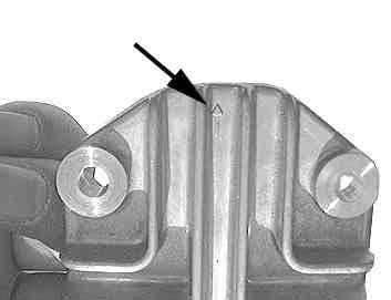

7 Remove the rocker arm shafts on the original cylinder head, and adjusting bolts and nuts on the rocker arm. Press in the guide roller so the center of the guide Install the cam-sprocket bolt into the camshaft. The roller and the guide-roller bolt hole on the cylinder camshaft will come out when you pull it out or strike its just mesh together. head lightly with a plastic hammer. Turning the camshaft, detach it. Do not pull it out by force. Attach a stopper plate of the kit and rocker arm to the Hold the cam chain by sticking the screwdriver cylinder head, with a stopper on the stopper plate facing through the cam chain into a middle hole on the to the right of the cylinder head. camshaft so the cam chain will not fall into the cylinder. Stopper Apply molybdenum solution to the original rocker arm shaft. And fix the rocker arm shaft, aligning the hole on the rocker arm with the one on the stopper plate, with the threaded portion of the rocker arm shaft facing out. Attach the cylinder-head cover gaskets and head cover. Apply engine oil to the removed adjusting bolt, which Install the guide roller bolt. (Fasten it only finger please install to the rocker arm of the kit. tight for now at this point.) Installation of cylinder head With thinner, degrease the cylinder head surface and upper surface of the cylinder. Heed the arrow showing which side should face downward. The arrow should face downward. Attach the cylinder side bolt. (Fasten it only finger tight for now at this point.) Apply engine oil to bearings at the tip on each side of the special cam shaft. Change of camshaft. Fix two dowel pins into the cylinder. Loosen tappet adjusting nuts and tappet adjusting bolts on the rocker arm in the cylinder head. At the time the tappet adjusting nuts are loosened, detach the tappet adjusting screws as well. Offset box wrench, 9mm Apply molybdenum solution to the cam top. Set the cam shaft on the cylinder head of the kit. Install the head gaskets Attach head-cover washers and nuts. With engine viewed from the front, attach the copper washer and three iron washers at the lower left, and hex nut and three cap nuts at the lower right. Copper washer Set the decompression cam so the stopper faces the combustion chamber. Pressing the tyre with a hand, fit the cylinder head into the stud bolts. Passing the cam chain through the cylinder head, install the cylinder head. Hex nut

 Socket, 10mm side cover of the kit, which please fix to the cylinder head Set the shaft so the cam top")

 shaft at TDC (Top Dead Center) on the compression stroke.")


 for lower and upper side bolts Installation of cam sprocket.")
8 Valve clearance (Intake side) Tighten the head nuts evenly. (If the torque wrench is not available, tighten them bit by bit securely and diagonally.) Tightening torque:12 N m (1.2 kgf m) Socket, 10mm side cover of the kit, which please fix to the cylinder head Set the shaft so the cam top faces the piston when the with two provided flange bolts, and tighten the bolts to cam sprocket bolt hole is turned toward the notch on the the specified torque. cylinder head. This arrangement places the cam Tightening torque: 10 N m (1.0 kgf m) shaft at TDC (Top Dead Center) on the compression stroke. Set the right-side cover gasket of the kit to the right Valve clearance (Exhaust side) Adjusting screw Thickness gauge Valve stem Attach a head side bolt. Fully tighten the guide roller bolts and the cylinder side bolts which were tightened temporarily. Open-end wrench, 10mm Offset box wrench, 10mm Install the dowel pin onto the camshaft. Remove a hex bolt next to the change-pedal shaft. As the tensioner, guiding the cam chain, will slacken, it will be easy to install the cam chain. Attach the cam chain to the camshaft so the O mark on the cam sprocket and the notch on the cylinder head mesh together. After installing the cap sprocket, fasten the bolt. Oil will flow out a little after the bolt is tightened. Wipe off the oil. Install the hex bolt which was next to the change pedal and was just removed. Tightening torque: 10 N m (1.0 kgf m) Offset box wrench, 10mm Adjustment of tappet clearance. Give the crankshaft more than two turns counterclockwise. First release the decompressing function, and then join together marks on the cam sprocket and on the cylinder head. While tightening a rocker arm s tappet adjusting Never rotate the crankshaft clockwise. Otherwise, screw, tighten the tappet adjusting nut to the extent the decompressor will work,making the valve that a 0.05 mm thickness gauge, placed between the clearance adjustment impossible. tappet adjusting screw and the valve stem end, can be pulled out with only a little resistance. If you have no idea of the proper resistance in pulling out the 0.05 Notch mm thickness gauge, then prepare a 0.07 mm and 0.03 mm thickness gauges. When the 0.07 mm gauge won't go in between the space but the 0.03 mm gauge goes in quite loosely, this means that roughly 0.05 mm clearance is secured. Set the space at 0.05 mm both for intake and exhaust. Notch Stamped O mark Cylinder head side Needle nose plier Offset box wrench, 9mm Thickness gauge Tightening torque: 10 N m (1.0 kgf m) for a guide roller bolt 10 N m (1.0 kgf m) for lower and upper side bolts Installation of cam sprocket. Notch After adjusting the tappet, turn the flywheel counterclockwise twice by hand, and then, align T and O marks each other. Never rotate the crankshaft clockwise. Otherwise, Flywheel side the decompressor will work,making the valve Turn the flywheel until the O mark on the cam sprocket clearance adjustment impossible. and the T mark on the flywheel mesh with each notch. Though the flywheel will not stop right at the required position because the magnet force repels each other, it is all right if O and T marks mesh with each notch at the same time. Align the T mark on the flywheel with the notch on the crankcase. Holding the flywheel, tighten up two cam sprocket bolts. Tightening torque: 9 N m (0.9 kgf m) Socket, 8mm Offset box wrench, 14mm Check if there is any change in the tappet clearance. If the clearance has not changed, there is no need to readjust it. However, in case there is a change, readjust the clearance.

 wrench.")


 Install three bolts to hold a crankcase left-side cover. Tightening torque: 10 N m (1.")


 head.")
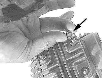
9 Installation of spark plug. In the case of bikes with frame Nos AB27-. install a hose on the storage tank. Install two tappet caps. Tightening torque: 12 N m (1.2 kgf m) Offset box wrench, 17mm Installation of cylinder head left-side cover. Install the plug with either an in-vehicle tool or plug Tightening torque: 26 N m (2.7 kgf m) wrench. Tightening torque: 11 N m (1.1 kgf m) Spark plug wrench Attach a plug cap to the plug. Installation of stock muffler. At this point, loosely install a hex bolt which holds the muffler. Fuel hose Socket, 12mm & Extension (medium) Fully tighten the loosely tightened nuts and bolts at three portions. Installation of stock carburetor. In the case of bikes with frame Nos Z50J-, check that an O-ring is attached to the inlet pipe. Air hose Attach fuel and air hoses. Installation of crankcase left-side cover. In installing the muffler, route the tail pipe inside the rear shock absorber first, and then run the flange close to the exhaust outlet of the cylinder head. Attach a cylinder-head left-side cover gaskets and left-side cover. Set the anti-rotation stopper of the left side cover to prevent the left-side cover from turning to the right when the bolt is being tightened. Install two flange collars, squeezing the exhaust pipe. Attach two bolts which hold the cylinder head and intake manifold. Offset box wrench, 8mm Tightening torque:10 N m (1.0 kgf m) Install three bolts to hold a crankcase left-side cover. Tightening torque: 10 N m (1.0 kgf m) Socket,8mm & Extension (short) Set the protrusion at the anti-rotation stopper. Tighten two nuts on the exhaust pipe loosely for now. Tightening torque: 10 N(1.0 kgf m) Open-end wrench, 10mm Install a bolt on the air-cleaner stay, fastening the bolt and earth jointly at the same time. See the figure below. Air cleaner Stay Earth Attach a change pedal. Tightening torque:10 N m (1.0 kgf m) Offset box wrench, 10mm Install a front fender. Frame for now. Tighten up a hex nut at the right side of the cylinder Tightening torque: 10 N m (1.0 kgf m) head. (The arrow marked nut is the hex nut in the above photo.) Socket, 10mm & Extension (medium) Tightening torque : 12 N m (1.2 kgf m) Socket, 10mm Attach a nut on the reverse side of the muffler loosely Socket, 10mm & Extension (medium) Bolt Tightening torque:10 N m (1.0 kgf m) Fasten two hex bolts on the reverse side of the front fender. Tightening torque: 10 N m (1.0 kgf m) Socket, 10mm & Extension (short) Pump the tyre. Check for slack in the bolts and the like fixed all the way from the engine to the suspension. Co.,Ltd Nishikiorihigashi Tondabayashi Osaka Japan TEL : FAX : URL :
10 Before riding: About fuel: High-octane gasoline should always be used. If there remains regular gasoline in the fuel tank, always replace it with high-octane gasoline. Additional hardware to be installed: For driving your bike with this kit installed, the following hardware need to be installed additionally. We disclaim all responsibility for any consequential and incidental damages or any other losses arising from the use of the provided products or parts, if your bike is not equipped with these additional hardware. Oil pump: The installation of this kit increases the heat release value of the engine, set off by the increase in power. The installation of Super Oil Pump is essential in order to circulate large amounts of oil and to help cool hardware and to alleviate the burden. Essential Super Oil Pump Clutch: The stock clutch cannot respond to the high engine power, and, therefore, causes clutch slippage, and consequently cannot transmit the engine power fully to the driving side. Therefore, it is necessary to install an essential clutch and heavy-duty clutch, including a special clutch. Change of sprocket: The installation of this kit will increase the power of your vehicle. So with the stock sprocket, you will find it uncomfortable to drive your bike because of too low gear, and will cause severe wears of hardware, not only adversely affecting the engine life, but also possibly breaking the engine in the worst case. Therefore, please replace the drive and driven sprockets to make the gear ratio high. Please note that a sprocket is not included in the kit. Furthermore, the gear ratio of the sprocket changes according to the clutch type and wheel size. The list below is just for your reference because the configuration in the list below needs to be changed according to the driver s weight, purpose of use, desire, taste and the like. When changing the driven sprocket, remove hardware around the rear wheel. Raise the rear wheel off the ground by placing a racing stand under the engine for safe work. Recommended sprocket for use with S-Stage, SCUT (with a driver weighing 65 kg) When the stock sprocket is changed to the recommended driven sprocket, the drive chain becomes too slack or too short. However, it is impossible to take up the slack of the drive chain just by adjusting the free play. You need to either shorten the chain by cutting it with a chain cutter, or to prepare a new drive chain. Especially, in the case of the Monkey, the length of chain changes according to the length of swing arm. For best performance: Carburetor Higher power can be attained through the installation of Big Bore Carburetor Kit suitable for each model of a bike for the best performance of S-Stage. Recommended Big Bore Carburetor Kit for S-Stage, SCUT Muffler Please install our TAKEGAWA-made various kinds of mufflers for higher power output. Oil cooler As a longtime high-load driving will further increase the heat release value of the engine, we recommend you to install an Oil Cooler Kit which keeps oil at appropriate temperatures and prevents such troubles as oil film shortage at high temperatures.
Instruction Manual for DOHC 4-VALVE HEAD PISTON / CYLINDER KIT
 Instruction Manual for DOHC 4-VALVE HEAD PISTON / CYLINDER KIT Thank you for purchasing one of our TAKEGAWA s products. These piston and cylinder kits are for exclusive use in a motorcycle equipped with
Instruction Manual for Super Head ST-1 & ST-2 CYLINDER KIT
 Instruction Manual for Super Head ST-1 & ST-2 CYLINDER KIT Item No. Fitting Ape, Ape100, XR50 Motard, and XR100 Motard SpecificationCompatible with a motorcycle equipped with a TAKEGAWA s ST-1 / ST-2 Super
Instruction Manual for
 Instruction Manual for Thank you for purchasing one of our TAKEGAWA-made products. Please strictly follow the following instructions in installing and using the kit. Before installing the kit, please be
Instruction Manual for 136cc SCUT Cylinder Kit
 Instruction Manual for 136cc SCUT Cylinder Kit Item No. Fitting Ape100, XR100 Motard, CRF100F, XR100R But limited tobikes fitted with TAKEGAWA s Super Head Thank you for purchasing one of our TAKEGAWA's
Cylinder Kit (124cc) Instruction Manual
 Instruction Manual") Cylinder Kit (124cc) Instruction Manual The ceramic-coated cylinder is used. (HA Cylinder) We coated the piston with molybdenum. Thank you for purchasing one of our products. These piston and cylinder
Cylinder Kit (124cc) Instruction Manual The ceramic-coated cylinder is used. (HA Cylinder) We coated the piston with molybdenum. Thank you for purchasing one of our products. These piston and cylinder
Kit Instruction Manual
 Kit Instruction Manual Thank you for purchasing one of our products. Please strictly follow the instruction to install and use the products. Before fitting the products, please be sure to check the contents
146cc SCUT Cylinder Kit Instruction Manual
 146cc SCUT Cylinder Kit Instruction Manual JP PAT. US PAT. The ceramic-coated cylinder is used. Item No. (Cylinder Kit) (Piston Kit) Fitting Ape100, XR100 Motard, CRF100F, XR100R But limited tobikes fitted
MIKUNI VM26 Carburetor Kit Instruction Manual
 MIKUNI VM26 Carburetor Kit Instruction Manual (For exclusive use in the Super Head 4VALVE+R-equipped motorcycle) Item No. (Carburetor set) AKEGAWA-made products. Please strictly follow the following instructions
Instruction Manual for CRF150F Hyper S-Stage Kit
 Instruction Manual for CRF150F Hyper S-Stage Kit Thank you for purchasing one of TAKEGAWA's products. Please strictly follow the following instructions in installing and using the products. Before fitting
Please read the following before installation. Points to notice about sounds
 Instruction Manual for / SCUT Cylinder Kit Thank you for purchasing one of Takegawa s products. This is a piston and cylinder kit for exclusive use in Super Head+R of Takegawa s make. You are kindly requested
Dry-Type Clutch Kit Instruction Manual (Cable-type)
") Dry-Type Clutch Kit Instruction Manual (Cable-type) Item No. Applicable models and frame No.: Monkey Gorilla (6V) Z50J-13000171805927 Monkey (12V) Monkey (FI) Gorilla (12V) Monkey BAJA Monkey RT Z50J-2000001
Dry-Type Clutch Kit Instruction Manual (Cable-type) Item No. Applicable models and frame No.: Monkey Gorilla (6V) Z50J-13000171805927 Monkey (12V) Monkey (FI) Gorilla (12V) Monkey BAJA Monkey RT Z50J-2000001
Instruction Manual for S-Stage KIT(125cc / SCUT)
") Instruction Manual for S-Stage KIT(125cc / SCUT) The ceramic-coated cylinder is used. We coated the piston with molybdenum. Item No. Applicable Models Frame Nos Ape100 HC07-1000001 XR100Motard HD13-1000001
Instruction Manual for S-Stage KIT(125cc / SCUT) The ceramic-coated cylinder is used. We coated the piston with molybdenum. Item No. Applicable Models Frame Nos Ape100 HC07-1000001 XR100Motard HD13-1000001
Instruction Manual for 4-Speed Close Gear Ratio Transmission Kit for XR / CRF50
 Instruction Manual for 4-Speed Close Gear Ratio Transmission Kit for XR / CRF50 Thank you for purchasing one of our TAKEGAWA s products. Please strictly follow the following instructions in installing
Magnesium Clutch Cover Kit Instruction Manual
 Magnesium Clutch Cover Kit Instruction Manual Item No. (Brown) Applied to Ape50 Ape50 (FI) Ape50 (FI Type D) AC18-1000001 Ape100 Ape100 Type D XR50 Motard XR100 Motard Frame Nos AC16-1000001 AC16-1600001
Aluminium Clutch Cover Kit Instruction Manual
 Aluminium Clutch Cover Kit Instruction Manual Item No. Applied to Ape50 Ape50 (FI) Ape50 (FI Type D) AC18-1000001 Ape100 Ape100 Type D XR50 Motard XR100 Motard Frame No. AC16-1000001 AC16-1600001 HC07-1000001
Special Crankcase set for Complete engine (4SMS)
") Special Crankcase set for Complete engine (4SMS) (Takegawa original stud pattern) (For 123cc only) (For 138cc only) (For SCUT 148cc only) Thank you for purchasing one of our products. This crankcase set
Special Crankcase set for Complete engine (4SMS) (Takegawa original stud pattern) (For 123cc only) (For 138cc only) (For SCUT 148cc only) Thank you for purchasing one of our products. This crankcase set
Instruction Manual for TAF 5-Speed Transmission Kit
 Instruction Manual for TAF 5-Speed Transmission Kit (For Dry type clutch ONLY) Thank you for purchasing one of our TAKEGAWA products. Please strictly follow the instructions to install and use the kit.
Instruction Manual Speed meter Kit for XR50 / XR100 Motard
 Thank you for purchasing one of our TAKEGAWA-made products. Please strictly follow the following instructions in installing and using the kit. Before installing the kit, please be sure to check the kit
TAF 5-Speed Transmission Kit Instruction Manual
 TAF 5-Speed Transmission Kit Instruction Manual Item No. Super Touring Super Street Fits Monkey and Gorilla Frame Nos Z50J-13000172699999 AB27-10000011899999 Thank you for purchasing one of our products.
Kit Instruction Manual
 Kit Instruction Manual Item No. Applicable models and frame Nos Monkey Z50J-2000001 AB27-1000001 Gorilla Z50J-2500001 AB27-1000001 Thank you for purchasing one of our TAKEGAWA's products. Please strictly
TAF 5-Speed Transmission Kit Instruction Manual
 TAF 5-Speed Transmission Kit Instruction Manual Item No. Thank you for purchasing one of our TAKEGAWA's products. Please strictly follow the following instructions in installing and using the Kit. Before
Instruction Manual for Black-Panel Speed Meter & Electric Tachometer
 Instruction Manual for lack-panel Speed Meter & Electric Tachometer (for 27 front fork) Thank you for purchasing one of our TAKEGAWA s products. Please read this instruction manual carefully to have a
Instruction Manual for FI Controller For Monkey (FI), Super Cub (FI), Little Cub (FI)
, Super Cub (FI), Little Cub (FI)") Instruction Manual for FI Controller For Monkey (FI), Super Cub (FI), Little Cub (FI) Item No. Fits & Frame Nos Monkey (FI)AB27-1900001 Super cub (FI)AA01-1700001 Little cub (FI)AA01-4000001 Thank you
Instruction Manual for FI Controller For Monkey (FI), Super Cub (FI), Little Cub (FI) Item No. Fits & Frame Nos Monkey (FI)AB27-1900001 Super cub (FI)AA01-1700001 Little cub (FI)AA01-4000001 Thank you
Instruction Manual for FI Controller
 Instruction Manual for FI Controller Thank you for purchasing one of our TAKEGAWA s products. Please strictly follow the instructions to install and use the products. Before installing the products, please
88cc Big Bore Kit Install Instructions
 88cc Big Bore Kit Install Instructions Before installing a big bore kit, you should first install a high volume oil pump. A high volume oil pump will deliver up to 300% more oil to your top end which will
Engine Complete KIT : Spec.SUPER HEAD + R
 Engine Complete KIT : Spec.SUPER HEAD + R (4SM-148) Secondary kick starter engine SUPER HEAD + R -148 5-Speed (Super street) O / P Item No. Compatible models Monkey / GorillaZ50J -2000001 AB27-10000011899999
Engine Complete KIT : Spec.SUPER HEAD 4VALVE + R
 Engine Complete KIT : Spec.SUPER HEAD 4VALVE + R (4SM-123) Secondary kick starter engine SUPER HEAD 4VALVE + R -123 5-Speed (Super street) O / P Item No. Compatible models Monkey / GorillaZ50J -2000001
HKS 700E. Service Manual June Ver. 2.04
 HKS 700E Service Manual 009 June Ver..04 HKS CO.,LTD 78 KITAYAMA FUJINOMIYA SHIZUOKA JAPAN 48-09 TEL +8(0)544-54-78 FAX +8(0)544-54-40 hks_aviation@hks-power.co.jp http://www.hks-power.co.jp/hks_aviation/
Engine Complete KIT : Spec.SUPER HEAD + R
 Engine Complete KIT : Spec.SUPER HEAD + R (CSM-148) Primary kick starter SUPER HEAD + R -148 5-Speed (Super street) O / P Item No. Compatible models Monkey / GorillaZ50J -2000001 AB27-10000011899999 Thank
26/01/2017 3GR-FSE ENGINE MECHANICAL: ENGINE UNIT: DISASSEMBLY; 2006 MY GS300 [01/ ]
![26/01/2017 3GR-FSE ENGINE MECHANICAL: ENGINE UNIT: DISASSEMBLY; 2006 MY GS300 [01/ ]](/thumbs/85/92233007.jpg "26/01/2017 3GR-FSE ENGINE MECHANICAL: ENGINE UNIT: DISASSEMBLY; 2006 MY GS300 [01/ ]") Last Modified: 8-24-2016 6.6 A Doc ID: RM000000T4X000X Model Year Start: 2006 Model: GS300 Prod Date Range: [01/2005 - ] Title: 3GR-FSE ENGINE MECHANICAL: ENGINE UNIT: DISASSEMBLY; 2006 MY GS300 [01/2005
Last Modified: 8-24-2016 6.6 A Doc ID: RM000000T4X000X Model Year Start: 2006 Model: GS300 Prod Date Range: [01/2005 - ] Title: 3GR-FSE ENGINE MECHANICAL: ENGINE UNIT: DISASSEMBLY; 2006 MY GS300 [01/2005
SE120R SCREAMIN' EAGLE PRO RACE-USE CRATE ENGINE
 -J007 REV. 00-09-08 SE0R SCREAMIN' EAGLE PRO RACE-USE CRATE ENGINE GENERAL Kit Number 90- Models For model fitment information, see the P&A Retail Catalog or the Parts and Accessories section of www.harley-davidson.com
Engine Dismantle and Assemble ( )
") Engine Dismantle and Assemble ( 34 8) Special Tools 5 053 Slide hammer 47 Vibration damper remover 47 5053 00 Splined head socket, cylinder head bolts 87 Mounting stand with geared drive 00 059C Installer
Engine Dismantle and Assemble ( 34 8) Special Tools 5 053 Slide hammer 47 Vibration damper remover 47 5053 00 Splined head socket, cylinder head bolts 87 Mounting stand with geared drive 00 059C Installer
7. CYLINDER HEAD/VALVES
 7 7 7-0 SERVICE INFORMATION...7-1 CYLINDER HEAD DISASSEMBLY...7-7 TROUBLESHOOTING...7-2 CYLINDER HEAD ASSEMBLY...7-8 CAMSHAFT REMOVAL...7-3 CYLINDER HEAD INSTALLATION...7-8 CYLINDER HEAD REMOVAL...7-5
MECHANICAL(H4DOTC DIESEL) > Cylinder Block INSTALLATION 1. After setting the cylinder block to ST, install the crankshaft bearing.
 > Cylinder Block INSTALLATION 1. After setting the cylinder block to ST, install the crankshaft bearing.") MECHANICAL(H4DOTC DIESEL) > Cylinder Block INSTALLATION 1. After setting the cylinder block to ST, install the crankshaft bearing. ST 499817100 ENGINE STAND Apply a coat of engine oil to the bearing and
MECHANICAL(H4DOTC DIESEL) > Cylinder Block INSTALLATION 1. After setting the cylinder block to ST, install the crankshaft bearing. ST 499817100 ENGINE STAND Apply a coat of engine oil to the bearing and
SMF / DSF / DTF SMF / DSF / DTF 200
 2006 SMF / DSF / DTF 200 1 The drawings in this parts book have been scaled so that parts can be easily recognized. 1 CYLINDER ASSY 2 CYLINDER ASSY Ref # Part # Description 1 410 0001A CYLINDER HEAD COVER
CHASSIS CONTENTS EXTERIOR PARTS 7-1 FRONT WHEEL 7-2 FRONT BRAKE 7-6 HANDLEBARS 7-13 FRONT FORK 7-15 STEERING 7-23 REAR WHEEL 7-26 REAR BRAKE 7-30
 CHASSIS CONTENTS EXTERIOR PARTS 7- FRONT WHEEL 7-2 FRONT BRAKE 7-6 HANDLEBARS 7-3 FRONT FORK 7-5 STEERING 7-23 REAR WHEEL 7-26 REAR BRAKE 7-30 REAR SHOCK ABSORBER 7-32 SWING ARM 7-33 7 7- CHASSIS EXTERIOR
CHASSIS CONTENTS EXTERIOR PARTS 6-1 FRAME COVER 6-2 REAR FRAME COVER 6-4 FRONT WHEEL 6-6 FRONT BRAKE 6-10 HANDLEBARS 6-17 FRONT FORK 6-19
 CHASSIS CONTENTS EXTERIOR PARTS 6- FRAME COVER 6- REAR FRAME COVER 6-4 FRONT WHEEL 6-6 FRONT BRAKE 6-0 HANDLEBARS 6-7 FRONT FORK 6-9 STEERING 6-6 REAR WHEEL 6-3 REAR BRAKE 6-39 6 REAR SHOCK ABSORBER 6-43
Engine Dismantle and Assemble ( )
") Engine Dismantle and Assemble (2 34 8) Special Tools 2-036A Remover for pilot bearing 2-37 Oil seal installer/aligner 237 2036A 2-044A Installer/Aligner, Pilot Bearing/Clutch Plate 244 2-44 Inlet manifold
Engine Dismantle and Assemble (2 34 8) Special Tools 2-036A Remover for pilot bearing 2-37 Oil seal installer/aligner 237 2036A 2-044A Installer/Aligner, Pilot Bearing/Clutch Plate 244 2-44 Inlet manifold
Timing Belt: Service and Repair
 2000 Hyundai Sonata L4-2.4L Page 1 Timing Belt: Service and Repair REMOVAL 1. Remove the crankshaft pulley, engine coolant pump pulley and drive belt. 2. Remove the timing belt cover. 2000 Hyundai Sonata
NOTES FOR SAFETY OPERATOR-ONLY.
 NOTES FOR SAFETY Both the parents and their child must fully understand everything in this manual before riding. This vehicle is for OPERATOR-ONLY. This vehicle is only designed for operation on level,
Honda Super Cub Etc. Frame & Forks
 Honda Super Cub Etc. Frame & Forks Introduction This section is all about how to strip, servioce and rebuild the frame and forks of the Honda Super Cub and other bikes using the same frames, plus all the
ENGINE MECHANICAL EM SECTION CONTENTS
 ENGINE MECHANICAL EM SECTION CONTENTS INTAKE MANIFOLD...EM-2 Component Parts Location...EM-2 Removal and Installation...EM-3 Inspection...EM-3 EXHAUST MANIFOLD...EM-4 Component Parts Location...EM-4 Removal
1. Remove the crankshaft pulley, engine coolant pump pulley and drive belt. 2. Remove the timing belt cover.
 DISASSEMBLY 1. Remove the crankshaft pulley, engine coolant pump pulley and drive belt. 2. Remove the timing belt cover. 3. Turn the crankshaft clockwise and align the timing marks so as to bring the No.
CAMSHAFT TIMING CHAIN, SPROCKET, AND TENSIONER REPLACEMENT
 Page 1 of 45 CAMSHAFT TIMING CHAIN, SPROCKET, AND TENSIONER REPLACEMENT Special Tools J 45027 Tensioner Tool J 45059 Angle Meter Page 2 of 45 Removal Procedure Page 3 of 45 Page 4 of 45 Page 5 of 45 Fig.
1. GENERAL INFORMATION
 GENERAL INFORMATION ENGINE SERIAL NUMBER ---------------------------------------------- - SPECIFICATIONS ---------------------------------------------------------- - 2 SERVICE PRECAUTIONS ------------------------------------------------
Remove Air Cleaner Cover and. Filter
 Remove Air Cleaner Cover and Inspect paper filter for tears Foam pre-cleaner is washable if equipped Replace if necessary Filter Remove Trim Panel Pull throttle lever knob off Remove 3, 8mm screws Remove
13. CRANKCASE/CRANKSHAFT/BALANCER/PISTON/CYLINDER
 13. CRANKCASE/CRANKSHAFT/BALANCER/PISTON/CYLINDER COMPONENT LOCATION 13-2 SERVICE INFORMATION 13-3 TROUBLESHOOTING 13-4 CRANKCASE SEPARATION 13-5 CRANKSHAFT 13-7 MAIN JOURNAL BEARING 13-9 CRANKPIN BEARING
VALVE CLEARANCE (K3-VE)
") ENGINE MECHANICAL VALVE CLEARANCE (K3-VE) 25 ENGINE MECHANICAL VALVE CLEARANCE (K3-VE) INSPECTION 1. DISCONNECT NEGATIVE BATTERY TERMINAL (See page RS-164.) 2. ROVE ENGINE UNDER COVER 3. DRAIN ENGINE COOLANT
ENGINE MECHANICAL VALVE CLEARANCE (K3-VE) 25 ENGINE MECHANICAL VALVE CLEARANCE (K3-VE) INSPECTION 1. DISCONNECT NEGATIVE BATTERY TERMINAL (See page RS-164.) 2. ROVE ENGINE UNDER COVER 3. DRAIN ENGINE COOLANT
Prerequisites: Shop Manual (recommended) pages 3-9 through 3-13.
 pages 3-9 through 3-13.") Prerequisites: Order your gaskets average about $25.00 bucks X 2 so $50.00 4NK-11193-00-00 Obtain a shim kit (Should have several 265 and 270s) (Some dealers will exchange) Obtain a Valve Bucket Tool YM-33961
Prerequisites: Order your gaskets average about $25.00 bucks X 2 so $50.00 4NK-11193-00-00 Obtain a shim kit (Should have several 265 and 270s) (Some dealers will exchange) Obtain a Valve Bucket Tool YM-33961
ENGINE CONTENTS CAUTION
 ENGINE CONTENTS ENGINE REMOVAL AND REINSTALLATION 3- ENGINE REMOVAL 3- ENGINE REINSTALLATION 3-7 ENGINE DISASSEMBLY 3-9 STARTER MOTER 3-9 THERMOSTAT 3-9 ND AIR VALVE 3-0 CYLINDER HEAD COVER 3-0 PISTON
BOTTOM END SERVICE TOOLS SERVICE PRODUCTS ENGINE, CVT AND GEARBOX Subsection 10 (BOTTOM END)
") BOTTOM END SERVICE TOOLS Description Part Number Page CRANKCASE SUPPORT MAG/PTO... 529 036 031... 151 CRANKSHAFT LOCKING BOLT... 529 035 617... 154 DRIVE SHAFT OIL SEAL INSTALLER... 529 036 028... 143
BOTTOM END SERVICE TOOLS Description Part Number Page CRANKCASE SUPPORT MAG/PTO... 529 036 031... 151 CRANKSHAFT LOCKING BOLT... 529 035 617... 154 DRIVE SHAFT OIL SEAL INSTALLER... 529 036 028... 143
<4D5> ENGINE Click on the applicable bookmark to selected the required model year
 ENGINE 11B-2 ENGINE General Information GENERAL INFORMATION 11100010339 Items 4D56 Total displacement m 2,477 Bore x Stroke mm 91.1 x 95.0 Compression ratio 21 Combustion chamber Camshaft
3. INSPECTION/ADJUSTMENT
 3 SERVICE INFORMATION...3-0 FINAL REDUCTION GEAR OIL...3-7 MAINTENANCE SCHEDULE...3-2 DRIVE BELT...3-7 FUEL FILTER...3-3 BRAKE SHOE...3-8 THROTTLE OPERATION...3-3 BRAKE ADJUSTING NUT...3-8 AIR CLEANER...3-4
ENGINE OVERHAUL <2.4L ENGINE>
 11B-1 GROUP 11B ENGINE OVERHAUL CONTENTS GENERAL SPECIFICATIONS 11B-2 SERVICE SPECIFICATIONS 11B-2 REWORK DIMENSIONS 11B-3 TORQUE SPECIFICATIONS 11B-4 SEALANTS 11B-7 SPECIAL TOOLS 11B-8 GENERATOR
Camshaft Timing Chain, Sprocket, And Tensioner Replacement
 2007 Pontiac Solstice - Engine Mechanical > Engine Mechanical - 2.0L > Repair Instructi... Page 1 of 29 2007 Pontiac Solstice : Engine Mechanical > Engine Mechanical - 2.0L > Repair Instructions - On Vehicle
May we, the manufacturer, take this opportunity to thank you for choosing our ATV to serve you.
 FOREWORD May we, the manufacturer, take this opportunity to thank you for choosing our ATV to serve you. This Owner s Manual is prepared for you the details as to operate and maintenance necessarily to
SSR200 Zongshen 200cc Dirt Bike (VIN PREVIX LZSJ)
") Page 1 of 19 Product Information Baja Web > Product Information > Parts Lists > DIRTBIKE > SSR200 Zongshen 200cc Dirt Bike (VIN PREVIX LZSJ) SSR200 Zongshen 200cc Dirt Bike (VIN PREVIX LZSJ) SSR200 Zongshen
Page 1 of 19 Product Information Baja Web > Product Information > Parts Lists > DIRTBIKE > SSR200 Zongshen 200cc Dirt Bike (VIN PREVIX LZSJ) SSR200 Zongshen 200cc Dirt Bike (VIN PREVIX LZSJ) SSR200 Zongshen
2012 Kia Soul L4 2.0L
 2012 Kia Soul L4 2.0L Vehicle» Engine, Cooling and Exhaust» Engine» Timing Chain» Service and Repair» Repair Procedures» Part 1 Removal Engine removal is not required for this procedure. CAUTION: Use fender
ENGINE OVERHAUL <2.4L ENGINE>
 11D-1 GROUP 11D ENGINE OVERHAUL CONTENTS GENERAL SPECIFICATIONS 11D-2 SERVICE SPECIFICATIONS 11D-2 REWORK DIMENSIONS 11D-3 TORQUE SPECIFICATIONS 11D-4 SEALANTS 11D-7 SPECIAL TOOLS 11D-8 GENERATOR
World Formula TECH MANUAL
 World Formula TECH MANUAL Section 1 General Rules 1. Only stock Briggs & Stratton World Formula Model # 124435-8101 will be used in this class except as provided in this Tech manual. All parts will be
15.Timing Chain Assembly
 15. A: REMOVAL 1. TIMING CHAIN RH When replacing a single part, perform the work with the engine assembly installed to body. 1) Remove the chain cover. 2) Using
BR-250 / BR-250SS / M2-250 SERVICE MANUAL
 BR-250 / BR-250SS / M2-250 SERVICE MANUAL Manufactured by PGO of Motive Power Industry Co., Ltd 1. INSPECTION/ADJUSTMENT 1 1 INSPECTION/ADJUSTMENT SERVICE INFORMATION -------------------------------------------------
HAMMERHEAD GT200. Page 1 of 9
 HAMMERHEAD GT200 Figue Part Number Description F1-1 M200-0101 CYLINDER HEAD SUBASSY F1-2 98056-57713-00 SPARK PLUG (C7HSA NGK) F1-3 M150-1001010 CYLINDER HEAD GASKET F1-4 M150-1001004 CARBURETOR INSULATOR
CAMSHAFT TIMING CHAIN, SPROCK... CAMSHAFT TIMING CHAIN, SPROCKET, AND TENSIONER REPLACEMENT (LE5 OR LE9) (ENGINE MECHANICAL - 2.2L OR 2.
 (ENGINE MECHANICAL - 2.2L OR 2.") CAMSHAFT TIMING CHAIN, SPROCK... CAMSHAFT TIMING CHAIN, SPROCKET, AND TENSIONER REPLACEMENT (LE5 OR LE9) (ENGINE MECHANICAL - 2.2L OR 2.4L) Document ID# 2133175 Camshaft Timing Chain, Sprocket, and Tensioner
CAMSHAFT TIMING CHAIN, SPROCK... CAMSHAFT TIMING CHAIN, SPROCKET, AND TENSIONER REPLACEMENT (LE5 OR LE9) (ENGINE MECHANICAL - 2.2L OR 2.4L) Document ID# 2133175 Camshaft Timing Chain, Sprocket, and Tensioner
20.Cylinder Block. Cylinder Block A: REMOVAL ME(H4DOTC)-63 ST CRANKSHAFT STOPPER
-63 ST CRANKSHAFT STOPPER") Cylinder Block MECHANICAL 20.Cylinder Block A: REMOVAL Before conducting this procedure, drain engine oil completely. 1) Remove the intake manifold. 2)
Cylinder Block MECHANICAL 20.Cylinder Block A: REMOVAL Before conducting this procedure, drain engine oil completely. 1) Remove the intake manifold. 2)
ENGINE OVERHAUL GROUP 11B 11B-1 CONTENTS GENERAL SPECIFICATIONS... 11B-2 OIL PAN AND TIMING CHAIN CASE... 11B-27 SERVICE SPECIFICATIONS...
 11B-1 GROUP 11B CONTENTS GENERAL SPECIFICATIONS 11B-2 SERVICE SPECIFICATIONS 11B-2 FASTENER TIGHTENING SPECIFICATIONS 11B-4 SEALANTS AND ADHESIVES 11B-7 SPECIAL TOOLS 11B-8 GENERATOR AND IGNITION SYSTEM
TWO STAGE SNOW ENGINE SERVICE MANUAL
 RESIDENTIAL PRODUCTS TWO STAGE SNOW ENGINE SERVICE MANUAL LC175FDS (265cc) LC180FDS (302cc) About this Manual This service manual was written expressly for Toro service technicians. The Toro Company has
Dealer Instructions for SETUP and PRE-DELIVERY SERVICE HS928K1 HS1332 SNOWBLOWERS
 Dealer Instructions for SETUP and PRE-DELIVERY SERVICE HS928K HS332 SNOWBLOWERS 20 American Honda Motor Co., Inc. All Rights Reserved PPD54294 (20.08) of 3 HS928K HS332 SNOWBLOWERS IMPORTANCE OF PROPER
ATV-50/90/100 I/II/V OWNER S MANUAL
 1 ATV-50/90/100 I/II/V OWNER S MANUAL FOREWORD May we, the manufacturer, take this opportunity to thank you for choosing our ATV to serve you. This Owner s Manual is prepared for you the details as to
Engine Construction and Principles of Operation
 Ch. 4 Engine Construction and Principles of Operation Gasoline Engine A gasoline fueled engine is a mechanism designed to transform chemical energy into mechanical energy It is an internal combustion engine.
ENGINE OVERHAUL <2.4L ENGINE>
 11B-1 GROUP 11B ENGINE OVERHAUL CONTENTS SPECIAL TOOLS 11B-2 GENERATOR AND IGNITION SYSTEM 11B-6 REMOVAL AND INSTALLATION 11B-6 EXHAUST MANIFOLD 11B-9 REMOVAL AND INSTALLATION 11B-9 TIMING
ENGINE CONTENTS ENGINE REMOVAL AND REINSTALLATION 3-1 ENGINE REMOVAL 3-1 ENGINE REINSTALLATION 3-5 ENGINE DISASSEMBLY 3-7 STARTER MOTER 3-7
 ENGINE CONTENTS ENGINE REMOVAL AND REINSTALLATION 3- ENGINE REMOVAL 3- ENGINE REINSTALLATION 3-5 ENGINE DISASSEMBLY 3-7 3 STARTER MOTER 3-7 CYLINDER HEAD COVER 3-8 PISTON 3- MAGNETO COVER 3-3 MAGNETO ROTOR
1.8L & 2.2L 4-CYL Article Text 1998 Subaru Impreza
 1.8L & 2.2L 4-CYL Article Text 1998 Subaru Impreza ARTICLE BEGINNING 1995-98 ENGINES Subaru - 1.8L & 2.2L 4-Cylinder 1995-97: Impreza (1.8L) 1995-98: Impreza (2.2L), Legacy (2.2L) * PLEASE READ THIS FIRST
2.Periodic Maintenance
 KYMCO MXU 500i/700i Repair Manual Periodic Maintenance 2.Periodic Maintenance This chapter covers the location and servicing of the periodic maintenance items for the KYMCO MXU 700i and MXU 500i models.
Timing Chain - Renew ( )
") «Scorpio '95 Table of Contents» «Section 21: Engine» «Subsection 21-05: 2,9 V6 24V Cosworth Engine» «REMOVAL AND INSTALLATION» Timing Chain - Renew (21 314 0) Special Tools 21-140-01Adaptor for 21-140
«Scorpio '95 Table of Contents» «Section 21: Engine» «Subsection 21-05: 2,9 V6 24V Cosworth Engine» «REMOVAL AND INSTALLATION» Timing Chain - Renew (21 314 0) Special Tools 21-140-01Adaptor for 21-140
Sisu S-Cam Drum Brakes
 Sisu S-Cam Drum Brakes (For hub reduction rear axles since 1992) Maintenance Manual Sisu Axles, Inc. Autotehtaantie 1 P.O. Box 189 FIN-13101 Hämeenlinna Finland Phone int + 358 204 55 2999 Fax int + 358
ENGINE CONTENTS ENGINE REMOVAL AND REINSTALLATION 3-1 ENGINE REMOVAL 3-1 ENGINE REINSTALLATION 3-5 ENGINE DISASSEMBLY 3-7 STARTER MOTER 3-7
 ENGINE CONTENTS ENGINE REMOVAL AND REINSTALLATION 3-1 ENGINE REMOVAL 3-1 ENGINE REINSTALLATION 3-5 ENGINE DISASSEMBLY 3-7 3 STARTER MOTER 3-7 CYLINDER HEAD COVER 3-8 PISTON 3-12 MAGNETO COVER 3-13 MAGNETO
GTS150. Dune Buggy MINIMUM RECOMMENDED OPERATOR AGE: FOR OFF-ROAD USE ONLY. 10th letter in VIN: D-G
 0-06 GTS50 0th letter in VIN: D-G Dune Buggy MINIMUM RECOMMENDED OPERATOR AGE: 6 FOR OFF-ROAD USE ONLY This vehicle is designed and manufactured for off-road use only. USA only: It does not conform to
CARBONETIC Carbon Clutch operating instructions
 ACROSS USA INC www.carbonetic.net TEL:310-635-3555 CARBONETIC Carbon Clutch operating instructions Thank you very much for your purchase of the CARBONETIC carbon clutch. Please read these instructions
Block & Side Cover 4-5. Crank, Piston & Rod 6-7. Cylinder Head 8-9. Cam & Valve train Carburetor / Manifold Flywheel & Ignition 14-15
 Table of Contents 2-1-2005 Title Page Block & Side Cover 4-5 Crank, Piston & Rod 6-7 Cylinder Head 8-9 Cam & Valve train 10-11 Carburetor / Manifold 12-13 Flywheel & Ignition 14-15 Assembly & 6 Packs 16
INSPECTION/ADJUSTMENT
 3 3 INSPECTION/ADJUSTMENT SERVICE INFORMATION----------------------------------------------------------------------- 3-1 MAINTENANCE SCHEDULE-------------------------------------------------------------------
ATS metal clutch (twin / triple) instruction manual for Nissan 350Z w/ HR motor 12 pages
 instruction manual for Nissan 350Z w/ HR motor 12 pages") ATS metal clutch (twin / triple) instruction manual for Nissan 350Z w/ HR motor 12 pages This instruction is provided by Performance Partners Intl 1 ATS Clutch operating instructions Thank you very much
ATS metal clutch (twin / triple) instruction manual for Nissan 350Z w/ HR motor 12 pages This instruction is provided by Performance Partners Intl 1 ATS Clutch operating instructions Thank you very much
Performer-Plus 5.0L Hydraulic Roller Lifter Camshaft only CATALOG #3722 MODEL: 5.0 Litre Ford V8, 1985 & later INSTRUCTIONS
 Performer-Plus 5.0L Hydraulic Roller Lifter Camshaft only CATALOG #3722 MODEL: 5.0 Litre Ford V8, 1985 & later INSTRUCTIONS PLEASE study these instructions carefully before installing your new camshaft.
CHASSIS CONTENTS EXTERIOR PARTS 6-1 FRONT WHEEL 6-2 FRONT BRAKE 6-6 HANDLEBARS 6-12 REAR WHEEL 6-30 REAR BRAKE 6-34 REAR SHOCK ABSORBER 6-36
 CHASSIS CONTENTS EXTERIOR PARTS 6-1 FRONT WHEEL 6-2 FRONT BRAKE 6-6 HANDLEBARS 6-12 FRONT FORK ( ) 6-14 FRONT FORK ( ) 6-20 STEERING 6-27 REAR WHEEL 6-30 REAR BRAKE 6-34 REAR SHOCK ABSORBER 6-36 6 SWING
DrVanos.com Stage II Installation Instructions. Tool rental is available with the purchase of a vanos kit *See website for more info*
 DrVanos.com Stage II Installation Instructions Special Tools Needed: Camshaft locking tool TDC Crank pin Sprocket turning tool Tool rental is available with the purchase of a vanos kit *See website for
11A-1 ENGINE CONTENTS ENGINE <4G9>...
 11A-1 ENGINE CONTENTS 11109000276 ENGINE ... ENGINE ... 11A 11B 11A-2 ENGINE CONTENTS GENERAL INFORMATION... 3 SERVICE SPECIFICATIONS... 3 SEALANTS... 4 SPECIAL TOOLS... 5 ON-VEHICLE SERVICE...
9-8 LEFT CRANKCASE COVER INSTALLATION ALTERNATORETARTER A TORIST ARTER CLUTCH. Install the dowel pin and a new gasket.
 ALTERNATORETARTER A TORIST ARTER CLUTCH LEFT CRANKCASE COVER INSTALLATION Install the dowel pin and a new gasket. Install the left crankcase cover. Install the washer and bolts, and tighten them securely.
ENGINE REMOVAL AND REINSTALLATION 3-1 ENGINE REMOVAL 3-1 ENGINE REINSTALLATION
 ENGINE CONTENTS ENGINE REMOVAL AND REINSTALLATION 3-1 ENGINE REMOVAL 3-1 ENGINE REINSTALLATION 3-5 ENGINE DISASSEMBLY 3-6 ENGINE COMPONENTS INSPECTION AND SERVICING 3-15 BEARINGS 3-15 OIL SEALS 3-15 CRANKSHAFT
The spacers can be made out of.750 round aluminum bar with a.3125 to.318 hole drilled in center.
 SECTION I : FRONT COVER INSTALLATION With Crankshaft, Camshaft and oil Galley plugs installed in engine, you need to verify that the front cover clears the oil galley plugs and fits on engine block. The
3. INSPECTION/ADJUSTMENT
 SERVICE INFORMATION...3-0 FINAL REDUCTION GEAR OIL...3-7 MAINTENANCE SCHEDULE...3-2 DRIVE BELT...3-7 FUEL FILTER...3-3 BRAKE SHOE...3-8 THROTTLE OPERATION...3-3 BRAKE ADJUSTING NUT...3-8 AIR CLEANER...3-4
Timing Chain Renew ( ) Renew. Section Title. Special Tools. Proprietary Tools Scraper Engine support bar
 Renew. Section Title. Special Tools. Proprietary Tools Scraper Engine support bar") Timing Chain Renew ( 34 0) Special Tools 40 400 40 Engine support bar 40 0 Adaptor for -40 40 03 Adaptor for -40 Proprietary Tools Scraper Workshop Equipment Transmission jack Materials Cable ties Sealer
Timing Chain Renew ( 34 0) Special Tools 40 400 40 Engine support bar 40 0 Adaptor for -40 40 03 Adaptor for -40 Proprietary Tools Scraper Workshop Equipment Transmission jack Materials Cable ties Sealer
E02 CYLINDER HEAD COVER ASSY
 TNG 150cc ZT E01 FAN COVER ASSY 1 BN0061-1 Clip 1 2 150ZT-E01.02 BN0064 Fan Cover 1 3 BN0061-2 Bracket 1 4 150ZT-E01.04 BN0064-4 Carburetor Cooling Duct 1 5 150ZT-E01.05 BN0064-3 Decorative Cover 1 6 150ZT-E01.06
TECHNICAL INFORMATION
 TECHNICAL INFORMATION Models No. Description EM2650UH/ EM2650LH, EM2651UH/ EM2651LH Petrol Brushcutter W W PRODUCT P 1/ 14 H CONCEPT AND MAIN APPLICATIONS These four 25.4mL Petrol Brushcutters have been
ENGINE MECHANICAL <4G69>
 11E-1 GROUP 11E ENGINE MECHANICAL CONTENTS SERVICE SPECIFICATIONS....... 11E-2 SEALANTS.................... 11E-2 SPECIAL TOOLS................ 11E-3 ON-VEHICLE SERVICE........... 11E-7 DRIVE BELT
CHASSIS CONTENTS FRONT WHEEL 6-1 FRONT BRAKE 6-6 FRONT FORK 6-14 STEERING STEM 6-20 REAR WHEEL AND REAR BRAKE 6-25 SUSPENSION 6-31 REAR SWING ARM 6-36
 CHASSIS CONTENTS FRONT WHEEL 6-1 FRONT BRAKE 6-6 FRONT FORK 6-14 STEERING STEM 6-20 REAR WHEEL AND REAR BRAKE 6-25 SUSPENSION 6-31 REAR SWING ARM 6-36 6 6-1 CHASSIS FRONT WHEEL REMOVAL Support the machine
3. INSPECTION/ADJUSTMENT
 3 3 INSPECTION/ADJUSTMENT SERVICE INFORMATION -------------------------------------------- 3-1 MAINTENANCE SCHEDULE ---------------------------------------- 3-2 FUEL LINE/FUEL FILTER -------------------------------------------
Valve gear, servicing
 Page 1 of 62 15-1 Valve gear, servicing WARNING! Do not re-use any fasteners that are worn or deformed in normal use. Some fasteners are designed to be used only once, and are unreliable and may fail if
3/17/2010 DX110. Baja Motorsports Inc. P.O. Box Phoenix, AZ Toll Free: PARTS AND PRICES ARE SUBJECT TO CHANGE 1 of 37
 DX110 Toll Free: 888-863-2252 PARTS AND PRICES ARE SUBJECT TO CHANGE 1 of 37 HANDLEBAR Part UPC Number Description Baja Description Qty. 1 DX110-100 883099101441 HANDLE BAR 1 2 DX-101 883099101458 LEFT
X150 National Extreme 150cc Atv (VIN PREFIX RKKG)
") Page 1 of 25 Product Information Baja Web > Product Information > Parts Lists > ATV > X150 National Extreme 150cc Atv (VIN PREFIX RKKG) X150 National Extreme 150cc Atv (VIN PREFIX RKKG) Cylinder Head [Image]
Page 1 of 25 Product Information Baja Web > Product Information > Parts Lists > ATV > X150 National Extreme 150cc Atv (VIN PREFIX RKKG) X150 National Extreme 150cc Atv (VIN PREFIX RKKG) Cylinder Head [Image]
VALCON PLUS V-CAM SYSTEM STEP 1 INSTRUCTION MANUAL
 VALCON PLUS V-CAM SYSTEM STEP 1 INSTRUCTION MANUAL NAME OF PRODUCT USE RB26 V-CAM SYSTEM STEP1 AUTOMOBILE PARTS PART NUMBER 22007-AN002 TYPE A MAKE ENGINE YEAR REMARKS 22007-AN003 TYPE B NISSAN SKYLINE