Block & Side Cover 4-5. Crank, Piston & Rod 6-7. Cylinder Head 8-9. Cam & Valve train Carburetor / Manifold Flywheel & Ignition 14-15
|
|
|
- Beatrix Ross
- 6 years ago
- Views:
Transcription
1
2 Table of Contents Title Page Block & Side Cover 4-5 Crank, Piston & Rod 6-7 Cylinder Head 8-9 Cam & Valve train Carburetor / Manifold Flywheel & Ignition Assembly & 6 Packs 16 Torque Values 17 Special Tools Pre-Assembly Cylinder Head Prep & Assembly 22 Final Assembly For more information about the F200 Concept and Rules or to find Resources for your YF200 R1 please visit: Page 3
3 Page 4
4 BLOCK & SIDE COVER YAMAHA YF200 R1 Ref # Burris P/N Description Qty 1 F Block / Crankcase with Sleeve 1 2 F Main Bearing 2 3 F Seal -Flywheel Side 1 4 F Oil Drain Plug - 10X16mm 1 5 F Oil Drain Plug Gasket 1 6 F Side Cover Dowel Pin -8mm 2 7 F Side Cover Complete 1 Includes 2,7,8,10,11,12,13, & 17 8 F Seal - PTO Side 1 9 F Side Cover Gasket 1 10 F Front Oil Filler Plug/Dip Stick 1 11 F Front Oil Filler Plug Gasket 1 12 F Rear Oil Filler Plug 1 13 F Rear Oil Filler Plug O-Ring 1 14 F Side Cover Stud - 8X25mm 6 15 F Side Cover Flange Nut - 8mm 6 16 F Cylinder Sleeve 1 17 F Rubber Side Cover Plug 1 Page 5
5 Page 6
6 CRANK, PISTON & ROD YAMAHA YF200 R1 Ref # Burris P/N Description Qty 1 F Crankshaft 1 2 F Connecting Rod Assy - Billet w/insert 1 F Bearing Insert For Billet Rod 1 F Rod Bolt & Washer Set 2 3 F Piston Assy - Std (71.00mm) 1 F Piston Assy " (71.05 mm) 1 F Piston Assy " (71.10 mm) 1 4 F Ring Set - Std (71.00mm) 1 F Ring Set (71.10mm) 1 5 F Wrist Pin 1 6 F Circlip (set of 2) 1 7 F Crank Shim (0.2mm) 1 F Crank Shim (0.3mm) 1 Page 7
7 Page 8
8 CYLINDER HEAD YAMAHA YF200 R1 Ref # Burris P/N Description Qty 0 F R1 Complete Gasket Kit w/.030 HG 1 F R1 Complete Gasket Kit w/.036 HG 1 F R1 Complete Gasket Kit w/.040 HG 1 1 F Cylinder Head - Bare 1 2 F Exhaust Header Stud - 6X15mm 2 3 F Intake Manifold Stud - 6X18mm 2 4 F Head Gasket -.030" 1 F Head Gasket -.036" 1 F Head Gasket -.040" 1 5 F Cylinder Head Stud - 8X55mm 2 6 F Cylinder Head Stud - 8X40mm 2 7 F Cylinder Head Dowel Pin -10mm 2 8 F Spark Plug NGK BPR6ES 1 9 F Exhaust Gasket 1 10 F Intake Gasket 1 11 F Exhaust Flange Nut - 6mm 2 F Intake Flange Nut - 6mm 2 12 F Cylinder Head Flange Nut - 8mm 4 13 F Valve Cover Baffle Gasket 1 14 F Valve Cover Gasket 1 15 F Valve Cover Baffle 1 16 F Valve Cover 1 19 F Valve Cover Stud & Nut Kit 1 (4) 6X15mm Stud, (4) 6mm Flange Nut, (4) Spacers Page 9
9 Page 10
10 CAM & VALVE TRAIN YAMAHA YF200 R1 Ref # Burris P/N Description Qty 1 F Camshaft - Unground Lobes 1 F Camshaft - 51 Grind 1 2 F Intake Valve - 26mm 1 3 F Exhaust Valve - 24mm 1 4 F Lifter 2 5-E F Valve Spring - Red (Exhaust) 1 5-I F Valve Spring - Blue (Intake) 1 5-E F PSI Valve Spring - Orange (Exhaust) 1 5-I F PSI Valve Spring - White (Intake) 1 6 F Valve Spring Retainer 2 7 F Valve Spring Ratainer Lock 2 8 F Rocker Arm 2 9 F Rocker Arm Pivot 2 10 F Rocker Arm Stud 2 11 F Rocker Arm Lock Nut 2 12 F Push Rod Guide Plate 1 13 F Push Rod (OEM) 2 13 F Push Rod Tubular.187 Diameter 2 14 F Intake Valve Stem Seal 1 Page 11
11 Page 12
12 CARBURETOR / MANIFOLD Recommended Carburetor Settings (Starting Point) Model Pop Off Low speed High Speed Carburetor.790 Venturi 10/11 psi 2 1 YAMAHA YF200 R1 Ref # Burris P/N Description Qty 1 F Carburetor.790 Venturi 1 2 F Filter Cup & Mounting Screws.790 Carb 1 3 F Intake Manifold W/ Nuts & Studs 1 4 F Air Filter 1 5 F Pre- Filter Wrap 1 6 F Linkage Kit With Hardware 1 7 F mm - (.551) Jr. I Restrictor Plate 1 F mm - (.630) Jr. II Restrictor Plate 1 F mm - (.709) Jr. III Restrictor Plate 1 8 F Carburetor Flange Gasket 1 Notes: (1) When adjusting the linkage make sure the throttle shutter (butterfly) fully closes. Also, do not set the shutter adjusting screw to idle the engine as this will cause it to run rich when decelerating or on warm up/parade laps and make proper LS adjustments difficult. Start the engine about 1 minute before going onto the track and gently crack the throttle to keep the engine running. (2) Adjust throttle linkage so it stops at the pedal, not the carburetor throttle shaft Page 13
13 Page 14
14 FLYWHEEL & IGNITION YAMAHA YF200 R1 Ref # Burris P/N Description Qty 1 F Fan Housing 1 2 F Fan Housing Flange Bolt - 6X12mm 4 3 F T.C.I. Mounting Flange Bolt - 6X20mm 2 4 F Spark Plug Cap 1 5 F T.C.I. Unit 1 6 F Flywheel Key (offset) 28 Advance 1 7 F Flywheel - OEM 1 8 F Flywheel Nut (Starter) 3/4" Hex 1 9 F Flywheel Screen 1 NOTES: Page 15
15 ASSEMBLY & 6 PACKS Ref # Burris P/N Description Qty 1 F Exhaust Stud & Flange Nut (kit) 1 (2) 6X15mm Stud, (2) 6mm Flange Nut 2 F Intake Stud & Flange Nut (kit) 1 (2) 6X18mm, (2) 6mm Flange Nut 3 F Cylinder Head Stud & Flange Nut (kit) 1 (2) 8X40mm Stud, (2) 8X55mm Stud, (4) 8mm Flange Nut 4 F Valve Cover Stud (kit) 1 (4) 6X15mm Stud, (4) 6mm Flange Nut, (4) Spacers 5 F Side Cover Stud & Flange Nut (kit) 1 (6) 8X25mm Stud, (6) 8mm Flange Nut 6 F Fan Houseing Flange Bolt (kit) 1 (4) 6X12mm Flange Bolt 7 F T.C.I. Mounting Flange Bolt (kit) 1 (2) 6X20mm Flange Bolt Ref # Burris P/N Description Qty 8 F Cylinder Head & Side Cover Flange Nut 6 8mm Flange Nut (six pack) 9 F Intake & Exhaust Flange Nut 6 6mm Flange nut (six pack) 10 F Cylinder Head Stud 6 8X40mm Stud (six pack) 11 F Cylinder Head Stud 6 8X55mm Stud (six pack) 12 F Side Cover Stud 6 8X25mm Stud (six pack) 13 F Intake Stud 6 6X18mm Stud (six pack) 14 F Exhaust Stud 6 6x15mm Stud (six pack) 15 F Cylinder Head Dowel Pin 6 10mm Dow el Pin (six pack) 16 F Side Cover Dowel Pin 6 8mm Dow el Pin (six pack) Page 16
16 TORQUE VALUES YAMAHA YF200 R1 Item in-lbs ft-lbs Nm m-kg Connecting Rod Bolts Side Cover Nuts Flywheel Nut Cylinder Head Nuts Rocker Arm Stud Rocker Arm Lock Nut Valve Cover Nuts T.C.I. Flange Bolts Flywheel Shroud Oil Drain Plug Intake Manifold Nuts Exhaust Manifold Nuts Spark Plug Page 17


17 SPECIAL TOOLS Page 18
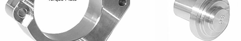
18 SPECIAL TOOLS YAMAHA YF200 R1 Ref # Burris P/N Description Qty 1 F Complete Tool Kit 1 Includes items 2,3,4,5,6,8 & 9 2 F Torque Plate 1 3 F Dowel Remover (8mm & 10mm) 1 4 F Seal Installer (Side Cover) 1 5 F Seal Installer (Block) 1 6 F Piston Installer (71.0mm & 71.05mm) 1 7 F Piston Installer (71.1mm & 71.20mm) 1 8 F mm Stud Installer 1 Intake, Exhaust, & Valve Cover 9 F mm Stud Installer 1 Side Cover & Head Note: It is strongly recommended you purchase the Complete Tool Kit (F ) when building your YF200 R1 engine. Possible component damage can occur during assembly without the proper tools. Page 19
19 Pre-Assembly Thoroughly clean and inspect parts prior to assembly for damage and compatibility Crank & Rod Prep: Check the crank journals for any nicks or scratches and remove them with a fine stone to prevent damage to the bearing seat areas. Check the rod bolt holes to be sure the bolts seat properly and burr or lap mating edges of connecting rod insert bearing to insure proper clearance. Cam Prep: Inspect the cam gear and lobes for burrs. If necessary, deburr & polish these areas. Thoroughly clean the cam to remove scale or blasting media left from the heat-treating process. Lapping the Block: Lap the cylinder head and motor mount surfaces on a surface plate to remove any burrs or irregularities. This will insure proper sealing for the head and also keep from binding the crank when the engine is attached to the motor mount. Fitting the Piston: Remove all sharp edges from piston with a deburring wheel or fine sand paper. Hone the block using a 280/400 grit stone to achieve piston to cylinder clearance (measure the piston 90 from the wrist pin and ¼ from the bottom). Finish the bore with a plateau hone using about 15/20 strokes. After the piston has been fitted clean the block with hot soapy water and spray the bore and bearing with WD-40 to prevent rust. Setting the Ring Gap: Note it is very important to follow the manufacturers recommended ring gap settings. Running too tight of a gap on the top and second rings will result in cylinder damage and cutting the expander on the oil ring will result in a loss in oil control. We have run the top 2 rings at.010+ gap and the oil rings as supplied for a full season with excellent results. (See piston ring instructions supplied with piston) Page 20


20 Pre-Assembly Seal Installation: The face of the seal should be.290 below the aluminum boss surface on the block and.200 on the side cover. When installing the seals it is important to apply grease on the O.D. to prevent scuffing or tearing of the seal. We have tools available (see Special Tools ) to install these seals that seat them at these predetermined depths. Stud Installation: Apply a small amount of (blue) Loctite to the threads of the dimpled end of the stud and install using a stud driver as shown. (see Special Tools ) Note-there are two different ends to the studs; dimpled and rounded install the dimpled end in the block. Run the stud down until it lightly bottoms and tighten it ¼ turn more. (An alternative method to the stud driver is to use a nut and jam nut) Dowel Installation: When installing the dowels be sure the holes are clean and they slide in easily. Place a small amount of grease on the dowels before installing them in the block, head and side cover. When removing the dowels, use the removal tool to eliminate the possibility of damage. (see Special Tools ). Page 21

21 Cylinder Head Prep & Assembly Cylinder Head Prep: Match and blend intake and exhaust ports with the valve bowls. Pay special attention to the intake runner where it enters the bowl as it is offset to promote swirl and needs to retain the offset in order to maintain the swirl characteristics. Next mount the intake manifold to the head and blend the junction. The outlet of the manifold has been purposely left a little undersize so that it can be increased to match the head. Note: the valve seats are finished at the factory so care must be taken not to damage or nick them during the porting operation. (You can mask them with duct tape) (Go to or for porting tools.) Valve Lapping and Seating: The valves and seats are ground from the factory and can be run as is without any problems or they can be lightly lapped with a fine lapping compound. Either way is acceptable. Cylinder Head Assembly: Thoroughly clean the head to remove grinding dust and lapping compound (if used). Before installing the rocker arm studs run them down onto their threaded holes to make sure they seat correctly against the hex. If they do not seat on the hex it will be necessary to run a 6X1.0 mm tap into the hole to clean up the thread. After this has been performed lay the push rod guide plate on the head with the guide tangs facing the combustion chamber. Place a small amount of (blue) Loctite on the coarse threads and screw in the rocker studs torque to 85 in/lbs. Install the appropriate 6mm studs on the intake and exhaust flanges. Use (blue) Loctite and run the stud down until it lightly bottoms and tighten it a ¼ turn more. Next, press the intake valve seal in place and install the valve using the blue spring. Install the exhaust valve using the red spring. Be sure to use a high-grade assembly lube on the valve stems. Now the head is ready for fitting to the block later on. Page 22
 Crankshaft: Slide the crankshaft into the flywheel side bearing.")
22 Final Assembly (From here until final assembly use an assembly lube on all sliding and rotating surfaces except the cylinder wall and rings which require normal crankcase oil.) Crankshaft: Slide the crankshaft into the flywheel side bearing. YAMAHA YF200 R1 Rod to Piston: Assemble the connecting rod to the piston and install the rings on the piston according to the manufacturer s instructions. (This procedure is very important to the performance and reliability of the engine and should be adhered to for best results.) Install Piston in Bore: Install the piston in the block using a solid piston installer (see Special Tools ) making sure that the rod is in a position that the dipper and the index mark on the rod line up when the cap is attached. (Note-Due to the fragile nature of the rings, collapsible type piston installers are not recommended.) Attach the cap with the dipper pointing down and torque the rod bolts to 150 in/lbs. (Go in 25 in/lbs increments starting at 75 in/lbs.) Install Lifters & Cam: Place the lifters in the block and install the cam with the timing marks lined up as shown. Side Cover: Install the locating dowels and side cover. Torque the bolts in a crisscross manner to 200 in/lbs in 25 in/lbs increments starting at 100 in/lbs. (Check for excessive crank endplay. Maximum is.020 ) Note: Thoroughly clean the gasket and gasket surfaces on the block and side cover prior to assembly. (Clean the gasket to remove any oil or lubricants with WD 40 and wipe clean. Brake Clean can be used on the block and side cover) Flywheel: Install the flywheel with the offset key in the advanced position and torque the special ¾ hex starter nut to 47 ft/lbs (564 in/lbs). Note: When changing bearings in the side cover or block it is necessary to use propane torch or oven to heat them during removal and installation. Page 23

 or back the stud off during adjustment.")
23 Final Assembly Cylinder Head: Install the locating dowels and the head gasket over the studs. Put the cylinder head in place and torque in a crisscross manner to 220 in/lbs in 25 in/lbs increments starting at 100 in/ lbs. Bring the piston to TDC on the compression stroke and drop in the pushrods. Install the rocker arms and set the lash at.004. Be careful not to over tighten the adjuster locknut (75 in/lbs) or back the stud off during adjustment. Place the valve cover assembly on the head, add the spacers to the studs and tighten to 50 in/lbs. Install the intake manifold, carburetor and exhaust header and tighten to 85 in/lbs. Note: With the supplied.040 thick head gasket the installed combustion chamber volume should be approximately 24.3 to 24.6 cc. Thinner head gaskets are available to adjust this if necessary.036 less.5cc and.030 less 1.0cc. Check the cylinder head section of this book for part numbers. Coil, Shroud and Spark Plug: Install the T.C.I.with a minimum of.022 air gap (use 3 different feeler gauges for example: =.022) torque coil mounting bolts to 85in/lbs. Install the shroud and tighten to 85 in/lbs. (Setting the air gap any closer DOES NOT improve performance and increases the risk of the flywheel magnets striking the coil.) Install the NKG BPR6ES spark plug and torque it to 160 in/lbs. (Note If the conditions dictate you may want to use the colder NGK BPR7ES spark plug.) Oil and Start: Add oz of the supplied oil and start the engine running it between 1800 and 2200 rpm for about 10 to 15 minutes. Break-in under a load is not necessary. (It may be necessary to lean the carburetor down during this process.) Immediately drain the oil and let the engine cool down. Check the torque settings on all the fasteners, adjust the valves, re-set the carburetor add new oil and you re ready to go. Page 24
24 Final Assembly Fuel: We recommend using 89/91 octane pump gas as these engines run well and tune easily with it. Higher octane race gas, besides being illegal, usually requires the timing to be advanced and carburetor to be leaned out to tune properly which in turn makes the engine run hotter and does not show an increase in power over the pump gas. Mounting: (1) We recommend the use of a 15 angle mount. This increases the flow of air to the cylinder head and also creates a sump for the oil to collect in. (2) Fuel filter should be mounted low (on the frame rail) and near the gas tank Page 25
25
World Formula TECH MANUAL
 World Formula TECH MANUAL Section 1 General Rules 1. Only stock Briggs & Stratton World Formula Model # 124435-8101 will be used in this class except as provided in this Tech manual. All parts will be
Briggs & Stratton Animal TECH MANUAL Version 1.6 Section 1 General Rules cannot Section 2 Required Modifications Section 3 Allowable Modifications
 Briggs & Stratton Animal TECH MANUAL Version 1.6 updated 2/ 7 / 2011 Section 1 General Rules 1. Only stock Briggs & Stratton Animal # 124332-8201and 124332-8203 - 01engine will be allowed in this class.
Local Option 206 Rules Manual Section 1 General Rules 1. Only stock Briggs & Stratton LO206 # engine will be allowed in this class.
 Local Option 206 Rules Manual Section 1 General Rules 1. Only stock Briggs & Stratton LO206 # 124332-8201engine will be allowed in this class. o All parts will be stock unaltered Briggs & Stratton Animal
460cc Do-It-Yourself Assembly Guide
 2995 Coleman St North Las Vegas, NV 89032 702-530-7753 702-643-7517 FAX VegasCarts.com 460cc Do-It-Yourself Assembly Guide *DIY Engines do not come with a warranty, these kits are intended for experienced
Briggs & Stratton. World Formula & Modified World Formula. Tech Manual
 Briggs & Stratton World Formula & Modified World Formula Tech Manual First Issued: May 22, 2007 Updated: January 2017 Jerry Mostek QMA Tech 2012 Quarter Midgets of America, Inc. WORLD FORMULA CLAIM RULE
2016 Rules and Regulations
 2016 Rules and Regulations Classes Adult Wing Junior II Wing Junior I Wing 641-204-9551 1102 E 8 th ST S Newton IA 50208 3-22-16 Amended 04/16/16 Cage Requirements Base Frames must be of kart configuration.
2018 Junior Sprint Rules
 2018 KidSprint Engine Rules Briggs World Formula 2018B All parts must be Briggs & Stratton factory production parts unless otherwise noted in these rules. No machining, polishing or alteration of any parts
420cc Builder Modified Predator OHV engine Technical Specifications 5/27/13
 BM (Builder Modified) Predator 420cc OHV engine With Electric Start Approved Engine: OHV Predator 420cc engine modified only according to these BM OHV Engine Spec. ENGINE SPEC SHEET FOR BM 420cc OHV CLASS
Kid Sprint Engine Rules Briggs World Formula
 Kid Sprint Engine Rules Briggs World Formula 2017 Jr Sprint Engine Rules Briggs World Formula effective 2/1/2017. All parts must bebriggs & Stratton factory production parts unless otherwise noted in these
KWIK SHOP GENERAL PREDATOR RULES 2019
 GENERAL PREDATOR RULES 2019 These rules are intended to keep the engine as Stock Out Of The Box as possible. There are no gray areas. If they do not specifically state that something is allowed, it will
KWIK SHOP PREDATOR HEMI CLASS 2018
 KWIK SHOP PREDATOR HEMI CLASS 2018 These rules are intended to keep the engine as Stock Out Of The Box As Possible. There are no gray areas. If they do not specifically state that something is allowed,
2019 SK Modified Open Engine Rules Supplement
 2019 SK Modified Open Engine Rules Supplement 20E- 5 GENERAL ENGINE REQUIREMENTS Engine must be OEM cast iron V8 production block, or the Dart SHP Block. Cylinder heads must be OEM or Dart 10024266, and
SPECIFICATIONS TEST AND ADJUSTMENT SPECIFICATIONS SPECIFICATIONS ENGINE FD620D, K SERIES
 TEST AND ADJUSTMENT Engine Oil Pressure Sensor Activates............................... 98 kpa (14.2 psi) Oil Pressure While Cranking (Minimum).......................... 28 kpa (4 psi) Oil Pressure.....................................
Briggs & Stratton! Animal. Tech Manual
 Briggs & Stratton Animal Tech Manual 1 st Edition April 15 th,2011 Updated: November 20, 2013 QMA National Technical Director: Rusty Barnard ANIMAL CLAIM RULE - For M SERIES QMA Type Engines 2012 Quarter
CYLINDER HEAD OVERHAUL
 ENGINE OVERHAUL PROCEDURES - GENERAL INFORMATION -2011 Mercedes-... Page 1 of 20 CYLINDER HEAD OVERHAUL * PLEASE READ THIS FIRST * Examples used in this article are general in nature and do not necessarily
Remove Air Cleaner Cover and. Filter
 Remove Air Cleaner Cover and Inspect paper filter for tears Foam pre-cleaner is washable if equipped Replace if necessary Filter Remove Trim Panel Pull throttle lever knob off Remove 3, 8mm screws Remove
NOVICE 1, 2 & JUNIOR 1 & 2 DIVISIONS
 NOVICE 1, 2 & JUNIOR 1 & 2 DIVISIONS 708 BRIGGS LOCAL OPTION 206 Briggs & Stratton (B&S) Model 124332 Type 8201 only. The intent of this class is to provide a sealed, simple-to-operate, ultra dependable
FORD V8 ENGINES 209. the treated area, the block is cracked and should be replaced.
 FORD V8 ENGINES 209 Cylinder block Core plug Strike here with hammer Drift 8 the treated area, the block is cracked and should be replaced. 3. Check flatness of the cylinder block deck. Place an accurate
RIDING PRODUCT ENGINE SERVICE MANUAL
 RESIDENTIAL PRODUCTS RIDING PRODUCT ENGINE SERVICE MANUAL LC1P92F (452cc) About this Manual This service manual was written expressly for Toro service technicians. The Toro Company has made every effort
SPECIFICATIONS TEST AND ADJUSTMENT SPECIFICATIONS SPECIFICATIONS ENGINE FD620D, K SERIES
 ENGINE FD620D, K SERIES SPECIFICATIONS SPECIFICATIONS TEST AND ADJUSTMENT SPECIFICATIONS Engine Oil Pressure Sensor Activates............................... 98 kpa (14.2 psi) Oil Pressure While Cranking
TWO STAGE SNOW ENGINE SERVICE MANUAL
 RESIDENTIAL PRODUCTS TWO STAGE SNOW ENGINE SERVICE MANUAL LC175FDS (265cc) LC180FDS (302cc) About this Manual This service manual was written expressly for Toro service technicians. The Toro Company has
Air Intake/Filtration
 Air Intake/Filtration Air Intake/Filtration Ref # Part Description Qty 25 048 -S CLEANER, AIR-CANISTER (includes 2-8) 2 25 096 06-S COVER ASSMBLY,AIR CLEANER (includes 3,4) 3 24 462 07-S VALVE, DUST EJECTOR
Not for Reproduction ADVANCE PRODUCT SERVICE INFORMATION APSI NO: 101 DATE: AUGUST SERIES UTILITY ENGINE 130G00 OHV HORIZONTAL SHAFT
 ADVANCE PRODUCT SERVICE INFORMATION APSI NO: 101 DATE: AUGUST 2014 SUBJECT: MODELS: 950 SERIES UTILITY ENGINE 130G00 OHV HORIZONTAL SHAFT This APSI provides basic servicing information in advance of the
365-SUB Engine : Engine Assembly 365-SUB [1/1] Page 1 of 5
![365-SUB Engine : Engine Assembly 365-SUB [1/1] Page 1 of 5](/thumbs/91/105185559.jpg "365-SUB Engine : Engine Assembly 365-SUB [1/1] Page 1 of 5") Page 1 of 5 1 951-11012 Bolt 2 951-11054 Valve Cover 2 951-11054 1 Valve Cover 3 731-07059 Breather Hose 4 726-04101 Hose Clamp 6 N/A 1 Intake Valve Spring Seat 7 751-11124 Pivot Locking Nut 7 751-11124
Page 1 of 5 1 951-11012 Bolt 2 951-11054 Valve Cover 2 951-11054 1 Valve Cover 3 731-07059 Breather Hose 4 726-04101 Hose Clamp 6 N/A 1 Intake Valve Spring Seat 7 751-11124 Pivot Locking Nut 7 751-11124
EdgePerformance AS 1417 & 1484 cc Big-Bore Kit Installation instructions
 EdgePerformance AS 1417 & 1484 cc Big-Bore Kit Installation instructions Kit components must be properly prepared before removing the old cylinders and pistons. If you ordered the quick-install option,
Model 16CG5AMQ
 Model 16CG5AMQ 1 16 2 7 27 53 35 22 16 2 32 15 33 30 13 19 17 12 3 3 37 6 29 7 36 50 2 25 36 5 31 21 20 51 1 10 1 39 5 0 3 9 3 9 1 2 5 52 11 6 26 1 Model 16CG5AMQ Ref. Part Number Description 1 61-0035-0637
ILLUSTRATED PARTS BOOK. 196cc Rear Tine Tiller Basic, EPA MODEL#: S-RTT-196-[E] Rev A200484
![ILLUSTRATED PARTS BOOK. 196cc Rear Tine Tiller Basic, EPA MODEL#: S-RTT-196-[E] Rev A200484](/thumbs/96/127772485.jpg "ILLUSTRATED PARTS BOOK. 196cc Rear Tine Tiller Basic, EPA MODEL#: S-RTT-196-[E] Rev A200484") ILLUSTRATED PARTS BOOK 196cc Rear Tine Tiller Basic, EPA MODEL#: S-RTT-196-[E] Rev. 2 20120711 1 A200484 Table of Contents Upper Handle Assembly 3 Base Assembly. 4-6 Parts List 7-10 Kit, Transmission Assembly
ILLUSTRATED PARTS BOOK 196cc Rear Tine Tiller Basic, EPA MODEL#: S-RTT-196-[E] Rev. 2 20120711 1 A200484 Table of Contents Upper Handle Assembly 3 Base Assembly. 4-6 Parts List 7-10 Kit, Transmission Assembly
9/7/2014 F9.9MSHV 1997 / CYLINDER CRANKCASE Yamaha Motor Corporation, U.S.A. All rights reserved.
 F9.9MSHV 997 Page of 45 9/7/04 F9.9MSHV 997 / CYLINDER CRANKCASE 04 Yamaha Motor Corporation, U.S.A. All rights reserved. F9.9MSHV 997 Page of 45 9/7/04 Part List F9.9MSHV 997 / CYLINDER CRANKCASE REF
Racing Performance Catalog & Reference Guide Model/Type:
 Version 4/08 Racing Performance Catalog & Reference Guide Model/Type: 124435 8105-01 Table of Contents SAFETY... 1 WORLD FORMULA General Specs...3 Special Tools...3 Torque Specs...3 Racing Specifics...3
1.6L 4-CYL - VIN [E]
![1.6L 4-CYL - VIN [E]](/thumbs/81/84172348.jpg "1.6L 4-CYL - VIN [E]") 1.6L 4-CYL - VIN [E] 1993 Nissan Sentra 1993 NISSAN ENGINES 1.6L 4-Cylinder NX, Sentra * PLEASE READ THIS FIRST * NOTE: For engine repair procedures not covered in this article, see ENGINE OVERHAUL PROCEDURES
1.6L 4-CYL - VIN [E] 1993 Nissan Sentra 1993 NISSAN ENGINES 1.6L 4-Cylinder NX, Sentra * PLEASE READ THIS FIRST * NOTE: For engine repair procedures not covered in this article, see ENGINE OVERHAUL PROCEDURES
7. CYLINDER HEAD/VALVES
 7 7 7-0 SERVICE INFORMATION...7-1 CYLINDER HEAD DISASSEMBLY...7-7 TROUBLESHOOTING...7-2 CYLINDER HEAD ASSEMBLY...7-8 CAMSHAFT REMOVAL...7-3 CYLINDER HEAD INSTALLATION...7-8 CYLINDER HEAD REMOVAL...7-5
ILLUSTRATED PARTS BOOK. 196cc Rear Tine Tiller MODEL#: P-RTT-196MD-[E] MODEL#: P-RTT-196MD
![ILLUSTRATED PARTS BOOK. 196cc Rear Tine Tiller MODEL#: P-RTT-196MD-[E] MODEL#: P-RTT-196MD](/thumbs/73/69164090.jpg "ILLUSTRATED PARTS BOOK. 196cc Rear Tine Tiller MODEL#: P-RTT-196MD-[E] MODEL#: P-RTT-196MD") ILLUSTRATED PARTS BOOK 196cc Rear Tine Tiller MODEL#: P-RTT-196MD-[E] MODEL#: P-RTT-196MD 1 Table of Contents Upper Handle Assembly... 3 Base Assembly... 4 Parts List... 5-6 Tines &Tine Shield... 7-8 Transmission...
ILLUSTRATED PARTS BOOK 196cc Rear Tine Tiller MODEL#: P-RTT-196MD-[E] MODEL#: P-RTT-196MD 1 Table of Contents Upper Handle Assembly... 3 Base Assembly... 4 Parts List... 5-6 Tines &Tine Shield... 7-8 Transmission...
GenX Street/Strip Cylinder Heads for the GM LT1
 GenX Street/Strip Cylinder Heads for the GM LT1 Thank you for purchasing Trick Flow GenX Street/Strip aluminum cylinder heads for the GM LT1. Please follow the steps outlined in this instruction manual
Petrol Engine 13hp PARTS BOOKLET MODEL: LF13
 Petrol Engine hp PARTS BOOKLET MODEL: LF Index Crankcase Assembly Crankcase Cover Assembly Cylinder Head & Cylinder Head Cover Assembly Crankshaft, Piston, Connecting & Balancing Shaft Combination of Camshaft
NATIONAL HOMOLOGATION FORM KARTING ENGINE
 NATIONAL HOMOLOGATION FORM KARTING ENGINE Manufacturer BRIGGS & STRATTON Make BRIGGS & STRATTON Model 206-124332 Validity of the homologation 6 years Number of pages 25 This Homologation Form reproduces
#100 TO #199 SPORTSMAN 1600 LIGHT BUGGY TECHNICAL SPECIFICATIONS
 #100 TO #199 SPORTSMAN 1600 LIGHT BUGGY TECHNICAL SPECIFICATIONS DEFINITION 1600 Light Buggy is a one-person, limited 4-wheel car using Volkswagen type 1 stock components with a 1585 cc engine. All parts
Introduction WISCONSIN ROBIN WR-WOI-21 OPM REV DATE: This catalog is designed to identify Wisconsin Robin parts.
 WISCONSIN ROBIN WR-WOI- OPM REV DATE: 0- Introduction This catalog is designed to identify Wisconsin Robin parts. When ordering parts, it is always advisable to list the engine model, specification number
LF2WP (-CA) WATER PUMP EXPLODED VIEWS & PARTS LISTS
 WATER PUMP EXPLODED VIEWS & PARTS LISTS") LFWP (-CA) WATER PUMP EXPLODED VIEWS & PARTS LISTS 0 Industrial Park Road Van Buren, AR 9 (8) - www.lifanpowerusa.com E- CRANKCASE ASSY 8 9 0 /8F /8F GB/T 80/8F 00/8F-E /8F 9/8F /8F GB/T 80/8F GB/T. /8F
LFWP (-CA) WATER PUMP EXPLODED VIEWS & PARTS LISTS 0 Industrial Park Road Van Buren, AR 9 (8) - www.lifanpowerusa.com E- CRANKCASE ASSY 8 9 0 /8F /8F GB/T 80/8F 00/8F-E /8F 9/8F /8F GB/T 80/8F GB/T. /8F
Edelbrock E-Force RPM Carburetor Supercharger C.I.D. Small-Block Chevy
 Edelbrock E-Force RPM Carburetor Supercharger 302-400 C.I.D. Small-Block Chevy 1986 and Earlier Style Heads: 1513, 1514, 15131, 15133, 15141, 15143 E-Tec and Vortec Style Heads: 1515, 1516, 15151, 15153,
Pro Iron Small Block - Technical Notes
 DART Pro Iron Small Block - Technical Notes Deck Height... 9.025" Bore... 4.00" or 4.125" unfinished Main Bearing Size... 350 (2.45") & 400 (2.65") Weight... 175 lbs Largest Recommended Bore... 4.165"
Illustrated Parts List
 FORM MS 4183 10/31/2006 REPLACES FORM MS 9748 7/1997 FILE IN SECT. 2 OF SERVICE MANUAL 290700 Illustrated Parts List Model Series 290700 TYPE NUMBERS 0100, 0102, 0106, 0107, 0108, 0333, 0402, 0410. TO
Air Intake/Filtration
 Air Intake/Filtration Air Intake/Filtration Ref # Part Description Qty 17 094 33-S BASE ASSY, AIR CLEANER CYCLONIC 1 17 083 03-S ELEMENT, AIR FILTER 1 25 086 223-S SCREW, M6 X18 1 17 096 80-S A/C COVER
5/30/2014 F2.5MSH 0407 / TOP COWLING Yamaha Motor Corporation, U.S.A. All rights reserved.
 F.5MSH 0407 Page of 40 5/30/04 F.5MSH 0407 / TOP COWLING 04 Yamaha Motor Corporation, U.S.A. All rights reserved. F.5MSH 0407 Page of 40 5/30/04 Part List F.5MSH 0407 / TOP COWLING REF - NO PART NUMBER
Valve gear, servicing
 Page 1 of 62 15-1 Valve gear, servicing WARNING! Do not re-use any fasteners that are worn or deformed in normal use. Some fasteners are designed to be used only once, and are unreliable and may fail if
Reproduction. Not for. Briggsracing.com. CORPORATION Briggs & Stratton Corporation MS /08
 Briggsracing.com MS-5702-4/08 BRIGGS&STRATTON CORPORATION Post office box 702 Milwaukee, WI 53201 USA 414 259 5333 2008 Briggs & Stratton Corporation Version 4/08 Racing Performance Catalog & Reference
9/7/2014 T9.9ELRZ 2001 / TOP COWLING Yamaha Motor Corporation, U.S.A. All rights reserved.
 T9.9ELRZ 00 Page of 56 9/7/0 T9.9ELRZ 00 / TOP COWLING 0 Yamaha Motor Corporation, U.S.A. All rights reserved. T9.9ELRZ 00 Page of 56 9/7/0 Part List T9.9ELRZ 00 / TOP COWLING REF - NO PART NUMBER PART
HONDA TECH MANUAL GX160 UT2 (ONLY) HONDA ENGINE RULES GENERAL RACING RULES SPECIFICALLY FOR 160 HONDA CLASS ONLY
 HONDA ENGINE RULES GENERAL RACING RULES SPECIFICALLY FOR 160 HONDA CLASS ONLY") HONDA TECH MANUAL GX160 UT2 (ONLY) HONDA ENGINE RULES GENERAL RACING RULES SPECIFICALLY FOR 160 HONDA CLASS ONLY Updated : February,2016 Jerry Mostek QMA Technical Director 1 HONDA CLAIM RULE - For GX160
HONDA TECH MANUAL GX160 UT2 (ONLY) HONDA ENGINE RULES GENERAL RACING RULES SPECIFICALLY FOR 160 HONDA CLASS ONLY Updated : February,2016 Jerry Mostek QMA Technical Director 1 HONDA CLAIM RULE - For GX160
Illustrated Parts List to
 Illustrated Parts List Vanguard Model Series 161400 to 161499 TYPE NUMBERS 0010 through 0036, 0040, 0041, 0047, 0049, 0051, 0070, 0073, 0079 through 0085, 0090, 0101, 0110 through 0135, 0199. FORM MS 9877
COLT 2310, 2510, AND 2712 COM PACT TRACTORS CHAPTER 9 TROUBLESHOOTING AND ANALYSIS
 COLT 2310, 2510, AND 2712 COM PACT TRACTORS CHAPTER 9 TROUBLESHOOTING AND ANALYSIS 9-A-1 UPON RECEIVING ANENGINE FORRE- PAIR. Learn the history of the unit from the customer. While the customer is present
TORC SERIES COMPETITION RULES FOR SPORTSMAN 1600 BUGGY
 TORC SERIES COMPETITION RULES FOR SPORTSMAN 1600 BUGGY DEFINED AS- A limited 4-wheel vehicle utilizing a type-1, 1600 c.c. Volkswagen air-cooled engine with one person in the vehicle. Division rules supersede
Valve Rocker Arm and Push Rod Installation (6.2L LS3)
") 9. Tighten the cylinder head bolts: 10.1. Tighten the M11 cylinder head bolts (1-10) a first pass in sequence to 30 N m (22 lb ft). 10.2. Tighten the M11 cylinder head bolts (1-10) a second pass in sequence
9. Tighten the cylinder head bolts: 10.1. Tighten the M11 cylinder head bolts (1-10) a first pass in sequence to 30 N m (22 lb ft). 10.2. Tighten the M11 cylinder head bolts (1-10) a second pass in sequence
PERFORMER-PLUS CAMSHAFT / LIFTERS / LUBE KIT CATALOG # 2103 MODEL: 400 c.i.d. Chevrolet V8 engines GENERAL INSTRUCTIONS
 PERFORMER-PLUS CAMSHAFT / LIFTERS / LUBE KIT CATALOG # 2103 MODEL: 400 c.i.d. Chevrolet V8 engines GENERAL INSTRUCTIONS Please study these instructions carefully before you remove your stock camshaft.
Skirted GEN III - Technical Notes
 DART Skirted GEN III - Technical Notes Deck Height... 9.240-9.450 STD or Raised cam, 9.750 9.950 Raised cam only Bore... 4.000 & 4.125 Main Bearing Size... LS-1 (2.558" 2.559") Weight... 115lbs 4.125 and
Ollie s Wholesale Price List
 ALIGN BORE MAINS DECK CYLINDER SURFACE 911-930 395.00 (head studs must be removed) 356-912 275.00 911-930 150.00 Thrust Cut 4 Cylinder 195.00 356-912 130.00 Inspection of Case 95.00 Remove Head Studs 80.00
SINGLE STAGE SNOW ENGINE SERVICE MANUAL
 RESIDENTIAL PRODUCTS SINGLE STAGE SNOW ENGINE SERVICE MANUAL LC154FS / LC154FDS (87cc) About this Manual This service manual was written expressly for Toro service technicians. The Toro Company has made
3 Inch Water Pump. SP-UG300. Owner s Manual
 Owner s Manual 3 Inch Water Pump SP-UG300 WARNING! To Reduce The Risk Of Injury, User Must Read And Understand Instruction Manual. www.steele-products.com CONTENTS SPECIFICATIONS... IMPORTANT SAFETY INFORMATION...
Table of Contents. 1. Safety Consideration and Warnings... Page Title Page... Page Remove Engine From Crate... Page 4
 Table of Contents 1. Safety Consideration and Warnings... Page 2 2. Title Page... Page 3 3. Remove Engine From Crate... Page 4 4. Prepare Engine For Race Kit Installation... Page 6 5. Top End... Page12
Counter-clockwise, view to output shaft Mixture 1:50, 2-stroke-oil, fuel min. 95 octane (RON)
") HIRTH 2703 Carburated - 55 hp The 2703 V is an air cooled, piston controlled 2-cylinder-inline-2-stroke engine with one or two carburetors and Nikasil coated cylinders. It has one of the highest power
HIRTH 2703 Carburated - 55 hp The 2703 V is an air cooled, piston controlled 2-cylinder-inline-2-stroke engine with one or two carburetors and Nikasil coated cylinders. It has one of the highest power
1983 BMW 320i. 1.8L 4-CYL 1983 Engines - 1.8L 4-Cylinder Engines - 1.8L 4-Cylinder
 ENGINE IDENTIFICATION 1.8L 4-CYL 1983 Engines - 1.8L 4-Cylinder For engine repair procedures not covered in this article, see ENGINE OVERHAUL PROCEDURES - GENERAL INFORMATION article in the GENERAL INFORMATION
420cc Gasoline Engine (G19)
") 0cc Gasoline Engine (G9) Parts Manual NOTICE! The information in this manual is known to be accurate as of the date of release shown on the cover. However, engineering changes can occur without notice.
0cc Gasoline Engine (G9) Parts Manual NOTICE! The information in this manual is known to be accurate as of the date of release shown on the cover. However, engineering changes can occur without notice.
Page 1 of HP B&S Vanguard Engine
 1405 Page 1 of 41 14 HP B&S Vanguard Engine 1405 Page 2 of 41 14 HP B&S Vanguard Engine Ref # Part Number Qty S/P/F Description BS-28Q777-0647-E1 1 14 HP B&S Vanguard Engine 1 BS-496412 1 Cylinder Assembly
ENGINE MEASUREMENTS ENGINE MEASUREMENTS AND SPECIFICATIONS CYLINDER HEAD. Measure Cylinder Compression. Using Telescoping Gauges and Hole Gauges
 ENGINE MEASUREMENTS AND SPECIFICATIONS Tool List Qty. Required Compression Gauge, 20 kgf/cm²: E-Z-GO Part No. N/A... 1 Compression Gauge Adapter, M14 1.25: E-Z-GO Part No. N/A... 1 Valve Seat Cutter, 45-35
General Engine Rules Common to all Makes:
 NEEDMORE SPEEDWAY 2017 CRATE LATE MODEL ENGINE RULES Engine in car must match manufacturer of body used. Example: Ford Thunderbird must run Ford Engine: Camaro must use Chevy Engine: Dodge Intrepid must
9/8/ MSHZ 2001 / TOP COWLING Yamaha Motor Corporation, U.S.A. All rights reserved.
 9.9MSHZ 00 Page of 47 9/8/04 9.9MSHZ 00 / TOP COWLING 04 Yamaha Motor Corporation, U.S.A. All rights reserved. 9.9MSHZ 00 Page of 47 9/8/04 Part List 9.9MSHZ 00 / TOP COWLING REF - NO PART NUMBER PART
HKS 700E. Service Manual June Ver. 2.04
 HKS 700E Service Manual 009 June Ver..04 HKS CO.,LTD 78 KITAYAMA FUJINOMIYA SHIZUOKA JAPAN 48-09 TEL +8(0)544-54-78 FAX +8(0)544-54-40 hks_aviation@hks-power.co.jp http://www.hks-power.co.jp/hks_aviation/
KARTSPORT NEW ZEALAND MANUAL BRIGGS & STRATTON LO206
 KARTSPORT NEW ZEALAND MANUAL N15 BRIGGS & STRATTON LO206 Issue 2017-1 published and effective 1-7-17 N15 BRIGGS & STRATTON LO206 N15.1 GENERAL SPECIFICATIONS N15.1.1 These engine specifications are under
122 Fasola Road, Sequim Wa (360) Morgan +4 Engine Rebuild Brochure
 Morgan +4 Engine Rebuild Brochure") 122 Fasola Road, Sequim Wa 98382 (360) 582-9020 Morgan +4 Engine Rebuild Brochure This brochure is intended to show the extensiveness of the work performed on the TR engines that I rebuild. I treat each
122 Fasola Road, Sequim Wa 98382 (360) 582-9020 Morgan +4 Engine Rebuild Brochure This brochure is intended to show the extensiveness of the work performed on the TR engines that I rebuild. I treat each
E02 CYLINDER HEAD COVER ASSY
 TNG 150cc ZT E01 FAN COVER ASSY 1 BN0061-1 Clip 1 2 150ZT-E01.02 BN0064 Fan Cover 1 3 BN0061-2 Bracket 1 4 150ZT-E01.04 BN0064-4 Carburetor Cooling Duct 1 5 150ZT-E01.05 BN0064-3 Decorative Cover 1 6 150ZT-E01.06
5/30/2014 F2.5LMHA 0313 / SCHEDULED SERVICE PARTS Yamaha Motor Corporation, U.S.A. All rights reserved.
 F.5LMHA 033 Page of 4 5/30/04 F.5LMHA 033 / SCHEDULED SERVICE PARTS 04 Yamaha Motor Corporation, U.S.A. All rights reserved. F.5LMHA 033 Page of 4 5/30/04 Part List F.5LMHA 033 / SCHEDULED SERVICE PARTS
TRU-POWER, INC. Product Line GENERAL PURPOSE ENGINE Model Name G400 Type QJ0 Mfg Section ENGINE Illustration CYLINDER HEAD - CYLINDER
 TRU-POWER, INC. Product Line GENERAL PURPOSE ENGINE Model Name G400 Type QJ0 Mfg Section ENGINE Illustration CYLINDER HEAD - CYLINDER 002 20-822-00 COVER, OIL PAN HOLE 00 003 2-822-000 GASKET, OIL PAN
Illustrated Parts List to
 Illustrated Parts List Model Series 124800 to 124899 FORM MS-2436-9/94 REPLACES FORM MS-2436-10/93 FILE IN SECT. 2 OF SERVICE MANUAL 124800 to 124899 TYPE NUMBERS 0106, 0206 through 0284, 0406 through
PARTS LIST MP4030EH/MP5030EH CONTENTS
 PARTS LIST MP4030EH/MP5030EH CONTENTS 1. MP4030EH MAIN BODY...1 ~ 2 2. MP5030EH MAIN BODY...3 ~ 4 3. MP4030EH/MP5030EH ENGINE (CRANKCASE)...5 ~ 6 4. MP4030EH/MP5030EH ENGINE (CRANKSHAFT, IGNITION COIL,
9/9/2014 F15MSHC 2004 / TOP COWLING Yamaha Motor Corporation, U.S.A. All rights reserved.
 F5MSHC 00 Page of 6 9/9/0 F5MSHC 00 / TOP COWLING 0 Yamaha Motor Corporation, U.S.A. All rights reserved. F5MSHC 00 Page of 6 9/9/0 Part List F5MSHC 00 / TOP COWLING REF - NO PART NUMBER PART NAME QUANTITY
Iron GEN III - Technical Notes
 DART Iron GEN III - Technical Notes Deck Height... 9.240" Bore... 4.000 & 4.125 Main Bearing Size... LS-1 (2.558" 2.559") Weight... 227lbs Largest Recommended Bore..... 4.185" Largest Recommended Crank
Counter-clockwise, view to output shaft Mixture 1:50, 2-stroke-oil, fuel min. 95 octane (RON)
") HIRTH 2703 Carburated - 55 hp The 2703 V is an air cooled, piston controlled 2-cylinder-inline-2-stroke engine with one or two carburetors and Nikasil coated cylinders. It has one of the highest power
HIRTH 2703 Carburated - 55 hp The 2703 V is an air cooled, piston controlled 2-cylinder-inline-2-stroke engine with one or two carburetors and Nikasil coated cylinders. It has one of the highest power
Screw, 5/16-18 x 2" (Use as required)
") H35-45614S Page 1 of 8 Engine Parts List #1 H35-45614S Page 2 of 8 Engine Parts List #1 1 34708A Cylinder (Incl. 2, 3 & 6) (2-1/2" Bor e) 2 26727 Pin, Dowel 3 27642 Pipe plug, 1/4-18 6 32600 Seal, Oil
H35-45614S Page 1 of 8 Engine Parts List #1 H35-45614S Page 2 of 8 Engine Parts List #1 1 34708A Cylinder (Incl. 2, 3 & 6) (2-1/2" Bor e) 2 26727 Pin, Dowel 3 27642 Pipe plug, 1/4-18 6 32600 Seal, Oil
GX200(SMG2) E-11 RECOIL STARTER (1)
 E-11 RECOIL STARTER (1)") E-11 RECOIL STARTER (1) 016 91406-166-000 CLIP, WIRE 1 1961501 016 91406-166-000 CLIP, WIRE 1 1961501 016 91406-671-000 CLIP, WIRE HARNESS 1 1937022 016 91406-671-000 CLIP, WIRE HARNESS 1 1961500 E-12
E-11 RECOIL STARTER (1) 016 91406-166-000 CLIP, WIRE 1 1961501 016 91406-166-000 CLIP, WIRE 1 1961501 016 91406-671-000 CLIP, WIRE HARNESS 1 1937022 016 91406-671-000 CLIP, WIRE HARNESS 1 1961500 E-12
OVERHAULING THE ENGINE. 85 Nm (8.5 m kg, 61 ft Ib) Order Job/Part Q ty Remarks Removing the drive sprocket
 Order Job/Part Q ty Remarks Removing the drive sprocket") INE EAS00188 INE DRIVE SPROCKET OVERHAULING THE INE 10 Nm (1.0 m kg, 7.2 ft Ib) 85 Nm (8.5 m kg, 61 ft Ib) Order Job/Part Q ty Remarks Removing the drive sprocket Remove the parts in the order listed.
INE EAS00188 INE DRIVE SPROCKET OVERHAULING THE INE 10 Nm (1.0 m kg, 7.2 ft Ib) 85 Nm (8.5 m kg, 61 ft Ib) Order Job/Part Q ty Remarks Removing the drive sprocket Remove the parts in the order listed.
FORD - Cyl Block and Related Parts
 FORD - Cyl Block and Related Parts Ref Description Qty All 302 Qty 351 Qty 351-HP 1 BLOCK ASSEMBLY 1 59-4046 1 59-4047 1 59-4047 2 PLUG - 1½ CUP - BRASS 6 59-4048 6 59-4048 6 59-4048 3 PLUG - OIL PASSAGE
DIAMO Discovery XLT PARTS CATALOG Engine First Edition August 2008
 DIAMO Discovery XLT PARTS CATALOG - 500 Engine First Edition August 2008 Copyright 2007-2008 LS MotorSports, LLC. Reproduction without written permission is completely forbidden. The information and diagrams
Owner s Manual. Parts List. Cylinder Head assy. APA Part No. Description Part. No
 Cylinder Head assy. A SP-GG900E-A-01-JD HEAD COVER COMP. BOLT JF340-A-01 SP-GG900E-A-02-JD HEAD COVER WASHER COMP. JF340-A-02 SP-GG900E-A-03-JD TUBE JF340-A-13 SP-GG900E-A-04-JD HEAD COVER COMP. JF340-A-04
E03 CYLINDER HEAD ASSY 1 BN0030 Dowel Pin 4
 E01 FAN COVER ASSY 1 BN0061-1 Clip 1 2 150ZT-E01.02 BN0064 Fan Cover 1 3 BN0061-2 Bracket 1 4 150ZT-E01.04 BN0064-4 Carburetor Cooling Duct 1 5 150ZT-E01.05 BN0064-3 Decorative Cover 1 6 150ZT-E01.06 BN0063-2
JULIAN GODFREY ENGINEERING LTD Labour Price List 6th April 2013
 LABOUR RATE LABOUR:117 LABOUR RATE PER HOUR 55.00 LABOUR:117.1 DAILY LABOUR RATE 605.00 LABOUR:118 PREP ENGINE FOR DYNO(inc. check ecu, loom, fit all sensors etc.) 55.00 LABOUR:118.1 FIT ENGINE TO DYNO,
Torque Specs - Main Caps w/thread lube 1-5 7/16" bolts 65 ft lbs 1 & 5 3/8" bolts 35 ft lbs
 DART Iron Small Block - Technical Notes Deck Height... 9.025" Bore... 4.00" or 4.125" unfinished Main Bearing Size... 350 (2.45") 400 (2.65") Weight... 205 lbs Largest Recommended Bore...... 4.185" Camshaft
ADVANCE PRODUCT SERVICE INFORMATION 76 05/01/2011 INTRODUCTION OF MODEL COMMERCIAL TURF SERIES AND PROFESSIONAL SERIES
 BRIGGS & STRATTON CORPORATION ADVANCE PRODUCT SERVICE INFORMATION APSI NO: DATE: SUBJECT: 76 05/01/2011 INTRODUCTION OF MODEL 490000 COMMERCIAL TURF SERIES AND PROFESSIONAL SERIES MODELS: 810 cc 49G500
SECTION C Engine 5.4L (4V)
") 303-01C-i Engine 5.4L (4V) 303-01C-i SECTION 303-01C Engine 5.4L (4V) CONTENTS PAGE SPECIFICATIONS... 303-01C-2 303-01C-2 Engine 5.4L (4V) 303-01C-2 SPECIFICATIONS Material Motorcraft Metal Surface Prep
303-01C-i Engine 5.4L (4V) 303-01C-i SECTION 303-01C Engine 5.4L (4V) CONTENTS PAGE SPECIFICATIONS... 303-01C-2 303-01C-2 Engine 5.4L (4V) 303-01C-2 SPECIFICATIONS Material Motorcraft Metal Surface Prep
1 of 25 9/19/2016 1:07 PM
 1 of 25 9/19/2016 1:07 PM GX610(VD) E-11 RECOIL STARTER 001 28400-ZE3-W01ZA STARTER ASSY., RECOIL *R8 * 1 002 28410-ZE3-W01ZA CASE COMP., RECOIL STARTER *R8 * 1 003 28421-ZE3-W01 PULLEY, RECOIL STARTER
GENERAL INSTRUCTIONS. PERFORMER-PLUS CAMSHAFT / LIFTERS / LUBE KIT MODEL: c.i.d. Chevrolet V8 Engines CATALOG #2117
 Page 1 PERFORMER-PLUS CAMSHAFT / LIFTERS / LUBE KIT MODEL: 283-400 c.i.d. Chevrolet V8 Engines GENERAL INSTRUCTIONS PLEASE study these instructions carefully before beginning this installation. Most installations
Illustrated Parts List to
 TYPE NUMBERS 0101, 0102, 0106, 0108, 0109, 0115 through 0224, 0415, 0418, 0467, 0468, 0601 through 0683, 3101 through 3108, 3110 through 3163, 3167 through 3181. Illustrated Parts List Model Series 124700
Craftsman Snow Thrower Model PARTS LIST
 Craftsman Snow Thrower Model 24.881900 PARTS LIST 11 13 3 2 24 9 1 18 4 2 1 20 23 1 14 1 9 2 4 4 4 3 28 8 3 4 3 39 0 3 43 38 2 48 2 42 1 41 40 49 4 44 31 4 31 21 29 34 9 19 10 32 22 2 Craftsman Snow Thrower
Eclatés Moteur G 200 F-V. 1/18
 Eclatés Moteur G 200 F-V www.francepower.fr 1/18 CYLINDER HEAD 1 120080276-0001 HEAD COMP.,CYLINDER 1 B 2 380180093-0001 BOLT, STUD, IN. 2 C 3 380600117-0001 PIN, DOWEL 2 C 4 120150070-0001 GASKET, CYLINDER
Illustrated Parts List Industrial/Commercial to
 FORM MS-9479 6/95 REPLACES FORM MS-9479 10/94 FILE IN SECT. 2 OF SERVICE MANUAL 402700 to 402799 Illustrated Parts List Industrial/Commercial Model Series 402700 to 402799 TYPE NUMBERS 1115 through 1117,
90 Y-12 Youth. Model Number A2005H4B2BUSR (Red) Model Number A2005H4B2BUSZ (Cat Green) Illustrated Parts Manual
 Model Number A2005H4B2BUSZ (Cat Green) Illustrated Parts Manual") 90 Y-12 Youth Model Number A2005H4B2BUSR (Red) Model Number A2005H4B2BUSZ (Cat Green) Illustrated Parts Manual 2005 TABLE OF CONTENTS 2005 ATV 90 Y-12 Youth Red (Model No. A2005H4B2BUSR) Cat Green (Model
90 Y-12 Youth Model Number A2005H4B2BUSR (Red) Model Number A2005H4B2BUSZ (Cat Green) Illustrated Parts Manual 2005 TABLE OF CONTENTS 2005 ATV 90 Y-12 Youth Red (Model No. A2005H4B2BUSR) Cat Green (Model
Quantity SC3000GB(E) SC4000GB(E) SC5000GB(E) SC5000GB3(E) 1
 SC4000GB(E) SC5000GB(E) SC5000GB3(E) 1") 0 Cylinder Head SCE080000 Head comp., cylinder SCE0000 Head comp., cylinder SCE05500 Plug, spark 3 SCE080000 Cover comp., head 4 SCE080050 Bolt, head cover 5 SCE080060 Washer, head cover 6 SCE08000 Guide,
0 Cylinder Head SCE080000 Head comp., cylinder SCE0000 Head comp., cylinder SCE05500 Plug, spark 3 SCE080000 Cover comp., head 4 SCE080050 Bolt, head cover 5 SCE080060 Washer, head cover 6 SCE08000 Guide,
1 of 20 11/10/2016 4:56 PM
 1 of 20 11/10/2016 4:56 PM E-11 RECOIL STARTER (1) 001 28400-ZH8-013YA STARTER ASSY., RECOIL *R280 * 1 001 28400-ZH8-013YA STARTER ASSY., RECOIL *R280 * 1 1936894 001 28400-ZH8-013ZA STARTER ASSY., RECOIL
DIAMO TURISTA 300CC ENGINE PARTS CATALOG. Second Edition March 2008
 DIAMO TURISTA 300CC ENGINE PARTS CATALOG Second Edition March 2008 Copyright 2004-2008 LS MotorSports, LLC. Reproduction without written permission is completely forbidden. The information and diagrams
INSTALLATION INSTRUCTIONS
 PERFORMER RPM CAMSHAFT / LIFTERS / LUBE KIT For 343-401 c.i.d. AMC V8 Engines CATALOG # 7132 INSTALLATION INSTRUCTIONS PLEASE study these instructions carefully before beginning this installation. Most
ATV 50 DVX BLACK-RED (A2008KSA2BUSD) Page 1 of 60 AIR INTAKE ASSEMBLY
 Page 1 of 60 AIR INTAKE ASSEMBLY") 2008 ATV 50 DVX BLACK-RED (A2008KSA2BUSD) Page 1 of 60 AIR INTAKE ASSEMBLY 2008 ATV 50 DVX BLACK-RED (A2008KSA2BUSD) Page 2 of 60 AIR INTAKE ASSEMBLY Ref # Part Number Qty S/P/F Description 1 3303-005
2008 ATV 50 DVX BLACK-RED (A2008KSA2BUSD) Page 1 of 60 AIR INTAKE ASSEMBLY 2008 ATV 50 DVX BLACK-RED (A2008KSA2BUSD) Page 2 of 60 AIR INTAKE ASSEMBLY Ref # Part Number Qty S/P/F Description 1 3303-005
Screw, 5/16-18 x 2" (Use as required)
") H30-35374S Page 1 of 8 Engine Parts List #1 H30-35374S Page 2 of 8 Engine Parts List #1 1 34708A Cylinder (Incl. 2, 3 & 6) (2-1/2" Bor e) 2 26727 Pin, Dowel 3 27642 Pipe plug, 1/4-18 6 32600 Seal, Oil
H30-35374S Page 1 of 8 Engine Parts List #1 H30-35374S Page 2 of 8 Engine Parts List #1 1 34708A Cylinder (Incl. 2, 3 & 6) (2-1/2" Bor e) 2 26727 Pin, Dowel 3 27642 Pipe plug, 1/4-18 6 32600 Seal, Oil
SECTION B Engine 5.0L (4V)
") 303-01B-i Engine 5.0L (4V) 303-01B-i SECTION 303-01B Engine 5.0L (4V) CONTENTS PAGE SPECIFICATIONS... 303-01B-2 303-01B-2 Engine 5.0L (4V) 303-01B-2 SPECIFICATIONS Material Motorcraft Metal Surface Prep
303-01B-i Engine 5.0L (4V) 303-01B-i SECTION 303-01B Engine 5.0L (4V) CONTENTS PAGE SPECIFICATIONS... 303-01B-2 303-01B-2 Engine 5.0L (4V) 303-01B-2 SPECIFICATIONS Material Motorcraft Metal Surface Prep