Mirrored from:
|
|
|
- Madison Henry
- 5 years ago
- Views:
Transcription
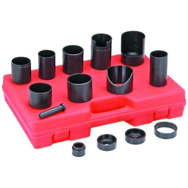
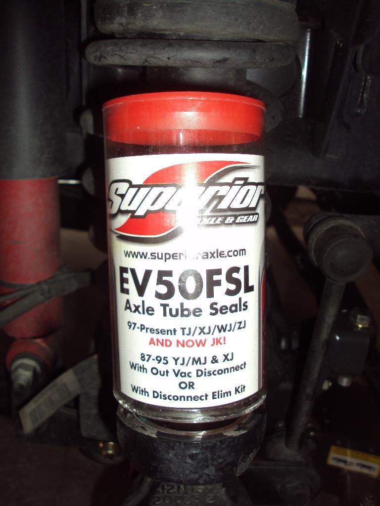
1 Mirrored from: , 02:43 AM #1 SilverSport Supporting Member WF Supporting Member Install Synergy Suspension Ball Joints Write-up Thanks to this forum, it didn't take me long to decide to ditch the crappy factory ball joints for something better: Synergy Suspension ball joints. I tried to put the entire install in one thread but the site only allows a maximum of 15 images in a thread so I broke it down into 4 threads. Vehicle 2011 Rubicon Unlimited Join Date: May 2011 Posts: 22,234 Garage Tools & Supplies 2-3 pound hammer Pair of jackstands Floor jack 1/2" drive breaker bar 1/2" drive ratchet 1/2" drive extensions 1/2" drive 21mm socket 1/2" drive 13mm 12 point socket Torque wrench 5mm allen wrench Small flat blade screwdriver 7/8", 1-1/16", and 1-1/8" combination wrenches or sockets 5/16" socket or combination wrench Diagonal pliers Anti-seize Wire Brush or Dremel 180 or 240 grit sandpaper Ball joint press Adapter set Bungee cord or zip ties Rubber mallet or deadlblow hammer New ball joints Brake cleaner Rags Extreme pressure moly grease Notes A. If you do this indoors make sure you allow at least 4 feet of space on the passenger side so you have room to remove the axle shaft and hub assembly. B. The upper ball joint is pressed out/in from the top. C. The lower ball joint is pressed in/out from the bottom. D. I also installed axle tube seals at the same time.

 Remove wheel/tire and set it out of the way.")
2 Steps 1) Place the transmission in Park or 1st. Set the parking brake. Start on one side and loosen the wheel nuts. Raise the front of the Jeep and place a jackstand under the axle tube just inside of the axle 'C'. 2) Remove wheel/tire and set it out of the way. 3) Unclip the wheel speed sensor harness from the brake hose and upper ball joint bracket.


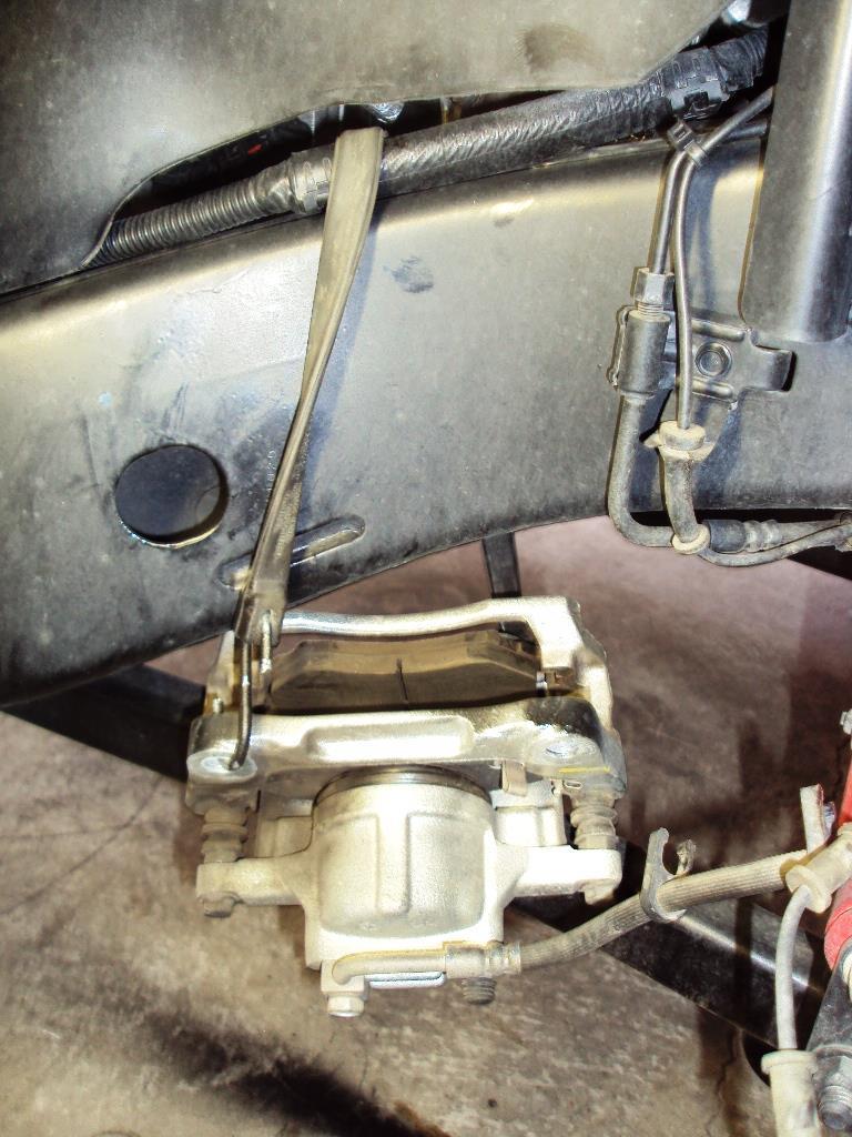
3 4) Remove the two 21mm bolts that hold the caliper assembly to the knuckle. Slide the caliper off the rotor and hang it from the frame with a bungee cord or zip ties. DO NOT LET THE CALIPER HANG BY THE BRAKE HOSE! Remove the rotor and set it aside.
4


5 5) Remove the bolt that hold the wheel speed sensor to the hub bearing but do not remove sensor at this time. 6) Using a 13mm 12 pint socket, remove the three bolts on the back side of the knuckle that mount the hub assembly to the knuckle.


6 7) Rap the outer edge of the hub assembly with a rubber mallet or dead blow hammer and pull it out from the knuckle a few inches.


7 8) Carefully remove the wheel speed sensor from the hub and pass it through the slot in the backing plate. Hang the harness and sensor on the brake caliper. Treat the sensor gently as it can be easily broken or damaged.

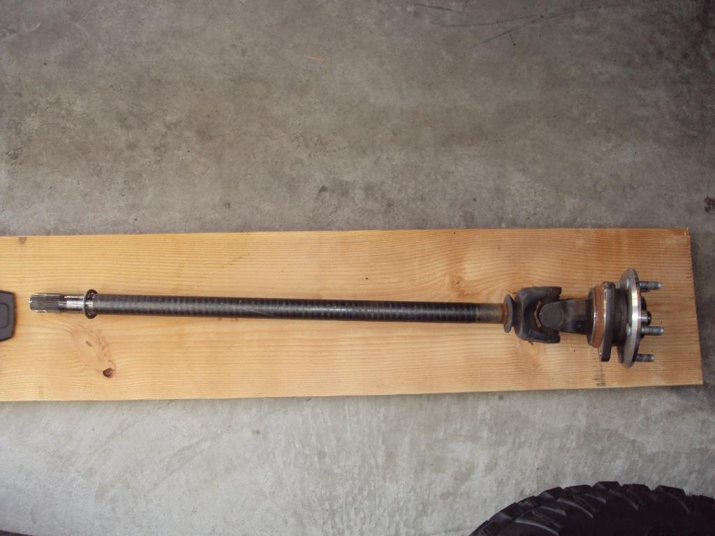
8 9) Pull the axle shaft completely out and set it on a clean surface.
9


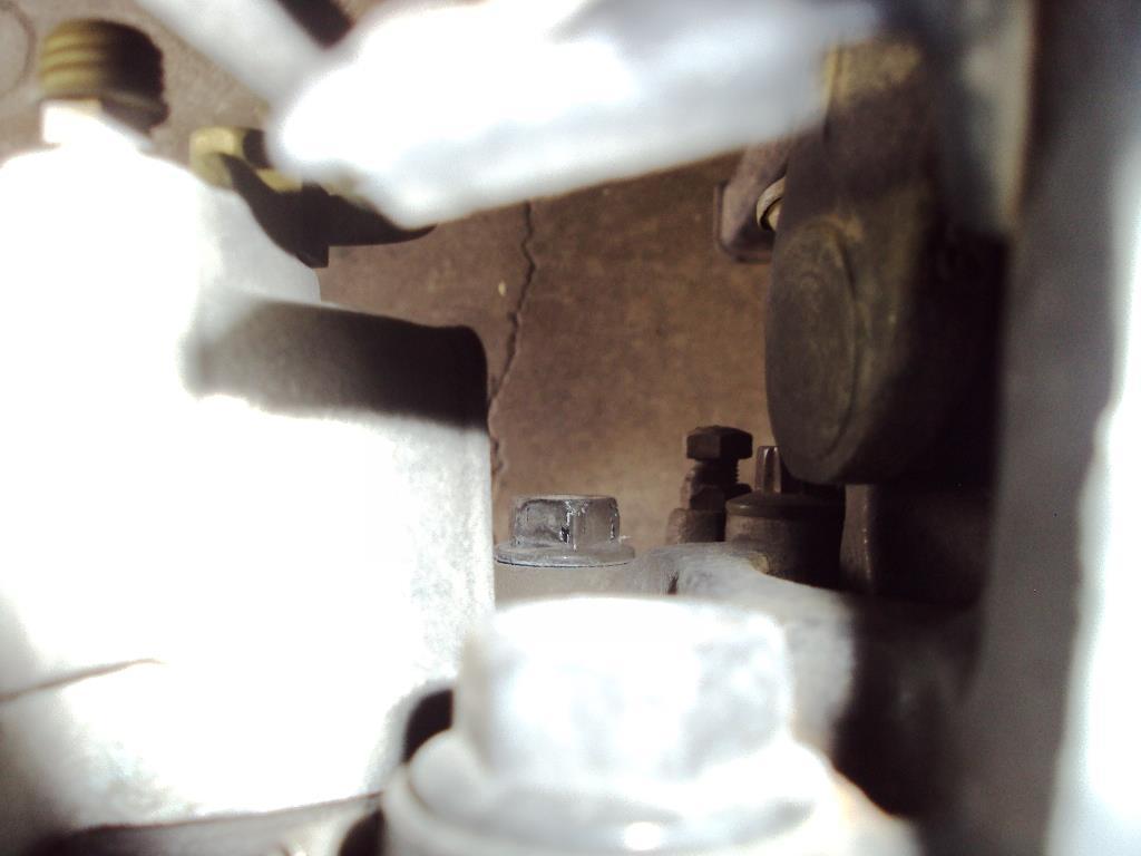
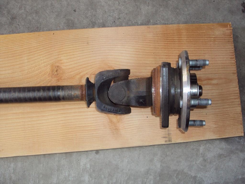
10 , 02:45 AM #2 SilverSport Supporting Member WF Supporting Member Install Synergy Suspension Ball Joints Part 2 10) Pay attention to the plastic guides on the splined end of the axle. There are two of these. If one or both are missing, check inside the axle tube. If they slide off when removing the axle shaft, use a coat hanger or wire rod to fish them out an place them back on the splined end of the axle. Join Date: May 2011 Posts: 22,234 Garage 11) Remove the cotter pin and upper ball joint nut.


11 12) Remove the cotter pin and loosen the lower ball joint nut until only a few threads are left. 13) Give the knuckle several sharp blows with the hammer to break it loose from the ball joints.


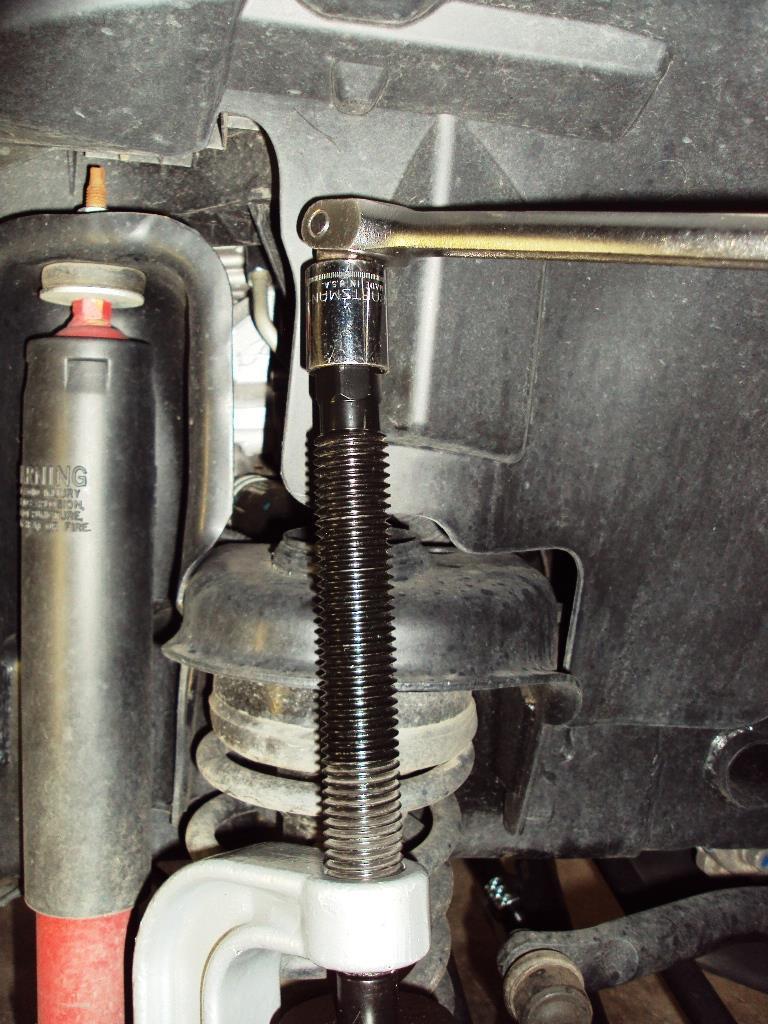
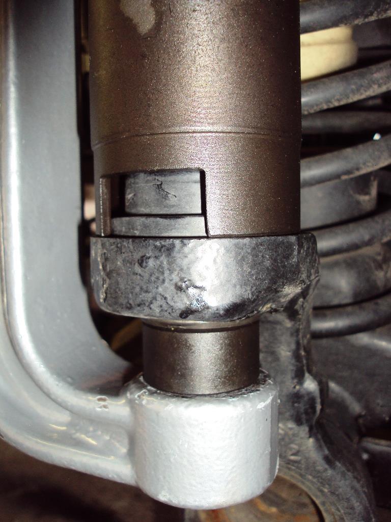
12 14) Remove the lower ball joint nut; then remove the knuckle from the ball joint studs and swing it out of the way. Support the knuckle by placing a jack stand under the tie rod. 15) Using the ball joint press and adapter kit, press the upper ball joint out of the axle 'C'. Tighten the press until the joint comes free. Periodically tap the area of the 'C' around the ball joint with the hammer. The vibrations will help the joint to press out.
13
14
15


16 16) Once the ball joint is loose, remove the press, adapter, and ball joint.
 Turn the press upside down and remove the lower ball joint.")
17 , 02:47 AM #3 SilverSport Supporting Member WF Supporting Member Install Synergy Suspension Ball Joints Part 3 17) Turn the press upside down and remove the lower ball joint. Join Date: May 2011 Posts: 22,234 Garage


18 18) Clean the inside of the ball joint mounting holes with sandpaper or a wire brush and then wipe clean with brake cleaner on a rag. Apply a thin film of anti-seize to the inside of the holes.
 Using sandpaper or a wire brush, clean any rust from the outer 2\" of the axle tube. Wipe clean with brake cleaner on a rag.")
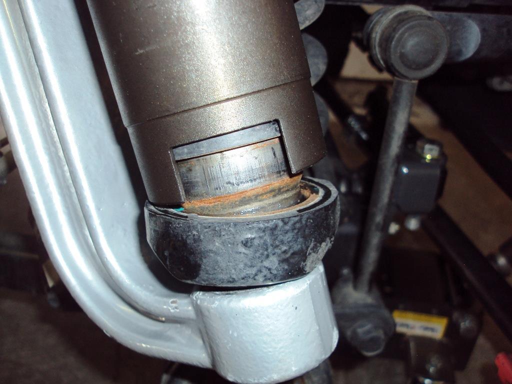
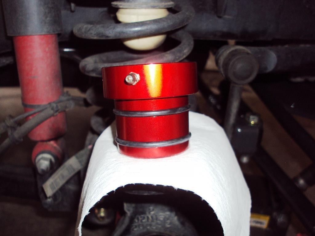
19 19) Clean any dirt and debris from the inside of the axle tube. A vacuum cleaner with an extension wand works well for this. 20) If installing axle tube seals proceed to Step 21. If not, skip to Step ) Using sandpaper or a wire brush, clean any rust from the outer 2" of the axle tube. Wipe clean with brake cleaner on a rag. Apply a thin film of anti-seize to the inside of the axle tube. 22) Turn the axle tube seal so the grease fitting is facing to the rear and push it into the axle tube. If necessary, place a rag over the seal and use a hammer and block of wood to fully seat the seal in the end of the tube.
20


21 23) Remove the boot from the Synergy Suspension lower ball joint by carefully pulling it free.


22 24) Using the press and adapter, install the lower ball joint until the lip is flush against the axle 'C'. MAKE SURE THE HOLE FOR THE GREASE FITTING IS FACING FORWARD AND ANGLED TOWARD THE AXLE 'C'!

23 25) Install the dust boot on the lower ball joint by sliding it up the stud and seating the boot into the groove. Thread the nut onto the stud for safekeeping.


24 26) Install the grease fitting into the ball joint. DO NOT OVERTIGHTEN! 27) Remove the boot from the upper ball joint and install using the press and adapter.


25 28) Install the grease fitting and boot onto upper ball joint. The is very little clearance for the boot to seat inside the axle 'C' so use a small flat blade screwdriver to carefully push it into place.
 Tighten the upper nut to 30 ft lbs. 31) Tighten the lower nut to 85 ft lbs. Then tighten the nut just enough to pass the cotter pin thru the hole.")

26 , 02:48 AM #4 SilverSport Supporting Member WF Supporting Member Install Synergy Suspension Ball Joints Part 4 29) Install the knuckle onto the ball joint studs and start the nuts. 30) Tighten the upper nut to 30 ft lbs. 31) Tighten the lower nut to 85 ft lbs. Then tighten the nut just enough to pass the cotter pin thru the hole. Bend the legs of the cotter pin to secure it in place. Join Date: May 2011 Posts: 22,234 Garage 32) Tighten the upper nut to 75 ft lbs. Then tighten the nut just enough to pass the cotter pin thru the hole. Bend the legs of the cotter pin to secure it in place. 33) Clean the area on the knuckle where the hub bearing mounts with sandpaper or a wire brush. Clean with brake cleaner and a rag and apply a thin film of anti-seize. 34) Clean the area on the hub bearing where it mounts to the knuckle with sandpaper or a wire brush and wipe clean.

27 34A) If you installed axle tube seals, cut the plastic dirt deflector from the axle shaft and clean off the rust. Wipe clean and apply a film of wheel extreme pressure moly grease. Also remove the plastic guides from the inner end of the axle. 35) Place the backing plate on the axle shaft and slide the axle shaft into the axle housing until the hub bearing is 2-3" from the knuckle. 36) Turn the axle so the wheel speed sensor mounting hole is on top. Guide the wheel speed sensor harness under the upper axle 'C' and thru the slot in the backing plate and put carefully put sensor into its' mounting hole. 37) Push the axle shaft fully in so the hub bearing and backing plate are flush against the knuckle. Line up the holes in the knuckle with the holes in the backing plate and hub bearing and install the three 13mm 12 point bolts. Torque the bolts to 70 ft lbs. 38) Clip the wheel speed sensor harness back to the upper ball joint bracket and brake hose. 39) Install the speed sensor mounting screw and tighten to inch pounds. 40) Slide the brake caliper back over the rotor and install the caliper bolts. Tighten to 120 ft lbs. 41) Install wheel/tire and torque the wheel nuts to 95 ft lbs. 42) Remove the jack stand and lower the vehicle. 43) Grease the ball joints until the boots begin to unseat from joints. Re-seat the boots and wipe off the excess grease. 44) Go for a short test drive and make sure the ABS light doesn't come on.
BMW 3 Series E46 Front Wheel Bearing
 BMW 3 Series E46 Front Wheel Bearing Replacement A step-by-step guide on BMW 3 Series E46 Front Wheel Bearing Replacement. Written By: Danielle 2017 guides.drivediy.com Page 1 of 13 INTRODUCTION Discover
2. Rear Axle 4-2 [W2A1] SERVICE PROCEDURE A: REMOVAL 1. DISC BRAKE. Tightening torque: 27.0±2.5 N m (2.75±0.25 kg-m, 19.9±1.
![2. Rear Axle 4-2 [W2A1] SERVICE PROCEDURE A: REMOVAL 1. DISC BRAKE. Tightening torque: 27.0±2.5 N m (2.75±0.25 kg-m, 19.9±1.](/thumbs/93/112592203.jpg "2. Rear Axle 4-2 [W2A1] SERVICE PROCEDURE A: REMOVAL 1. DISC BRAKE. Tightening torque: 27.0±2.5 N m (2.75±0.25 kg-m, 19.9±1.") 4-2 [W2A1] SERVICE PROCEDURE 9) Install tie-rod end ball joint on housing knuckle arm. 27.0±2.5 N m (2.75±0.25 kg-m, 19.9±1.8 (1) Cotter pin (2) Castle nut (3) Tie-rod B4M2214B 10) While depressing brake
4-2 [W2A1] SERVICE PROCEDURE 9) Install tie-rod end ball joint on housing knuckle arm. 27.0±2.5 N m (2.75±0.25 kg-m, 19.9±1.8 (1) Cotter pin (2) Castle nut (3) Tie-rod B4M2214B 10) While depressing brake
SA 8 FRONT AXLE HUB COMPONENTS
 SA8 FRONT AXLE HUB COMPONENTS SA9 REMOVAL OF FRONT AXLE HUB 1. REMOVE COTTER PIN, LOCK NUT CAP AND BEARING LOCK NUT (a) Remove the cotter pin and lock nut cap. (b) Loosen the bearing lock nut while depressing
Installation Instructions
 Preparing your vehicle to install your brake system upgrade 1. Rack the vehicle. 2. If you don t have a rack, then you must take extra safety precautions. 3. Choose a firmly packed and level ground to
3. Front Axle FRONT AXLE. A: REMOVAL 1) Lift-up the vehicle and remove the front wheels. 2) Unlock the axle nut. DS-17
 Lift-up the vehicle and remove the front wheels. 2) Unlock the axle nut. DS-17") FRONT AXLE DRIVE SHAFT SYSTEM 3. Front Axle A: REMOVAL 1) Lift-up the vehicle and remove the front wheels. 2) Unlock the axle nut. 6) Remove the disc rotor from hub. If the disc rotor seizes up within
FRONT AXLE DRIVE SHAFT SYSTEM 3. Front Axle A: REMOVAL 1) Lift-up the vehicle and remove the front wheels. 2) Unlock the axle nut. 6) Remove the disc rotor from hub. If the disc rotor seizes up within
FRONT AXLE HUB SUB-ASSY LH
 3038 DRIVE SHAFT / PROPELLER SHAFT REPLACEMENT HINT: COMPONENTS: SEE PAGE 304 Replace the RH side by the same procedures with LH side. 1. REMOVE FRONT WHEEL 300OI02 2. REMOVE FRONT AXLE HUB LH NUT (a)
1984 Dodge W250 PICKUP
 1984 Dodge W250 PICKUP Submodel: Engine Type: V8 Liters: 5.2 Fuel Delivery: CARB Fuel: GAS Dana 44 MODELS THROUGH 1984 2. Raise and safely support the vehicle, then remove the wheel hub and bearings as
SUSP-09, Rear Wheel Bearing Replacement - Steel Trailing Arm. Acrobat Printable Version
 SUSP-09, Rear Wheel Bearing Replacement - Steel Trailing Arm Introduction Acrobat Printable Version I'd like to thank Ben Davis for providing the pictures for this procedure. Ben took the time to take
Installation Notes: #86000-R Race Series +3.5 L/T Kit
 159 North Maple St. Unit J, CORONA CA 92880 P. 951-737-9682 F. 951-737-9006 WWW.CHAOSFAB.COM Installation Notes: #86000-R Race Series +3.5 L/T Kit Factory manual is recommended for removal and re-installation
INSTALLATION INSTRUCTIONS
 INSTALLATION INSTRUCTIONS 1075 North Ave. Sanger, CA 93657-3539 local: 559-875-0222 fax: 559-876-2259 toll free: 800-445-3767 3100-3200 3 DROPPED FRONT SPINDLE 73-87 1/2 TON C-10 PICK-UP / 1/2 TON BLAZER
FRONT DROP SPINDLES
 92725000 88-98 2 FRONT DROP SPINDLES Thank you for choosing Rough Country for all your suspension needs. Rough Country recommends a certified technician install this system. In addition to these instructions,
RHINO SUSPENSION SYSTEM INSTALLATION INSTRUCTIONS
 PARTS INCLUDED: 2 FRONT UPPER A-ARMS 2 FRONT LOWER A-ARMS 2 UNI-BALL JOINTS 2 UNI-BALL JOINT STUDS 2 UNI-BALL JOINT CAPS 2 RETAINING RINGS 1 FRONT SHOCK ASSEM. 2 DELRON STEERING STOPS 2 SHOCK MOUNT SPACERS
REPLACEMENT 1. REMOVE FRONT WHEEL
 3028 REPLACEMENT 1. REMOVE FRONT WHEEL 300HC03 2. REMOVE FRONT DISC BRAKE CALIPER ASSY LH (a) Remove the bolt and separate the brake tube bracket from the steering knuckle. (b) Using, disconnect the brake
PRE-INSTALLATION Ford F150 4WD 4" Suspension Lift Kit
 2009-2013 Ford F150 4WD 4" Suspension Lift Kit PRE-INSTALLATION 25007 2 - Knuckle (Driv/Pass) 2 - Crossmember (Front/Rear) 2 - Differential Bracket (Driv/Pass) 1 - Diff. Brace Bracket (Pass) 2 - Front
Installation Instructions
 Instructions Created by an: 86-95 Suzuki Samurai Samurai Front Axle Knuckle Rebuild Kits (SKU# SAX-KRK) Installation Instructions Revised 6-6-14 Suggested Tools: CAUTION: Safety glasses should be worn
PRE-INSTALLATION. INSTALLATION INSTRUCTIONS Front Ford F150 4WD 4" Suspension Lift Kit
 2015 Ford F150 4WD 4" Suspension Lift Kit PRE-INSTALLATION 2 - Knuckle (Driv/Pass) 2 - Crossmember (Front/Rear) 2 - Differential Bracket (Driv/Pass) 1 - Diff. Brace Bracket (Pass) 2 - Front Brake Line
DYNATRAC PRODUCTS V5.3
 DYNATRAC PRODUCTS V5.3 2000-2008 Dodge Hub Kit Stage 1 4x4, Front Axle Free Spin Conversion Kit Note: This Kit is not Approved for 2007 & up 3500 Cab and Chassis Trucks Due to a Larger U-Joint (If U-Joint
DESCRIPTION Acura TSX SUSPENSION Front - TSX. NOTE: For system description and component location, see Fig. 1.
 2004 SUSPENSION Front - TSX DESCRIPTION NOTE: For system description and component location, see Fig. 1. Fig. 1: Identifying Front Suspension Components Wednesday, March 12, 2008 8:30:45 8:30:55 PM Page
AEV30308AA Last Updated: 05/31/18. 4 DUALSPORT sc SUSPENSION system for RAM 1500 air ride standard and rebel INSTALLATION GUIDE
 AEV30308AA Last Updated: 05/31/18 4 DUALSPORT sc SUSPENSION system for RAM 1500 air ride standard and rebel INSTALLATION GUIDE PLEASE READ BEFORE YOU START TO GUARANTEE A QUALITY INSTALLATION, WE RECOMMEND
FRONT & 4 REAR GM WD LOWERING KIT
 92725200 88-98 2 FRONT & 4 REAR GM 1500 2WD LOWERING KIT Thank you for choosing Rough Country for all your suspension needs. Rough Country recommends a certified technician install this system. In addition
Replace front brake pads and discs * (Ford Galaxy )
") Replace front brake pads and discs * (Ford Galaxy 2006-2015) *Caution! This instructions are created by random users and must be used as a reference only! Please, take all safety precautions, and if you're
Replace front brake pads and discs * (Ford Galaxy 2006-2015) *Caution! This instructions are created by random users and must be used as a reference only! Please, take all safety precautions, and if you're
INSTALLATION INSTRUCTIONS
 INSTALLATION INSTRUCTIONS --1075 North Ave. Sanger, CA 93657-3539 local: 559-875-0222 fax: 559-876-2259 toll free: 800-445-3767-- 2509 2 DROP SPINDLE 2WD 4WD AWD >>> Must Use 17 Wheels or larger
AXLE SYSTEM PROBLEM SYMPTOMS TABLE AH 1
 AXLE AXLE SYSTEM 1 AXLE SYSTEM PROBLEM SYMPTOMS TABLE HINT: Use the table below to help you find the cause of the problem. The numbers indicate the ranked order of probability of each of the possible causes.
CHEVY C WHEEL DRIVE STANDARD CAB ONLY (EXCEPT 454SS) FTS1588-7BC 4" LIFT SPINDLES
 FTS1588-7BC 4 LIFT SPINDLES") 1988-1991 CHEVY C1500 2 WHEEL DRIVE STANDARD CAB ONLY (EXCEPT 454SS) FTS1588-7BC 4" LIFT SPINDLES PARTS LIST: 1 EA. LIFT SPINDLE PASS. SIDE FT1588-7BCP 1 EA. LIFT SPINDLE DRIVER'S SIDE FT1588-7BCD 6 EA.
1988-1991 CHEVY C1500 2 WHEEL DRIVE STANDARD CAB ONLY (EXCEPT 454SS) FTS1588-7BC 4" LIFT SPINDLES PARTS LIST: 1 EA. LIFT SPINDLE PASS. SIDE FT1588-7BCP 1 EA. LIFT SPINDLE DRIVER'S SIDE FT1588-7BCD 6 EA.
INSTALLATION INSTRUCTIONS
 INSTALLATION INSTRUCTIONS 2102 LOWERING SPINDLE ASSEMBLY 1998-UP CHEVROLET / GMC BLAZER / X-TREME / JIMMY / ENVOY 2 Wheel Drive Congratulations! You were selective enough to choose a BELLTECH PRODUCT.
SUSPENSION - FRONT Toyota Celica DESCRIPTION ADJUSTMENTS & INSPECTION WHEEL ALIGNMENT SPECIFICATIONS & PROCEDURES WHEEL BEARING
 SUSPENSION - FRONT 1988 Toyota Celica FRONT SUSPENSION Toyota DESCRIPTION Vehicles are equipped with front wheel drive and independent MacPherson strut front suspension. Suspension consists of vertically
FRONT DRIVE SHAFT COMPONENTS DS 1 DRIVE SHAFT FRONT DRIVE SHAFT FRONT DRIVE SHAFT HOLE SNAP RING. w/o ABS: AUTOMATIC TRANSMISSION CASE PROTECTOR
 FRONT DRIVE SHAFT DRIVE LINE SHAFT COMPONENTS 1 FRONT DRIVE SHAFT HOLE SNAP RING 23 (235, 17) FRONT DRIVE SHAFT ASSEMBLY RH w/o ABS: AUTOMATIC TRANSMISSION CASE PROTECTOR FRONT DRIVE SHAFT ASSEMBLY LH
Commander SUSPENSION SYSTEM INSTALLATION INSTRUCTIONS
 PARTS INCLUDED: 2 - FRONT UPPER A-ARMS 2 - FRONT LOWER A-ARMS 4 - COTTER PINS 2-12MM JAM NUTS 2 - TIE ROD EXTENDERS 8- FLANGED DELRON BUSHINGS 4- DELRON CASTER SPACERS 6 - GREASE FITTINGS 3 - BEARING REMOVAL
components is critical so that the splines are not damaged. NOTE: Never force the hub unit bearing assembly onto the shaft or strike with a hammer.
 Automotive TechTips Volume 6 Issue 4 Part 3 of a 3-Part Series Installing a Hub Unit Bearing Assembly and Steering Knuckle Guidelines for Timken continues to lead the hub unit bearing evolution by providing
1988 Jeep Truck Wrangler L L VIN H TBI Copyright 2013, ALLDATA 10.52SS Page 1 Technical Service Bulletin # Date:
 1988 Jeep Truck Wrangler L4-150 2.5L VIN H TBI Copyright 2013, ALLDATA 10.52SS Page 1 Technical Service Bulletin # 025288 Date: 880711 Right Front Axle Shaft Seal - Installation Models 1986-88 Jeep Comanche,
WARNING: Only perform this installation if you are experienced, fully equipped mechanic.
 DYNATRAC V3.2 2005-Present Ford Super Duty 250/350-4x4, Front Axle, Free Spin Conversion Kit Some of the less common tools, which will be required: 6 point Spanner socket (OTC #7090-A or equivalent). These
Powerslot Mustang Rotors (Rear Pair GT/V6) - Installation Instructions
 - Installation Instructions") Powerslot Mustang Rotors (Rear Pair 94-04 GT/V6) - Installation Instructions The below installation instructions work for the following products: Powerslot Mustang Rotors (Rear Pair 94-04 GT/V6) Please
Powerslot Mustang Rotors (Rear Pair 94-04 GT/V6) - Installation Instructions The below installation instructions work for the following products: Powerslot Mustang Rotors (Rear Pair 94-04 GT/V6) Please
INSTALLATION INSTRUCTIONS
 INSTALLATION INSTRUCTIONS 2100 DROPPED FRONT SPINDLE CHEVROLET 2WD S-10 / S-15 PICKUP / BLAZER / JIMMY, including models with ABS General Motors G-Body Rear Wheel Drive Cars CONGRATULATIONS! You were selective
Full Tilt Boogie (FTBR) Subframe Bushing Kit Install (99-04 Cobra)
 Subframe Bushing Kit Install (99-04 Cobra)") Full Tilt Boogie (FTBR) Subframe Bushing Kit Install (99-04 Cobra) Tools Required: Jack and jack stands (Or a lift) Metric sockets 8,12,15,18,21mm and a 12pt 12mm socket for driveshaft bolts T40 torx bit
Full Tilt Boogie (FTBR) Subframe Bushing Kit Install (99-04 Cobra) Tools Required: Jack and jack stands (Or a lift) Metric sockets 8,12,15,18,21mm and a 12pt 12mm socket for driveshaft bolts T40 torx bit
Wheel Bearing and Wheel Hub All-Wheel Drive (AWD) Vehicles
 Vehicles") Rear Suspension Wheel Bearing and Wheel Hub All-Wheel Drive (AWD) Vehicles All-Wheel Drive (AWD) Vehicles Front Wheel Drive (FWD) Vehicles Removal All vehicles NOTICE: Suspension fasteners are critical
Rear Suspension Wheel Bearing and Wheel Hub All-Wheel Drive (AWD) Vehicles All-Wheel Drive (AWD) Vehicles Front Wheel Drive (FWD) Vehicles Removal All vehicles NOTICE: Suspension fasteners are critical
03-04 Mach 1. Hellion Power Systems Mach 1 Kit Instructions
 Hellion Power Systems 03-04 Mach 1 Kit Instructions Part 1 Hellion recommends that the front suspension system be installed either by trained professionals or by 5.Remove rack bolts K-Member Installation
The following information shows the steps to change the rear brake pads and rotors on an E36 chassis.
 1 of 20 1/18/2010 9:15 PM See More DIY Articles Bookmark Site! The following information shows the steps to change the rear brake pads and rotors on an E36 chassis. Disclaimer: The following information
ALLDATA Online Lexus LS 400 V8-4.0L (1UZ-FE) - Front. Front
 - Front. Front") Page 1 of 18 Home Account Contact ALLDATA Log Out Help PAUL REDEHOFT Select Vehicle New TSBs Technician's Reference Component Search: OK 1991 Lexus LS 400 V8-4.0L (1UZ-FE) Conversion Calculator Vehicle
Page 1 of 18 Home Account Contact ALLDATA Log Out Help PAUL REDEHOFT Select Vehicle New TSBs Technician's Reference Component Search: OK 1991 Lexus LS 400 V8-4.0L (1UZ-FE) Conversion Calculator Vehicle
kit contents trail-safe samurai inner axle seal suzuki samurai (all engines) InstalLation Instructions
 InstalLation Instructions") InstalLation Instructions trail-safe samurai inner axle seal 300748-3-kit 1986-1995 suzuki samurai (all engines) kit contents 5356 PINE AVE FRESNO, CA 93727 USA TOLL FREE: 877.4X4.TOYS WORLDWIDE: 559.252.4950
InstalLation Instructions trail-safe samurai inner axle seal 300748-3-kit 1986-1995 suzuki samurai (all engines) kit contents 5356 PINE AVE FRESNO, CA 93727 USA TOLL FREE: 877.4X4.TOYS WORLDWIDE: 559.252.4950
Max IV Rear Axle Replacement For models after Serial Number and all rear splined axle replacements.
 Max IV Rear Axle Replacement For models after Serial Number 19089 and all rear splined axle replacements. 10/8/03 Max IV Snap Ring Rear Axle replacement.doc Tools required: 9/16 Wrench 6 Extension Steel
Next, chase the threads in the lower A-arm mounts with the 5/8-18 tap and blowout any remaining particles.
 Next, chase the threads in the lower A-arm mounts with the 5/8-18 tap and blowout any remaining particles. Now, apply some anti-seize to the threads of the pivot stud. Also put anti-seize inside the bore
1990 SUSPENSION Front ES250, LS400
 SUSPENSION - FRONT Article Text 1990 Lexus LS 400 For Lextreme Copyright 1998 Mitchell Repair Information Company, LLC Thursday, January 29, 2004 04:56PM ARTICLE BEGINNING 1990 SUSPENSION Front ES250,
PPM-D44538RJK JK Rear 5.38 Ring and Pinion Installation Instructions Version 1
 PPM-D44538RJK JK Rear 5.38 Ring and Pinion Installation Instructions Version 1 GENERAL NOTES: Gear set up and installation should be performed by someone experienced in gear and axle set up Special tools
1999 Toyota RAV DRIVE AXLES AWD & FWD Axle Shafts - RAV4 & RWD Axle Shafts - MR2. AWD & FWD Axle Shafts - RAV4 & RWD Axle Shafts - MR2
 1999-2000 DRIVE AXLES AWD & FWD Axle Shafts - RAV4 & RWD Axle Shafts - MR2 DESCRIPTION & OPERATION On RAV4 models, axle shafts transfer power from transaxle to front wheels (FWD), or front and rear wheels
INSTALLATION INSTRUCTIONS
 INSTALLATION INSTRUCTIONS 2500 DROPPED FRONT SPINDLE CHEVROLET C / K and G.M.C. SIERRA 1500 / 2500 / 3500 Pick-Ups Congratulations! You were selective enough to choose a BELLTECH PRODUCT. We have spent
4. Rear Axle REAR AXLE
 REAR AXLE DRIVE SHAFT SYSTEM 4. Rear Axle A: REMOVAL 1) Disconnect the ground cable from battery. 2) Lift-up the vehicle, and remove the rear wheel. 3) Unlock the axle nut. 4) Remove the axle nut using
JOINT SHAFT REMOVAL/INSTALLATION
 2001 MPV 2001 - MPV - Workshop Manual - Driveline/Axle JOINT SHAFT REMOVAL/INSTALLATION Report a problem with this article Performing the following procedures without first removing the ABS wheel speed
See SPECIFICATIONS & PROCEDURES article in WHEEL ALIGNMENT. Lower Ball Joint 1-22 ( ) Upper Ball Joint 6-39 ( )
 Upper Ball Joint 6-39 ( )") Page 1 of 9 ARTICLE BEGINNING DESCRIPTION Front suspension uses coil springs with integral shock absorbers. Coil springs are mounted between the upper control arms and vehicle frame. A stabilizer bar controls
Page 1 of 9 ARTICLE BEGINNING DESCRIPTION Front suspension uses coil springs with integral shock absorbers. Coil springs are mounted between the upper control arms and vehicle frame. A stabilizer bar controls
Steeda Bumpsteer Kit (94-04) - Installation Instructions
 - Installation Instructions") Steeda Bumpsteer Kit (94-04) - Installation Instructions The below installation instructions work for the following products: Steeda Bumpsteer Kit (94-04) Please read through the instructions carefully
Steeda Bumpsteer Kit (94-04) - Installation Instructions The below installation instructions work for the following products: Steeda Bumpsteer Kit (94-04) Please read through the instructions carefully
WRANGLER, CHEROKEE AND COMANCHE, FRONT AXLE WHEEL HUB CONVERSION KIT
 WRANGLER, CHEROKEE AND COMANCHE, FRONT AXLE WHEEL HUB CONVERSION KIT -YA WU-07 5 x 4.5 -YA WU-08 5 x 5.5 *THIS KIT IS NOT INTENDED FOR VEHICLES WITH ABS AND YA WU-08 WILL CHANGE BOLT PATTERN TO 5 ON 5.5*
Next, set the bar level and tighten it down. Do this on both the driver and passenger sides.
 Next, set the bar level and tighten it down. Do this on both the driver and passenger sides. Using two tape measures, measure the outside width at the front and the rear of the tubes. The front dimension
Constant Velocity Joint: Service and Repair Wheel Drive Shaft Outer Joint and Boot Replacement REMOVAL PROCEDURE
 Constant Velocity Joint: Service and Repair Wheel Drive Shaft Outer Joint and Boot Replacement REMOVAL PROCEDURE Tools Required - J 8059 Snap Ring Pliers - J 35910 Seal Clamp Tool - J 41048 Small Swage
PRE-INSTALLATION. INSTALLATION INSTRUCTIONS Front Dodge Ram WD 6" Suspension Lift Kit
 2012-2015 Dodge Ram 1500 4WD 6" Suspension Lift Kit PRE-INSTALLATION 35015 2 - Knuckle (Driv/Pass) 2 - Crossmember (Front/Rear) 2 - Differential Bracket (Driv/Pass) 1 - Diff. Brace Bracket (Pass) 2 - Front
Slide the billet aluminum cap over the bushing and secure with the 3/8-16 x 2 1/2 socket head allen and locknuts provided.
 Slide the billet aluminum cap over the bushing and secure with the 3/8-16 x 2 1/2 socket head allen and locknuts provided. Put the urethane bushings into the upper antiroll-bar-link eyebolt. Coat the bushings
Audi B5 A4/S4 Rear Wheel Bearing Service Kit
 Audi B5 A4/S4 Installation Tutorial ES2561175 This tutorial is provided as a courtesy by ECS Tuning. Proper service and repair procedures are vital to the safe, reliable operation of all motor vehicles
TOYOTA FJ CRUISER 6 SUSPENSION KIT
 92177000 TOYOTA FJ CRUISER 6 SUSPENSION KIT Thank you for choosing Rough Country for your suspension needs. Rough Country recommends a certified technician installs this system. In addition to these instructions,
DRIVE SHAFT LOCATION INDEX
 DRIVE SHAFT LOCATION INDEX 2005 DRIVELINE/AXLE Drive Shaft - MX-5 Miata Fig. 1: Identifying Drive Shaft Location DRIVE SHAFT PRE-INSPECTION 1. Inspect the dust boot on the drive shaft for cracks, damage,
Front Hub and Disc (4WD Model)
") 4C 8 DRIVE SHAFT SYSTEM Disassembled View Front Hub and Disc (4WD Model) 411RW001 Legend (1) Bolt (2) Cap (3) Snap Ring and Shim (4) Hub Flange (5) Lock Washer and Lock Screw (6) Hub Nut (7) Outer Bearing
4C 8 DRIVE SHAFT SYSTEM Disassembled View Front Hub and Disc (4WD Model) 411RW001 Legend (1) Bolt (2) Cap (3) Snap Ring and Shim (4) Hub Flange (5) Lock Washer and Lock Screw (6) Hub Nut (7) Outer Bearing
E31 Repair Procedure Replace Front Wheel Hub/Bearing Assembly
 E31 Repair Procedure 31-21 Replace Front Wheel Hub/Bearing Assembly Disclaimer This repair procedure is provided as is and is not authoritative with respect to any BMW repair operation. Mark F. Fling is
 Page 1 of 9 FRONT AXLE HUB & WHEEL BEARING Removal (Avalon, Camry, Camry Solara & Sienna) 1. 2. 3. 4. 5. 6. 7. 8. Remove front wheel. Check wheel bearing backlash and deviation (rotational free play).
Audi B6/B7 A4/S4 Rear Wheel Bearing Service Kit
 Audi B6/B7 A4/S4 Installation Tutorial ES2561175 This tutorial is provided as a courtesy by ECS Tuning. Proper service and repair procedures are vital to the safe, reliable operation of all motor vehicles
ALLOY USA AXLE INSTALLATION (99-04 GT, Mach 1)
") ALLOY USA AXLE INSTALLATION (99-04 GT, Mach 1) Time Necessary: Approximately 4 hours Tools Required: Wrenches: 8mm, 13mm, 15mm, 5.5 mm allen, 6mm allen Sockets: 5/8, 3/4 Ratchet Floor Jack Jack Stands
ALLOY USA AXLE INSTALLATION (99-04 GT, Mach 1) Time Necessary: Approximately 4 hours Tools Required: Wrenches: 8mm, 13mm, 15mm, 5.5 mm allen, 6mm allen Sockets: 5/8, 3/4 Ratchet Floor Jack Jack Stands
First, check and record the camber and caster readings, they will be adjusted later.
 First, check and record the camber and caster readings, they will be adjusted later. The caliper-mounting bosses are machined perpendicular to the spindle so they are an excellent place for the level.
BBK LONG TUBE HEADERS (99-04 GT, Mach 1, Bullitt)
") BBK LONG TUBE HEADERS (99-04 GT, Mach 1, Bullitt) Install Time: Approx. 8-10 hrs Parts Needed: BBK Long Tube Headers Shorty mid pipe X/H O2 wiring harness extensions Hi-temp thread locker Tools Required:
BBK LONG TUBE HEADERS (99-04 GT, Mach 1, Bullitt) Install Time: Approx. 8-10 hrs Parts Needed: BBK Long Tube Headers Shorty mid pipe X/H O2 wiring harness extensions Hi-temp thread locker Tools Required:
Changing the Struts on a WK Jeep CRD
 Changing the Struts on a WK Jeep CRD Step by Step By Chirpz Disclaimer: I do not claim that this procedure is the right way or even the best way to change your struts. This is what I did after reading
DYNATRAC V6.0. WARNING: Only perform this installation if you are experienced, fully equipped mechanic.
 DYNATRAC V6.0 1999-2004 Ford Super Duty 250/550-4x4, Front Axle, Free Spin Conversion Kit Some of the less common tools, which will be required: 6 point Spanner socket (OTC #7090-A or equivalent) OR 4
OVERVIEW: KIT INCLUDES:
 Please visit www.fordracingparts.com for the most current instruction information!!! PLEASE READ ALL OF THE FOLLOWING INSTRUCTIONS CAREFULLY PRIOR TO INSTALLATION. AT ANY TIME YOU DO NOT UNDERSTAND THE
TOYOTA TUNDRA BIG BRAKE KIT Section I - Installation Preparation
 TOYOTA TUNDRA 2007- BIG BRAKE KIT Section I - Installation Preparation Part Number: PTR09-34070 Kit Contents Item # Quantity Reqd. Description 1 1 Brake Rotor, LH Front 2 1 Brake Rotor, RH Front 3 1 Brake
for Audi B6 A4/S4 Installation Procedures Front Wheel Bearing Replacement This tutorial is provided as a courtesy by ECS Tuning.
 Installation Procedures Front Wheel Bearing eplacement for This tutorial is provided as a courtesy by ECS Tuning. Proper service and repair procedures are vital to the safe, reliable operation of all motor
09-UP FORD F150 6 LIFT KIT
 92159800 09-UP FORD F150 6 LIFT KIT THANK YOU FOR CHOOSING ROUGH COUNTRY FOR YOUR SUSPENSION NEEDS. Rough Country recommends a certified technician install this system. In addition to these instructions,
2010 Jeep Truck Compass 4WD L4-2.4L
 1 of 8 3/18/2013 5:21 PM 2010 Jeep Truck Compass 4WD L4-2.4L Vehicle» Transmission and Drivetrain» Drive Axles, Bearings and Joints» Axle Shaft Assembly» Service and Repair» Half Shaft - Removal» Front
1998 Plymouth Breeze SUSPENSION' 'Rear - Cirrus, Stratus, Breeze & Sebring Convertible SUSPENSION
 DESCRIPTION 1998-99 SUSPENSION Rear - Cirrus, Stratus, Breeze & Sebring Convertible Rear suspension uses a short/long arm independent design. See Fig. 1. Each side consists of a strut assembly, upper control
Installation Guide: Front Brake Pad
 Installation Guide: Front Brake Pad Ninety percent of the brake pad changes you make during the life of your vehicle will be to the front brakes because they do 60% to 70% of the braking. On most cars,
INSTALLATION INSTRUCTIONS 88518
 INSTALLATION INSTRUCTIONS 88518 For Rancho Suspension Systems RS6518: 2009 FORD F-150 4WD READ ALL INSTRUCTIONS THOROUGHLY FROM START TO FINISH BEFORE BEGINNING INSTALLATION Rev A IMPORTANT NOTES! WARNING:
InstalL Instructions. trail-creeper 4.70 transfer case gear kit ( KIT and KIT) kit contents
 kit contents") InstalL Instructions trail-creeper 4.70 transfer case gear kit (105000-1-KIT and 105001-1-KIT) kit contents 5356 PINE AVE FRESNO, CA 93727 USA TOLL FREE: 877.4X4.TOYS WORLDWIDE: 559.252.4950 WWW.TRAIL-GEAR.COM
InstalL Instructions trail-creeper 4.70 transfer case gear kit (105000-1-KIT and 105001-1-KIT) kit contents 5356 PINE AVE FRESNO, CA 93727 USA TOLL FREE: 877.4X4.TOYS WORLDWIDE: 559.252.4950 WWW.TRAIL-GEAR.COM
Hawk HP Performance Brake Pads (94-98 GT/V6 Front Pair) - Installation Instructions
 - Installation Instructions") Hawk HP Performance Brake Pads (94-98 GT/V6 Front Pair) - Installation Instructions The below installation instructions work for the following products: Hawk HP Plus Performance Brake Pads (94-98 GT/V6
Hawk HP Performance Brake Pads (94-98 GT/V6 Front Pair) - Installation Instructions The below installation instructions work for the following products: Hawk HP Plus Performance Brake Pads (94-98 GT/V6
SUSPENSION. Front - Corvette
 1998-99 SUSPENSION Front - Corvette DESCRIPTION The major suspension components are made of high-strength, lightweight, forged aluminum alloy. A fiberglass single-leaf spring is mounted transversely below
4. SEPARATE SPEED SENSOR FRONT LH (a) Remove the bolt and disconnect the speed sensor wire and flexible hose from the shock absorber assy.
 Remove the bolt and disconnect the speed sensor wire and flexible hose from the shock absorber assy.") OVERHAUL Refer to components: See page 304 Use the same procedures for the RH side and LH side. The procedures listed below are for the LH side. 1. DRAIN TRANSAXLE OIL (a) Using a #10 socket hexagon wrench,
OVERHAUL Refer to components: See page 304 Use the same procedures for the RH side and LH side. The procedures listed below are for the LH side. 1. DRAIN TRANSAXLE OIL (a) Using a #10 socket hexagon wrench,
04-08 FORD F150 4 KIT
 9257700 04-08 FORD F50 4 KIT THANK YOU FOR CHOOSING ROUGH COUNTRY FOR YOUR SUSPENSION NEEDS. Rough Country recommends a certified technician install this system. In addition to these instructions, professional
*1553BAG3* F-150 2WD 4 /5 /6 LIFT KIT 1553BAG3
 *1553BAG3* 1553BAG3 921553220 2015-16 F-150 2WD 4 /5 /6 LIFT KIT THANK YOU FOR CHOOSING ROUGH COUNTRY FOR YOUR SUSPENSION NEEDS. Rough Country recommends a certified technician install this system. In
Slave Cylinder Weep Hole Drilling Procedure
 Slave Cylinder Weep Hole Drilling Procedure Tools Required: T20 Torx Driver T25 Torx Driver T25 Torx Bit with ¼ Ratchet Wrench 4mm Hex Key (Allen wrench) 5mm Hex Key 6mm Hex Key 8mm Hex Key 12mm Hex Key
Exhaust System and Catalytic Converter Dis-Assembly
 Installation Guidelines For Audi-VW ZF 5-Speed Automatic Transmission Output Flange Seal! CAUTION! Performing work on your automobile without having proper knowledge, mechanical ability or the proper tools
Fig. 1: Exploded view of the 2WD hub and bearings
 Page 1 of 8 Front Wheel Bearings REPLACEMENT NOTE: Sodium-based grease is not compatible with lithium-based grease. Read the package labels and be careful not to mix the two types. If there is any doubt
»Product» Safety Warning
 #F2402 & F2602 Installation Instructions 2004-2008 Ford F-150 4wd 4-6" Lift System Read and understand all instructions and warnings prior to installation of product and operation of vehicle. Zone Offroad
Installation Instructions COMPETITION/PLUS SHIFTER Ford Mustang MT82 6-Speed Manual Transmission Catalog#
 Installation Instructions COMPETITION/PLUS SHIFTER 2015-2017 Ford Mustang MT82 6-Speed Manual Transmission Catalog# 3916037 Rev. 00 WORK SAFELY! For maximum safety, perform this installation on a clean,
Constant velocity joints, inner
 "VCC001037 EN 20120826" 1(2) Constant velocity joints, inner Special tools: 951 2619 Note! For removing drive shafts Removing drive shafts. The method is the same for the left and right drive shaft. Expose
04-08 FORD F150 6 KIT
 957600 THANK YOU FOR CHOOSING ROUGH COUNTRY FOR YOUR SUSPENSION NEEDS. 0-08 FORD F50 6 KIT Rough Country recommends a certified technician install this system. In addition to these instructions, professional
FRONT SUSPENSION LOCATION INDEX
 1. Remove the front suspension tower bar. (See FRONT SUSPENSION TOWER BAR REMOVAL/INSTALLATION.) 2007 Mazda MX-5 Miata Sport 2007 SUSPENSION Front Suspension - MX-5 Miata FRONT SUSPENSION LOCATION INDEX
*1576BAG9* 1576BAG FORD F KIT C THANK YOU FOR CHOOSING ROUGH COUNTRY FOR YOUR SUSPENSION NEEDS.
 957600C THANK YOU FOR CHOOSING ROUGH COUNTRY FOR YOUR SUSPENSION NEEDS. 0-08 FORD F50-6 KIT Rough Country recommends a certified technician install this system. In addition to these instructions, professional
JK 8 Lug Front Locking Hub Conversion Kit
 JK 8 Lug Front Locking Hub Conversion Kit Kit #3034411 w/ Performance Rotors Kit #3034410 w/ Performance Slotted Rotors Kit #3034412 w/ Big Brake Kit Kit #3034413 w/ Big Brake Kit and Slotted Rotors Important
INSTALLATION INSTRUCTION 88088
 INSTALLATION INSTRUCTION 88088 For Rancho Suspension Systems RS6588 & RS6589: FORD F-150 READ ALL INSTRUCTIONS THOROUGHLY FROM START TO FINISH BEFORE BEGINNING INSTALLATION Rev B IMPORTANT NOTES! WARNING:
CAUTION: Use a rag at the point you are going to pry. because aluminum alloy wheels can be easily damaged.
 Front Suspension Knuckle/Hub Replacement NOTE: Use only genuine Honda aluminum wheel weights. Non-genuine aluminum wheel weights may corrode and damage aluminum wheels. Remove the center cap by prying
REAR DRIVE SHAFT (3S GTE ENGINE)
") SA52 REAR DRIVE SHAFT (3SGTE ENGINE) COMPONENTS SA53 NOTICE: The axle bearing could be damaged if it is subjected to the vehicle weight, such as when moving the vehicle with the drive shaft removed. Therefore,
SA52 REAR DRIVE SHAFT (3SGTE ENGINE) COMPONENTS SA53 NOTICE: The axle bearing could be damaged if it is subjected to the vehicle weight, such as when moving the vehicle with the drive shaft removed. Therefore,
1. General Description
 General Description 1. General Description A: SPECIFICATION 1. PROPELLER SHAFT Propeller shaft type 3UJ Front propeller shaft Joint-to-joint length: L 1 mm (in) 633 (24.92) Rear propeller shaft Joint-to-Joint
INSTALLATION INSTRUCTION 88148
 INSTALLATION INSTRUCTION 88148 Rev C For Rancho Suspension Systems RS6548, RS6549 & RS6550: GM 2500HD, 2500, and 1500HD Trucks READ ALL INSTRUCTIONS THOROUGHLY FROM START TO FINISH BEFORE BEGINNING INSTALLATION
TABLE OF CONTENTS 0 FRONT DRIVE , WHEEL HUB , WHEEL HUB BEARING , KNUCKLE
 Subsection 01 (TABLE OF CONTENTS) TABLE OF CONTENTS 0 FRONT DRIVE... 06-02-1 1, WHEEL HUB... 06-02-2 2, WHEEL HUB BEARING... 06-02-2, KNUCKLE... 06-02- FINAL DRIVE... 06-0-1 1, DRIVE CHAIN... 06-0-2 2,
INSTALLATION INSTRUCTIONS
 INSTALLATION INSTRUCTIONS --1075 North Ave. Sanger, CA 93657-3539 local: 559-875-0222 fax: 559-876-2259 toll free: 800-445-3767-- 2511 2 DROP SPINDLE 2WD (Must Use 17 or larger wheels AND be used for 3+
How to install Front Brake Pads on your GT, V6
 Time Necessary: Approximately 1.5 hours Tools Required: How to install Front Brake Pads on your 99-04 GT, V6 Jack Jack stands Torque wrench Ratchet Lug wrench 15mm socket 12mm socket Large C-clamp Syringe
SCION tc BIG BRAKE KIT Section I - Installation Preparation
 SCION tc 2005- BIG BRAKE KIT Section I - Installation Preparation Part Number: PTR09-21080 Kit Contents Item # Quantity Reqd. Description 1 1 Brake Rotor, LH Front 2 1 Brake Rotor, RH Front 3 1 Brake Caliper
Installation Instructions 7 Lift Kit 2015 F150 4WD ONLY( )
") IF YOUR ReadyLIFT OFF ROAD SUSPENSION PRODUCT IS MISSING A PART OR HAS A DAMAGED PART, PLEASE CONTACT CUSTOMER SERVICE DIRECTLY. A NEW REPLACEMENT PART WILL BE SENT TO YOU IMMEDIATELY Please read Instructions
IF YOUR ReadyLIFT OFF ROAD SUSPENSION PRODUCT IS MISSING A PART OR HAS A DAMAGED PART, PLEASE CONTACT CUSTOMER SERVICE DIRECTLY. A NEW REPLACEMENT PART WILL BE SENT TO YOU IMMEDIATELY Please read Instructions