Installation and Maintenance. Helical and Bevel Helical Gear Units KUMERA POWER TRANSMISSION GROUP
|
|
|
- Sherilyn Greer
- 5 years ago
- Views:
Transcription


1 Installation and Maintenance Helical and Bevel Helical Gear Units KUMERA POWER TRANSMISSION GROUP
2 2/37 Gear unit installation and maintenance A


 48 54 54 Fax +47 (33) 48 54 55 Email sales@kumera.")
3 Kumera Drives Oy Headquarters Kumerankatu 2 FI RIIHIMÄKI Finland Tel Fax drives@kumera.com service@kumera.com 24h service Kumera Antriebstechnik GmbH Mr. B. Reisinger Raiffeisenstrasse A-8010 GRAZ Austria Tel. +43 (316) Fax +43 (316) kumera.graz@kumera.com Kumera A/S Mr. Richard Horntvedt P.O.Box 2043 N-3202 SANDEFJORD Norway Tel. +47 (33) Fax +47 (33) sales@kumera.no Kumera Shanghai Rep. Office Mr. Fang Cheng Qu Room 715, Fortune Times 1438 North Shanxi Road SHANGHAI China Tel Fax kumerachina@kumera.com 3/37
4 Introduction These are general instructions for persons installing, operating or maintaining helical and bevel helical gear units made by Kumera Drives Oy. They should read and understand the contents of these instructions. Kumera Drives Oy is not liable for any damages caused by not following these instructions. Symbols To be observed during operation and maintenance. Important issue to be observed during installation, operation and maintenance. The gear units described in the instructions are similar to the gear units being manufactured at time of writing. Copyright: These instructions are Kumera Drives Oy. The instructions must not be used for commercial or competitive purposes without the permission of Kumera Drives Oy. 4/37
5 Contents 1 Safety Gear noise pressure levels Screw tightening torques Technical Information Type plate Type code Storage Normal protection Long-term protection Installation and Start-up Gear unit start-up Installing of a foot-mounted gear unit Lifting Mounting a coupling Installing of a shaft-mounted gear unit with a keyway Installing of a shaft-mounted gear unit with a shrink disc Installing a torque arm Installing of a motor to the gear unit Installing of a V-belt drive Installing of a tooth-belt drive Installing of a chain drive Filling lubrication oil Installing of the breather plug Lubrication Lubrication basics Oil and grease quantities Oil change Cleanliness of oil Oil preheating Oil cooling Synthetic lubricants Breather plug Recommended lubricants Gear Unit Design Housing Toothed parts Bearings Sealing Gear Unit Accessories Backstop Lubrication pumps Pressure lubrication unit Gear unit cooling methods Heating the gear unit oil Vibration measurement adapter Temperature sensor PT Scheduled Maintenance Troubleshooting /37
6 1 Safety In order to prevent any damages, transportation, unpacking, installation and setup shall be performed by professional personnel in accordance with the instructions of Kumera Drives Oy. A gear unit must not be installed in a place or used in a way it was not designed for. Gear units are delivered to the customer in accordance with the information supplied to Kumera Drives Oy, and this information must not be deviated from when installing the gear unit. Gear units must not be subjected to extra application of load due to installation. Consider safe operation when installing the gear unit. Protect places dangerous to the operator. Do not make any changes to the structure and guards of our gear units. Kumera Drives Oy is not liable for structural changes or changes to the guards made by another party. Do not remove the safety devices while the gear unit is in use. Perform any maintenance operations while the gear unit is standing still. When opening inspection covers, make sure that no foreign objects or impurities can enter the gear unit. may generate noise pressure levels in excess of the permissible noise pressure level, depending on the output power level of the gear unit. Persons working near the gear unit must use the appropriate protection. The gear units may warm up to the extent that their surface becomes hot. Avoid touching the gear surface during operation. The gear unit was packed at the Kumera Drives Oy factory according to the terms of delivery, in such a way that it withstands normal transportation. When lifting the gear unit, use its lifting eyes. See the machine plate for the weight of the gear. The gear lifting eyes are only for lifting the gear unit, not for accessories such as an electric motor. Do not use the shafts when lifting. Report any damage during transport to Kumera Drives Oy immediately. 6/37
7 1.1 Gear noise pressure levels Table 1 lists the noise level behaviour of helical and bevel helical gear units in accordance with the power class of the gear. The table values are calculated and indicative, and they can be used for comparison with the noise level of the gear unit during operation. According to the ISO 4871 standard, the emission sound pressure level is to be measured at a distance of 1 metre from the outer surface of the gear unit. Noise level variations due to accessories are not taken into account in the table. One fan increases the noise level by approx. 3 db(a). Major deviations from the values must be examined in order to establish the cause of the unusually loud noise. TABLE 1. Output power / emission sound pressure levels of helical and bevel helical gear units. Helical gear units Bevel helical gear units Unit output (kw) Noise level (dba) Unit output (kw) Noise level (dba) /37
8 1.2 Screw tightening torques All the screw connections mentioned in the instructions must be tightened according to Table 2, unless otherwise mentioned in the installation instruction. We recommend to grease the screws before installation. The table provides values for dry and greased (friction coefficient 0.10) screws. TABLE 2. Screw tightening torques. Thread size Dry (Nm) Grade 8.8 Grade 10.9 Grade 12.9 Greased (Nm) Dry (Nm) Greased (Nm) Dry (Nm) Greased (Nm) M M M M M M M /37
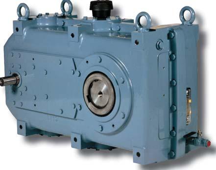
9 2 Technical Information 2.1 Type plate A type plate is installed during packing onto all the gear units supplied by us. The plate contains the required identification information and lubrication recommendations of the gear unit. KUMERA FINLAND Type KFBM-3180 H1J LBS 4 E1 i 56/1 308 kg EP Oil ISO VG ,6 L AGMA 5EP No. D311124/ / 1 Type: Gear unit type (see page 10) i: Nominal gear ratio kg: Weight without oil EP Oil: Recommended viscosity of lubrication oil L: Indicative oil capacity, to be checked using the oil sight glass or dipstick No. : Gear unit serial number 9/37
10 2.2 Type code 10/37
11 3 Storage 3.1 Normal protection The gear units have been treated as follows before delivery: The internal parts of the gear unit are protected by oil that spreads to their surfaces during the test run. Gear oil is used in the test run. The breather plug is in place. THE GEAR UNIT IS DELIVERED WITHOUT OIL! The shaft ends and other machined surfaces outside the gear units are treated with an anti-corrosive agent. Remove the anticorrosive agent with solvent before start-up. This treatment protects the gear unit during short-term indoor storage. Short-term indoor storage refers to a period of less than two (2) months. The normal protection treatment does not protect the gear unit during transport by sea. 3.2 Long-term protection For long-term storage, special anticorrosion protection is applied to the gear units. The long-term protection is to be agreed separately when ordering Storage period of 2 to 12 months Anti-corrosive agent is sprayed inside the gear unit. The gear unit is made airtight by replacing the breather plug with a pipe plug. The effect of the agent is based on slow evaporation and accumulation on the metal surfaces. An invisible layer is formed on the metal surfaces and prevents corrosion by passivating the metal. This provides protection for storage for up to 12 months in dry indoor spaces with an even temperature. In gear units with labyrinth sealing, the gas can escape, in which case the gear unit is enclosed in airtight plastic that prevents the agent from escaping. The external shaft ends and other machined surfaces are treated with an anti-corrosive agent that must be removed before start-up Storage period longer than 12 months Repeat rust proofing of the gear unit every 12 months using a protective agent. You need not remove the protective agent during start-up. Alternatively, you can fill the gear unit with oil. When filling the gear unit with oil, use the quantity indicated in the type plate. At the same time, replace the breather with a pipe plug. In addition to rust proofing, the oil protects the bearings from pitting during transport. During storage, use the gear unit e.g. by hand so that all the shafts rotate at least half a turn. This spreads the oil onto the gear surfaces. Replace the pipe plug with the breather before start-up. In case it is not possible to operate the gear unit or rotate the shafts during storage, fill the gear unit completely with oil. Change the oil during start-up. This provides protection for long-term storage in dry indoor spaces with an even temperature. 11/37
12 4 Installation and Start-up THE GEAR UNIT IS DELIVERED WITHOUT OIL! 4.1 Gear unit start-up All gear units are test-run prior to delivery from the factory. However, the test run does not correspond to actual load conditions: for this reason, you should at first operate the gear unit at a partial load. During the running-in, monitor the operating sound, running smoothness, temperature, lubrication and oil tightness of the gear unit. If you notice something abnormal during running-in, detect and eliminate the cause of the problem before the final start-up. The foundation must not resonate as a result of gear running, and any resonance caused by nearby equipment must not be allowed to affect the foundation. Small gear units with mounting feet can be mounted directly onto a concrete foundation with foundation bolts. Use shims between the concrete foundation and the bedplate when using foundation bolts. When the grout of the foundation bolts is dry, check that the foundation is straight. Correct any faults with shims. Then, tighten the foundation bolts. During operation, pay attention to the operating sound, warm-up, vibration and oil circulation. Overheating, for example, is often cause by an excessive amount of oil in the gear unit. For gear unit operation, the recommended maximum temperature is +90 C. In higher temperatures, use special lubricants and/or additional cooling. The oil change interval is shorter in high temperatures. 4.2 Installing of a foot-mounted gear unit A requirement for faultless operation of the gear unit is an even and sturdy foundation. The installation foundation of the gear unit must be designed to withstand unit loads without distorting. Distortion of the foundation during operation may cause distortion of the gear housing and incorrect tooth contact. This may result in breakdown of the teeth, bearings or housing. FIGURE 1. Gear unit installed with foundation bolts. 1. Nut 2. Shim (1 1.5 mm) 3. Steel plate 4. Nut 5. Foundation bolt 6. Grout of foundation bolts 7. Beam 8. Foundation For mounting large gear units (shaft distance >250 mm), we recommend either mounting columns made of cast iron or steel, or machined steel foundations. 12/37

13 When the grout is dry, check the alignment of the gear unit. The base must be horizontal and even (max. deviation 0.01 mm/100 mm). Check before installation that the oil drain and filling plugs are easily accessible for oil change. Do not weld the gear unit, its housing or any part! When performing other welding, do not attach the earthing cable to the gear unit or its parts. 4.3 Lifting FIGURE 2. Gear unit installed on mounting columns. 1. Nut 2. Shim (1 1.5 mm) 3. Stud bolt and T-slot nut 4. Mounting column 5. Adjustment screw 6. Grout 7. Mounting plate 8. Foundation For lifting, the gear units have been provided with one or several lifting eyes. Lifting must be done simultaneously and symmetrically by all lifting eyes. The load suspension angle shall not exceed 45. The lifting eyes must not be used for any other purpose except lifting the gear unit. Do not use the shafts for lifting the gear unit. If the shaft and its bearings are subjected to even a slight load in the wrong direction, the shaft bearings may be damaged. The mounting screws and nuts must be tightened to the correct torque without exceeding the maximum values determined by the screw grade. The required torque depends on the diameter, number and grade of the bolts. The minimum tensile strength of the bolts, mounting columns and beams is 350 N/mm 2. The foundation must be reinforced so that its strength is at least the same as that of the gear unit mounting screws. It acts also as the dowel-bar reinforcement for grouting. Grouting is performed after the gear unit has been placed in position. Leave the grouting below the T slot of the mounting column. Its compressive strength must be at least 20 N/mm 2. FIGURE 3. Maximum lifting angles of the gear unit 13/37


14 4.4 Mounting a coupling To mount a coupling onto the shaft, heat the coupling halves to approximately +100 C or draw them onto the shaft using the tapped holes at the ends of the shafts Measuring radial displacement ( Kr) You can measure the radial displacement with a dial gauge or another appropriate device. Place the dial gauge on top of one of the coupling halves. Make both of the halves rotate together while checking that the tip of the dial gauge does not move on the measuring surface (top of the coupling half). Divide the variance indicated by the dial gauge to acquire the value of radial displacement. The installation tolerances of flexible couplings are specified in Table 3 on the next page. For other couplings, follow the manufacturer s instructions Measuring angular displacement ( Kw) Angular displacement is usually measured with a dial gauge. Place the dial gauge on top of one of the coupling halves. Make both of the halves rotate together while checking that the tip of the dial gauge does not move on the measuring surface (top of the coupling half). The installation tolerances of flexible couplings are specified in Table 3 on the next page. For other couplings, follow the manufacturer s instructions. FIGURE 5. Measuring angular displacement. FIGURE 4. Measuring radial displacement. 14/37
15 TABLE 3 Installation tolerances of flexible couplings. Coupling size Radial displacement ΔKr [mm] Angular displacement ΔKw [ ] Dimensions [mm] Axial offset Δka [mm] Speed of rotation [rpm] L E b s /37


16 4.5 Installing of a shaft-mounted gear unit with a keyway Installation To install a shaft-mounted gear unit onto the shaft, drive a screw into the centre hole thread in the shaft end and then tighten the nut on the screw as Figure 6 shows. Before installation, grease should be applied to the shaft to facilitate future removal. The screw diameter must be smaller than the diameter of the tapped hole of the thrust plate and equivalent to the diameter of the tapped hole of the shaft end Locking Lock the shaft-mounted gear unit to the shaft with a screw as shown in Figure 8. Leave a space of approx mm between the shaft-mounted gear unit and the bearing housing of the nearest driven machine. FIGURE 8. Locking the shaft-mounted gear unit. When installing and removing the shaftmounted gear unit, you can use hydraulic pulling or pushing devices instead of mechanical screws. They provide higher assembling and disassembling force. 1. Gap 2. Thread FIGURE 6. Installing of a shaft-mounted gear unit onto the driven shaft with a key Removal To remove a shaft-mounted gear unit, use the screw and the thread of the gear unit s thrust plate. The thread corresponds to the thread of the thrust plate hole, and the end is unthreaded. Do not damage the shaft end thread. 1. Thread 2. Unthreaded FIGURE 7. Removing of a shaft-mounted gear unit from the driven shaft with a key. 16/37


17 4.6 Installing of a shaft-mounted gear unit with a shrink disc Shrink discs are delivered ready for installation. Do not disassemble them before they have been tightened for the first time. 5. Install the shaft of the driven machine inside the output shaft on the gear unit. 6. Tighten all the clamping screws evenly in a circle, as shown in Figure 10. Do not tighten the clamping screws before the output shaft of the gear unit has been installed! 1. Inner ring 2. Outer ring 3. Screw 4. Shaft 5. Output shaft! GREASE-FREE FIGURE 9. Structure of shrink disc Installation 1. Remove any spacers that may have been installed between the outer rings for transport reasons. 2. Tighten the three clamping screws so that you can still rotate the inner ring. The three tightened screws must form the tips of an equilateral triangle. Measure the gap between the outer rings at different points to ensure that the outer rings are parallel. 3. Push the shrink disc onto the output shaft of the gear unit. To make installation easier, you can grease the outer surface of the output shaft of the gear unit at the place where the shrink disc is located. 4. Use solvent to remove grease from the inner surface of the output shaft and the shaft of the driven machine that will be installed to it. FIGURE 10. Tightening order of shrink disc screws. Tighten the screws equally, maximum ¼ to ½ turns at a time, until their tightening torques are the same. You must tighten the screws in several rounds. The outer rings must remain parallel. Check the tightening torques with a torque wrench. See Table 4 for the correct screw tightening torques. The values are for screws greased with MoS 2 grease. TABLE 4. Tightening torques of shrink disc screws. Screws (grade 10.9) Tightening torque (Nm) Tolerance +-5% (Nm) M M M M M M M /37

18 4.6.2 Removal 1. Remove the clamping screws evenly, by loosening them in the opposite order to that of tightening. Initially, loosen each clamping screw only ¼ of a round. In this way, you can avoid distortion of the outer ring. Never unscrew the clamping screws. 2. Remove the shaft of the driven machine from the output shaft of the gear unit. Remove any corrosion that has formed between the shafts. 3. Remove the shrink disc from the output shaft of the gear unit Cleaning and lubrication 4.7 Installing a torque arm When installing, pay attention to the position of the torque arm as shown in Figure 11. The torque arm must always be equipped with two joints that allow movement of the point of support due to thermal expansion. If there is eccentricity at the end of the driven machine s shaft, the torque arm must be equipped with two ball joints. The torque arm can take compression or tensile load. With compression load, the arm rod must be designed to be sufficiently strong so that there is no buckling. We recommend installing the gear unit so that tensile load is applied to the arm rod. With tensile load, the support reaction caused by torque lessens the load of the shaft end and bearing of the driven machine. You need not detach the removed shrink discs from each other or lubricate them again before tightening them again. However, clean and lubricate dirty shrink discs. Grease the clamping screws with multi-purpose grease and replace damaged seal rings. When replacing the inner ring, the bevel surfaces must be greased (e.g. MoS2). FIGURE 11. Position of the torque arm. 18/37
19 4.8 Installing of a motor to the gear unit In flange mountings, the installation space between the gear unit shaft and the motor shaft must be at least 3 mm. There must be a gap between the shaft ends. 3. Flange motor at the end of the shaftmounted bevel gear unit Instructions on the weight ratio of the motor and gear unit: 1. Foot motor on a bracket on the shaftmounted helical gear unit Motor weight 1.0 x gear unit weight 4. Flange motor connected to the side of the helical shaft-mounted gear unit Motor weight 1.5 x gear unit weight 2. Flange motor vertically on the gear unit Motor weight 0.4 x gear unit weight 5. Flange motor connected to the side of the foot-mounted helical gear unit Motor weight 1.5 x gear unit weight Motor weight 1.0 x gear unit weight The limits can be exceeded only by the permission of Kumera Drives Oy after a more specific review of each case. 19/37
20 4.9 Installing of a V-belt drive 1. Mount the motor to its bracket. 2. Attach the back-plate of the guard with clamps to the gear unit and the motor bracket. 3. Install the belt pulley to the gear unit input shaft with a suitable tool. Alternatively, you can use belt pulleys with conic sleeves. Install the belt pulleys on the motor and gear unit shafts axially at the same distance. Install the belt pulleys as close as possible to the motor and gear unit bearings. The shafts must be installed parallel to each other. The maximum permitted angle error of the belt pulleys is 0.5 degrees. 4. Install the V-belts onto the pulleys and tighten them with the adjustment screws of the motor bracket. Tighten the belts according to Table 5. When checking the belt tightness, measure the length of the belt span and the perpendicular bending force that causes the belt to bend 10 mm (dl) for each 1,000 mm of the belt span (CC). FIGURE 12. Belt force. Example: 1. CC = 1.2 m; dl = 10 mm; in which case CC x dl = 1.2 m x 10 mm/m = 12 mm 2. Measure the perpendicular bending force F with a belt tightness gauge. 3. Compare the bending force to the values in Table 5. The belt bending force should be within the indicated range. Do not over tighten the belts. Overly tight belts increase the load on the shaft ends and considerably shorten the lifetime of the bearings. 5. Tighten the mounting screws of the back plate of the guard and attach the guard cover with a hexagon screw. 20/37
 Force needed to bend the belt 1 mm/100 mm (N) SPZ SPA SPB SPC XPZ XPA XPB XPC 56-71 7-8 75-80 9-13 85-95 10-15 100-125 12-17 132-180 13-19 80-95 12-16 100-125")
21 TABLE 5. V-belt tightness. Belt profile Ø of smaller pulley (mm) Force needed to bend the belt 1 mm/100 mm (N) SPZ SPA SPB SPC XPZ XPA XPB XPC FIGURE 13. Belt drive in a gear unit without a guard Installing of a tooth-belt drive The tooth-belt drive pulleys are installed to the shafts in a manner similar to the V-belt drive, see section 4.9. Position the tooth belt to the belt pulleys slack. Tighten the belt to the correct tightness with the adjustment screws of the motor bracket. According to the formula, the tightness of the tooth-belt depends on the power to be transferred as well as the peripheral velocity. Perform other steps as in section P Pretension force: min.: F = ( N) v 50 P max.: F = ( N) v in which P = power to be transferred, kw V = belt velocity, m/s 21/37
22 4.11 Installing of a chain drive A chain wheel is normally installed to the slow shaft of the gear unit by heating it to a temperature of C. Small chain wheels can be installed with a suitable pulling tool, using the threaded centre holes of the shaft ends. Install the chain wheels on the gear unit and driven machine shafts axially at the same distance. Install the chain as close as possible to the bearings, so that the bending moment at the shaft ends remains as low as possible. This also minimizes the bearing loads. Install the shafts parallel to each other in order to balance the load on the chain and chain wheels. The maximum angular and parallel misalignment error is ±1/300. The allowed angle error between the shafts depends on the distance between the shafts. At a distance of less than 1 metre, the allowed error is ±1 mm. At 1-10 m, the error is calculated with the formula (distance between shafts [mm])/1,000. At a distance of more than 10 metres, the allowed error is ±10 mm. When selecting chain drives, make sure that the allowed loads of the gear unit shaft ends are not exceeded Filling lubrication oil THE GEAR UNIT IS DELIVERED WITHOUT OIL! 1. Before start-up, the gear unit must be filled with oil specified in the type plate of the gear unit or according to the included lubrication recommendation. 2. To check the correct oil level: With the oil sight glass: fill the gear unit with oil up to the middle of the oil sight glass. With the oil level sight glass: fill the gear unit with oil up to between the marks. With the oil plug: add oil to the gear unit until it leaks out of the opened overflow hole. With the dipstick: fill the gear unit with oil up to the area between the dipstick marks. 3. Check the oil level when the gear unit is at a standstill and the oil has cooled. Avoid overfilling when adding oil. Too much oil may cause the gear unit to heat up above the allowed limit. For more information on lubrication and lubricating oils, see Chapter Installing of the breather plug Before starting up the gear unit, make sure that the breather plug is in place and operational. 22/37
23 5 Lubrication THE GEAR UNIT IS DELIVERED WITHOUT OIL! 5.1 Lubrication basics Depending on the gear unit and operating conditions, four different lubrication methods are used Splash lubrication Splash lubrication is used for gear units with peripheral velocities of is 2-14 m/s. In this case, it is essential to ensure that the amount of oil in the gear unit is correct. Too low an amount causes insufficient lubrication of the gear unit, and too high an amount may cause the gear unit to overheat over the allowed limit Pressure lubrication Pressure lubrication is used for gear units with peripheral velocities higher than 14 m/s. Utmost care should be taken to ensure a continuous flow of oil onto the mesh point of the gear. Pressure lubrication can also be used for gear units with slower velocities, if required by the gear unit Oil bath lubrication Oil bath lubrication can be used in slow speed gear units with peripheral velocities slower than 4 m/s. This method provides efficient lubrication of the bearings and gears. Due to the low peripheral velocity, no harmful warming of the lubricant occurs in the gear unit Grease lubrication Grease lubrication is used in gear units with peripheral velocities slower than 5 m/s. Grease lubrication is especially suitable for gear units in occasional operation undergoing frequent starts. The grease remains on the tooth surface and in the bearings during stoppages. 5.2 Oil and grease quantities An indicative quantity of oil is specified in the gear unit type plate. The amount is always indicative. Check the exact amount of oil with an oil sight glass, oil level sight glass, oil level plug or dipstick In a grease-lubricated gear unit, the amount of grease is specified in the type plate. 5.3 Oil change First oil change The first oil change must be performed after approx. 300 to 500 operating hours after the gear unit s start-up Oil change interval The gear unit oil must be changed every 12 months when using mineral oil, and every 24 months when using synthetic oil. In grease lubrication, the change must be performed approx. every 8,000 operating hours. In special cases and when using special oils, please discuss the change intervals with a representative of the oil company or our factory. The breather plug must be replaced when the oil is changed. A clogged breather plug generates pressure that causes oil leaks in the seals. If the system has a filter, it must always be replaced when the oil is changed Bearing lubrication If the gear unit is equipped with grease nipples to lubricate the bearings, add approx g of new bearing grease into each bearing nipple every 6 months. 23/37
24 5.4 Cleanliness of oil The cleanliness of oil is crucial for the service life of the bearings and gears of the gear unit. There are two kinds of impurities: solid and liquid. Solid impurities are dust entering the gear unit from its surroundings, metal particles caused by wear in the gear unit, carbon from possible overheating and dirt caused by external factors in the lubrication system (e.g. a container used for oil change). Liquid impurities are water and chemicals that have ended up in the gear unit due to processes, washing of the gear unit or condensation. The mechanical cleanliness of oil is determined by the standard ISO The standard divides the oil cleanliness grade into three parts. The cleanliness grade of a 100 ml oil sample is calculated in three parts: particles over 2 µm, over 5 µm and over 15 µm, the amounts of which are always included in the preceding one. The customer is responsible for the cleanliness of the oil. At long oil change intervals, inspect the cleanliness of the oil with an oil sample in order to ensure proper lubrication. 5.5 Oil preheating If the gear unit is installed in a cold environment and is equipped with pressure lubrication, oil preheating is often required. The oil is heated with a heating element installed in the oil sump of the gear unit. A separate thermostat is installed for controlling the heating element. In splash lubrication, heating is required only if the temperature falls below the pour point of the oil. In pressure lubrication, heating is required if the temperature falls below the following values: TABLE 6. Oil heating. ISO class Temperature C VG VG VG Set the upper limit of the thermostat so that it switches heating off at a temperature that is approx. +10 C higher than the above temperature. 5.6 Oil cooling Oil cooling may be required due to, for example, a high ambient temperature. When the oil temperature exceeds +80 C, oil cooling is necessary. With synthetic oil, temperatures up to +90 C can be allowed. At high temperatures, ensure the heat resistance of the sealing material and sufficient clearance of the bearings. Cooling of a gear unit can be arranged as follows: Install a fan to the input shaft of the gear unit. Also several fans can be used. Install a water cooling coil in the oil sump. 24/37
25 Gear units with pressure lubrication can be cooled as follows: Install a water-cooled heat exchanger into the oil circulating system. Install an air-cooled heat exchanger into the oil circulating system. For more details, see section Synthetic lubricants Synthetic lubricants can be used in gear units that are operating in very low or high temperatures and when the oil change interval should be extended. When using other than the synthetic lubricants specified below, check the suitability of the sealing materials. 5.8 Breather plug The breather plug is supplied detached. Install it when filling with oil. The breather plug must be replaced when the oil is changed. A clogged air filter generates pressure that causes oil leaks in the seals. 25/37
26 5.9 Recommended lubricants Lubrication groups Ambient temperature C Ambient temperature F Lubrication method ISO VG AGMA Pressure lubrication Splash lubrication Oil bath lubrication Pressure lubrication Splash lubrication Oil bath lubrication Pressure lubrication Splash lubrication Oil bath lubrication Pressure lubrication Splash lubrication Oil bath lubrication EP 4 EP 4 EP 4 EP 5 EP 5 EP 4 EP 6 EP 6 EP 5 EP 7 EP 7 EP Mineral oils DIN CLP, EP (extreme pressure) oil ISO VG AGMA 68 2 EP EP EP EP EP MOBIL Mobilgear XMP 150 Mobilgear XMP 220 Mobilgear XMP 320 Mobilgear XMP 460 ESSO Spartan EP 68 Spartan EP 150 Spartan EP 220 Spartan EP 320 Spartan EP 460 SHELL Shell Omalaoil 68 Shell Omalaoil 150 Shell Omalaoil 220 Shell Omalaoil 320 Shell Omalaoil 460 LE 604 Almasol Vari- Purpose Gear Lub 607 Almasol Vari- Purpose Gear Lub 605 Almasol Vari- Purpose Gear Lub 608 Almasol Vari- Purpose Gear Lub BP Energol GR-XP 68 Energol GR-XP 150 Energol GR-XP 220 EnergolGR-XP 320 Energol GR-XP 460 TEXACO Meropa 68 Meropa 150 Meropa 220 Meropa 320 Meropa 460 CASTROL Optigear BM 68 Optigear BM 150 Optigear BM 220 Optigear BM 320 Optigear BM 460 NESTE Vaihteisto 68 EP Vaihteisto 150 EP Vaihteisto 220 EP Vaihteisto 320 EP Vaihteisto 460 EP KLÜBER Klüberoil GEM 1-68 N Klüberoil GEM N Klüberoil GEM N Klüberoil GEM N Klüberoil GEM N ARAL Degol BG 150 Plus Degol BG 220 Plus Degol BG 320 Plus Degol BG 460 Plus Synthetic lubricants Synthetic lubricants can be used in gear units that are operating in very low or high temperatures or when the oil change period should be longer than usual. The viscosity of synthetic oil must be the same as that of the mineral oil otherwise used in the same conditions. When using other than the synthetic lubricants specified below, check the suitability of the sealing materials. Synthetic oils DIN CLP, EP (extreme pressure) oil ISO VG AGMA 68 2 EP EP EP EP EP MOBIL Mobilgear SHC XMP 150 Mobilgear SHC XMP 220 Mobilgear SHC XMP 320 Mobilgear SHC XMP 460 SHELL Omala HD 150 Omala HD 220 Omala HD 320 Omala HD 460 BP Enersyn HTX-150 Enersyn HTX-220 Enersyn HTX-320 Enersyn HTX-460 NESTE Vaihteisto S 68 EP Vaihteisto S 150 EP Vaihteisto S 220 EP Vaihteisto S 320 EP Vaihteisto S 460 EP KLÜBER Klübersynth GEM 4-68 N Klübersynth GEM N Klübersynth GEM N Klübersynth GEM N Klübersynth GEM N CASTROL Optigear synth X 150 Optigear synth X 220 Optigear synth X 320 Optigear synth X 460 Lubricant greases Grease-lubricated gear units Grease-lubricated bearings MOBIL Mobilux EP 0 Mobilux EP 2 ESSO Fibrax 370 EP Beacon 2 SHELL Alvania Grease GC 00 Alvania Grease RL 2 ARAL Aralub FDP 0 Aralub HL2 BP Energrease LS EP 0 Energrease LS EP 2 CASTROL Longtime PD 0 Longtime PD 2 26/37

27 6 Gear Unit Design 6.1 Housing The housings are made of grey cast iron. If necessary, nodular cast iron or a welded steel structure is used. The division planes of the housings are sealed with elastic mass. 6.2 Toothed parts The helical teeth are case-hardened and ground, and calculated according to the standard ISO Bevel gears are casehardened and lapped, and calculated according to the standard AGMA 2003-B Bearings All the shafts of the gear unit are equipped with roller bearings. The bearings are selflubricated, pressure-lubricated or splashlubricated. With splash lubrication, it is important to ensure that the oil level of the gear unit is correct. If necessary, you can monitor the condition of the bearings with vibration measuring adapters that can be used for measuring vibrations or for listening to bearing sounds. Figure 14. Basic diagram of a helical gear unit. 1 Housing half I 2 Housing half II 4 Bearing cover 6 Bearing cover 7 Bearing cover 8 Packing case 9 Bearing housing 11 Inspection cover 12 Inspection cover 18 Gear 20 Gear 21 Input shaft 23 Intermediate shaft 24 Intermediate shaft 25 Output shaft 30 Distance ring 31 Distance ring 34 Distance ring 35 Distance ring 40 Counter plate 41 Cover 44 Pin 45 Washer 47 Distance ring 52 Breather plug 56 Eye bolt 57 Helical pin 61 Rectangular key 62 Rectangular key 63 Rectangular key 65 Bearing 68 Bearing 69 Bearing 70 Bearing 75 Shaft oil seal 77 Shaft oil seal 78 Shaft oil seal 81 Snap ring 311 Ball valve 27/37
28 6.4 Sealing Ensure that the oil seals of the shafts are in good condition in order to prevent impurities from entering the bearing housing and lubricant. At the same time, this prevents lubricant from leaking from the gear unit. Try to prevent dirt from entering the seal. The shaft seals do not tolerate pressure washing. In lip seals, where the above-mentioned VITON properties are not needed, nitrile rubber seals (NBR) are used Lip sealing Lip sealing is used in the gear units as standard and in applications where there are no special requirements for sealing. Lip sealing may consist of one or several seals. The outermost lip seal always has a dust lip. The lip seals of the gear units are made of Viton (FPM) or nitrile rubber (NBR). VITON sealing material is often used in the following cases: - If the shaft diameter is 100 mm or less FIGURE 15. Lip sealing Labyrinth seal In good conditions, a labyrinth seal with no wearing surfaces can be used on the shafts of high speed single-stage gear units. - On the high speed shaft of gear units - In single-step bevel and helical gear units - If the ambient temperature exceeds +50 C - If the operating temperature of the gear unit exceeds +60 C - If the peripheral velocity of the shaft exceeds the velocity allowed for nitrile rubber FIGURE 16. Labyrinth seal Note that the frost resistance of a VITON seal is -40 C and the maximum allowed peripheral velocity is 15 m/s. 28/37

29 6.4.3 Taconite seal Taconite seals are used in very dusty environments. Add periodically grease to a Taconite seal according to its size. The seal housing is equipped with a grease nipple for adding grease V-ring The V-ring is usually used together with other sealing types to prevent fine dust from entering the actual seal. FIGURE 17. Taconite seal Lip seal and washing cover A washing cover is used if the gear unit must tolerate powerful pressure washing. It prevents water and dirt from entering the seals. FIGURE 18. Lip seal and washing cover. 29/37

30 6.4.6 Dry well and grease-lubricated bearing A dry well is used in a vertical-mixer gear unit operating in an application, where no oil is allowed to leak through a seal into the process. The bearings and shaft seals in a dry well are grease lubricated. A dry well can be equipped with a control pipe for checking, whether oil has entered the well. TABLE 7. Grease amounts for G series mixer gear units Gear unit size Postlubrication, amount of grease, g First fill, amount of grease, g G G G G G G G Bearing is pre-filled with grease at the factory. Rasvausväli [h] / Toisioakselin pyörimisnopeus nopeus [r/min] [h] G225..G315 G355..G FIGURE 19. Dry well and grease lubrication Toisioakselin pyörimisnopeus [r/min] Figure 20. Greasing interval depends on the rotation speed of the output shaft. Seals lubricated separately with grease must be lubricated according to Table 8. TABLE 8. Seal lubrication. Amount of Seal size, D = grease, g per 6 outer diameter months D < 180 mm 20 D > 180 mm 40 30/37


31 7 Gear Unit Accessories 7.1 Backstop The purpose of a backstop is to prevent the driven machine from unexpectedly or unintentionally running backwards. A backstop allows the gear unit to rotate only in one direction. Backstops are installed by Kumera Drives Oy. The required direction of rotation of the output shaft must be informed while ordering the gear unit. The customer must check the correct direction of rotation of the electric motor before starting it. Incorrect direction of the motor rotation may break down the backstop. A temporary oversize torque may also break the backstop. FIGURE 22. Backstop, F series for centre distances 160 mm, 180 mm, 200 mm. In case of a shutdown, the reverse torque must not exceed the rated load torque of the gear unit. Figures show different backstops. FIGURE 23. Backstop, G and D series. FIGURE 21. Backstop, F series for centre distances <140 mm. 31/37


32 7.2 Lubrication pumps FIGURE 24. Gear pump. FIGURE 25. Specially designed lubrication pump. A gear pump is used in lubrication units driven by electric motors. The pumps are available in several sizes. The correct pump model depends on the cooling demand and the required circulation amount of oil. The pump with an electric motor must always be started before the gear unit, and it can be shut down only after the gear unit has come to a complete stop. A specially designed gear pump is used in a shaft-driven lubrication system. Its pumping direction stays the same regardless of the direction of rotation. The flange of the pump is mounted to the gear unit housing and the pump connected to the shaft. When installing the pump, make sure that oil inlet and outlet of the pump are the right way around. 32/37
33 7.3 Pressure lubrication unit Before starting up a pressure lubrication unit, connect the measuring sensors to the control system. The cause of an alarm must be determined immediately. An example of the lubrication diagram of a pressure lubrication unit: Flow switch (part 3) A flow switch can be used instead of a pressure switch. Both can be used, if required. If the oil flow drops below the set point, immediately stop the unit and repair the lubrication malfunction Oil filter (part 4) The oil filter removes any impurities from the oil. The filter is equipped with a by-pass valve that opens at a pressure difference of 2.5 bar. The oil is not filtered after the bypass valve has opened. If the visual clogging indicator of the oil filter shows red, the filter must be replaced. The oil filter can also be equipped with an electronic clogging indicator. The filter element must be replaced in connection with an oil change at least once a year Pressure gauge (part 5) The pressure gauge indicates the pressure of the oil entering the gear unit. FIGURE 26. Pressure lubrication unit diagram Pump unit (part 1) The lubrication pump has a built-in safety valve that protects the system from excessive pressure increase in case of a malfunction. The opening pressure is 8 bar. If the safety valve is continuously open, the gear unit is not being lubricated as designed Pressure switch (part 2) The pressure switch is used to control the lubrication of the gear unit. The set point of the pressure switch has been set at the factory to bar. If the pressure drops below the set point, immediately stop the unit and repair the lubrication malfunction Thermometer (part 6) The thermometer indicates the temperature of the oil entering the gear unit Thermo switch (part 7) A thermo switch is used for monitoring the temperature of the oil entering the gear unit. If the temperature exceeds the allowed limit, the control system gives an alarm Thermostatic water valve (part 8) If the pressure lubrication unit has a watercooled cooling unit, the water flow is controlled with a thermostat valve. The valve opens when the oil temperature exceeds the preset temperature. 33/37


34 7.3.9 Heat exchanger (part 9) If necessary, the pressure lubrication unit can be equipped with a heat exchanger that cools the lubricant. The heat exchanger can be cooled with water or air. Water-cooled pressure lubrication unit The unit components are designed for a fresh-water environment where the water ph value is higher than 6. If necessary, the cooling water must be pre-treated and filtered (100 µm) before the heat exchanger. The temperature of the cooling water of a water-cooled pressure lubrication system must be +4 to +40 C. The water flow can be controlled with the thermostat valve. 7.4 Gear unit cooling methods Depending on the conditions, the gear unit may warm up so much that separate cooling of the gear unit is necessary. Three different cooling solutions are used for improving the thermal output of the gear unit. An oil cooler connected to the pressure lubrication unit was discussed in the previous chapter. Alternatively, a fan or a water cooling coil can be used. The cooling solutions are selected according to the operating conditions of the unit and the required cooling performance Fan If the operating conditions of the gear unit are dust-free with good ventilation, a fan or several fans can be used for cooling the unit. The fan is installed permanently to the gear unit shaft. The fan and its cover must be cleaned of any dirt during a stoppage or as soon as it gets dirty. FIGURE 27. Water-cooled pressure lubrication unit. Air-cooled pressure lubrication unit The ambient temperature range of an aircooled pressure lubrication unit is -10 to +40 C. FIGURE 29. Fan in a gear unit. FIGURE 28. Air-cooled pressure lubrication unit. 34/37


35 7.4.2 Water cooling coil The water cooling coil is installed inside the gear unit in the oil sump. The coil is then connected to the water system that circulates water through the coil. If the gear unit has a water cooling coil, the accessories required for cooling or circulating water are not included in the delivery. The water circulation can be controlled with a thermostat valve that opens after the oil temperature has reached the desired level. 7.6 Vibration measurement adapter Vibration measurement adapters can be installed for monitoring the condition of the bearings. The adapters can be installed in the gear unit housing next to the appropriate bearings. FIGURE 32. Vibration measurement adapter and sensor. FIGURE 30. Water cooling coils. When measuring the vibration measurement level, first remove the adapter cap and make sure that the adapter is clean and properly tightened. Then connect the vibration measurement sensor to the adapter. 7.5 Heating the gear unit oil If the temperature of the gear unit's operating environment is low, the gear unit oil can be heated with a heating element. The maximum allowed surface power of the heating element is 1 W/cm 2. Voltage ranges 230/400 V or 400/690 V 7.7 Temperature sensor PT-100 A PT-100-type temperature sensor can be used for measuring the temperature of the gear unit oil. Output signal 2 20 ma (2-pole) Protection class IP65 (standard) When using a heating element, make sure that it is completely immersed in oil! The heating element can be controlled with a thermostat or, if the load current of the element exceeds the nominal current of the thermostat, with a separate contactor control. FIGURE 22. Temperature sensor. FIGURE 31. Heating element 35/37
36 8 Scheduled Maintenance During an annual maintenance stop, the following maintenance and inspection procedures should be performed on the gear unit for determining its condition. In addition to the annual inspection, the gear unit s operating sound, temperature and any leaks should be monitored daily. Any abnormalities must be corrected immediately. Annual maintenance operations: 1. Oil change and inspection Oil must be changed every year (mineral oil) or every two years (synthetic oil). When changing the oil, check its condition to see whether the change interval is suitable for the application. The condition of the oil can be checked visually and based on the smell. Deteriorated oil has become dark and smells pungent. The condition of the oil can also be determined with a laboratory test, based on which a suitable change interval can be determined. 2. Replacing the breather plug The breather plug must be replaced when the oil is changed. 3. Inspecting the teeth Visually via the inspection cover 4. Inspecting possible leakages and lubrication equipment Inspect the shaft seals Check the tightness of the joint surfaces and, if required, the tightness of the screws and pipe connections Inspect the oil tightness of the pump Inspect the tightness of the oil cooler Replace the oil filter 5. Cleaning the fan If the gear unit has a fan, it must be cleaned. 36/37
37 9 Troubleshooting Problem Possible cause(s) Prevention/correction Damaged seals Normal wear Wear due to dust Hardening due to heat Grind the sealing surface and improve lubrication Replace the dust lip seals Replace the Viton seals Damaged bearings Insufficient lubrication Wear due to impurities Improve lubrication, increase the amount of oil or its viscosity Improve filtering and/or shorten the oil change intervals Broken shaft Fatigue breakdown due to external load Check the alignment of the couplings Check the tightness of the belt drive Fretting in connections Overload, alternating stress, trembling, vibration Select a tighter fit for connections Damaged tooth surfaces Pitting Scuffing Scratching Broken tooth Overload Upgrade the lubricant Overload Use a higher viscosity lubricant Filter the lubricant oil Overload Repair installation errors 37/37
Installation and Maintenance Helical and Bevel Helical Gearboxes KUMERA POWER TRANSMISSION GROUP
 Installation and Maintenance Helical and Bevel Helical Gearboxes KUMERA POWER TRANSMISSION GROUP KUMERA DRIVES OY Kumerankatu 2 FI-11100 Riihimäki FINLAND Tel. +358 20 755 4200 Fax +358 20 755 4220 E-mail
Operating Instructions
 Operating Instructions Table of contents Table of contents... 1 1. Declaration... 1 2. Warranty and liability... 2 3. Gear description... 2 4. Gear types... 2 5. Safety... 3 5.1 General safety information...
INSTALLATION, OPERATION AND MAINTENANCE INSTRUCTIONS
 INSTALLATION, OPERATION AND MAINTENANCE INSTRUCTIONS Contents Section 1. General Observations... 2 2. Operation... 4 3. Control During Operation... 5 4. Trouble Shooting... 6 5. Maintenance... 7 Please
5 Lubrication, Cooling and Heating
 Overview of the and cooling types Lubrication, and Heating.1 Overview of the and cooling types The following combinations of and cooling types are possible. Lubrication Splash with shaft end pump /SEP
Addendum to the Assembly and Operating Instructions
 Drive Technology \ Drive Automation \ System Integration \ Services *235971_317* Addendum to the Assembly and Operating Instructions Industrial Gear Units X.. Series Helical and Bevel-Helical Gear Units
DOCUMENTATION - INSTALLATION _ MAINTENANCE
 Bevel gears DOKUMENTATION BETRIEBS_ UND WARTUNGSANLEITUNG DOCUMENTATION - INSTALLATION _ MAINTENANCE FOR BEVEL GEARS 1 Bevel gears Radial forces Permissible radial load (stress) on input (d 1 ) and output
5 Gear units, types of installation, lubricant quantities. 5.1 Standard fitting positions/ types of installation for Bauer geared motors
 26 5 Gear units, types of installation, lubricant quantities 5.1 Standard fitting positions/ types of installation for Bauer geared motors 5 27 28 5.2 Position of the terminal box and the cable entry points
Addendum to the Assembly and Operating Instructions
 Drive Technology \ Drive Automation \ System Integration \ Services *2276652_1216* Addendum to the Assembly and Operating Instructions Industrial Gear Units X.. Series Helical and Bevel-Helical Gear Units
Catalogue geared motors. Edition 01/
 Catalogue geared motors Edition 0/0 Page Gearboxes and Lubrication Standard fitting - BG and BF - BK and BS Position of the terminal box and the cabel entry - BG and BF - BK and BS Radial and axial forces
KS TWINGEAR. Compact, precise and powerful.
 MS-Graessner GmbH & Co. KG THE GEAR COMPANY Compact, precise and powerful Precision combines with performance. Bevel gear technology is at the heart of an assembly consisting of gear housing, shafts, flanges
POWER GEAR The high performance bevel gearbox
 MS-Graessner GmbH & Co. KG THE GEAR COMPANY The high performance bevel gearbox Precision combines with performance. Bevel gear technology is at the heart of an assembly consisting of gear housing, shafts,
INSTRUCTIONS FOR USE FACE GEARBOXES
 INSTRUCTIONS FOR USE FACE GEARBOXES TNC MTC-TC KTM ES Declaration of Conformity Producer: TOS ZNOJMO, akciová společnost Družstevní 3 CZ 669 02 Znojmo Equipment: Face gearboxes Type/ Modification:MTC,
BEARINGS The lower bearing assemble is constructed to allow continuous operation when fully submerged in wastewater.
 GENERAL SPECIFICATION INTENT The equipment to be supplied by manufacturer includes the screw pumps, support for the drive unit, profile plates, motors, gearboxes, couplings, guards, upper and lower bearing
Bevel gearboxes. Catalogue
 Bevel gearboxes Catalogue INDEX Bevel gearbox description... page 2 Manufacturing features... page 2 Materials and components... page 4 Bevel gearbox selection... page 5 Thermal power limit... page 7
Yankee Cylinder Gearboxes
 Kumera Power-Plaza is the online market place for Kumera mechanical transmission products and associated spare parts. Power-plaza.com speeds up the process of requesting for quotations. www.power-plaza.com
X.. Series Helical and Bevel-Helical Gear Units
 SEW-EURODRIVE Easy Guide Industrial Gear Units X.. Series Helical and Bevel-Helical Gear Units Edition 05/2018 24803731/ EN 2/16 Gear unit structure 1 Safety notes 2 Gear unit designs 3 Mounting positions
1. SPECIFICATION. Altitude of motor installation. Information: Resistance and temperature specifications of the PTC thermistor / posistor/.
 1. SPECIFICATION 5 GENERAL INFORMATION Motors with parameters according to the data sheet comply with the requirements of the IEC 60034-1 standard, and IEC 60034-30 class efficiency IE2 Motor versions:
POWER GEAR. The high performance bevel gearbox.
 MS-Graessner GmbH & Co. KG THE GEAR COMPANY The high performance bevel gearbox Precision combines with performance. Bevel gear technology is at the heart of an assembly consisting of gear housing, shafts,
Medium and high pressure pumps
 Screw pumps Medium and high pressure pumps Installation and Start-up Instruction This instruction is valid for all standard high pressure pumps: E4, D4 and D6 Contents Page Pump identification 2 Installation
HL - MHL SPA SOCIETÀ ITALIANA TRASMISSIONI INDUSTRIALI. INSTALLATION, OPERATION and MAINTENANCE MANUAL
 SPA SOCIETÀ ITALIANA TRASMISSIONI INDUSTRIALI HL - MHL TM INSTALLATION, OPERATION and MAINTENANCE MANUAL 03.2005 Table of contents Contacting our service department... 4 Operation... 5 Maintenance... 6
Installation and Operational Instructions for EAS -Compact overload clutch, Type 49_. 4._ Sizes 4 and 5
 Please read these Operational Instructions carefully and follow them accordingly! Ignoring these Instructions may lead to malfunctions or to clutch failure, resulting in damage to other parts. Contents:
Helical and Bevel Gearboxes
 Kumera Power-Plaza is the online market place for Kumera mechanical transmission products and associated spare parts. Power-plaza.com speeds up the process of requesting for quotations. www.power-plaza.com
Agitator Gearboxes. Agitator Gearboxes
 Kumera Power-Plaza is the online market place for Kumera mechanical transmission products and associated spare parts. Power-plaza.com speeds up the process of requesting for quotations. www.power-plaza.com
Examples of Applications
 Examples of Applications Optimum positioning of the tooth contact pattern is essential for a precise, low-noise bevel gear pairing. Angular milling head with ground bevel gear set by MS-Graessner. High-transmission
XCEL Series of Turbine Mixers
 TABLE OF CONTENTS - TABLE OF CONTENTS Bulletin 01-050 (Recommended bolting torques)..pg.1 Bulletin 02-135 (Installation of Mixer Drive Size 15 to 19)..Pg. 2 Bulletin 04-135 (Maintenance of Mixer Drive
not just a gear unit - every component manufactured with pride to exceed ISO 9000 standards by ISO 9000 certified manufacturer.
 powerdrive SMGU - the ORIGINAL and the BEST not just a gear unit - every component manufactured with pride to exceed ISO 9000 standards by ISO 9000 certified manufacturer. technidrive www.technidrive.com
Operating and Maintenance Instructions. Abteilung TB, Schell Seite 1 8 SERIES 56
 Abteilung TB, Schell Seite 1 8 These instructions supersede all earlier instructions, in particular BWS 109-0 till BWS 109-3. For applications in areas with explosion hazard it is obligatory to observe
SIT-LOCK self locking elements
 self locking elements Advantages of on the shaft-hub connection compared with traditional systems Easy assembly and disassembly Both actions take place by locking and unlocking the clamping screws with
Section 5. Maintenance. Risk of Burns. Relieving Pressure. Important when Using Cleaning Agents. Maintenance 5-1
 5-1 Section 5 WARNING: Allow only qualified personnel to perform the following tasks. Observe and follow the safety instructions in this document and all other related documentation. NOTE: is an important
Certified Quality System UNI EN ISO 9001 : 2008 SERVICE MANUAL PGRF series Release A10/14
 312 Certified Quality System UNI EN ISO 9001 : 2008 www.comerindustries.com SERVICE MANUAL PGRF series Release A10/14 INDEX GENERAL INFORMATION... 3 GEARBOX UNIT IDENTIFICATION... 3 RISKS AND PRECAUTIONS...
RADEX -N Composite Operating/Assembly instructions
 1 of 14 RADEX -N is a torsionally stiff flexible steel lamina coupling. It is able to compensate for shaft misalignment, for example caused by thermal expansion, etc. note ISO 101. Drawn: 0.05.15 Kb/Wig
Planning Section. Environmental conditions. Different power supply. Industrial solutions
 Planning Section 86 89 Environmental conditions Different power supply 90 Industrial solutions 91 Power calculation and selection of the Motorized Pulley for package transportation 93 Oil types and contents
 AUTOGARD SERIES 820 TORQUE LIMITER Installation and Maintenance Manual DB0009 Issue 11 21 Feb 2017 British Autogard Ltd 2 Wilkinson Rd., Love Lane Industrial Estate, Cirencester, Glos., GL7 1YT UK Tel.
Bearing Handling. 15. Bearing Handling Bearing storage Installation
 15. Bearing Handling Bearings are precision parts and, in order to preserve their accuracy and reliability, care must be exercised in their handling. In particular, bearing cleanliness must be maintained,
Split plummer block housings SED 30, 31, 32 and 39 series
 Split plummer block housings SED 30, 31, 32 and 39 series Bearing types Spherical roller bearings Bearing dimension series 30, 31, 32 and 39 Shaft diameter range 430 to 900 mm Typical shaft-bearing combinations
PowerLink GW series Eddy Current Dynamometer User Manual
 PowerLink GW series Eddy Current Dynamometer User Manual XiangYi (Hong Kong) Power Testing Instrument Co. Ltd. 0 GW Series Eddy Current Dynamometer User Manual Transport, Storage, use of environmental
ZWN, ZWNA, ZWD, ZWDA, ZZS, ZZSA, ZZSD, ZZDA, ZWNV
 FLENDER ZAPEX couplings ZWN, ZWNA, ZWD, ZWDA, ZZS, ZZSA, ZZSD, ZZDA, ZWNV and ZZSV Operating instructions FLENDER couplings FLENDER ZAPEX couplings ZWN, ZWNA, ZWD, ZWDA, ZZS, ZZSA, ZZSD, ZZDA, ZWNV and
Instruction and Installation Manual
 Instruction and Installation Manual ROSTA Tensioner Devices Tensioners Accessories -G -W -R Sprocket wheel N Chain rider P Oil resistant Up to + 120 C Reinforced Sprocket wheel set Chain rider set -I -F
Spindle Gear Manual. Gears and linear products since 1964
 Spindle Gear Manual /// Page 2 Design of the spindle gear /// Page Mounting instructions /// Page Operating instructions and choice of oil /// Page 6 Unique gear number /// Page 7 Spare parts diagram ///
Installation and Operational Instructions for EAS -smartic synchronous clutch Type 48_. 5._ Sizes 01 2
 Please read these Operational Instructions carefully and follow them accordingly! Ignoring these Instructions may lead to malfunctions or to clutch failure, resulting in damage to other parts. Contents:
5 Lubrication, Cooling, and Heating
 Lubrication,, and Heating Overview of the and cooling types Lubrication,, and Heating.1 Overview of the and cooling types The following combinations of and cooling types are possible. Lubrication Splash
Shaft-Hub-Connections
 Stand: 14.01.2010 Shaft-Hub-Connections Shrink Discs Cone Clamping Elements Star Discs 36 Edition 2012/2013 RINGSPANN Eingetragenes Warenzeichen der RINGSPANN GmbH, Bad Homburg Table of Contents Introduction
CHO HELICAL-HYPOID GEAR UNITS
 CHO HELICAL-HYPOID GEAR UNITS Kuželočelní převodovky INTRODUCTION CHO helical hypoid gear units have been conceived to be used instead of worm gearboxes where high efficiency is requested, especially with
Routine Maintenance. Cat. No. IM
 Installation and Routine Maintenance Cat. No. IM03-0714 INTRODUCTION The Premium Bevel Helical cooling tower gear units incorporates the very best in modern gear design. Each gear unit is manufactured
S3 General Installation
 Wilfley Drylock Assembly General Installation Operating & General Servicing Clearance Settings Safety Precautions Spare Parts Ordering Assembly Instructions Model S3 General Installation Inspection upon
NMRV - MCV - NRV NMRV+NMRV PC+NMRV
 MAINTENANCE AND OPERATING INSTRUCTIONS FOR WORM GEAR REDUCERS AND GEARMOTORS SERIES: NMRV - MCV - NRV NMRV+NMRV PC+NMRV GB NMRV-UM-9 99/01 rev.15.07.99 2 Warehouse storage When moving the unit, care should
314 ORDINARY MAINTENANCE MANUAL FOR. PGA series VERTICAL MOUNTING POSITION. Release A02/15
 314 www.comerindustries.com ORDINARY MAINTENANCE MANUAL FOR PGA series VERTICAL MOUNTING POSITION Release A02/15 INDEX General information...page 3 Ordinary maintenance...page 4 Oil lubricant replacement...page
PACKING, HANDLING, TRANSPORTING AND STORING MOTORS
 PACKING, HANDLING, TRANSPORTING AND STORING MOTORS Make sure that the shaft of the motor is not loaded in any way and is protected from knocks. Axial loads or shocks may easily damage the bearings inside
Flanged housings FNL series
 Flanged housings FNL series Bearing types Self-aligning ball bearings Spherical roller bearings CARB toroidal roller bearings Bearing dimension series 02, 22 FNL flanged housings are well-proven machine
Installation and Operational Instructions for ROBA -D Couplings Type 91_. _
 Please read the Installation and Operational Instructions carefully and follow them accordingly! Ignoring these Instructions may lead to malfunctions or to coupling failure, resulting in damage to other
GEAR-COUPLINGS. Series LX GLX S-NX
 GEAR-COUPLINGS Series LX GLX S-NX CONTENTS Application 3 Quality and production 3 Design and characteristics 3 selection 4-5 Key connections 6 Shrink-fit connections 7 Standard design with one-piece housing
8 Design and Operating Notes
 Lubricants Design and Operating Notes.1 Lubricants General information Unless a special arrangement is made, SEW-EURODRIVE supplies the drives with a lubricant fill adapted for the specific gear unit and
FLENDER ZAPEX couplings ZWTR. Operating instructions BA 3528 EN 09/2011. FLENDER couplings
 FLENDER ZAPEX couplings ZWTR Operating instructions FLENDER couplings FLENDER ZAPEX couplings ZWTR Operating instructions Translation of the original operating instructions Technical data General notes
Split plummer block housings SONL series
 Split plummer block housings SONL series Bearing types Self-aligning ball bearings Spherical roller bearings CARB toroidal roller bearings Bearing dimension series 22 Shaft diameter range 75 to 240 mm
CHC SERIES HELICAL GEAR UNITS
 CHC SERIES HELICAL GEAR UNITS INTRODUCTION CHC series helical gear units is a new generation product, which designed basing on the modular system. It can be connected respectively with motors such as standard
Troubleshooting Power Transmission Couplings
 Troubleshooting Power Transmission Couplings Introduction Power transmission couplings are used to connect two shafts that turn in the same direction on the same centerline. There are three principle types
FLENDER ZAPEX couplings. Type ZWT. Operating instructions BA 3505 EN 10/2011. FLENDER couplings
 FLENDER ZAPEX couplings Type ZWT Operating instructions FLENDER couplings FLENDER ZAPEX couplings Type ZWT Operating instructions Translation of the original operating instructions Technical data Notes
SAI GM Series Piston Hydraulic Motor Crankshaft Design Radial Piston Motors
 SAI GM Series Piston Hydraulic Motor Crankshaft Design Radial Piston Motors www.chinawinches.cn (Dimension: inch) Brief Performance Table of Sai GM Series Piston Hydraulic Motor (Full range GM05- GM9 series)
Installation,Operation, and Lubrication Instructions SPEED REDUCERS ILDE-00 TYPE DE ENGINEERING SERVICE BULLETIN
 ENGINEERING SERVICE BULLETIN ILDE-00 D-90 TYPE DE SPEED REDUCERS Installation,Operation, and Lubrication Instructions This Engineering Service Bulletin is designed to enable users to obtain the best possible
Installation and Operating Instructions for EAS -NC clutch Type 45_. _. _ Sizes 02 and 03
 Table of contents: Please read and observe this Operating Instruction carefully! A possible malfunction or failure of the clutch and any damage may be caused by not observing it. Page 1: - Table of contents
HYDRAULIC COMPONENTS HYDROSTATIC TRANSMISSIONS GEARBOXES - ACCESSORIES HT 14 / A / 103 / 0309 / E
 HYDRAULIC COMPONENTS HYDROSTATIC TRANSMISSIONS GEARBOXES - ACCESSORIES HT 14 / A / 103 / 0309 / E Pump Drives - Gearboxes Mechanical Dry Clutches Hydraulic Clutches Pump Adaptors CONTENTS Pump Drives AM
Shaft Couplings Flange-Couplings Rigid Shaft Couplings Flexible Couplings
 Shaft Couplings Flange-Couplings Rigid Shaft Couplings Flexible Couplings 44 Edition 2013/2014 RINGSPANN Registered Trademark of RINGSPANN GmbH, Bad Homburg 2 Table of Contents Flange-Couplings Page Flange-Couplings
Please read these Operational Instructions carefully and follow them accordingly!
 Sizes 3 to 5 Please read these Operational Instructions carefully and follow them accordingly! Ignoring these Instructions may lead to malfunctions or to coupling failure, resulting in damage to other
For advanced drive technology CLAMPEX. Shaft-hub-connection. KTR Precision joints CLAMPEX
 technology CLAMPEX Shaft-hub-connection CLAMPEX KTR Precision joints 227 technology Table of contents Page Brief information 228 Selection and calculation 25-255 CLAMPEX -Selection Shaft diameter = d 0
Operating Instructions
 Gearmotors \ Industrial Gear Units \ Drive Electronics \ Drive Automation \ Services Industrial Gear Units of the M.. Series M.P../M.R.. Horizontal Gear Units D6.C00 Edition 07/2004 11279028 / EN Operating
QUANTUM PARALLEL SHAFT FAN DRIVE by Amarillo Gear Company
 QUANTUM PARALLEL SHAFT FAN DRIVE by Amarillo Gear Company The patented Quantum Parallel Shaft Fan Drive for dry cooling systems reflects a long history of quality workmanship and reliability. Amarillo
Handbuch für installation, betrieb und wartung Planetengetriebe
 Italy Headquarters Installation, use and maintenance manual Manuale Installazione Uso e Manutenzione Riduttori Epicicloidali Installation, Operation and Service Manual Handbuch für installation, betrieb
OIL CAPACITIES FOR SERIES HP APPROXIMATE CAPACITIES IN QUARTS AND GALLONS
 OIL CAPACITIES FOR SERIES HP APPROXIMATE CAPACITIES IN QUARTS AND GALLONS SINGLE REDUCTION REDUCERS - FLOOR MOUNTED POSITION UNIT SIZE 0 5 0 5 0 50 60 80 00 0 WORM OVER GEAR WORM UNDER GEAR VERTICAL OUTPUT
Multiple disc brakes. pressure released and spring operated multiple disc brakes series LBD T brake. Installation- operating instructions
 Multiple disc brakes pressure released and spring series LBD T brake = 50 Nm - 6300 Nm for dry or wet operation as well as for hardly combustible hydraulic fluids HFA, HFB, HFC and HFD Installation- operating
Instruction for RBP250-3 and RBP300-3
 Framo Anti-heeling Pump 1275-0029 -401 Rev.C Instruction for RBP250-3 and RBP300-3 2 of 13 CONTENTS Page 1 General description 2 1.1 Technical data 3 2 Operating information 3 2.1 Prior to initial start
Eurovacuum Installations and Operating manual EV Series Vacuum pumps Models
 Eurovacuum Installations and Operating manual EV Series Vacuum pumps Models 0010-0630 Single Stage Oil Sealed Rotary Vane Pump Eurovacuum EV Series Single Stage Oil Sealed Rotary Vane Pumps Eurovacuum
2.- HANDLING OF VALVES BEFORE ASSEMBLY 3.- FITTING THE VALVE TO THE REST OF THE ASSEMBLY 5.- PERIODICAL INSPECTION OF THE VALVE AND MAINTENANCE
 Page 1 of 16 CONTENTS 1.- INTRODUCTION 2.- HANDLING OF VALVES BEFORE ASSEMBLY 3.- FITTING THE VALVE TO THE REST OF THE ASSEMBLY 4.- OPERATION OF A BALL VALVE 5.- PERIODICAL INSPECTION OF THE VALVE AND
5 Lubricants. Lubricants Guidelines for lubricant selection. 5.1 Guidelines for lubricant selection STOP
 Guidelines for lubricant selection Lubricants. Guidelines for lubricant selection Unless a special arrangement is made, SEW-EURODRIVE delivers the planetary gear unit without an oil fill and the primary
Starting up hydraulic systems
 General / Installation A hydraulic system that operates economically, safely, and trouble-free requires careful planning, as well as proper installation and start-up. Conscientious maintenance has a considerable
The ELM Series Slurry Pump Installation and Operating Manual
 The ELM Series Slurry Pump Installation and Operating Manual Excellence Pump Industry Co., Ltd. SAFETY INFORMATION The following safety information relating to pump operation and maintenance should be
Installation and Operational Instructions for EAS -Compact overload clutch Type 49_. 4._ Sizes 01 to 3
 Please read these Operational Instructions carefully and follow them accordingly! Ignoring these Instructions may lead to malfunctions or to clutch failure, resulting in damage to other parts. Contents
Maintenance Instructions
 General Note These instructions contain information common to more than one model of Bevel Gear Drive. To simplify reading, similar models have been grouped as follows: GROUP 1 Models 11, 0, 1,, (illustrated),,
OPERATING AND MAINTENANCE INSTRUCTIONS PUMP TYPE
 OPERATING AND MAINTENANCE INSTRUCTIONS PUMP TYPE 216.40 To Pump model Pump number Our order Your order Order date Reference Item number Destination Plant Before storing, installation, operation or maintenance
INSTRUCTION MANUAL INTERNAL GEAR PUMP TITAN G-4124A SERIES=> FLANGED TITAN G-124A SERIES => FLANGED MODELS:
 INSTRUCTION MANUAL INTERNAL GEAR PUMP TITAN G-4124A SERIES=> FLANGED TITAN G-124A SERIES => FLANGED MODELS: G-H, G-HL, G-K, G-KK, G-L, G-LQ, G-LL, GLS, G-Q, G-QS 1 Contents Maintenance Thrust bearing adjustment
15. Bearing Handling Storage Fitting A-97
 15. Bearing Handling Bearings are precision parts, and in order to preserve their accuracy and reliability, care must be exercised in their handling. In particular, bearing cleanliness must be maintained,
Das Winkelgetriebe. Made in Germany. Service. bevel gearboxes. Miniature. gearboxes. Bevel. Hygiene-design. gearboxes. gearboxes.
 Made in Germany Miniature bevel gearboxes Bevel gearboxes Das Winkelgetriebe Hygiene-design gearboxes Hypoid gearboxes Worm gearboxes Gearbox motors Servo gearboxes (precision gearboxes) Special gearboxes
ASYNCHRONOUS MOTORS THREE-PHASE MOTORS SINGLE-PHASE MOTORS BRAKE MOTORS INSTRUCCIONES DE SERVICIO OPERATING INSTRUCTIONS 2016
 ASYNCHRONOUS INSTRUCCIONES DE SERVICIO MOTORS THREE-PHASE MOTORS SINGLE-PHASE MOTORS BRAKE MOTORS OPERATING INSTRUCTIONS 2016 3006/16 en Ed.02.2016 Read these Operating Instructions before you transport,
This instruction is valid for all ACF/UCF pump models shown on page 2
 Screw pumps ACF/UCF Maintenance and Service Instruction This instruction is valid for all ACF/UCF pump models shown on page 2 Contents Page List of components 2 Exploded view/ordering code/ Service intervals
Series J Shaft Mounted Gearbox
 Series J Shaft Mounted Gearbox Technical Up to - 600kW / 57,000 Nm Industrial Gearbox CJ-2.00GBA1211 PRODUCTS IN THE RANGE Serving an entire spectrum of mechanical drive applications from food, energy,
Installation and Operational Instructions for EAS - HTL housed overload clutch Sizes 01 3 Type 490._24.0
 Please read these Operational Instructions carefully and follow them accordingly! Ignoring these Instructions may lead to malfunctions or to clutch failure, resulting in damage to other parts. Contents:
Installation and Operating Manual
 Installation and Operating Manual L-Series Vacuum Pumps Models L/H400C - L/H630C INSTALLATION & OPERATING MANUAL L/H-SERIES SINGLE STAGE ROTARY VANE VACUUM PUMPS L/H400C-L/H630C Please read the manual
Ball Rail Systems RE / The Drive & Control Company
 Ball Rail Systems RE 82 202/2002-12 The Drive & Control Company Rexroth Linear Motion Technology Ball Rail Systems Roller Rail Systems Standard Ball Rail Systems Super Ball Rail Systems Ball Rail Systems
Operating Instructions. Globoidal cam gear
 Operating Instructions Globoidal cam gear Type : Serial No. : TABLE OF CONTENTS 1. General 1.1 Validity 1.2 Safety instructions 1.3 Shipment 1.4 Transport Regulations 1.5 Weights of gear types 2. Instructions
This instruction is valid for all ACF/UCF pump models shown on page 2
 Screw pumps A Member of the COLFAX PUMP GROUP ACF/UCF Maintenance and Service Instruction This instruction is valid for all ACF/UCF pump models shown on page 2 Contents Page List of components 2 Exploded
PRODUCT CATALOGUE. HK Gear Couplings
 PRODUCT CATALOGUE HK Gear Couplings Table of contents 1. SELECTION 5 2. EXAMPLE OF SELECTION 6 3. HOW TO ORDER 7 4. COUPLING GUARDS 8 5. INSTALLATION 8 6. ALIGNMENT OF THE SHAFTS 9 7. LUBRICATION 11 8.
Shaft Mounted Speed Reducer. Technical Catalogue
 Shaft Mounted Speed Reducer Technical Catalogue Where others fit, We perform Contents The Challenge SMSR stands tall amongst the crowd. Packed full of attention to detail, the Challenge SMSR delivers performance
Installation and Parts Replacement Manual For No. 188D BIO-DISC Reducer
 Installation and Parts Replacement Manual For No. 88D BIO-DISC Reducer These instructions must be read thoroughly before installation or operation. This instruction manual was accurate at the time of printing.
Installation and Operating Instructions for ROBA -ES couplings Type 940. _. _ Sizes 14-48
 Table of contents: Please read and observe this Operating Instruction carefully. A possible malfunction or failure of the clutch and damage may be caused by not observing it. Page 1: - Table of contents
6 Lubricants. 6 Design and Operating Notes. 6.1 Lubricants. General information
 Lubricants Design and Operating Notes.1 Lubricants General information Unless a special arrangement is made, SEW supplies the drives with a lubricant fill adapted for the specific gear unit and mounting
1 Mounting V-belt drive (motor pulley, fly wheel, V-belts and guard)
") Mounting V-belt drive (motor pulley, fly wheel, V-belts and guard) General safety instructions, requirements and procedures 1 Mounting V-belt drive (motor pulley, fly wheel, V-belts and guard) 1.1 General
Mounting V-belt drive (motor pulley, fly wheel, V-belts and guard) General safety instructions, requirements and procedures 1 Mounting V-belt drive (motor pulley, fly wheel, V-belts and guard) 1.1 General
6 Design and Operating Notes
 Design and Operating Notes Lubricants Design and Operating Notes. Lubricants General information Unless a special arrangement is made, SEW-EURODRIVE supplies the drives with a lubricant fill adapted for
Installation and Operating Instruction for Brake Caliper HW 150 HFA and HW 180 HFA E e
 Installation and Operating Instruction for Brake Caliper HW 150 HFA and HW 180 HFA E 09.736e Schaberweg 30-38 Phone +49 6172 275-0 61348 Bad Homburg Fax +49 6172 275-275 Germany www.ringspann.com info@ringspann.com
ROSTA MOTORBASES ROSTA. Self-Tensioning Motor Mount for Belt Drives. without slippage self-adjusting maintenance-free
 MOTORBASES Self-Tensioning Motor Mount for Belt Drives without slippage self-adjusting maintenance-free Technology Tensioning Motorbase Type MB for Belt Drives The elastic tensioning motorbase type MB,
A basic layout diagram of a papermaking machine is shown below :
 Introduction : A papermaking machine consists of the following sections : A wire and press section (the wet section) A drier section A calender & 4. A reeler A basic layout diagram of a papermaking machine
Installation and Operating Instruction for Basic Freewheels FBO. E e
 for Basic Freewheels FBO Stand: 29.06.2011 Version : 02 gez.: Su gepr.: Ei Seitenzahl: 9 Seite: 2 Important Please read these instructions carefully before installing and operating the product. Your particular