OPERATING INSTRUCTIONS
|
|
|
- Cora Turner
- 5 years ago
- Views:
Transcription


1 OPERATING INSTRUCTIONS TURBO-LUX 3 Orifice Plate Flowmeter FM, LPCB and VdS approved
2 IMPRINT All rights reserved. Any reproduction or usage without written authorisation of MECON GmbH - even partial content - is strictly prohibited. Subject to change without notice. Copyright 2016 by MECON GmbH - Röntgenstr Kerpen - Germany
3 CONTENTS CONTENTS 1 SAFETY INSTRUCTIONS Intended use Certifications Safety instructions from the manufacturer DEVICE DESCRIPTION Scope of delivery Nameplate INSTALLATION AND MODE OF OPERATION Installation notes Installation instructions Mode of operation START-UP TECHNICAL DATA Dimensions and weights DESCRIPTION CODE SERVICE Storage Maintenance Returning the device to the manufacturer Disposal
4 SAFETY INSTRUCTIONS 1 SAFETY INSTRUCTIONS 1.1 Intended use The orifice plate flowmeter Turbo-Lux 3 is used to measure the volume of water in closed conduits. It is suitable for any point of installation, mounting position and flow direction (in compliance of the directional arrow). The necessary approvals of the FM Approvals, LPCB and VdS Schadenverhütung GmbH are available. Warning! The operator of these measuring devices is solely responsible for the suitability, intended use and corrosion resistance of the selected materials. It must be particularly ensured that the materials selected for the wetted parts of the flowmeter are suitable for the process media to be measured. The manufacturer is not liable for any damage resulting from improper or unintended use of these devices. The device may only be used in the operating instruction specified pressure and temperature limits. 1.2 Certifications» FM Approval Class: 1046» LPCB Approval LPS 1045» VdS Approval 2344,
5 SAFETY INSTRUCTIONS 1.3 Safety instructions from the manufacturer The manufacturer is not liable for damages of any kind caused by the use of the device, including, but not limited to direct, indirect, incidental, punitive and consequential damages. For every product purchased from the manufacturer warranty applies, according to the relevant product documentation and the valid terms and conditions. The manufacturer reserves the right to revise the content of the documents, including this disclaimer, without notice, and is not liable in any way for possible consequences of such changes. The responsibility that the instruments are suitable for the particular application rests solely with the operator. The MECON GmbH assumes no liability for the consequences of misuse, modifications or repairs that were carried out by the customer without prior consultation. In case of a complaint the contested elements must be cleaned of hazardous substances and to be returned to the manufacturer unless otherwise agree (see 7.3). To prevent injury to the user or damage to the unit, it is necessary that you reading this operating instruction carefully before starting using the device. The instruction is intended for both the correct installation, operation and maintenance of the equipment. Special designs for special applications and custom models are not covered by this documentation. 5
")
6 DEVICE DESCRIPTION 2 DEVICE DESCRIPTION 2.1 Scope of delivery Fig. 1 Scope of delivery 1 Orifice plate flowmeter Turbo-Lux 3 2 Operating instructions 3 Certificate (option) Replacement gaskets (not shown here) 6
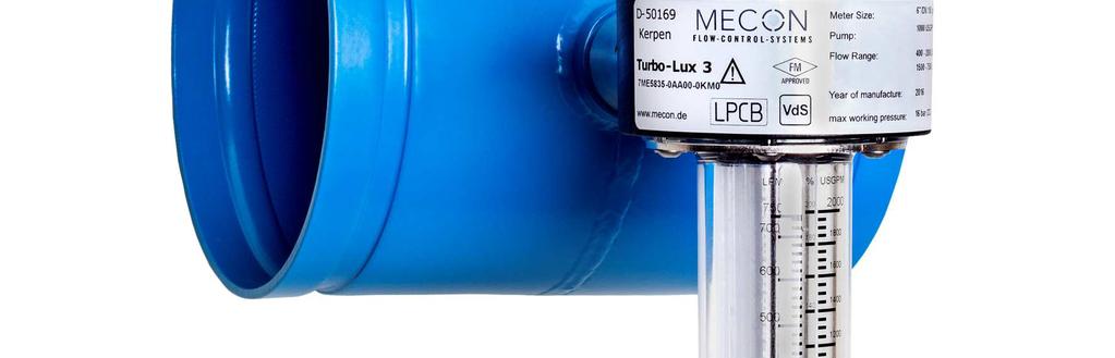
7 DEVICE DESCRIPTION 2.2 Nameplate Fig. 2 Nameplate bypass meter Turbo-Lux Description code / Order code 2 Nominal size and process connection 3 Flow range (USGPM) 4 Flow range (LPM) 3 4 Fig. 3 Nameplate orifice plate 7

8 INSTALLATION AND MODE OF OPERATION 3 INSTALLATION AND MODE OF OPERATION 3.1 Installation notes Information! All instruments are carefully checked for proper function before shipment. Check immediately on receipt, the outer packing carefully for damage or signs of improper handling. Report damage to the carrier and your locale sale staff. In such cases, a description of the defect, the type and the serial number of the device is indicated. Unpack the unit carefully to avoid damage. Check the completeness of the delivery against the packing list. Check the name plate, if the delivered flow meter according to your order. Special requirements VdS: The version with rolled grooved ends may only be used in combination with VdS-approved pipe couplings manufactured by Anvil (Gruvlok mechanical grooved couplings), Jinan Meide (casting couplings type 1G), Minimax, Modgal, Tyco (Grinnell Mechanical und G-Fire steel IPS couplings) and Victaulic (except pipe couplings of the type "Style 77"). 8
.")
. The connected pipes have to be of the same size as the orifice plate. Fig.")
9 INSTALLATION AND MODE OF OPERATION 3.2 Installation instructions Installation of the orifice plate Before and after the orifice plate a straight calming section is provided as a function of the nominal diameter (D). When using valves and fittings before the orifice plate, an inlet path of min. 10 x D is always required. For the standard version an inlet path of min. 10 x D and an outflow zone of min. 5 x D is required (fig. 4). The connected pipes have to be of the same size as the orifice plate. Fig. 4 Inlet path and outflow zone For some flow ranges a special version for shortened inlet path of 5 x D and shortened outflow zone of min. 2 x D is available (fig. 4). Before installation, following conditions have to be observed:» A straight inlet path of 5 x D is required. A longer inlet path is not allowed.» The inlet path has to be connected directly to a one quarter pipe. Fig. 5 Shortened inlet path and outflow zone The installation can be in any line routing - horizontal to vertical - place (fig. 6). However, it is important to ensure that the flow direction of the arrow marked on the device and corresponds to the differential pressure sampling tube (fig. 9/10, pos. 7) is in the horizontal position. 9

10 INSTALLATION AND MODE OF OPERATION For attachment of the bypass meter, sufficient clearance must be provided. Important for the compliance of the measuring tolerance is the central mounting of the pipeline. The center offset must not exceed 0.5 mm. Fig. 6 Examples of installation Mounting the bypass meter The bypass meter is only compatible with the delivered orifice plate. Please make sure that the serial number of the orifice plate and the bypass meter are similar before installation. Before loosening the cap (fig. 9/10, pos. 10), the pipeline must be emptied to prevent the escape of liquids. The meter is plugged and screwed with a nut (fig. 9, pos. 9). It must always be mounted vertically so that the float (fig. 9, pos. 4) can move freely in the tube. About foreign bodies that have come behind the filter must be removed (see 7.2). The tightening of the nut or the cap should be done by hand as possible. The threads must - for example be slippery - by fat. To avoid air strikes, the tube should be slowly filled with water. 3.3 Mode of operation The orifice plate flowmeter Turbo-Lux 3 consists of an orifice plate (fig. 9/10, pos. 1) for stationary installation and a portable bypass meter (fig. 9, pos. 2). The bypass meter contains a conical glass tube (fig. 9, pos. 3) with float (fig. 9, pos. 4). The water flows vertically from top to bottom through the flow tube at the upper end of a side panel (fig. 9, pos. 5) is arranged. A filter (fig. 9, pos. 13) at the inlet largely prevents the ingress of foreign bodies. Inlet and outlet port for the bypass to be measured are arranged concentrically, so that an easy to combine with the stationary primary element. 10
 of the float: 1 1 Reference point Fig.")

11 START-UP 4 START-UP Read the exact value when a consistent flow has been attained and the float has reached a stable position. The pipeline must always be filled. Read the value at the greatest diameter (upper edge) of the float: 1 1 Reference point Fig. 7 Float For the bypass meter it is important that when starting up the pump, the shut-off- /control valve of the bypass orifice is opened min. 30% to avoid hydraulik shocks or pressure surges that could damage the bypass meter. Fig. 8 Rotation bypass meter When the bypass meter is commissioned or set into operation, bubbles of air will initially accumulate at the top part, which must be removed. For this purpose, the union nut (fig. 9, pos. 9) must be somewhat loosened during operation and the device must be rotated by 360, so that the air bubbles can escape. Then the bypass meter has to be positioned vertically and the union nut has to be tightened once again. Before pressure test in pipes, the bypass meter has to be disassembled and the connection of the orifice plate has to be screwed pressure-tight with the cap. 11
12 START-UP Read the exact value On the scale the flow is printed in LPM (liters per minute respectively dm³/min.), USGPM (U.S. gallons per minute) and as percentage (100% = rated power of the pump) for each nominal size and range. The following table provides more information about the scale display. Nominal Size Pump rating (USGPM) Flow range (USGPM) Step (USGPM) Graduatio n (USGPM) Flow range (Ipm) Step (Ipm) Graduation (lpm) 2 /DN /2 /DN /DN /DN /DN /DN /DN /DN /DN /DN /DN /DN /DN /DN /DN /DN /DN /DN /DN /DN Table 1 Scale graduation After device usage After the measurement, the bypass meter is unscrewed, emptied and put back into the packaging. However, make sure in advance that the pipeline is empty and without pressure. The open orifice plate must be sealed pressure-tight with the cap again. 12
13 TECHNICAL DATA 5 TECHNICAL DATA Measuring principle Input» Nominal Size» Pressure limit Measuring accuracy Application conditions» Temperature limit» Medium Design/ Material» Orifice plate 2"/DN 50-4"/DN 100» 6"/DN "/DN 300 Orifice plate flowmeter with variable flowmeter as indication 2"/DN 50 grooved ends (Ø60,3 mm) 2½"/DN 65 grooved ends (Ø76,1 mm) 3"/DN 80 grooved ends (Ø88,9 mm) 4"/DN 100 grooved ends (Ø114,3 mm) 6"/DN 150 grooved ends (Ø165,1 mm) 6"/DN 150 grooved ends (Ø168,3 mm) 8"/DN 200 grooved ends (Ø219,1 mm) 10"/DN 250 grooved ends (Ø273,0 mm) 12"/DN 300 grooved ends (Ø323,9, mm) PN 16 (232 psig) ±2 % of full scale value (FM) ±5 % of measured value (LPCB) ±2,5 % of full scale value (VdS) +4 C to +50 C (+39 F to +122 F) Water Housing tube in stainless steel with turned grooved connection coated steel with rolled grooved connection /optional in stainless steel» Differential pressure sampling tube» Float» Bypass orifice» Filter» Seal Brass Stainless steel Stainless steel Stainless steel NBR Certifications FM Approval LPCB Certificate Number 1385a VdS G
14 TECHNICAL DATA 5.1 Dimensions and weights 1 Housing tube 8 O-Ring 2 Bypass meter 9 Screw cap 3 Measuring tube 10 Cap 4 Float 11 O-Ring 5 Bypass orifice 12Seal 7 Differential pressure 13Filter Fig. 9 Turbo-Lux 3 orifice plate and bypass meter, Drawing and dimensions 2 /DN 50-4 /DN 100 Fig. 10 Turbo-Lux 3 orifice plate, Drawing and dimensions 6"/DN "/DN
15 TECHNICAL DATA Nominal Size dimensions mm (inch) Weight A (approx.) ØD ØI incl. packing kg (lbs) 2"/DN (2.362) 60,3 (2.374) 53 (2.087) 2,0 (4.409) 2½"/DN (2.677) 76,1 (2.996) 66 (2.598) 2,1 (4:630) 3"/DN (2.952) 88,9 (3.499) 80 (3.150) 2,3 (5.071) 4"/DN (3.425) 114,3 (4.499) 100 (3.937) 3,2 (7.055) 6"/DN (4.449) 165,1 (6.496) - 4,9 (10.803) 6"/DN (4.488) 168,3 (6.626) - 4,9 (10.803) 8"/DN (5.511) 219,1 (8.626.) - 6,4 (14.110) 10"/DN (6.535) 273,0 (10.784) - 8,5 (18.739) 12"/DN (7.559) 323,9 (12.752) - 11,0 (24.251) Table 2 Dimension and weights Nominal Size Ø D Min. thickness mm (inch) min. mm (inch) max. mm (inch) 2"/DN 50 60,3 (2.374) 2,6 (0.102) 3,6 (0.142) 2½"/DN 65 76,1 (2.996) 2,6 (0.102) 2,9 (0.114) 3"/DN 80 88,9 (3.499) 2,9(0.114) 4,0 (0.157) 4"/DN ,3 (4.499) 3,2 (0.126) 4,5 (0.177) 6"/DN ,1 (6.496) 4,0 (0.157) 5,0 (0.177) 6"/DN ,3 (6.626) 4,0 (0.157) 4,5 (0.177) 8"/DN ,1 (8.626) 4,5 (0.177) 4,5 (0.177) 10"/DN ,0 (10.748) 5,0 (0.197) 5,0 (0.197) 12"/DN ,9 (12.752) 5,6 (0.220) 5,6 (0.220) Table 3 Dimensions tube of inlet path and outflow zone 15
16 DESCRIPTION CODE 6 DESCRIPTION CODE Standard version for inlet path 10 x D and outflow zone 5 x D 1 Measuring accuracy certificate for orifice plate flowmeter (SET) 0 without 1 with 2 Nominal size/pump rating Nominal size Pump rating Flow range Approval grooved ends USGPM USGPM LPM FM LPCB VdS EB 2"/DN 50 (Ø60,3) X X X FC 2½"/DN 65 (Ø76,1) * X X GD 3"/DN 80 (Ø88,9) X X X GE 3"/DN 80 (Ø88,9) X X X HF 4"/DN 100 (Ø114,3) X X X HG 4"/DN 100 (Ø114,3) X X X HH 4"/DN 100 (Ø114,3) X X X HJ 4"/DN 100 (Ø114,3) X X X XK 6"/DN 150 (Ø165,1) X X XL 6"/DN 150 (Ø165,1) X X XM 6"/DN 150 (Ø165,1) X X XN 6"/DN 150 (Ø165,1) X X KK 6"/DN 150 (Ø168,3) * X X KL 6"/DN 150 (Ø168,3) X X X KM 6"/DN 150 (Ø168,3) X X X KN 6"/DN 150 (Ø168,3) X X X LP 8"/DN 200 (Ø219,1) X X X LQ 8"/DN 200 (Ø219,1) X X X LR 8"/DN 200 (Ø219,1) X X X LS 8"/DN 200 (Ø219,1) ** X X X MT 10"/DN 250 (Ø273,0) * - - MU 10"/DN 250 (Ø273,0) * - - MV 10"/DN 250 (Ø273,0) * - - NW 12"/DN 300 (Ø323,9) * - - *Approval in process, **VdS-limited flow range 3 /S Housing tube made in stainless steel; option for nominal size 6"/DN 150 up to 12"/DN
17 DESCRIPTION CODE Special version for inlet path 5 x D and outflow zone 2 x D 1 Measuring accuracy certificate for orifice plate flowmeter (SET) 0 without 1 with 2 Nominal size/pump rating Nominal size Pump rating Flow range Approval grooved ends USGPM USGPM LPM FM LPCB VdS EB 2"/DN 50 (Ø60,3) X X X FC 2½"/DN 65 (Ø76,1) * X X GD 3"/DN 80 (Ø88,9) X X X GE 3"/DN 80 (Ø88,9) X X X HF 4"/DN 100 (Ø114,3) X X X HG 4"/DN 100 (Ø114,3) X X X HH 4"/DN 100 (Ø114,3) X X X HJ 4"/DN 100 (Ø114,3) X X X XK 6"/DN 150 (Ø165,1) X X XL 6"/DN 150 (Ø165,1) X X XM 6"/DN 150 (Ø165,1) X X KK 6"/DN 150 (Ø168,3) * X X KL 6"/DN 150 (Ø168,3) X X X KM 6"/DN 150 (Ø168,3) X X X LP 8"/DN 200 (Ø219,1) X X X LQ 8"/DN 200 (Ø219,1) X X X *Approval in process 3 /S Housing tube made in stainless steel; option for nominal size 6"/DN 150 bis 8"/DN
18 SERVICE 7 SERVICE 7.1 Storage Store the emptied device in a dry and dust-free place. Keep away from direct and permanent sun and heat. Keep away from direct external load to the device. The storage temperature range is -20 to +60 C (-4 F to +140 F). 7.2 Maintenance If the filter is blocked by deposits (fig. 9, pos. 13) the flowmeter must be returned to the manufacturer to be cleaned and tested. Ensure that the O-ring (fig. 9, pos. 8) and the M 30 x 1.5 thread of the orifice plate are lubricated with grease. 7.3 Returning the device to the manufacturer All flowmeters were manufactured in accordance with the highest quality standards and were thoroughly tested prior to shipment. Should you nevertheless need to return a device to MECON GmbH please observe the following points: Attention! According to the latest waste disposal directives, the owner/customer is responsible for the waste management of hazardous and toxic waste. For reasons of environmental protection and safeguarding the health and safety of our personnel, all devices sent to MECON GmbH to be repaired must be free of toxic and hazardous substances. This also applies to cavities of the devices. If necessary, the customer is kindly requested to neutralize or rinse the devices before returning them to MECON GmbH. The customer has to confirm this by filling in an appropriate form and to be added to the device, which is available for download on the MECON website:» 18
19 SERVICE 7.4 Disposal Attention! For disposal of equipment are the regulations in your country comply. 19
20 MECON GmbH Röntgenstr. 105 D Kerpen Germany Tel.: +49 (0) Fax: +49 (0) Web:
Installation and Operating Instructions DDM-DS11 DDM-DS11-MS1 DDM-DS11-MS2
 Installation and Operating Instructions Differential-Pressure Flow -MS1 -MS2 2 Table of Contents 1. Foreword...3 2. Safety...3 2.1. Symbol and meaning...3 2.2. General safety directions and exemption from
Assembly and operating Instructions. Bypass Flow Meter DST
 Assembly and operating Instructions Bypass Flow Meter 2 Contents 1. Foreword... 3 2. Safety... 3 2.1. Symbol and meaning... 3 2.2. General safety directions and exemption from liability... 3 2.3. Intended
Assembly and operating Instructions Bypass Flow Meter DST
 Assembly and operating Instructions Bypass Flow Meter 2 Contents 1. Foreword... 3 2. Safety... 3 2.1. Symbol and meaning... 3 2.2. General safety directions and exemption from liability... 3 2.3. Intended
Mounting and Operating Instructions EB 8135/8136 EN. Series V2001 Valves Type 3535 Three-way Valve for Heat Transfer Oil
 Series V2001 Valves Type 3535 Three-way Valve for Heat Transfer Oil Type 3535 Three-way Valve with bellows seal and rod-type yoke (partial view) Mounting and Operating Instructions EB 8135/8136 EN Edition
OFFICINE OROBICHE S.p.A. 1/7 INSTRUCTION MANUAL FOR FLOW SWITCHES PL SERIES
 OFFICINE OROBICHE S.p.A. 1/7 INSTRUCTION MANUAL FOR FLOW SWITCHES PL SERIES 1.INSTRUMENT DESCRIPTION Flow switches PL series are designed to be mounted in an upright position along horizontal pipes. These
Assembly and operating Instructions RA 60 / FA 60
 VA flow meters Assembly and operating Instructions Variable Area Flow Meters 2 contents 1. Foreword...3 2. Safety...3 2.1. Symbol and meaning...3 2.2. General safety directions and exemption from liability...3
POSITIVE DISPLACEMENT FLOWMETERS
 MS345BR 0408 0001 POSITIVE DISPLACEMENT FLOWMETERS M4 BRONZE SERIES INSTRUCTION MANUAL M4 Pulse; M4 Standard LCD; M4 Deluxe LCD; From serial No.CXXXX TO THE OWNER Please take a few minutes to read through
Mounting and Operating Instructions EB 5863 EN. Electric Control Valves. Pneumatic Control Valve
 Electric Control Valves Types 3226/5857, 3226/5824, 3226/5825, 3226/5757-7, 3226/5724-8, 3226/5725-7, 3226/5725-8 Pneumatic Control Valve Type 3226/2780 Type 3226/5857 Type 3226/5757-7 Type 3226/2780-2,
SMB. Assembly and operating instructions Sprinkler measuring orifice SMB/SMB-OE. Sprinkler measuring orifice
 Assembly and operating instructions /-OE Fon: +49 2065 9609-0 Fax: +49 2065 9609-22 Internet: www.kt-web.de e-mail: info@kt-web.de 2 1. General...3 1.1 Exclusion of liability...3 2. Safety...4 2.1 General
DAKOTA INSTRUMENTS OPERATING MANUAL ACR ACRYLIC FLOW METERS
 OPERATING MANUAL ACR ACRYLIC FLOW METERS DAKOTA INSTRUMENTS Website: http://dakotainstruments.com E-mail: info@dakotainstruments.com Toll Free USA and Canada: 1(800) 879-7713 Tel. 1+(845) 770-3200 Fax.
Operating manual Separator
 Operating manual Separator Sheet no. AS/4.1.141.1.1 issue 20.08.2014 Contents Section Title Page 0 Introduction... 1 1 Intended use......1 2 Marking of the fitting... 1 3 Safety instructions... 2 4 Transport
WATERFLUX 3070 Quick Start
 WATERFLUX 3070 Quick Start Battery powered electromagnetic water meter Electronic Revision ER 4.3.0_ up to ER 4.3.4_ (SW.REV 4.2.2_ up to 4.2.5_) KROHNE CONTENTS WATERFLUX 3070 1 Safety instructions 4
Tension Meter. Edition FT 03.E. FT Series. Instruction Manual. Valid as of: Please keep the manual for future reference!
 Tension Meter FT Series S C H M I D T c o n t r o l i n s t r u m e n t s Edition FT 03.E Model FT Instruction Manual Valid as of: 01.09.2011 Please keep the manual for future reference! Contents 1 Warranty
Mounting and Operating Instructions EB 8039 EN. Type 3351 Pneumatic On/off Valve. Type 3351 Pneumatic On/off Valve. Type 3351 Pneumatic On/off Valve
 Type 3351 Pneumatic On/off Valve Type 3351 Pneumatic On/off Valve Type 3351 Pneumatic On/off Valve Version with handwheel Mounting and Operating Instructions EB 8039 EN Edition May 2016 Definition of signal
Mounting and Operating Instructions EB 8222 EN. Type 3310/AT and Type 3310/3278 Pneumatic Control Valves. Type 3310 Segmented Ball Valve
 Type 3310/AT and Type 3310/3278 Pneumatic Control Valves Type 3310 Segmented Ball Valve Fig. 1 Type 3310/3278 with positioner Fig. 2 Type 3310/AT Mounting and Operating Instructions EB 8222 EN Edition
TIDALFLUX 2300 F Quick Start
 Quick Start Electromagnetic flow sensor for partially filled pipes The documentation is only complete when used in combination with the relevant documentation for the signal converter. KROHNE CONTENTS
Orifice flowmeter F O N4
 Special features Suitable for any mounting positions without reduction in accuracy Complies with requirements for treatment and disinfection of swimming/ bathing pools (DIN 9 643) Simple installation Direct
Type Operating Instructions. Bedienungsanleitung Manuel d utilisation. 2/2-Way Solenoid Valve 2/2-Wege-Magnetventil Électrovanne à 2/2 voies
 Type 5282 2/2-Way Solenoid Valve 2/2-Wege-Magnetventil Électrovanne à 2/2 voies Operating Instructions Bedienungsanleitung Manuel d utilisation 1 OPERATING INSTRUCTIONS The operating instructions contain
Type Operating Instructions. Bedienungsanleitung Manuel d utilisation. 2/2-Way Solenoid Valve 2/2-Wege-Magnetventil Électrovanne à 2/2 voies
 Type 5282 2/2-Way Solenoid Valve 2/2-Wege-Magnetventil Électrovanne à 2/2 voies Operating Instructions Bedienungsanleitung Manuel d utilisation Contents 1 Operating Instructions... 2 2 Authorized use...
OPTIFLUX 2000 Quick Start
 OPTIFLUX 2000 Quick Start Electromagnetic flow sensor The documentation is only complete when used in combination with the relevant documentation for the signal converter. KROHNE CONTENTS OPTIFLUX 2000
GRINNELL Model B302 and Model BN302 Grooved End Butterfly Valves with Gear Operators or Lever-Lock Operators General Description
 Technical Services -00- +-0--0 www.grinnell.com GRINNELL Model B0 and Model BN0 Grooved End Butterfly Valves with Gear Operators or Lever-Lock Operators General Description The GRINNELL Models B0 and BN0
Mounting and Operating Instructions EB 8097 EN. Type and Type Pneumatic Control Valves
 Type 3347-1 and Type 3347-7 Pneumatic Control Valves Type 3347-7, cast body with welding ends Type 3347-7, bar stock body with threaded connections Mounting and Operating Instructions EB 8097 EN Edition
Full View Flow Indicator
 Full View Flow Indicator Threaded and Flanged Process Connection Installation / Operation / Maintenance Manual P.O. Box 1116 Twinsburg, OH 44087 Phone: 330/405-3040 Fax: 330/405-3070 E-mail: view@ljstar.com
Mounting and Operating Instructions EB 8111/8112 EN. Series V2001 Valves Type 3321 Globe Valve
 Series V2001 Valves Type 3321 Globe Valve Type 3321 Globe Valve with rod-type yoke and Type 3372 Electropneumatic Actuator (350 cm²) Mounting and Operating Instructions EB 8111/8112 EN Edition June 2013
Mounting and Operating Instructions EB 5894 EN. Electric control valves with jet pump. Flanged version of valve with jet pump
 Electric control valves with jet pump Type 3267/5824, Type 3267/5825, Type 3267/3374, Type 3267/3274 Pneumatic control valves with jet pump Type 3267-1, Type 3267-7 Flanged version of valve with jet pump
Safety. Operating instructions Solenoid valve for gas VG 6 VG 15/10 DANGER. Contents WARNING CAUTION. Changes to edition 07.15
 17 Elster GmbH Edition 1.17 Translation from the German 519 D F NL I E DK S N P GR TR CZ PL RUS H www.docuthek.com Operating instructions Solenoid valve for gas VG VG 15/1 Contents Solenoid valve for gas
Industrial Turbo Meters, Sizes 2" through 6"
 Industrial Turbo Meters Sizes 2" through 6" TUR-UM-00530-EN-19 (October 2014) User Manual Industrial Turbo Meters, Sizes 2" through 6" User Manual CONTENTS Scope of the Manual 5 Specifications 5 Product
Tension Meter. PT Series. Instruction Manual PT-100-L. Valid as of: Please keep the manual for future reference!
 Tension Meter S C H M I D T PT Series c o n t r o l i n s t r u m e n t s Edition PT 01.0.E Model PT-100 PT-100-L Instruction Manual Valid as of: 15.04.2011 Please keep the manual for future reference!
Swing Piston Compressors and Vacuum Pumps
 Swing Piston Compressors and Vacuum Pumps NPK 018 AC Pressure NPK 018 DC Pressure NPK 018 AC Vacuum NPK 018 DC Vacuum Operating and Installation Instructions Read and observe these Operating and Installation
Short-tube VA flow meter SGK 1-3
 Assembly and operating Instructions Short-tube VA flow meter SGK 1-3 Contents 1 Foreword...3 2 Safety...3 2.1 Symbol and meaning...3 2.2 General safety directions and exemption from liability...3 2.3 Intended
APCO ASR-400/450 SEWAGE AIR RELEASE VALVES
 APCO ASR-400/450 SEWAGE AIR RELEASE VALVES Instruction D12005 December 2012 Instructions These instructions provide installation, operation and maintenance information for the APCO ASR- 400/450 Sewage
Electromagnetic flowmeters
 02/97 Electromagnetic flowmeters Primary heads Installation instructions ECOFLUX IFS 1000 F Compact flowmeters IFM 1010 K IFM 1080 K CONTENTS Installation in the pipeline Pages 4-5 and 7-8 Grounding Pages
Storage, operating and maintenance instructions for AZ plug valves and Standard valves
 ARMATUREN Plug - Valves metallic with PTFE Sleeve 2-7 way Storage, operating and maintenance instructions for AZ plug valves and Standard valves Plug - Valves FEP/PFA - lined, 2-3 way Butterfly - Valves
Angle seat valve with diaphragm actuator VZXA-...-M
 Angle seat valve with diaphragm actuator VZXA-...-M Instructions Operating (Translation of the original instructions) Festo AG & Co. KG Ruiter Straße 82 73734 Esslingen Germany +49 711 347-0 www.festo.com
GRINNELL MODEL CB800 CIRCUIT BALANCING VALVE INSTALLATION & SETTING HANDBOOK
 Technical Services 866-500-4768 +-40-78-8220 GRINNELL MODEL CB800 CIRCUIT BALANCING VALVE INSTALLATION & SETTING HANDBOOK AUGUST 20 IH-4500 Table of Contents Contents General Description.... 3 Dimensional
APCO CRF-100A RUBBER FLAPPER SWING CHECK VALVES
 APCO CRF-100A RUBBER FLAPPER SWING CHECK VALVES Instruction D12043 June 2016 DeZURIK Instructions These instructions provide installation, operation and maintenance information for APCO CRF-100A Rubber
Operating Instructions for Oval Wheel Flowmeter. Model: DOC
 Operating Instructions for Oval Wheel Flowmeter Model: DOC We don t accept warranty and liability claims neither upon this publication nor in case of improper treatment of the described products. The document
MODEL 200 MULTI-JET FLOW METER
 MODEL 200 MULTI-JET FLOW METER - For Water Applications - INSTALLATION & INSTRUCTION MANUAL 8635 Washington Avenue Racine, Wisconsin 53406 Toll Free: 800.235.1638 Phone: 262.639.6770 Fax: 262.417.1155
Flow-Through Fitting ARF 215
 Flow-Through Fitting ARF 215 Standard Models Model for Pressurized Sensors Latest Product Information: www.knick.de Warranty Defects occurring within 1 year from delivery date shall be remedied free of
Installation, Operation, and Maintenance Manual
 Industrial Process Installation, Operation, and Maintenance Manual Series PBV Plastic Lined Ball Valve Table of Contents Table of Contents Introduction and Safety...2 Safety message levels...2 User health
Mounting and Operating Instructions EB 8111/8112 EN. Valve Series V2001 Globe Valve Type 3321
 Valve Series V2001 Globe Valve Type 3321 Fig. 1 Type 3321 Valve with mounted rod-type yoke for pneumatic or electric actuators (partial view) Mounting and Operating Instructions EB 8111/8112 EN Edition
Assembly and operating Instructions
 VA flow meters Assembly and operating Instructions Variable Area Flow Meters 2 Contents 1. Foreword...3 2. Safety...3 2.1. Symbol and meaning...3 2.2. General safety directions and exemption from liability...3
SENSOFIT RET 5000 Technical Datasheet
 SENSOFIT RET 5000 Technical Datasheet Manual retractable assembly Variable immersion length up to 700 mm With ball valve for easy sensor exchange without process interruptions Bayonet coupling for easy
Assembly and Maintenance Manual Type AS
 Assembly and Maintenance Manual Type AS Hatschekstr.36 69126 Heidelberg Germany Tel +49(0)6221 30470 Fax +49(0)6221 304731 info@stieber.de www.stieber.de Date of issue: 30.05.2018 GB Revision: 0 U:\EngUsers\!ProduktDoku\1AAA_Einbauerklaerung_Wartungsanleitung_Konformitaetserklaerung\1AAA_Wartungsanleitungen\Orginal_Worddatei\_AS.docx
Installation, Operation, and Maintenance Manual
 Industrial Process Installation, Operation, and Maintenance Manual Series PBFV Plastic Lined Butterfly Valve - Lug and Wafer Style Table of Contents Table of Contents Introduction and Safety...2 Safety
Agxcel GX12i Chemical Injection System
 Agxcel GX12i Chemical Injection System Table of Contents System Contents... 3 Specifications... 4 Safety Precautions and Tips... 5 Operations... 6 Installation... 7 Maintenance... 8-9 Troubleshooting...
Grinnell Grooved Fire Protection Products Grooved Fittings
 Technical Services: Tel: (800) 38-932 / Fax: (800) 79-5500 www.tyco-fire.com Grinnell Grooved Fire Protection Products Grooved Fittings General Description LPCB Vd S The grooved fittings provide an economical
Mounting and Operating Instructions EB 8048 EN. Type and Type Pneumatic Control Valves Type 3249 Aseptic Angle Valve
 Type 3249-1 and Type 3249-7 Pneumatic Control Valves Type 3249 Aseptic Angle Valve Ball body version Special version with packing Type 3249-7 Control Valve with Type 3277 Actuator and integrated positioner
Nor East. Instructions Safety Messages. Inspection. Parts. DeZURIK Service. Type 05 Pneumatic Actuator Used With Globe Valves
 Instructions Safety Messages These instructions are intended for personnel who are responsible for installation, operation and maintenance of your DeZURIK Actuator. All safety messages in the instructions
Type Operating Instructions. Bedienungsanleitung Manuel d utilisation. 2/2-way solenoid valve 2/2-Wege-Magnetventil Électrovanne 2/2 voies
 Type 5404 2/2-way solenoid valve 2/2-Wege-Magnetventil Électrovanne 2/2 voies Operating Instructions Bedienungsanleitung Manuel d utilisation Contents 1 Operating instructions...2 2 Intended use...3 3
Compensation unit AGE-XY 50-80
 Translation of the origninal manual Compensation unit AGE-XY 50-80 Assembly and operating manual Superior Clamping and Gripping Imprint Imprint Copyright: This manual remains the copyrighted property of
Spare Parts List Return line filter RF
 Spare Parts List Return line filter up to 15000 l/min, up to 25 bar 30 60 110 160 240 330 450 580 660 950 1300 2500 4000 5200 6500-7800 15000 1. MAINTENANCE 1.1 GENERAL Please follow the maintenance instructions!
Accessories for Wind Power Inverter WINDY BOY PROTECTION BOX 400 / 500 / 600
 Accessories for Wind Power Inverter WINDY BOY PROTECTION BOX 400 / 500 / 600 Installation Guide WBP-Box-IEN103320 IMEN-WBP-BOX Version 2.0 EN SMA Solar Technology AG Table of Contents Table of Contents
Installation, Operation, and Maintenance Manual
 Industrial Process Installation, Operation, and Maintenance Manual Cam-Tite Ball Valve Table of Contents Table of Contents Introduction and Safety...2 Safety message levels...2 User health and safety...2
INSTALLATION, OPERATION, AND MAINTENANCE MANUAL WELKER FILTER
 INSTALLATION, OPERATION, AND MAINTENANCE MANUAL WELKER FILTER MODELS F-7 F-8 DRAWING NUMBERS AD045B[ ] AD046BB AD046BO MANUAL NUMBER IOM-113 REVISION Rev. B, 3/22/2017 TABLE OF CONTENTS SAFETY 3 1. PRODUCT
Crispin Valves Operating Guide. Crispin
 Crispin Valves Operating Guide Crispin Since 1905 Crispin Multiplex Manufacturing Co. 600 Fowler Avenue Berwick, PA 18603 1-800-AIR-VALV T: (570) 752-4524 F: (570) 752-4962 www.crispinvalve.com sales@crispinvalve.com
Electropneumatic Converters i/p Converters Type 6111 Mounting and Operating Instructions EB 6111 EN
 Electropneumatic Converters i/p Converters Type 6111 Fig. 1 Type 6111 in standard version Fig. Type 6111 mounted on a supply air manifold Fig. 3 Type 6111 in field enclosure Mounting and Operating Instructions
MDP 1000 OPERATING INSTRUCTIONS PUMP MDP 1000 OPERATING INSTRUCTIONS
 MDP 1000 OPERATING INSTRUCTIONS PUMP MDP 1000 OPERATING INSTRUCTIONS SAINT-GOBAIN PERFORMANCE PLASTICS FRANCE SAINT-GOBAIN PERFORMANCE PLASTICS EADAC DES BERTHILLIERS 7301 Orangewood Avenue F-71850 CHARNAY
KSZ 10B Current Probe Calibrator. Instruction Manual
 KSZ 10B Current Probe Calibrator Instruction Manual Copyright 2011 PMK GmbH All rights reserved. Information in this publication supersedes that in all previously published material. Specifications are
INSTALLATION, OPERATION, AND MAINTENANCE MANUAL WELKER FILTER DRYER
 INSTALLATION, OPERATION, AND MAINTENANCE MANUAL WELKER FILTER DRYER MODEL F-31 DRAWING NUMBER AD044CP MANUAL NUMBER IOM-185 REVISION Rev. A, 4/23/2018 TABLE OF CONTENTS SAFETY 3 1. PRODUCT INFORMATION
Original Operating Manual
 matev GmbH Nürnberger Str. 50 90579 Langenzenn T +49 (0) 9101 9087-0 F +49 (0) 9101 9087-20 info@matev.eu www.matev.eu Original Operating Manual Front Power System und Front PTO shaft FPS- JD X 950 R for
Installation, Operation, and Maintenance Manual
 Installation, Operation, and Maintenance Manual API 6D Piston Check Valve - IOM: Installation, Operation and Maintenance Manual 1/16 Table of Contents 1 INTRODUCTION... 3 1.1 SCOPE... 3 1.2 DISCLAIMER...
Angle seat valve with piston actuator VZXA-...-K
 Angle seat valve with piston actuator VZXA-...-K Festo AG & Co. KG Postfach 73726 Esslingen Germany +49 711 347-0 www.festo.com 3 Further information Accessories www.festo.com/catalogue Spare parts www.festo.com/spareparts
AquaMaster4 Electromagnetic flowmeter flanged sensor
 ABB MEASUREMENT & ANALYTICS OPERATING INSTRUCTION AquaMaster4 Electromagnetic flowmeter flanged sensor The ideal flowmeter for potable water distribution networks, revenue metering and irrigation applications
Positive Displacement Flowmeters GM007 series instruction manual
 MS499G 0603 0003 Positive Displacement Flowmeters GM007 series instruction manual GM007 Pulse Meter From serial No. CXXXX To the owner Thank you for purchasing a GPI GM GPI by telephone or fax.] Series
Installation and Operating Instructions for EAS -NC clutch Type 45_. _. _ Sizes 02 and 03
 Table of contents: Please read and observe this Operating Instruction carefully! A possible malfunction or failure of the clutch and any damage may be caused by not observing it. Page 1: - Table of contents
Type 6213 EV, 6281 EV
 Type 6213 EV, 6281 EV 2/2-way solenoid valve 2/2-Wege-Magnetventil Électrovanne 2/2 voies Operating Instructions Bedienungsanleitung Manuel d utilisation 1 OPERATING INSTRUCTIONS The operating instructions
Bypass Flow Meter DST
 Assembly and operating Instructions Bypass Flow Meter DST Contents 1 Foreword...3 2 Safety...3 2.1 Symbol and meaning...3 2.2 General safety directions and exemption from liability...3 2.3 Intended use...4
These installation and maintenance instructions must be read in full and completely understood before the installation!
 These installation and maintenance instructions must be read in full and completely understood before the installation! 1. General information on the installation and maintenance instructions These instructions
Angle seat valve with piston actuator VZXA-...-K
 Angle seat valve with piston actuator VZXA-...-K Instructions Operating (Translation of the original instructions) Festo AG & Co. KG Ruiter Straße 82 73734 Esslingen Germany +49 711 347-0 www.festo.com
F-4600 INLINE ULTRASONIC FLOW METER Installation and Operation Guide
 F-4600 INLINE ULTRASONIC FLOW METER Installation and Operation Guide 11451 Belcher Road South, Largo, FL 33773 USA Tel +1 (727) 447-6140 Fax +1 (727) 442-5699 1054-7 / 34405 www.onicon.com sales@onicon.com
TRANSDUCER INSTRUCTION MANUAL... TYPE SLIM CELL TRANSDUCER. INSTRUCTION NUMBER: AO of 9
 CLEVELAND-KIDDER SLIM CELL TRANSDUCER INSTRUCTION MANUAL... TYPE SLIM CELL TRANSDUCER INSTRUCTION NUMBER: AO-70165 1 of 9 1.0 GENERAL INFORMATION 1.1 RECEIVING AND UNPACKING Handle and unpack the equipment
Design and applications
 Design and applications The DDM-DS11 measuring system measures and monitors the flow rate of liquids and gases. The device works according to the principle of differential pressure. The differential pressure
ACTIVAL Two-way Ball Valve with Threaded-end Connection
 Specifications/Instructions ACTIVAL Two-way Ball Valve with Threaded-end Connection General ACTIVAL Model VY5302A is a two-way ball valve with threaded-end connection (ISO 7-1: 1994). It proportionally
SPARK PLUG CLEANING KIT OPERATING MANUAL
 SPARK PLUG CLEANING KIT OPERATING MANUAL Spark Plugs - Tools & Accessories P/N 01.20.002 Rev. 08/2015 Copyright Copyright 2015 MOTORTECH GmbH. All rights reserved. Distribution and reproduction of this
Oil-free piston compressors KK and piston vacuum pumps KV
 Oil-free piston compressors KK and piston vacuum pumps KV Installation and Operating Instructions 0678106030L02 1707V003 Contents Important information 1 About this document 2 1.1 Warnings and symbols
Flowmeter F I Gardex. Connection and installation instructions. Application. Benefits. Design and mode of operation
 The baffle plate (b) causes a back-pressure in the medium, and the balance beam (c) is deflected. This movement is transmitted via the beam to the indicator mechanism (e) using a bellows bushing (d). gear
Instructions for installation, operation and maintenance of: GATE VALVE
 Instructions for installation, operation and maintenance of: GATE VALVE GEN GAC GAF/GENF TERMOVENT SC Temerin Republic of Serbia Instruction for installation, operation and maintenance: Table of Contents
Thermowell For sanitary applications Model TW22
 Thermowells Thermowell For sanitary applications Model TW22 WIKA data sheet TW 95.22 Applications Sanitary applications Food and beverage industry Bio and pharmaceutical industry, production of active
MODEL 200 MULTI-JET FLOW METER
 MODEL 200 MULTI-JET FLOW METER - For Water Applications - INSTALLATION & INSTRUCTION MANUAL 8635 Washington Avenue Racine, Wisconsin 53406 Technical Toll-Free: 877.722.4631 Sales Toll-Free: 800.235.1638
Assembly and Maintenance Manual Type ASNU
 Assembly and Maintenance Manual Type ASNU Hatschekstr.36 69126 Heidelberg Germany Tel +49(0)6221 30470 Fax +49(0)6221 304731 info@stieber.de www.stieber.de Date of issue: 30.05.2018 GB Revision: 0 U:\EngUsers\!ProduktDoku\1AAA_Einbauerklaerung_Wartungsanleitung_Konformitaetserklaerung\1AAA_Wartungsanleitungen\Orginal_Worddatei\_ASNU.docx
Condensate Drain Valve AK 45. Original Installation Instructions English
 Condensate Drain Valve AK 45 EN English Original Installation Instructions 810467-03 1 Contents Important Notes Page Usage for the intended purpose...4 Safety note...4 Danger...4 Attention...4 PED (Pressure
Series 250 Pneumatic Control Valves Type and
 Series 250 Pneumatic Control Valves Type 3252-1 and 3252-7 Fig. 1 Type 3252 High-pressure Valve with Type 3277 Pneumatic Actuator and Type 3767 i/p Positioner Edition November 1998 Mounting and operating
Electromagnetic flowmeters for water and seewage
 09/97 Electromagnetic flowmeters for water and seewage Primary head Compact flowmeters Installation instructions AQUAFLUX F 0 K 020 K 080 K CONTENTS Storage and transport Pagesn 3-4 Installation in the
Series V2001 Valves Type 3531 Globe Valve for Heat Transfer Oil with pneumatic or electric actuator
 Series V2001 Valves Type 3531 Globe Valve for Heat Transfer Oil with pneumatic or electric actuator DIN version Application Control valves for heat transfer applications using organic media according to
Baumann 24000C Carbon Steel Little Scotty Control Valve Instructions
 Instruction Manual D103356X012 24000C Control Valve Baumann 24000C Carbon Steel Little Scotty Control Valve Instructions CONTENTS Introduction...1 Scope...1 Safety Precautions...1 Maintenance...2 Flow
Installation Operation Maintenance. LSSN Butterfly Valve AGA Approved 50MM - 150MM. QAD#IM6055.REVA
 LSSN Butterfly Valve Installation Operation Maintenance Licence Number: 5326 www.challengervalves.com.au 1 Index 1. INTRODUCTION 1.1 Design Features 3 1.2 Flange and Pipe Compatibility 4 1.3 Operating
Installation and operating manual
 LK product no: 901002 and 901102 501002 and 501102 (JIS) Article no: 74500 Revision: 9 Article no: 74500 Revision: 9 2 (23) Contents 1. General information... 5 2. Safety precautions... 5 2.1 Significance
JET METER INSTRUCTIONS
 UNPACKING Please open and inspect your package upon receipt. Your package was packed with great care and all the necessary packing materials to arrive to you undamaged. If you do find an item that is broken
Operating Manual COST CONTROL - POWER CONSUMPTION MONITOR
 Contents Operating Manual COST CONTROL - POWER CONSUMPTION MONITOR Introduction 1 Intended Use 2 Safety Precautions 3 The Cost Control 4 Features 5 Cost Monitoring 6 Cost Forecasting 7 Instantaneous Power
Mounting and Operating Instructions EB 8097 EN. Pneumatic Control Valves Type and Type
 Pneumatic Control Valves Type 3347-1 and Type 3347-7 Hollow-mold cast body with welding ends Full-mold cast body with threaded connections Fig. 1 Type 3347-7 Control Valve with Type 3277 Actuator and integral
Mounting and Operating Instructions EB 8227 EN. Pneumatic Control Valve Type 3331/BR 31a Special version Type 3331/3278. Type 3331 Butterfly Valve
 Pneumatic Control Valve Type 3331/BR 31a Special version Type 3331/3278 Type 3331 Butterfly Valve Fig. 1 Type 3331/BR 31a (below) and Type 3331/3278 (top) Mounting and Operating Instructions EB 8227 EN
Val-Matic 1-4 Combination Air Valve (Single Housing Type)
") Manual No. ARCO-OM1-3 Val-Matic 1-4 Combination Air Valve (Single Housing Type) Operation, Maintenance and Installation Manual INTRODUCTION... 1 RECEIVING AND STORAGE... 1 DESCRIPTION OF OPERATION... 1
Manual No. ARCO-OM1-3 Val-Matic 1-4 Combination Air Valve (Single Housing Type) Operation, Maintenance and Installation Manual INTRODUCTION... 1 RECEIVING AND STORAGE... 1 DESCRIPTION OF OPERATION... 1
Installation and operating manual Quick closing valve (Bellow sealed) LK product no:
 LK product no:") LK product no: 902002 Article no: 74506 Revision: 2 Contents 1. General information... 3 2. Safety precautions... 3 2.1 Significance of symbols... 3 2.2 Explanatory notes on safety information... 3 3.
LK product no: 902002 Article no: 74506 Revision: 2 Contents 1. General information... 3 2. Safety precautions... 3 2.1 Significance of symbols... 3 2.2 Explanatory notes on safety information... 3 3.
TBP SERIES PUMPS OPERATION & PARTS MANUAL
 TBP SERIES PUMPS OPERATION & PARTS MANUAL EU Declaration of Conformity Finish Thompson Inc. hereby declares that the following machine(s) fully comply with the applicable health and safety requirements
INSTALLATION & SERVICE INSTRUCTION MANUAL W.A. KATES FLOW CONTROLLERS FC VALVE MODELS E THRU M
 INSTALLATION & SERVICE INSTRUCTION MANUAL W.A. KATES FLOW CONTROLLERS FC VALVE MODELS E THRU M IMPORTANT 1. W. A. Kates flow rate controllers are designed to accurately regulate flows and are precision
UD and UC Gear pump unit
 1-19-EN for SKF CircOil or hydraulic lubrication systems General Information The UC and UD gear pump units are vertically or horizontally arranged units that are used in hydraulic or circulating-oil lubrication
Operating & Maintenance Manual For Steam Conditioning Valve
 For Steam Conditioning Valve 1 Table of Contents 1.0 Introduction 3 2.0 Product description 3 3.0 Safety Instruction 4 4.0 Installation and Commissioning 5 5.0 Valve Disassembly 6 6.0 Maintenance 6 7.0
OPTIFLUX 6000 Technical Datasheet
 OPTIFLUX 6000 Technical Datasheet Electromagnetic flow sensor for hygienic and sanitary applications Robust stainless steel housing for hygienic and aseptic operation Fully suitable for CIP and SIP Typical
Positive Displacement Flowmeters GM020 series instruction manual
 MS244G 0603 0003 Positive Displacement Flowmeters GM020 series instruction manual GM020 Pulse Meter From serial No. CXXXX To the owner Thank you for purchasing a GPI GM Series Flow Meter. Please take a