Magnetic Door Jamb Switches (Ground Style) Installation Instructions
|
|
|
- Andrew Bradford
- 5 years ago
- Views:
Transcription

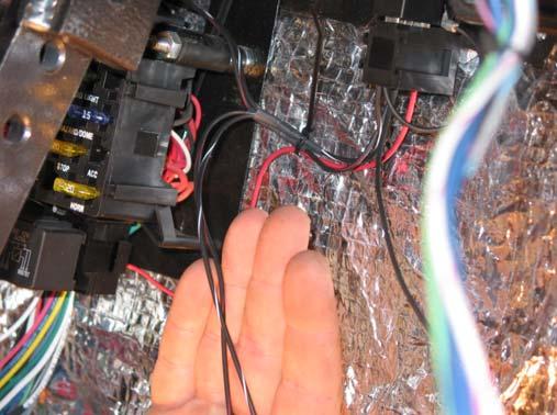
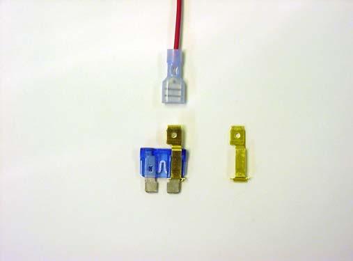
1 2501 Ludelle Street Fort Worth, Texas Phone Fax Sales Tech Web: Magnetic Door Jamb Switches (Ground Style) Installation Instructions This kit is designed to provide dome light door jamb switches without scratching the door jamb paint and to provide for a variety of door to jamb clearances. The kit will provide a ground signal to the dome light ground circuit through a relay using two magnetically actuated switches. The kit contains two separate switches and magnets for the driver s side door, the passenger s side door as well as the relay, wiring and small parts for the installation. Installation: All wires may be shortened before being attached to their destination for proper routing and looks. 1 Find a suitable location near the vehicles fuse block to mount the pre-wired relay base assembly. Using the furnished self tapping screw and star washer, insert the screw through the star washer, then the preinstalled ring terminal and mount the relay base. Make sure the area it s mounted to is part of the chassis ground. (Photo 1). 2 Once mounted, install the relay into the base. (Photo 2) 3 Locate a constant hot power source. (Photo 3) Note: It is recommended to disconnect the vehicle s negative battery cable from this step on, until this installation is complete. 4 Connect the red wire marked To Constant 12V Power Source using the T-Tap and male spade terminal (Photo 4) or the fuse tap terminal and female spade terminal. (Photo 5) 5 Route one black/white wire and one red/black wire to each side of the vehicle where the switches will be installed. There are two long and two short of each color according to the length needed. (Photo 6) doc
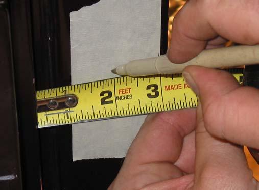
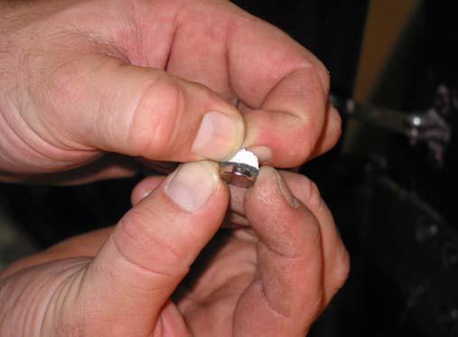
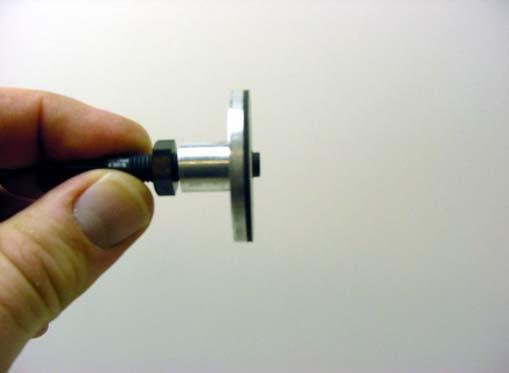
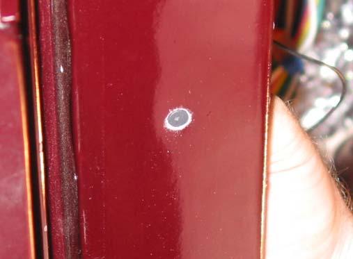
2 6 Locate a smooth, clean and flat surface on the backside of the door jambs on the vehicle. This is where the door jamb switch bushings will be mounted. 7 On the painted area opposite the smooth, clean, flat surface place a 4 piece of masking tape. (Photo 7) 8 Close the door and make a mark on both the door jamb and the door; at the approximate distance up the door to mount the magnets. (Photo 8) 9 With the door still closed, draw a line along the inner edge of the door on the masking tape. This line will be perpendicular to the lines drawn in step 8. (Photo 9) 10 Open the door. Peel the adhesive backing from the magnet and firmly press it onto the door. Be sure to keep the magnet inline with the two marks from step 8. (Photo 10) 11 From the inside edge of the door, measure to the middle of the magnet. (Photo 11) 12 Now measure the same distance from the perpendicular line on the masking tape and make a mark on the masking tape in the door jamb. Be sure the mark is in-line with the marks on the door jamb and the door. (Photo 12) 13 Using a center punch, punch the mark on the masking tape and drill a ¼ hole. (Photo 13) 14 With the moist towelettes provided, wipe off the flat surface on the backside of the door jamb around the hole. Be sure to allow enough time for the cleaner to evaporate to prevent diluting the adhesive on the bushing. (Photo 14) 15 Next, thread the aluminum bushing onto the black reed switch, until the end of the reed switch sticks out approximately the thickness of the metal on the door jamb. This adjustment can be made more accurately after the bushing is pressed onto the back of the door jamb. (Photos 15 &16) 16 Peel the adhesive backing from the aluminum bushing, use the part of the reed switch sticking out of the bushing to align it with the hole and press it onto the back of the door jamb firmly. Now readjust the reed switch and carefully tighten the jam nut. (Photos 17 & 18) 17 Using the provided red connectors, splice together the wires from the relay (the ones routed in step 5) to the wires on the door jamb switches. (Photos 19 & 20) 18 The final step in completing the installation is to connect the solid black wire from the relay base with <TO DOME LIGHT GROUND CIRCUIT> printed on it, to the part of the vehicles main harness, which provides ground to all of the interior lights doc


3 Photo #1 Photo #2 Photo #3 Photo #4 Photo #5 Photo # doc


4 Photo #7 Photo #8 Photo #9 Photo #10 Photo #11 Photo # doc


5 Photo #13 Photo #14 Photo #15 Photo #16 Photo #17 Photo # doc


6 Photo #19 Photo # doc
7 Painless Performance Limited Warranty And Return Policy Chassis harnesses and fuel injection harnesses are covered under a lifetime warranty. All other products manufactured and/or sold by Painless Performance are warranted to the original purchaser to be free from defects in material and workmanship under normal use. Painless Performance will repair or replace defective products without charge during the first 12 months from the purchase date. No products will be considered for warranty without a copy of the purchase receipt showing the sellers name, address and date of purchase. You must return the product to the dealer you purchased it from to initiate warranty procedures. Copyright 2007 by Perfect Performance Products, LLC 7
30107 & PACK & 6-PACK RELAY BANK
 30107 & 30108 2501 Ludelle Street Fort Worth, Texas 76105 817-244-6212 Phone 817-244-4024 Fax 888-350-6588 Sales 800-423-9696 Tech E-mail: painless@painlessperformance.com Web: www.painlessperformance.com
200-4R TRANSMISSION LOCK-UP HARNESS INSTALLATION INSTRUCTIONS
 2501 Ludelle Street Fort Worth, Texas 76105 817-244-6212 Phone 817-244-4024 Fax 888-350-6588 Sales 800-423-9696 Tech E-mail: painless@painlessperformance.com Web: www.painlessperformance.com 60110 200-4R
Installation Instructions For 50340
 Installation Instructions For 50340 2501 Ludelle Street Fort Worth, Texas 76105 817-244-6212 Phone 817-244-4024 Fax 888-350-6588 Sales 800-423-9696 Tech E-mail: painless@painlessperformance.com Web: www.painlessperformance.com
Installation Instructions For 50330, 50331, 50332, and Off Road Switch Panels
 Installation Instructions For 50330, 50331, 50332, and 50333 Off Road Switch Panels 2501 Ludelle Street Fort Worth, Texas 76105 817-244-6212 Phone 817-244-4024 Fax 888-350-6588 Sales 800-423-9696 Tech
PIN BULKHEAD CONNECTOR KIT
 2501 Ludelle Street Fort Worth, Texas 76105 817-244-6212 Phone 817-244-4024 Fax 888-350-6588 Sales 800-423-9696 Tech E-mail: painless@painlessperformance.com Web: www.painlessperformance.com 40130 22 PIN
Installation Instructions For #64260 Striker FE Module GMC/Chevrolet Duramax LB7 Diesel Copyright
 Installation Instructions For #64260 Striker FE Module 2001-2004 GMC/Chevrolet Duramax LB7 Diesel 2 nd Edition August 2007 Copyright 2006 by Perfect Performance Products, LLC 2501 Ludelle Street Fort Worth,
Installation Instructions For #64160 Striker II Power Module GMC/Chevrolet Duramax LB7 Diesel Copyright
 Installation Instructions For #64160 Striker II Power Module 2001-2004 GMC/Chevrolet Duramax LB7 Diesel 2 nd Edition August 2007 Copyright 2006 by Perfect Performance Products, LLC 2501 Ludelle Street
Installation Instructions. Part #65100
 Installation Instructions Part #65100 Perfect Performance Products, LLC Painless Performance Products Division 2501 Ludelle Street Fort Worth, TX 76105-1036 800-423-9696 phone 817-244-4024 fax Web Site:
20 CIRCUIT ATO FUSE CENTER INSTALLATION INSTRUCTIONS
 2501 Ludelle Street Fort Worth, Texas 76105 817-244-6212 phone 817-244-4024 fax 800-423-9696 Tech E-Mail: painless@painlessperformance.com Web: www.painlessperformance.com 30003 20 CIRCUIT ATO FUSE CENTER
Trail Rocker Installation Instructions
 Trail Rocker Installation Instructions Trail Rocker - Genesis Bracket For Installing Painless Part Number: 57200 Manual # 90591 To be used with Painless Kit # s: 57000-57005 Painless Performance Products
Off-Road Switch Panel Installation Instructions
 Off-Road Switch Panel Installation Instructions 50330: Off-road 4 Toggle switches/dash Mount w/keyed Ignition Switch 50332: Off-road 6 Toggle switches/dash Mount w/keyed Ignition Switch Painless Performance
Track Rocker Installation Instructions
 Track Rocker Installation Instructions For Installing Painless Part Numbers: 58103: 8-Switch Customizable Track Rocker Switch Panel w/ Flanged Mount 58106: 6-Switch Customizable Track Rocker Switch Panel
Wire Harness Installation Instructions
 Wire Harness Installation Instructions For Installing: Part #50001 Race Car Kit/8 Circuit Part #50201 8 Switch Dash Mounted Panel Part #50202 8 Switch Roll Bar Mounted Panel Manual #90502 Painless Performance
Trail Rocker Installation Instructions
 Trail Rocker Installation Instructions Manual #90580 For Installing Painless Part Numbers: 57000 and 57001 Painless Performance Products recommends you, the installer, read this installation manual from
Installation Instructions
 Installation Instructions Part #40120 Perfect Performance Products, LLC Painless Performance Products Division 2501 Ludelle Street Fort Worth, TX 76105-1036 800-423-9696 phone 817-244-4024 fax Web Site:
Trail Rocker Installation
 Trail Rocker Installation Instructions Customizable Trail Rocker Control System For Installing Painless Part Number: 57100 Manual #90616 Painless Performance Products recommends you, the installer, read
Trail Rocker Installation Instructions
 Trail Rocker Installation Instructions Manual #90581 For Installing Painless Part Numbers: 57002 Painless Performance Products recommends you, the installer, read this installation manual from front to
Installation Instructions For #64060 Striker I Power Module GMC/Chevrolet Duramax LB7 Diesel
 2501 Ludelle Street Fort Worth, Texas 76105 817-244-6212 Phone 817-244-4024 Fax 888-350-6588 Sales 800-423-9696 Tech E-mail: painless@painlessperformance.com Web: www.painlessperformance.com Installation
Installation Instructions For #64320 Striker Turbo Timer Module
 2501 Ludelle Street Fort Worth, Texas 76105 817-244-6212 Phone 817-244-4024 Fax 888-350-6588 Sales 800-423-9696 Tech E-mail: painless@painlessperformance.com Web: www.painlessperformance.com Installation
Trail Rocker Installation
 Trail Rocker Installation Instructions 4, 6, or 8 - Switch Customizable Trail Rocker Switch Panel w/ Flanged Mount For Installing Painless Part Number: 57103, 57106, & 57109 Manual #90636 Painless Performance
Installation Instructions For #64066 Striker I Power Module Ford Powerstroke 6.0L Diesel Copyright
 Installation Instructions For #64066 Striker I Power Module 2003-2006 Ford Powerstroke 6.0L Diesel 2 nd Edition August 2007 Copyright 2006 by Perfect Performance Products, LLC 2501 Ludelle Street Fort
Track Rocker Installation Instructions
 Track Rocker Installation Instructions Customizable Track Rocker Control System For Installing Painless Part Number: 58100 Track Rocker Relay Center Manual #90641 Painless Performance Products recommends
PERFECT HI-VELOCITY 62MM THROTTLE BODY
 PERFECT HI-VELOCITY 62MM THROTTLE BODY Installation Instructions Part # 65300 1991-1998 Jeep 4.0L Engines OR All Jeep 4.0L Engines in Cherokee, Grand Cherokee and Wrangler 1991-2005 w/4 wire IAC ONLY.
Perfect Performance Products, LLC Painless Performance Products Division 2501 Ludelle St. Fort Worth, Texas (800)
") PERFECT HI-VELOCITY 62MM THROTTLE BODY Installation Instructions Part # 65302 2005-2006 Jeep 4.0L All Jeep 4.0L Engines in Cherokee, Grand Cherokee, Wrangler and Rubicon. Perfect Performance Products,
PERFECT HI-VELOCITY 62MM THROTTLE BODY Installation Instructions Part # 65302 2005-2006 Jeep 4.0L All Jeep 4.0L Engines in Cherokee, Grand Cherokee, Wrangler and Rubicon. Perfect Performance Products,
Perfect Performance Products, LLC Painless Performance Products Division 2501 Ludelle St. Fort Worth, Texas (800)
") PERFECT HI-VELOCITY 68MM THROTTLE BODY Installation Instructions Part # 65301 1991-1998 Jeep 4.0L Engines w/perfect Engine Management System P/N 65140, 65141 OR All Jeep 4.0L Engines in Cherokee, Grand
PERFECT HI-VELOCITY 68MM THROTTLE BODY Installation Instructions Part # 65301 1991-1998 Jeep 4.0L Engines w/perfect Engine Management System P/N 65140, 65141 OR All Jeep 4.0L Engines in Cherokee, Grand
Part # GM LS2, 3 & 7-95mm Throttle Body
 Part # 65303 2006-2011 GM LS2, 3 & 7-95mm Throttle Body Perfect Performance Products, LLC 2501 Ludelle St. Fort Worth, Texas 76105 (800) 423-9696 1 We are always concerned about any corrections or improvements
30140 F5 Dual Fan Controller
 30140 F5 Dual Fan Controller 1 2501 Ludelle Street Fort Worth, Texas 76105 817-244-6212 Phone 817-244-4024 Fax 888-350-6588 Sales 800-423-9696 Tech E-mail: painless@painlessperformance.com Web: www.painlessperformance.com
Installation Instructions For #65000 Striker Cold Shot Gasoline 1 st Edition August 2007 Copyright 2007 by Perfect Performance Products, LLC 1
 2501 Ludelle Street Fort Worth, Texas 76105 817-244-6212 Phone 817-244-4024 Fax 888-350-6588 Sales 800-423-9696 Tech E-mail: painless@painlessperformance.com Web: www.painlessperformance.com Installation
Installation Instructions For #65003 Striker Cold Shot II 1 st Edition March 2009 Copyright 2009 by Perfect Performance Products, LLC 1
 2501 Ludelle Street Fort Worth, Texas 76105 817-244-6212 Phone 817-244-4024 Fax 888-350-6588 Sales 800-423-9696 Tech E-mail: painless@painlessperformance.com Web: www.painlessperformance.com Installation
INSTALLATION INSTRUCTIONS
 THANK YOU FOR CHOOSING KURYAKYN! Protect yourself and others from possible injury and property damage or loss. Pay close attention to all instructions, warnings, cautions, and notices regarding the installation,
TOYOTA YARIS HATCHBACK INTERIOR LIGHT UPGRADE Preparation
 Preparation Part Number PTS21-52062-08 NOTE: Part number of this accessory may not be the same as the part number show Kit Contents Item # Quantity Reqd. Description 1 1 12 Light Guide 2 1 7 Light Guide
Installation Instructions For #65005 Striker Cold Shot II 1 st Edition March 2009 Copyright 2009 by Perfect Performance Products, LLC
 2501 Ludelle Street Fort Worth, Texas 76105 817-244-6212 Phone 817-244-4024 Fax 888-350-6588 Sales 800-423-9696 Tech E-mail: painless@painlessperformance.com Web: www.painlessperformance.com Installation
Turn Signal Kit Installation Instructions for Model A Fords & Other Antique Vehicles
 Turn Signal Kit Installation Instructions for Model A Fords & Other Antique Vehicles Lifetime Technical Support support@logolites.com 770-476-7322 www.logolites.com Manual 100-0005N Thank you for purchasing
6945 (12v) 6944 (24V) installation instructions
 6944 (24V) installation instructions") 6945 (12v) 6944 (24V) installation instructions included: tools needed: Cordless drill Breezeeasy Fan Mounting brackets 1/4 Drill Bit 10mm Socket Hardware Pack 10mm Wrench Fuse Assembly Wire Stripper Crimper
6945 (12v) 6944 (24V) installation instructions included: tools needed: Cordless drill Breezeeasy Fan Mounting brackets 1/4 Drill Bit 10mm Socket Hardware Pack 10mm Wrench Fuse Assembly Wire Stripper Crimper
Line Lock Package, Mustang GT/GT500, 2007 PACKING LIST
 PART #M25002 Line Lock Package, Mustang GT/GT500, 2007 PACKING LIST Before installation, use this check list to make sure all necessary parts have been included. ITEM QTY CHECK PART NUMBER DESCRIPTION
USB Charge Port Installation Instructions
 USB Charge Port Installation Instructions Lifetime Technical Support support@logolites.com 770-476-7322 www.logolites.com Manual 100-0014C Thank you for purchasing a Logo Lites USB Charge Port! USB Charge
FUSION Model # - L-4910 L Fusion 49 and 60 Light Bar Instruction Manual V.1. This instruction manual serves as a guide for the Fusion Lightbar.
 Fusion 49 and 60 Light Bar Instruction Manual V.1 49 60 FUSION Model # - L-4910 L-6010 This instruction manual serves as a guide for the Fusion Lightbar. IMPORTANT! Please read through all provided instructions
YARIS 4-DOOR 2007 INTERIOR LIGHT UPGRADE
 Document # 3999 4/26/06 4-DOOR 2007 INTERIOR LIGHT UPGRADE Preparation Part Number: 00016-52060 Code: IL1 Kit Contents Item # Quantity Reqd. Description 1 1 12 Light Guide 2 1 7 Light Guide 3 1 Hardware
FUSION Model # - L-4910 L Fusion 49 and 60 Light Bar Instruction Manual V2.0. This instruction manual serves as a guide for the Fusion Lightbar.
 FENIEX. 2016 INSTRUCTION MANUAL Fusion 49 and 60 Light Bar Instruction Manual 49 60 FUSION Model # - L-4910 L-6010 This instruction manual serves as a guide for the Fusion Lightbar. IMPORTANT! Please read
Installation Instructions For #63021 Striker Diesel MD Power Modules Dodge 600/610 Cummins 5.9L Diesel Copyright
 2501 Ludelle Street Fort Worth, Texas 76105 817-244-6212 Phone 817-244-4024 Fax 888-350-6588 Sales 800-423-9696 Tech E-mail: painless@painlessperformance.com Web: www.painlessperformance.com Installation
30140 &30142 F5 Dual Fan Controller
 2501 Ludelle Street Fort Worth, Texas 76105 817-244-6212 Phone 817-244-4024 Fax 888-350-6588 Sales 800-423-9696 Tech E-mail: painless@painlessperformance.com Web: www.painlessperformance.com 30140 &30142
INSTALLATION INSTRUCTIONS
 THANK YOU FOR CHOOSING KURYAKYN! Protect yourself and others from possible injury and property damage or loss. Pay close attention to all instructions, warnings, cautions, and notices regarding the installation,
Light Duty Electronic Air Command
 2491 PSI BAR Light Duty Electronic Air Command INSTALLATION INSTRUCTIONS Congratulations on your purchase of a Light Duty Electronic Air Command kit. This kit was designed to provide inflation control
INSTALLATION CLAMP-ON FORK MOUNTED DRIVING LIGHTS 5015
 CLAMP-ON 5015 PARTS INCLUDED 2 Driving Lights 2 Side Mount Clamps-43mm/49mm 1 Hardware Kit Including: 2 49mm Spacers 4 43mm Spacers 2 Pivot Dome Washers 2 3/8-16 Serrated Hex Nut 1 Wiring Kit for Driving
Part Number: TBL-016S
 5/18/17 TOYOTA TUNDRA 2014-2017 LED Truck Bed Light Kit Part Number: TBL-016S Kit Contents Item # Quantity Reqd. Description 1 2 LED Bed Light Harness (10 ) 2 2 LED Bed Light Harness (5 ) 3 1 Y Harness
SOLAR BOLT CHARGING SYSTEM INSTALLATION GUIDE
 CHARGING SYSTEM Doc 1.00 INST052 1 SOLAR BOLT CHARGING SYSTEM CONTENTS General Information... 2 Solar Panel Installation... 3 Solar Bolt Main Harness and Indicate Installation... 4 Cable Routing... 9 Solar
SCION xd INTERIOR LIGHTING UPGRADE Preparation
 Preparation Part Number: PTS21-52085 Light Guide Kit Contents Item # Quantity Reqd. Description 1 1 Controller Board, 4 color programmed w/ Bracket 2 1 RGB, LED Engine wire harness 3 2 14mm Light Rod,
Plus SABRE LIGHTBARS
 INSTALLATION AND INSTRUCTION MANUAL Plus SABRE LIGHTBARS Models 5364LED, 5462LED, 5464LED and 5564LED PLIT445 REV. D 2/2/18 Keep any radio frequency sensitive equipment at least 20 from the bar and power
AC 110V POWER OUTLET INSTALLATION INSTRUCTIONS. Part No. Application 1. PRE INSTALLATION / INSTALLATION OVERVIEW 2. KIT CONTENTS H7110AJ100
 Part. Application H70AJ00 LEGACY / OUTBACK 0MY w/ HK audio LEGACY / OUTBACK 0MY w/o HK audio AC 0V POWER OUTLET INSTALLATION INSTRUCTIONS Page. -6,9-5 Page. -4,7-5. PRE INSTALLATION / INSTALLATION OVERVIEW
INSTALLATION CONSTELLATION DRIVING LIGHTS 5009
 INSTALLATION CONSTELLATION DRIVING LIGHTS 5009 PARTS INCLUDED 1 Right Driving Light with Turn Signals 1 Left Driving Light with Turn Signals 1 Installation Component Kit Including: 8 Insulated Male Spades
Xtreme Air Command. Step 1 Prepare the components. Step 2 Select a mounting location. Parts list
 2549 60 90 400 600 30 200 120 800 psi 1000 kpa PSI 0 150 Xtreme Air Command Installation instructions Congratulations on your purchase of a new Xtreme Air Command kit. This kit was designed to provide
Part Number: TBL-016S
 5/18/17 TOYOTA TACOMA 2016-2017 LED Bed Light Kit Part Number: TBL-016S Kit Contents Item # Quantity Reqd. Description 1 2 LED Bed Light Harness (10 ) 2 2 LED Bed Light Harness (5 ) 3 1 Y Harness Extension
Mounting brackets may vary depending on kit for vehicle year/model.
 Wiring Instructions ATTE: Before beginning any installation procedure, read all instructions carefully. Before drilling any holes make sure there is sufficient clearance on both sides. Retractable Running
Self-Deploying Rail Kit OEM INSTALLATION MANUAL
 Self-Deploying Rail Kit OEM INSTLLTION MNUL TLE OF ONTENTS Introduction 2 Safety Information 2 Resources Required 3 Prior to Installation 3 Installation 3 Doorjamb 3 Setting the Doorjamb 3 inch Latch 4
Fusion GPL 49 Instruction Manual
 FENIEX. 2018 INSTRUCTION MANUAL Fusion GPL 49 Instruction Manual 49 This instruction manual serves as a guide for the Fusion 49 GPL. Model # FN-4916 IMPORTANT! Please read through all provided instructions
INSTALLATION CONSTELLATION DRIVING LIGHTS 5009
 INSTALLATION CONSTELLATION DRIVING LIGHTS 5009 PARTS INCLUDED 1 Right Driving Light with Turn Signals 1 Left Driving Light with Turn Signals 1 Installation Component Kit Including: 8 Insulated Male Spades
Model RP310 Owner's Manual & Installation Instructions
 INSTALLATION AND INSTRUCTION MANUAL REMOTE STROBE PACK Model RP310 Owner's Manual & Installation Instructions PLITSTR223 REV. B 3/3/11 Table of Contents SAFETY WARNINGS 1 MOUNTING 2 WIRING INSTRUCTIONS
INSTALLATION MANUAL STEP SLIDER BD-SS-200-JK4. Made in the USA. Front Bracket Middle Bracket Rear Bracket. Tools Required
 Made in the USA INSTALLATION MANUAL STEP SLIDER BD-SS-200-JK4 Description Quantity Electric Step Slider (Pair) 2 Front Bracket Middle Bracket Rear Bracket Bump stop plate with VHB backing 2 Wiring harness
150 PSI ILLUMINATED DASH PANEL GAUGE KIT
 150 PSI ILLUMINATED DASH PANEL GAUGE KIT PART NO. 10061 (For Use with 20/30 Amp Systems) PART NO. 20062 (For Use with 30/40 Amp Systems) IMPORTANT: It is essential that you and any other operator of this
INSTALLATION INSTRUCTIONS
 THANK YOU FOR CHOOSING KURYAKYN! Protect yourself and others from possible injury and property damage or loss. Pay close attention to all instructions, warnings, cautions, and notices regarding the installation,
GENUINE PARTS INSTALLATION INSTRUCTIONS
 GENUINE PARTS INSTALLATION INSTRUCTIONS DESCRIPTION: APPLICATION: PART NUMBER: KIT CONTENTS: Illuminated Kick Plate Maxima (Applicable ONLY to U.S. Market Vehicles with Build Date June 2012 or later) 999G6
IMPORTANT OWNER-OPERATOR INSTALLATION INSTRUCTIONS A7710R / A7710RS
 IMPORTANT OWNER-OPERATOR INSTALLATION INSTRUCTIONS A7710R / A7710RS Warning!! This battery box is made of aluminum and is Conductive! Do not allow the battery terminals to touch the aluminum Battery Box.
INSTALLATION. DRIVING LIGHTS for FLHT/FLHX/FLHR BLACK. THANK YOU FOR CHOOSING KϋRYAKYN!
 THANK YOU FOR CHOOSING KϋRYAKYN! PROTECT YOURSELF AND OTHERS FROM POSSIBLE INJURY AND PROPERTY DAMAGE OR LOSS. PAY CLOSE ATTENTION TO ALL INSTRUCTIONS, WARNINGS, CAUTIONS, AND NOTICES REGARDING THE, USE,
HP10134 & HP10135 KITS BASIC SIMULTANEOUS AIR SPRING ACTIVATION KIT
 HP10134 & HP10135 KITS BASIC SIMULTANEOUS AIR SPRING ACTIVATION KIT Thank you and congratulations on the purchase of a Pacbrake simultaneous air spring activation kit. This kit was designed to add in-cab
Chrysler 45RFE Tailmount Automatic Transmission Shifter Installation Instructions
 Chrysler 45RFE Tailmount Automatic Transmission Installation Instructions Building American Quality With A Lifetime Warranty! TOLL FREE 1-877-469-7440 tech@lokar.com www.lokar.com Chrysler 45RFE Tailmount
4200 & 6200 Owner s Manual & Parts Book
 00 & 00 Owner s Manual & Parts Book Purchase Date Serial Number Model Number Tractor Model PN: - Dealer Date --0 Description Page To The Owner & Maintenance Safety Precautions & Torque Specifications Skid
Installation Instructions #63000 Striker Diesel MD Power Module Chevrolet Duramax 6.6L Diesel
 2501 Ludelle Street Fort Worth, Texas 76105 817-244-6212 Phone 817-244-4024 Fax 888-350-6588 Sales 800-423-9696 Tech E-mail: painless@painlessperformance.com Web: www.painlessperformance.com Installation
COBRA Model # - D X, D X, D-20109, D-20209, D-20409, D20609, D-20809, D-21015, D-20119, D Cobra Series- Instruction Manual V.
 V3.0 Cobra Series- Instruction Manual V.3 COBRA Model # - D-20109-1X, D-20215-2X, D-20109, D-20209, D-20409, D20609, D-20809, D-21015, D-20119, D-21109 This instruction manual serves as a guide for the
TOYOTA RAV4/HV INTERIOR LIGHT KIT Preparation
 Preparation Part Number: PT413-42130 Kit Contents Item # Quantity Reqd. Description 1 1 Wire Harness 2 3 Hardware Bag Contents Item # Quantity Reqd. Description 1 20 Cable Tie 2 2 Scotchlok 3 2 Foam Pad
MODEL NUMBER: MEDIUM DUTY ONBOARD AIR SYSTEM
 MODEL NUMBER: 10003 MEDIUM DUTY ONBOARD AIR SYSTEM IMPORTANT: It is essential that you and any other operator of this product read and understand the contents of this manual before installing and using
TJ YJ LJ STEP SLIDER INSTALLATION
 TJ YJ LJ STEP SLIDER INSTALLATION BD-SS-100-TJ, BD-SS-100-YJ, BD-SS-100-LJ PARTS LIST QTY DESCRIPTION 1 Drivers Side Slider Assembly 1 Passenger Side Slider Assembly 1 Wiring Harness 1 Double Sided Sticky
Section II - Installation Procedures Part Number : Accessory Code IL1 Kit Contents. Color Applicability/Trim Level. Hardware Bag Contents
 Document # 10.21.00 PIO/DIO 01/14/09 TOYOTA Rav-4 2009- INTERIOR InteriorLIGHT Light UPGRADE Upgrade Part Number : 00016-00065 Accessory Code IL1 Kit Contents Color Applicability/Trim Level Item # Quantity
SHAVED-DX. Installation Manual & Operation Instructions. Trouble Shooting Reverse Polarity Wiring Problems
 Trouble Shooting Reverse Polarity Wiring Problems Switch doesn't work properly but the shaved kit transmitters do work Step 1 Did you purchase a switch kit designed for three switches and only use two
Seatbelt Solutions
 Seatbelt Solutions www.seatbeltsolutions.com 3-Point Conversion Seatbelt Installation Guide for: 1947-1967 Trucks Seatbelt Solutions 90 Degree Bracket 7/16 Stud Plate 1 1/2 x 7/16 x20 Bolts Pop Rivets
Wiper Motor Windshield Frame Mount Marinco-500. Installation Instructions
 Wiper Motor Windshield Frame Mount Marinco-500 Installation Instructions Wiper Motor Windshield Frame Mount Marinco-500 Tools (Not Included): Phillips head screwdriver 17 mm or small adjustable wrench
RIVA YAMAHA GPR MECHANICAL TRIM-TAB SYSTEM PART # (RY2820) APPLICATIONS: GP1200R GP800R NOTICE :
 APPLICATIONS: GP1200R GP800R NOTICE :") RIVA YAMAHA GPR MECHANICAL TRIM-TAB SYSTEM PART # (RY80) APPLICATIONS: 000-00 GP00R 00-00 GP800R NOTICE : This system has been upgraded with a new heavy-duty pivot rod that features welded on push rod
RIVA YAMAHA GPR MECHANICAL TRIM-TAB SYSTEM PART # (RY80) APPLICATIONS: 000-00 GP00R 00-00 GP800R NOTICE : This system has been upgraded with a new heavy-duty pivot rod that features welded on push rod
INSTALLATION INSTRUCTIONS
 REV 3 05/13/2016 INSTALLATION INSTRUCTIONS PART NO. 960001T 960003T PRODUCT DESCRIPTION: Full size Powered Light Bar Mid size Powered Light Bar Sport Bar and lights sold separately shown for reference
CRYSTEEL S. this manual must be included with the vehicle after completing the installation.
 Website: www.tbei.com E-mail: sales@tbei.com CRYSTEEL S POWER TAILGATE this manual must be included with the vehicle after completing the installation. Web Site E-Mail Phone (507) 726-2728 www.crysteel.com
MSD SB6 Programmable Ignition for the Kawasaki ZX-14 PN 4219
 INSTALLATION INSTRUCTIONS MSD SB6 Programmable Ignition for the Kawasaki ZX-14 PN 4219 Parts Included: 1 - Ignition 1 - Wiring Harness 1 - Parts Bag 1 - CD ROM WARNING: When installing the SB6, disconnect
INSTALLATION INSTRUCTIONS
 INSTALLATION INSTRUCTIONS PARTS LIST Accessory Application Publications No. MII 13038 GL1800 P/N 08E75-MCA-100K Issue Date November 2009 Honda Dealer: Please give a copy of these instructions to your customer.
GENUINE PARTS INSTALLATION INSTRUCTIONS
 GENUINE PARTS INSTALLATION INSTRUCTIONS 1. 2. 3. 4. DESCRIPTION: Security Light Kit APPLICATION: Altima Coupe and Sedan (2011+) PART NUMBER: 999F4 AX008 - Universal Security Lighting Kit. KIT CONTENTS:
ONBOARD AIR HOOKUP KIT
 ONBOARD AIR HOOKUP KIT PART NO. 20052 (30 amp - 110PSI on, 150PSI off) PART NO. 20053 (30 amp - 85PSI on, 105 PSI off) PART NO. 20055 (30 amp - 90 PSI on, 120 PSI off) IMPORTANT: It is essential that you
Instruction Manual Includes:
 Instruction Manual Includes: Page 1: HydraHorse Installation for Basic 2- Horse System Part I: Tank, pump, and electrical supply Page 6: Page 9: Part II: Page Bowls, Brackets, Pipes and Fittings Installing
CHEVY CAMARO Four panel Sequential LED Taillight kit installation guide
 1978-81 CHEVY CAMARO Four panel Sequential LED Taillight kit installation guide Kit Contents: 4 LED panels 1 power wire with t-tap 2 driver side LED harnesses, 24 2 passenger side LED harnesses, 48 4 LED
ROADMASTER, Inc NE 127th Ave. Vancouver, WA Fax roadmasterinc.com ROADMASTER, Inc.
 ROADMASTER, Inc. 6110 NE 127th Ave. Vancouver, WA 98682 800-669-9690 Fax 360-735-9300 roadmasterinc.com 2008-2017 ROADMASTER, Inc. All rights reserved. 853600-05 11/17 Read all instructions before installing
INSTALLATION INSTRUCTIONS
 THANK YOU FOR CHOOSING KURYAKYN! Protect yourself and others from possible injury and property damage or loss. Pay close attention to all instructions, warnings, cautions, and notices regarding the installation,
TOYOTA RAV TVIP V3
 Section I Installation Preparation Part Number: 08586-4A872 Section I Installation Preparation Kit Contents Item # Quantity Reqd. Description 1 1 Wire Harness 2 1 Status Monitor 3 1 Piezo Buzzer 4 1 V3
TOYOTA im INTERIOR LIGHT KIT Preparation
 Preparation Part Number: PT922-12170 Kit Contents Item # Quantity Reqd. Description 1 1 Main Wire Harness 2 1 Switch 3 1 Switch Header 4 1 ECU 5 1 ECU Bracket 6 1 Hardware Kit 7 1 Instruction Card 8 1
Installation Instructions YJ Hardtop
 INSTALLATION TIME Installation Instructions YJ Hardtop US Patents 6468149, 6309007, D442,911 SKILL LEVEL Application: 2 Piece without Doors Part Number: 41499 1 Piece without Doors Part Number: 41497 2
with installation boost GAUGE this manual is for use with systems
 owners manual with installation instructions dynafact boost GAUGE this manual is for use with systems 64050-64054 gale banks engineering 546 duggan avenue azusa, ca 91702 (626) 969-9600 www.bankspower.com
AIR CONTROL ACCESSORY KIT
 RAPID RESPONSE SYSTEM 2283 AIR CONTROL ACCESSORY KIT INSTALLATION INSTRUCTIONS Congratulations on your purchase of a new Air Control Accessory Kit. This kit was designed to provide inflation control of
INSTALLATION INSTRUCTIONS DOCUMENT REVISION : /17/2014
 INSTALLATION INSTRUCTIONS DOCUMENT REVISION : 1.0 10/17/2014 LPF COMPONENT LIST LPF W/ WIRE & GROMMET ( 1 ) M6 X 20MM SCREW ( 2 )* LPF DRIVER BOX ( 1 ) REVERSE CIRCUIT WIRE ( 1 ).25 THICK LICENSE PLATE
Hypertech In-line Speedometer Calibrator Module Installation Instructions PN Ford F150 and 2017 Ford F250
 Hypertech In-line Speedometer Calibrator Module Installation Instructions PN 730125 2017-2018 Ford F150 and 2017 Ford F250 This installation manual shows an example installation on a 2017 Ford F150 and
KT145 Series John Deere 6076 with Nippondenso Inj. Pump
 KT145 Series John Deere 6076 with Nippondenso Inj. Pump 30 Years Strong! Introduction The KT145 Series Governor System Installation Kit provides the necessary brackets and hardware to install a GAC precise
Rear Vision System Liftgate Emblem Camera for Aftermarket Display Ford Flex (Kit part number )
") Rear Vision System Liftgate Emblem Camera for Aftermarket Display 2009-2012 Ford Flex (Kit part number 1008-6509) Kit Contents: Liftgate Emblem Mount with Camera Chassis Harness with RCA (Note: In some
Rear Vision System Liftgate Emblem Camera for Aftermarket Display 2009-2012 Ford Flex (Kit part number 1008-6509) Kit Contents: Liftgate Emblem Mount with Camera Chassis Harness with RCA (Note: In some
Table of Contents Hydraulic Kit
 Personal Plow Hydraulic Kit Parts Lists and Diagrams January 5, 2004 Lit. No. 27564 Table of Contents Parts Box...2 Hose Routing...2 Ram Components... 3 Hydraulic Unit and Back-Up / O-Ring Kit Parts Lists...4
INSTALLATION LIGHTED CURVED LAY DOWN LICENSE PLATE MOUNT 3166
 INSTALLATION LIGHTED CURVED LAY DOWN LICENSE PLATE MOUNT 3166 PARTS INCLUDED 1 Lighted Curved Lay Down License Plate Assembly 1 Hardware Kit Including: 6 Cable Ties 1 Dielectric Grease Pack 1 1 x 8 Tape
PRODUCT/SERVICE BULLETIN. July 29, 1993 HWH Personnel, Distributors, Retailers and Installers Leroy Van Roekel Field Enhancement FIELD ENHANCEMENT
 HCORPORATIONH W R (On I-80, Exit 267 South) 2096 Moscow Road, Moscow, Iowa 52760 Phone: (800)321-3494 or (563)724-3396 Fax: (563)724-3408 Internet: www.hwhcorp.com ISSUE DATE: TO: FROM: RE: PRODUCT/SERVICE
INSTALLATION MANUAL. Level of Difficulty. Parts List. Product Image. Tools Required. Notes and Maintenance. Torque Specifications.
 INSTALLATION MANUAL Parts List 1 Bull bar 2 Upper frame mounting bracket 1 Driver / left lower frame mounting bracket 1 Passenger / right lower frame mounting bracket 2 Button head bolt, 6mm 4 Flat washer,
12 Volt Utility Controller for 4, 6, or 8 Brakes No
 12 Volt Utility Controller for 4, 6, or 8 Brakes No. 1300-76 P-1396-WE 819-0301 Installation Instructions An Altra Industrial Motion Company Contents Introduction... 2 Installation... 3 Mounting Under