TABLE OF CONTENTS TRUCK AIR SUSPENSIONS. No: PRIMAAX GEN II MAINTENANCE MANUAL. Subject: Date: NOVEMBER 2010 Revision: O
|
|
|
- Todd Watson
- 5 years ago
- Views:
Transcription
1 Refers to Products in the Asia Pacific Region Only TRUCK AIR SUSPENSIONS No: Subject: PRIMAAX GEN II MAINTENANCE MANUAL Date: NOVEMBER 2010 Revision: O TABLE OF CONTENTS SECTION 1 Introduction... 3 SECTION 2 Product Description... 4 SECTION 3 IMPORTANT SAFETY NOTICE... 5 SECTION 4 Parts List... 9 Parts Kit Listings SECTION 5 Tools SECTION 6 Preventative Maintenance Visual Inspection U Bolts Longitudinal and Transverse Torque Rods Shock Absorber Inspection Shock Absorber Visual Inspection Procedure SECTION 7 Alignment & Adjustments Ride Height Adjustment Lateral Alignment Rear Axle Alignment Pinion Angle Pinion Angle Adjustment Alignment Instructions SECTION 8 Component Replacement Fasteners Air Spring Height Control Valve Shock Absorbers Longitudinal Torque Rod Transverse Torque Rod Transverse Torque Rod Bushing Support Beam Assembly and Cross Tube D-Pin Bushing Quick-align Pivot Bushing Top Pad Bottom Cap Axle Bump Stops Frame Hanger SECTION 9 Plumbing Diagram SECTION 10 Torque Specifications SECTION 11 Trouble Shooting Guide of 39
2 Amendment Table Serial Revision - Date Page - Remarks Paragraph (a) (b) (c) (d) 1. Rev O 30 Nov 10 Page 1 Header Layout and Revision to O 2. Rev O 30 Nov 10 Page 2 Add: Amendment Table 3. Rev O 30 Nov 10 Page 10 Add Part Number: inch UNF Dacromet Hex Bolt inch UNF Dacromet Locknut 4 Page 11 Add Part Number: inch UNF Dacromet Hex Bolt inch UNF Dacromet Locknut Delete Part Number inch UNC Dacromet Hex Bolt inch UNC Dacromet Locknut 5. Rev O 30 Nov 10 Page 37 Add 1 inch -14 UNF Quick Align Torque 750 N.m 2 of 39

3 This publication is to acquaint and assist maintenance personnel in the preventative maintenance and rebuild of the PRIMAAX suspension system. NOTE: Use only Genuine Hendrickson parts for servicing this suspension system. Most Hendrickson parts can be identified by the Hendrickson trademark. It is important to read and understand the entire Technical Bulletin prior to performing any maintenance, service, repair, or rebuild of the product. The information in this publication contains parts lists, safety information, product specifications, features, maintenance, service, repair and rebuild instructions for the PRIMAAX Suspension. Hendrickson reserves the right to make changes and improvements to its products and publications at any time. Contact Hendrickson Tech Services at for information on the latest version of this manual or view the latest version online at Frame Hanger Clamp Group Main Beam Longitudinal Torque Rod Cross Tube 3 of 39
4 Figure 2-1 Reduced maintenance cost and increased uptime of your vehicle. No Lubrication requirements, heavy-duty rubber bushings used to improve service life Heavy Duty Torque Rods used for longer service life Large volume air springs incorporated to reduce noise, vibration and harshness to cab, chassis and body equipment for reduced total vehicle maintenance Proven Quick- Align Adjusters PAX 230 PAX 460 PAX 520 Capacity 10,500kg 18,000kg. 22,000kg. Axle Configuration. 1 Single Tandem Tandem GCM Approval. 2 80,000kg. 120,000kg. 140,000kg Axle Travel (mm) 150 (mm)m 150 (mm) Ground Clearance. 273 (mm) 273 (mm) 273 (mm) Ride Height (mm) (mm) (mm) Engine Restrictions. None None None PRIMAAX approved for vocational and heavy-haul vehicle applications including, but not limited to: Truck, Prime Mover, Tipper, Road Train, Agitator, Refuse, Logging, Fire/Rescue, Speciality and vehicles equipped with outriggers contact Hendrickson or original equipment manufacturer for additional applications and information. Patent pending 1. Installed weight includes complete suspension, torque rods, axle and frame brackets, and all hardware. Published weight is for standard PRIMAAX suspension. Other configurations may change weight. 2. Contact Hendrickson or vehicle manufacturer for applications that may exceed GVW/GCW approval ratings. 3. Axle travel may be limited by vehicle manufacturer; axle stop settings may restrict suspension s articulation. 4. For different options, please contact Hendrickson or Authorised OEM for further information. 4 of 39
5 Proper maintenance, service and repair are important to the reliable operation of the suspension. The procedures recommended by Hendrickson and described in this technical publication are methods of performing such maintenance, service and repair. The warnings and cautions should be read carefully to help prevent personal injury and to assure that proper methods are used. Improper maintenance, service or repair may cause personal injury, render the vehicle unsafe in operation, cause damage to the vehicle, or void manufacturer's warranty. Failure to follow the safety precautions in this manual can result in personal injury and/or property damage. Carefully read and understand all safety related information within this publication, on all decals and, that provided by the vehicle manufacturer before conducting any maintenance, service or repair. EXPLANATION OF SIGNAL WORDS Hazard Signal Words (Danger-Warning-Caution) appear in various locations throughout this publication. Information accented by one of these signal words must be observed to help minimise the risk of personal injury to service personnel, or possibility of improper service methods which may render it unsafe or damage the vehicle. This is the safety alert symbol. It is used to alert you to potential personal injury hazards. Obey all safety messages that follow this symbol to avoid possible injury or death. NOTE: SERVICE HINT: WARNING WARNING WARNING An operating procedure, practice condition, etc. which is essential to emphasise. A helpful suggestion which will make the servicing being performed a little easier and/or faster. Also note that particular service operations may require the use of special tools designed for specific purposes. FASTENERS LOOSE OR OVER TORQUED FASTENERS CAN CAUSE SEVERE PERSONAL INJURY, COMPONENT DAMAGE, LOSS OF VEHICLE CONTROL OR PROPERTY DAMAGE,. MAINTAIN CORRECT TORQUE VALUE AT ALL TIMES. CHECK TORQUE VALUES ON A REGULAR BASIS AS SPECIFIED, USING A TORQUE WRENCH THAT IS REGULARLY CALIBRATED. LOAD CAPACITY ADHERE TO THE PUBLISHED CAPACITY RATINGS FOR THE SUSPENSION. ADD-ON AXLE ATTACHMENTS AND OTHER LOAD TRANSFERRING DEVICES CAN INCREASE THE SUSPENSION LOAD ABOVE ITS RATED AND APPROVED CAPACITIES, WHICH CAN RESULT IN COMPONENT DAMAGE AND LOSS OF VEHICLE CONTROL, POSSIBLY CAUSING PERSONAL INJURY OR PROPERTY DAMAGE. MODIFYING COMPONENTS DO NOT MODIFY OR REWORK PARTS WITHOUT AUTHORISATION FROM HENDRICKSON. DO NOT SUBSTITUTE PARTS OF THE SUSPENSION. USE OF MODIFIED OR REPLACEMENT PARTS NOT AUTHORISED BY HENDRICKSON MAY NOT MEET HENDRICKSON'S SPECIFICATIONS, AND CAN RESULT IN COMPONENT DAMAGE, LOSS OF VEHICLE CONTROL, AND POSSIBLE PERSONAL INJURY OR PROPERTY DAMAGE. USE ONLY HENDRICKSON AUTHORISED REPLACEMENT PARTS. 5 of 39
6 WARNING WARNING WARNING WARNING WARNING WARNING CAUTION TORCH/WELDING DO NOT USE A CUTTING TORCH TO REMOVE ANY ATTACHING FASTENERS. THE USE OF HEAT ON SUSPENSION COMPONENTS MAY ADVERSELY AFFECT THE STRENGTH OF THESE PARTS. EXERCISE EXTREME CARE WHEN HANDLING OR PERFORMING MAINTENANCE IN THE AREA OF THE SUPPORT BEAM. DO NOT CONNECT ARC WELDING GROUND LINE TO THE SUPPORT BEAM. DO NOT STRIKE AN ARC WITH THE ELECTRODE ON THE SUPPORT BEAM AND AXLE. DO NOT USE HEAT NEAR THE SUPPORT BEAM ASSEMBLY. DO NOT NICK OR GOUGE THE SUPPORT BEAM. SUCH IMPROPER ACTIONS CAN DAMAGE THE SUPPORT BEAM. THE ASSEMBLY COULD FAIL, AND CAUSE POSSIBLE PERSONAL INJURY, LOSS OF VEHICLE CONTROL AND OR PROPERTY DAMAGE. WORK SITE DUMPING WHEN THE BED OF THE TRUCK/TRAILER IS TILTED, IT IS MANDATORY TO COMPLETELY EXHAUST THE AIR FROM THE SUSPENSION SYSTEM TO HELP PROVIDE STABILITY ON UNEVEN TERRAIN. FAILURE TO DO SO COULD RESULT IN LOSS OF VEHICLE CONTROL, POSSIBLY CAUSING PERSONAL INJURY OR PROPERTY DAMAGE. PROCEDURES AND TOOLS A TECHNICIAN USING A SERVICE PROCEDURE OR TOOL WHICH HAS NOT BEEN RECOMMENDED BY HENDRICKSON MUST FIRST SATISFY HIMSELF THAT NEITHER HIS SAFETY NOR THE VEHICLE'S SAFETY WILL BE JEOPARDISED BY THE METHOD OR TOOL SELECTED. INDIVIDUALS DEVIATING IN ANY MANNER FROM THE INSTRUCTIONS PROVIDED WILL ASSUME ALL RISKS OF CONSEQUENTIAL PERSONAL INJURY OR DAMAGE TO EQUIPMENT INVOLVED. SHOCK ABSORBERS THE SHOCK ABSORBERS ARE THE REBOUND TRAVEL STOPS FOR THE SUSPENSION. ANYTIME THE AXLE ON A PRIMAAX SUSPENSION IS SUSPENDED IT IS MANDATORY THAT THE SHOCK ABSORBERS REMAIN CONNECTED. FAILURE TO DO SO CAN CAUSE THE AIR SPRINGS TO SEPARATE FROM THE PISTON AND RESULT IN PREMATURE AIR SPRING FAILURE. REPLACEMENT OF SHOCK ABSORBERS WITH NON-HENDRICKSON PARTS CAN ALTER THE REBOUND TRAVEL OF THE SUSPENSION. PERSONAL PROTECTIVE EQUIPMENT ALWAYS WEAR PROPER EYE PROTECTION AND OTHER REQUIRED PERSONAL PROTECTIVE EQUIPMENT TO HELP PREVENT PERSONAL INJURY WHEN PERFORMING VEHICLE MAINTENANCE, REPAIR OR SERVICE. AIR SPRING INFLATION DO NOT INFLATE AIR SPRING ASSEMBLY WHEN IT IS UNRESTRICTED. ASSEMBLY MUST BE RESTRICTED BY THE SUSPENSION OR OTHER ADEQUATE STRUCTURE. DO NOT INFLATE BEYOND PRESSURES OF 690kPa AT DESIGN RIDE HEIGHT. CONTACT HENDRICKSON TECH SERVICES FOR DETAILS. IMPROPER USE OR OVER INFLATION CAN CAUSE ASSEMBLY TO BURST CAUSING SEVERE PERSONAL INJURY PROPERTY AND/OR COMPONENT DAMAGE. INFLATE THE SUSPENSION SLOWLY AND MAKE SURE THAT THE RUBBER BLADDER OF THE AIR SPRING INFLATES UNIFORMLY AND IS NOT BINDING. FAILURE TO DO CAN CAUSE DAMAGE TO THE UPPER AIR SPRING MOUNTING BRACKET AND VOID WARRANTY. 6 of 39
7 WARNING WARNING WARNING WARNING WARNING AIR SPRING DEFLATION AIR SPRINGS MUST BE DEFLATED PRIOR TO LOOSENING ANY CLAMP GROUP HARDWARE. UNCONSTRAINED AIR SPRINGS WILL VIOLENTLY SHIFT, RESULTING IN PERSONAL INJURY, DEATH OR PROPERTY DAMAGE. IF THE AIR SPRING IS BEING REMOVED, IT IS MANDATORY TO LUBRICATE THE LOWER AIR SPRING FASTENERS WITH PENETRATING OIL AND REMOVE WITH HAND TOOLS TO PREVENT DAMAGE TO THE LOWER AIR SPRING MOUNTING STUD. FAILURE TO DO SO CAN CAUSE COMPONENT DAMAGE AND VOID WARRANTY. PARTS CLEANING SOLVENT CLEANERS CAN BE FLAMMABLE, POISONOUS, AND CAUSE BURNS. TO HELP AVOID SERIOUS PERSONAL INJURY, CAREFULLY FOLLOW THE MANUFACTURER S PRODUCT INSTRUCTIONS AND GUIDELINES AND THE FOLLOWING PROCEDURES: 1. WEAR PROPER EYE PROTECTION. 2. WEAR CLOTHING THAT PROTECTS YOUR SKIN. 3. WORK IN A WELL-VENTILATED AREA. 4. DO NOT USE SOLVENTS THAT CONTAIN GASOLINE. GASOLINE CAN EXPLODE. 5. HOT SOLUTION TANKS OR ALKALINE SOLUTIONS MUST BE USED CORRECTLY. FOLLOW THE MANUFACTURER'S RECOMMENDED INSTRUCTIONS AND GUIDELINES CAREFULLY TO HELP PREVENT PERSONAL ACCIDENT OR INJURY. DO NOT USE HOT SOLUTION TANKS OR WATER AND ALKALINE SOLUTIONS TO CLEAN MACHINED OR POLISHED PARTS. DOING SO WILL CAUSE DAMAGE TO THE PARTS AND VOID WARRANTY. QUIK-ALIGN FASTENERS DO NOT ASSEMBLE QUIK-ALIGN JOINT WITHOUT THE PROPER FASTENERS. USE ONLY DACROMET PLUS XL PLATED FASTENERS TO SUSTAIN PROPER CLAMP FORCE. FAILURE TO DO SO CAN CAUSE LOSS OF VEHICLE CONTROL, PROPERTY DAMAGE OR PERSONAL INJURY. ENSURE THAT QUIK-ALIGN FASTENER TORQUE VALUES ARE SUSTAINED AS RECOMMENDED IN THE TORQUE REQUIREMENTS SECTION OF THIS PUBLICATION. FAILURE TO DO SO CAN CAUSE LOSS OF VEHICLE CONTROL RESULTING IN PERSONAL INJURY OR PROPERTY DAMAGE. SUPPORT BEAM AND CROSS TUBE ASSEMBLY DO NOT STRIKE SUSPENSION COMPONENTS WITH A HAMMER. HOWEVER, THE SUPPORT BEAM AND CROSS TUBE JOINT REQUIRES BLUNT FORCE ON THE SUPPORT BEAM AT THE JOINT TO DISLODGE THE TWO COMPONENTS. Do not strike the ALL BLUNT FORCE MUST BE APPLIED FLUSH TO support beam flanges nor jack the THE THICKEST PART OF THE SUPPORT BEAM AT vehicle from the THE INBOARD CORNER JOINT. FAILURE TO Support Beam STRIKE THE SUPPORT BEAM SQUARELY MAY RESULT IN COMPONENT DAMAGE, PREMATURE FAILURE AND VOID WARRANTY. CROSS TUBE ASSEMBLY IMPROPER JACKING METHODS CAN CAUSE STRUCTURAL DAMAGE AND RESULT IN LOSS OF VEHICLE CONTROL, SEVERE PERSONAL INJURY OR DEATH AND WILL VOID HENDRICKSON'S WARRANTY. DO NOT USE THE SUSPENSION SUPPORT BEAM OR THE CROSS TUBE AS A JACKING POINT. REFER TO VEHICLE MANUFACTURER FOR PROPER JACKING INSTRUCTIONS. 7 of 39


8 WARNING SAFETY DECALS REPLACE ANY SAFETY DECALS THAT ARE FADED, TORN, MISSING, ILLEGIBLE, OR OTHERWISE DAMAGED. CONTACT YOUR DEALER TO ORDER REPLACEMENT LABELS. Figure 3-2 Figure 3-3 IMPROPER JACKING Figure 3-4 PROPER JACKING AT THE DIFFERENTIAL ASSEMBLY 8 of 39


9 9 of 39
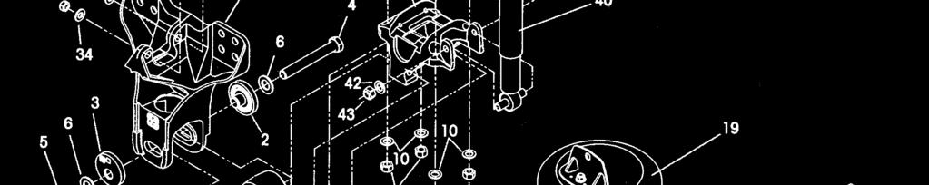
10 KEY NO.* DISCRIPTION QTY KEY NO.* DISCRIPTION QTY Frame Hanger [Cast] *** Bushing Straddle Bar ¾ holes Frame Hanger [Fab LH R02] *** L Torque Rod Bushing Frame Hanger [Fab RH R02] *** Hex Bolt Spacer 8mm R01 4 (M24 Bolt kit listed page 10) QUIK-ALIGN Concentric Base Locknut QUIK-ALIGN Eccentric Base Dacromet Flat Washer UNC-2A Dacromet Hex Bolt 4 (Superseded to /10/10) Hex Bolt Locknut UNF Dacromet Hex Bolt Flat Washer UNF Dacromet Locknut Shim 1.6 mm UNC-2B Dacromet Locknut 4 35a Shim 3.0 mm Dacromet Flat Washer 8 35b Shim 6.0 mm Extreme duty quick align bolt kit Refer to page 11 35c Shim 10.0 mm 7a Axle Cap 4 7b Axle Cap (520) Fab 7c Axle Cap (520) Fab 8 See next Page U Bolt Kit 9 U Bolt Locknut 10 U Bolt Flat Washer 11a Bottom Cap 3.5 Degree 4 11b Bottom Cap 12.0 Degree 4 11c Bottom Cap 2.0 Degree LH 1 11d Bottom Cap 2.0 Degree RH 11e Bottom Cap 10.0 Degree LH 11f Bottom Cap 10.0 Degree RH ¾ Flat Washer ¾ -16 UNF Locknut ¾ -16 UNF Bolt 8 15 Support Beam Assy (Includes Nos 16-& 17) Support Beam Assy LHF Support Beam Assy RHF Support Beam Assy LHR Support Beam Assy RHR QUIK-ALIGN Pivot Bushing D-Pin Bushing Cross Tube (864mm Chassis) Cross Tube (877mm Chassis) Cross Tube (870mm Chassis) Air Spring Assy Lower Air Spring Bracket ½ -13 UNC Locknut ½ Flat Washer End Cap /8 Dacromet Flat Washer **** 25 7/8 Hex Bolt **** 26 Longitudinal Torque Rod - Part of Kit No A Left front B Right Front A Left Rear B Right Rear Transverse Rod Assy L Bushing-Straddle Bar Pin Transverse Rod Frame Bracket Frame Mounted Axle Stop ** Shock Absorber (superseded to /2007) Shock Absorber H/duty (standard production as of 01/12/2007) Shock Upper Frame Bracket Flat Washer Locknut Bolt Flat Washer Locknut Bolt P Height Control Valve Height Control Valve Kit Rod HCV 375mm R Bracket HCV Lower Decal Road Friendly 1 *NOTE: This is a general parts listing to provide directional information. Components may vary. For questions, contact Hendrickson Asia Pacific Pty Ltd on ** NOTE: Item required, components supplied by Hendrickson or vehicle manufacturer. Hendrickson is not responsible for components not supplied by Hendrickson, for assistance with maintenance and / or rebuild of these components, see the vehicle manufacturer *** NOTE: Number of Items varies according to OEM and vehicle configurations, for assistance with these components, see the vehicle manufacturer 10 of 39
11 Parts Kit Listings Fastener Kit QUIK-ALIGN 1 axle Concentric Base Eccentric Base UNF Dacromet Hex Bolt UNF Dacromet Locknut Hardened Flat Washer Fastener Kit QUIK-ALIGN 2 axle Concentric Base Eccentric Base UNF Dacromet Hex Bolt UNF Dacromet Locknut Hardened Flat Washer Extreme Duty QUICK-ALIGN 1 axle Concentric Base 2 Eccentric Base 2 1 ¼ - 12UNF 8.0 Bolt 2 1 ¼ - 12 UNF Locknut 2 1 ¼ Hardened Washer Fastener Kit Shock Absorber 1 axle /4 Hardened Washer /4-10UNC Locknut /4-10UNC 4.25 Bolt /8 Hardened Washer /8-11UNC Hexbolt /8-11UNC Locknut Fastener Kit Shock Absorber 2 axle /4 Hardened Washer /4-10UNC Locknut /4-10UNC 4.25 Bolt /8 Hardened Washer /8-11UNC Hexbolt /8-11UNC Locknut End Cap KIT 1 axle /8 Hardened Washer /8-9UNC 3.50 Bolt End Cap End Cap KIT 2 axle /8 Hardened Washer /8-9UNC 3.50 Bolt End Cap Beam Centre Mounting Kit 1 axle /4 Hardened Washer /4-16UNF Locknut /4-16UNF 5.00 Bolt Beam Centre Mounting Kit 2 axle /4 Hardened Washer /4-16UNF Locknut /4-16UNF 5.00 Bolt U Bolt Assembly Kit 1 axle (230) /4 Hardened Washer /4-16UNF U-Bolt Locknut /4-16UNF 8.50 Sq U-Bolt U Bolt Assembly Kit 2 axle (460) /4 Hardened Washer /4-16UNF U-Bolt Locknut /4-16UNF 8.50 Sq U-Bolt U Bolt Assembly Kit 2 axle (520) /4 Hardened Washer /4-16UNF U-Bolt Locknut /4-16UNF 9.29 Sq U-Bolt Torque Rod Fastener Kit 1 axle /4 Hardened Washer /8 Hardened Washer /8-14UNF Locknut /8-16UNF Bolt /4-16UNF Locknut /4-16UNF 3.75 Bolt M24 Top Pad Fastener Kit 1 axle mm Hardened Washer mm nut mm Bolt Torque Rod Fastener Kit 2 axle /4 Hardened Washer /8 Hardened Washer /8-14UNF Locknut /8-14UNF Bolt /4-16UNF Locknut /4-16UNF 3.75 Bolt M24 Top Pad Fastener Kit 2 axle mm Hardened Washer mm nut mm Bolt P Air Spring Fastener Kit (2 per axle) /2 Hardened Washer /2-13UNC Nylock Nut Air Spring Fastener Kit 2 axle /2 Hardened Washer /2-13UNC Nyloc Nut 8 11 of 39
12 ! " " Part No: (available by special order only) QUIK-ALIGN BUSH RECEIVER 100mm 106mm 150mm 12 of 39
13 # $$ Visual Inspection A visual inspection of the suspension should be performed every 25,000 kms or every six months, which ever comes first. To help insure all components function to their highest efficiency, any component seen to be loose or damaged should be retightened to the specified torque requirements or replaced as necessary. Serial Interval Kilometres Action (a) (b) (c) (d) 1. Original Equipment Nil Torque all fasteners Manufacturer Installation 2. Pre-Delivery Inspection Nil Inspect and check torque of all fasteners 3. Initial Dealer Service 4,500 Inspect and check torque of all fasteners 4. 25,000 Kilometre Service 25,000 Visual Inspection of Suspension System 5. 50,000 Kilometre Service 50,000 Inspect and check torque of all fasteners Wear and Damage Inspect all parts of the suspension for wear and damage. Look for bent or cracked parts. Replace all worn or damaged parts. Air Spring Look for chafing or any signs of component damage. Insure that the upper bead plate is tight against the underside of the frame. Check for any lateral slippage at the lower air spring bracket. Up to 46mm of slippage in either direction is acceptable. Replace all worn or damaged parts. Fasteners Look for any loose or damaged fasteners on the entire suspension. If any fasteners are found to be loose or damaged, replace or tighten to the torque value within the specified torque range. See Torque Specification Chart in this publication for recommended torque requirements. Use a calibrated torque wrench to torque in a tightening direction. As soon as the fastener starts to move, record the torque then correct the torque to the specified torque range. Replace any worn or damaged fasteners with genuine specified fasteners. Support Beam Assembly Check the overall condition of the support beam for dents, dings, or other damage on the outer edges of the support beam flanges. Check the D-Pin bushings for tearing or extreme bulging. Check for any metal to metal contact in the bushed joints. Replace all worn or damaged parts. Frame Hanger Bracket Check for any signs of loosening or damage at the Quick-Align connections or longitudinal torque rod connections. Replace all worn or damaged parts. 13 of 39

14 Cross Tube Check for cracks, damage, metal shavings, or looseness at the beam connection. Replace all worn or damaged parts. Torque Rods All torque rods must be inspected for looseness, torn or shredded rubber, and for proper torque. If there is metal to metal contact in the bushing joint, this is a sign of excessive bushing wear and the bushing needs to be replaced. Replace all worn or damaged parts. Shock Absorbers Look for any signs of dents or leakage. Misting is not considered a leak. See Shock Absorber Inspection Procedures. Tyre Wear Inspect the Tyres for wear patterns that may indicate suspension damage or misalignment. Replace all worn or damaged parts. Height Control Valve and Air Lines Check ride height is set to specifications. Check the suspension air system for air leaks. Check all air lines for proper routing. Check for chafing or pinched air lines. Check the height control valve linkage for damage or interference with peripheral components. Replace all worn or damaged parts. U Bolts 1. U Bolt locknuts must be torqued to specification at pre-delivery. 2. U Bolt locknuts must be re-torqued at 1,500 Kms. 3. U Bolt locknuts must be re-torqued at 4,500Kms. 4. Thereafter follow the 1 year/50,000 Kilometre inspection and re-torque interval. Current Hendrickson Truck Suspension Systems U Bolt locknuts for the PRIMAAX suspension are ¾" -16 UNF and are phosphate and oil coated. SERVICE HINT: Due to certain pinion angle configurations, the removal of the D-pin bolts may be necessary to access the U bolt locknuts Figure 6-1 Tighten the U Bolt locknuts evenly to 440 N.m (325ft/lb) torque in the correct sequence and in increments of 135 N.m (100ft/lb). As shown in figure of 39
15 Longitudinal and Transverse Torque Rods All torque rods should be inspected for looseness, torn or shredded rubber, and proper fastener torque checked in accordance to the maintenance schedule. To inspect for looseness, torn or shredded rubber with the brakes applied, slowly rock an empty vehicle with power while a mechanic visually checks the action at both ends. Or with the vehicle shut down, a lever check can be made with a long pry bar placed under each rod end and pressure applied. Figure 6-2 The tapered stud attaching fasteners are furnished by Hendrickson. The straddle mount torque rod end attaching fasteners are furnished by the vehicle manufacturer. It is important that the tightening torque of the nuts be checked during normal preventative maintenance scheduled. Follow the vehicle manufacturer s specifications for tightening torque values. The length of the longitudinal torque rods are determined by the truck manufacturer for optimum drive line angles. The longitudinal torque rods along with the bottom caps maintain these angles and control acceleration and brake forces. The length of the transverse rods is also determined by the vehicle manufacturer in order to centre the axles under the frame. If the lateral alignment of the axles is incorrect, it may be necessary to shim the transverse torque rod at the straddle mount end. Shims can be installed between the transverse torque rod and the transverse torque rod frame bracket or between the transverse torque rod and axle tower bracket. Refer to vehicle manufacturer for proper shim location, also see Lateral Alignment in the Alignment Section of this publication. The transverse torque rods also control axle walk-out during cornering. The mounting brackets at the axle housing end of the torque rods are furnished and welded into position on the axle housings by the axle or vehicle manufacturer. Both types of torque rods, transverse and longitudinal may have attaching ends designated straddle mount, tapered stud, or "through bolt". Whether the rod ends are straddle mount, through bolt, or tapered stud, torque rod bushings can be renewed by pressing out the worn end, and installing a replacement bushing. See Component Replacement section in this publication. 15 of 39


16 Shock Absorber Inspection Figure 6-4 WARNING HEAT TEST 1. Drive the vehicle at moderate speeds for fifteen minutes. 2. Use a Heat Gun aimed at below the dust cover. 3. Aim at the frame to get an ambient temperature Reference 4. A warm shock absorber indicates that it has dampening force and is working, a cold shock absorber should be replaced. DO NOT TOUCH THE SHOCK ABSORBER AS IT COULD POSSIBLY CAUSE PERSONAL INJURY. Shock Absorber Visual Inspection Procedure Figure 6-5 Inspect the shock absorbers fully extended. Shock absorbers will need to be replaced for any of the following: 1. Damaged upper or lower mounting eyes. 2. Damaged upper or lower bushing. 3. Damaged dust cover and/or shock body. 4. Leaking shock absorber, when streams of fluid travel down the side of the shock absorber, particularly from the upper seal, this seal will allow for misting to appear on the shock body (misting is not a leak and is considered acceptable). 5. Shock absorber is damaged internally, jammed in the collapsed position. It can also be determined by removing the shock, shake and listen to the sound of metal parts rattling inside the shock body. 6. Worn internal valving or dampening mechanisms. 16 of 39
17 % "&' ( )' Ride Height Adjustment The PRIMAAX suspension is equipped with a height control valve located on the front drive axle. Please refer to the Plumbing Diagram Section in this publication. 1. Use a work bay with a level floor. Drive the vehicle slowly, straight ahead. Move the vehicle in a forward and reverse motion to release any potential loads on the suspension prior to final positioning. End with all wheels positioned straight ahead. Try to roll to a stop without the brakes being used. 2. Chock the front wheels of the vehicle. Do not set the parking brake. 3. Verify that the air system is at full operating pressure 4. See Air Spring Cautions and Warnings in the Safety Notice Section of this publication prior to deflating or inflating the air system. Cycle the air system. Disconnect the levelling valve arm(s) from the rubber grommet. Lower the levelling valve arm to exhaust the air in the air springs and deflate the suspension. Reconnect the levelling valve arm to the control rod to inflate the suspension. Figure N.m 5. Using a tape measure, measure the referenced vertical ride height on the front the centreline of axle to the underside of the chassis rail. This measurement is to be 254 mm (10 inches). 17 of 39
18 Figure 7-2 Standard Ride Height Ride height of 254mm is measured from the centre of the axle to the underside of the chassis Do not use this as a ride height measurement 6. If an adjustment is required, verify that the air system is at full operating pressure. 7. Refill the suspension by raising the height control valve arm by hand, so that the air springs are above the proper ride height. 8. Lower the levelling valve arm to exhaust the air system until the suspension is at proper ride height. Figure Use a 4.5mm wooden dowel rod (golf tee) to set the neutral position for the height control valve by aligning the hole in the levelling arm with the hole in the height control valve cover. DO NOT use a metal rod or nail as this may cause damage to the height control valve. 10. Adjust the extension rod so rod can be reconnected to the height control valve arm at the proper height. 11. Connect the height control valve arm to the rod. 12. Adjust the rod to this valve arm setting and tighten locking nut. 13. Remove the dowel from the height control valve. 14. If equipped with a suspension dump system in the cab, cycle the suspension air system by using the cab dump valve control. If not equipped, cycle the height control valve levelling arms stated in step number Recheck the ride height. 16. Repeat steps 3 through 14 until the ride height is within specification. SERVICE HINT: It is very important that the levelling valve be cycled completely before and after any ride height adjustments. The cycling of the levelling valve will help to make the adjustment more accurate. 18 of 39
19 Lateral Alignment If it is necessary to check the lateral alignment, measure from the outside of the frame rail to the rim flange of the inner tyre. Record the measurement. Measure the same distance on the opposite side of the same axle. Record the measurement. Subtract the two measurements to get a difference between the two. If the difference is greater than 1/8" it will be necessary to correct the lateral alignment. This is accomplished by adding or removing shims that are located between the transverse torque rod and the bottom cap. A general rule of thumb is to use a shim with a thickness that is half of the difference between the two measurements. Example: If the lateral alignment is out of specification by 10mm, remove or install a 5mm shim. The 5/8" mounting fasteners used with the straddle mount transverse torque rod are furnished by the vehicle manufacturer. It is important to check the locknuts for proper torque specification during preventative maintenance service intervals. Follow the vehicle manufacturer's specifications for tightening torque values. All torque rods should be inspected for looseness, torn or shredded rubber, and proper torque every six months. A lever check can be made with a long pry bar placed under each rod end and pressure applied. Rod ends can be renewed by pressing out the worn bushing, and installing a replacement bushing. In the event of structural damage the entire torque rod assembly should be replaced. The torque rods are made to a specified length or a two-piece torque rod that can be cut and welded to the desired length if available. Rear Axle Alignment Proper alignment is essential for maximum ride quality, performance, and tyre service life. The recommended alignment procedure is described below. This procedure should be performed if excessive or irregular tyre wear is observed, or any time the QUIK-ALIGN connection is loosened or removed. 1. Use a work bay with a level floor. Drive the vehicle slowly, straight ahead. Move the vehicle in a forward and reverse motion to release any potential loads on the suspension prior to final positioning. End with all wheels positioned straight ahead. Try to roll to a stop without the brakes being used. 2. Chock the front wheels of the vehicle. Do not set the parking brake. 3. Verify that the proper ride height is set. For the proper ride height instructions see Ride Height Adjustment in this publication. 4. If axle alignment equipment is not available, using "C" clamps, securely clamp a six foot piece of STRAIGHT bar stock or angle iron across the lower frame. Select a location for the angle iron as far forward of the drive axle as possible where components will not interfere. 19 of 39
20 Figure Accurately square the straight edge to the frame using a carpenter s square. 6. Using a measuring tape, measure from the straight edge to the forward face of the front drive axle arms at the centreline on both sides of the vehicle as shown in Figure 7-6, A and B. If both sides measure within the vehicle manufacturer s specifications, alignment of the front drive axle is acceptable. 7. If the front drive axle is within specification, proceed to check the rear drive axle. 8. Using a trammel bar measure from spindle centre to spindle centre on both sides of the vehicle. See Figure 7-6, C and D. If both sides measure within original equipment manufacturer s specifications, alignment of the rear drive axle is acceptable. 9. If not within specifications, perform alignment correction procedure. 20 of 39


21 Figure To allow the axle to move freely, it is important to have all QUIK ALIGN pivot bolt locknuts snugged tight on the axle that is being aligned. This will hold the eccentric flanged collar in place against the hanger face, and within the adjustment guide, but loose enough to permit the eccentric flanged collar to rotate freely. 11. The ¾" longitudinal torque rod to frame hanger locknuts must be loose to allow the axle to move during the alignment process. These are re-shimmed at the end of the procedure, see Fig All other suspension fasteners must be tightened to their specified torque values. Figure 7-8 Figure Use a QUICK-ALIGN Socket tool (See Tool Section) and Impact Gun (Figure 7-8 and 7-9), or a ¾" square drive socket and breaker bar to rotate the QUIK-ALIGN eccentric collar to align the axle. A 180º rotation of the QUIK-ALIGN collar, from the full forward position, will move the axle rearward up to a maximum of 25mm. A general rule of thumb is to adjust half the distance out of specification. Example: 10mm out of specification would require a 5mm adjustment of the QUIK-ALIGN to bring the axle square to the centreline of the vehicle. 21 of 39

 16.")


22 Figure 7-10 Figure 7-11 Figure 7-12 Axle Full Forward Position Axle Full Aft Position Axle Centre Position 13. Once the correct axle alignment is achieved, use a calibrated torque wrench to tension the QUIK-ALIGN locknuts to the specified value to complete the alignment. 14. Re-check the ride height and the axle alignment to verify that it is within specifications; see Rear Axle Alignment Inspection Section. 15. Check the pinion angles with a digital protractor. Refer to the vehicle manufacturer specifications for the required pinion angles. (see Figure 7-13) 16. If the angles are within the vehicle manufacturer s specifications, fill the gap between the bar pin torque rod and frame hanger with shims. Torque the longitudinal Rod bolts to the specified values. 17. If it is necessary to fine tune the pinion angle it is possible to increase or decrease the pinion angle by using one of the following appropriate procedures. Pinion Angle Drive axle pinion angles are established by the vehicle manufacturer. If it is necessary to fine tune the pinion angle see the Alignment Section of this publication. To check the pinion angle, verify first that the suspension is at the proper ride height (see Ride Height Adjustment in this Section). Install a digital protractor on the axle. Check that the pinion angle is correct to the vehicle manufacturer's specifications. Figure of 39

23 Pinion Angle Adjustment FOR LESS THAN 1.5 DEGREES Figure 7-14 Install or remove shims between the longitudinal torque rod and the frame hanger to achieve the recommended pinion angle. To increase the pinion angle install shims and to decrease the pinion angle remove shims. A general rule of thumb is, 1/8" change in the shim pack thickness will increase or decrease the pinion angle by ½ degree. Add or remove shims to maintain or adjust pinion angle PINION ANGLE ADJUSTMENT FOR MORE THAN 1.5 DEGREES If the required change in pinion angle is greater than 1.5 degrees, you must replace the bottom cap with one that will achieve the desired pinion angle after pinion angle adjustment, use a calibrated torque wrench to tighten the ¾" longitudinal torque rod to frame hanger. Following the alignment of the axles, move the vehicle back and forth several times prior to removing the straight edge from the frame, and recheck measurements to confirm adjustments. Repeat steps 1 through 11 until the correct alignment and pinion angle is achieved. NOTE: SERVICE HINT: Prior to tightening the QUIK-ALIGN locknuts to torque specifications, it is mandatory that the vehicle is at the proper ride height. If the axle can be adjusted on both sides, begin the adjustment on the side that is furthest out of specification. WARNING DO NOT ASSEMBLE THE QUIK-ALIGN JOINT WITHOUT THE PROPER FASTENERS. USE ONLY HENDRICKSON DACROMET PLUS XL PLATED FASTENERS TO SUSTAIN THE PROPER CLAMP FORCE. FAILURE TO DO SO CAN CAUSE LOSS OF VEHICLE CONTROL, PROPERTY DAMAGE OR PERSONAL INJURY. ENSURE THAT THE QUIK-ALIGN FASTENERS TORQUE VALUE IS SUSTAINED AS RECOMMENDED IN THE TORQUE REQUIREMENTS SECTION OF THIS PUBLICATION, FAILURE TO DO SO CAN CAUSE LOSS OF VEHICLE CONTROL RESULTING IN PERSONAL INJURY OR PROPERTY DAMAGE. Alignment Instructions NOTE: Use a new QUIK-ALIGN pivot bolt kit (see Parts Lists Section in this publication) for any axle alignment or Dismantling of the QUIK-ALIGN connection. This ensures that the proper clamp load is applied to the connection, so that the joint will not slip in service. 23 of 39
24 SERVICE HINT: SERVICE HINT: NOTE: NOTE: The Eccentric collars (with the square drive feature) are located on the outboard side of the frame hangers with the concentric collars on the inboard side. The total range of foreward/rearward axle adjustment is 25mm. If the axle can be adjusted on both sides, begin the adjustment on the side that is furthest out of specification. Prior to tightening the 1" QUIK-ALIGN locknuts to torque specifications, it is mandatory that the vehicle is at the proper ride height. Once the correct axle alignment is achieved, use a calibrated torque wrench to tighten the 1" QUIK-ALIGN locknuts to specified value to complete the alignment. Re-check the ride height and the axle alignment to verify that it is within specifications; see Rear Axle Alignment Inspection in this Section. Use a new support beam QUIK-ALIGN pivot bolt kit and a new longitudinal torque rod QUIK-ALIGN bolt kit, (see Parts Lists Section in this publication) for any axle alignment or Dismantling of the QUIK-ALIGN connection. This ensures that the proper clamp load is applied to the connections, so that the joints will not slip in service. * ' "' Fasteners Air Spring Hendrickson recommends that when servicing the vehicle to replace the removed fasteners with new equivalent fasteners. Maintain correct torque values at all times. Check torque values as specified. Genuine Hendrickson fasteners must be used following the torque specifications listed in this manual. Dismantling 1. See Air Spring Cautions and Warnings in the Safety Notice Section of this publication. 2. Chock the wheels. 3. Support the frame. 4. Disconnect the height control valve levelling valve arm from the rubber grommet. 5. Prior to deflating the suspension system. Lower the levelling valve arm to exhaust the air in the air springs and deflate the rear suspension. 6. Remove the air line from the air spring. 7. If the air spring is being removed for an alternate repair it will be necessary to lubricate the lower mounting fasteners with penetrating oil and remove with hand tools from the air spring. This will prevent the air spring mounting studs from breaking during the removal process. 8. Remove the lower air spring mounting bracket from the cross tube. 9. Remove the fasteners from the upper air spring mounting bracket and the frame. 10. Remove the air spring. 24 of 39
25 Assembly 1. Inspect the mounting surfaces and lower air spring mounting bracket for any damage, replace if necessary. 2. Install the air spring between the frame and cross tube so that the locating tab indexes the end cap. 3. Hold the air spring tight against the frame flange and tighten the upper air spring mounting fastener per original equipment manufacturer s specifications. 4. Install the lower air spring mounting bracket over the cross tubes, indexing the mounting studs on the air spring. 5. Install the lower mounting fasteners and tighten to the specified value. 6. Connect the air line to the air spring. 7. See Air Spring Cautions and Warnings in the Safety Notice Section of this publication prior to inflating the suspension system. Inflate the suspension slowly and verify that the air spring bladder inflates uniformly without binding. 8. Remove the frame supports. 9. Remove the wheel chocks. Warning FAILURE TO PRESS THE AIR SPRING AGAINST THE UNDERSIDE OF THE FRAME WHILE TIGHTENING THE UPPER AIR SPRING BRACKET CAN RESULT IN COMPONENT DAMAGE AND PERSONAL INJURY OR PROPERTY DAMAGE. Height Control Valve Dismantling 1. Chock the wheels of vehicle. 2. Disconnect the height control valve levelling valve arm from the rubber grommet. 3. See Air Spring Cautions and Warnings in the Safety Notice Section of this publication prior to deflating the suspension system. Lower the levelling valve arm to exhaust the air in the air springs and deflate the rear suspension. 4. Remove the air lines from the height control valve. 5. Remove the brass fittings from the ride height control valve. 6. Remove the ¼" washers and locknuts that attach the ride height control valve to the frame mounting bracket. 7. Remove the ride height control valve. ASSEMBLY 1. Install the brass fittings into the height control valve. DO NOT use Teflon tape or pipe sealing compound. 2. Install the height control valve to the frame mounting bracket by attaching the ¼" washers and locknuts. 3. Tighten to the specified value. Install the air lines to the height control valve. Reference the Plumbing Diagram Section of this publication. 4. Install the height control valve link assembly to the ride height control valve arm. See Air Spring Cautions and Warnings in the Safety Notice Section of this publication prior to inflating the suspension system. 5. Inflate the suspension by connecting the height control valve linkage to the height control valve arm. 6. Cycle the suspension a minimum of 3 times. Verify proper ride height adjustment after cycling, (see ride height adjustment Preventative Maintenance Section of this publication). 25 of 39
26 Shock Absorbers DISMANTLING 1. Chock the wheels of the vehicle. 2. Remove the lower shock absorber mounting fasteners. 3. Remove the upper shock absorber mounting fasteners. 4. Slide the shock absorber out of the mounting brackets. 5. Inspect the shock absorber mounting brackets and hardware for damage or wear, replace as necessary. ASSEMBLY 1. Install the shock absorber into the upper mounting bracket. 2. Install the upper shock absorber mounting fasteners. 3. Install the lower shock absorber mounting fasteners. 4. Ensure that the vehicle is at the correct ride height prior to setting the shock absorber mounting bolts to torque. 5. Tighten the upper shock absorber mounting ¾" locknuts to the specified value. 6. Tighten the lower shock absorber mounting 5/8" locknuts to the specified value. Longitudinal Torque Rod DISMANTLING 1. Chock the wheels of the vehicle. 2. Remove the torque rod mounting fasteners and shims (if equipped). 3. Remove the torque rod. Inspect the mounting surfaces for any wear or damage, replace if necessary. ASSEMBLY 1. Install the torque rod. Install the mounting fasteners and any shims that were removed. 2. Tighten all fasteners to the required specification; see Hendrickson Recommended Torque Specifications Section in this publication. 3. Tighten all fasteners to the required specification; see Hendrickson Recommended Torque Specifications Section in this publication. 4. When assembly is complete check the pinion angle on both sides of the axle housing. Tighten all fasteners to the required specification; see Hendrickson Recommended Torque Specifications Section in this publication. SERVICE HINT: NOTE: Be aware of the quantity of shims removed to maintain the correct pinion angle of the axle at assembly. See Alignment Section in this publication. Prior to tightening the ¾" straddle bushing and the 7/8" top pad through bolt locknuts to the specified torque specifications, it is mandatory that the vehicle is at the proper ride height. 26 of 39
27 Transverse Torque Rod DISMANTLING 1. Chock the wheels of the vehicle. 2. Remove the torque rod mounting fasteners. 3. Remove the torque rod. Inspect the mounting surfaces for any wear or damage. ASSEMBLY 1. Install the torque rod. Install the mounting fasteners and any shims that were removed. 2. Prior to tightening ensure that the vehicle is at the proper ride height. 3. Tighten all fasteners to the required torque specification. Refer to original equipment manufacturer for specifications. 4. Check the lateral axle alignment to verify correct amounts of shims are installed. See Alignment Section of this publication. NOTE: Never assume the lateral alignment was correct prior to work commencing. SERVICE HINT: Be aware of the quantity of shims removed to maintain the correct pinion angle of the axle at assembly. See Alignment Section in this publication. Transverse Torque Rod Bushing DISMANTLING Special tooling required: A vertical press with a capacity of at least 10 tons. A receiving tool (5" long, 2" inner diameter by ¼" wall steel tubing) 1. Remove the torque rod as detailed in Component Replacement Section of this publication. 2. Support the torque rod end on the receiving tool with the end the tube of torque rod centred on the tool. Ensure the torque rod is squarely supported on the press bed. 3. Push directly on the bushing straddle mount bar pin until top of the bushing is level to the top of torque rod end tube. Press until the bushing clears the torque rod end tube. 4. Clean and inspect the inner diameter of the torque rod ends, removing any nicks with an emery cloth or a rotary sander. ASSEMBLY 1. Lubricate the inner diameter of the torque rod ends and the new rubber bushings with a vegetable base oil (cooking oil). DO NOT use a petroleum or soap base lubricant, it can cause an adverse reaction with the bushing, such as deterioration of the rubber. 2. Press in the new bushings. Support the torque rod end on the receiving tool with the end tube of torque rod centred on the receiving tool. The straddle mount bar pin bushings must have the mounting flats positioned at zero degrees to shank of the torque rod. 3. Press directly on the straddle mount bar pin of bushing. The rubber bushings of the bar pin must be centred within the torque rod end tubes. 4. When pressing in the new bushings, overshoot the desired final position by approximately 5mm. 5. Press the bushing again from opposite side to centre the bar pin within the torque rod end, Wipe off excess lubricant. Allow the lubricant to dissipate for four hours before operating the vehicle. 7. Install torque rod assembly as detailed in the Component Replacement section of this publication. 27 of 39

28 DO NOT USE HEAT OR USE A CUTTING TORCH TO REMOVE THE BUSHINGS FROM THE TORQUE ROD. THE USE OF HEAT WILL ADVERSELY AFFECT THE STRENGTH OF THE TORQUE ROD, HEAT CAN CHANGE THE MATERIAL PROPERTIES. A COMPONENT DAMAGED IN THIS MANNER CAN RESULT IN THE LOSS OF VEHICLE CONTROL AND POSSIBLE PERSONAL INJURY OR PROPERTY DAMAGE. Support Beam Assembly and Cross Tube Support Beam Cross Tube DISMANTLING 1. Chock the front wheels. 2. Support the frame. 3. Support the axle. 4. Remove the tyres on the axle being serviced. 5. Disconnect the levelling valve arm from the control rod. 6. See Air Spring Cautions and Warnings in the Safety Notice Section of this publication prior to deflating or deflating the suspension system. Lower the levelling valve arm to exhaust the air in the air springs and deflate the rear suspension. 7. Lubricate the lower mounting fasteners with penetrating oil and remove the fasteners from the air spring mounting studs. 8. Remove both the lower air spring mounting brackets to disconnect both air springs from the cross tube. 9. Install a floor jack to support the cross tube and support beam assembly. 10. Loosen the QUIK-ALIGN locknuts, DO NOT remove at this time. 11. Remove all four (4) D-pin bolts on both sides of the suspension. 12. Lower the floor jack and pivot the cross tube and support beam U assembly down. 13. Remove the QUIK-ALIGN bolts, washers, locknuts, and collars. 14. Remove both support beams from the hangers. 15. Remove the support beams and cross tube as an assembly from the vehicle. 16. Remove the end cap on the support beam(s) being removed from the cross tube. 17. Dislodge the support beam from the cross tube by hitting the support beam directly in front of the inboard corner joint. 18. The support beam and cross tube joint requires shock load on the support beam at the joint to dislodge the two components. All blunt force must be applied flush to the thickest part of the support beam at the inboard corner joint. Continue striking the support beam until it is completely dislodged from the cross tube. Inspect all components for any damage or wear and replace as necessary. 28 of 39
29 ASSEMBLY 1. Clean the cross tube exterior from any rust or debris using a wire wheel. When installing a new cross tube, ensure all preservative is removed prior to installation. 2. Clean the bore on the support beam assembly that accommodates the cross tube to remove corrosion or preservatives. 3. Clean the QUIK-ALIGN slots in the hangers from any dirt and debris. 4. Clean the QUIK-ALIGN collars of any dirt and debris and inspect for any wear or damage. Replace as necessary. 5. Place both beams and cross tube on the floor for pre assembly. 6. Install the cross tube into the support beams one side at a time. 7. Install and tighten the end caps to the specified torque value. 8. Position the support beam and cross tube as an assembly on a floor jack. 9. Raise the support beam and cross tube as an assembly until the D-pins engage in the bottom cap. 10. Install the D-pin fasteners. 11. Install the support beams and cross tube as an assembly into the hangers. Apply lubricant to the pivot bush rubbers to allow easy fitment into the hangers. If difficulty occurs, contact Hendrickson Asia Pacific Product Support for assistance. 12. Install QUIK-ALIGN connection with new dacromet fasteners and tighten to the specified torque value. 13. Tighten D-Pin locknuts to the specified torque value. 14. Attach the air springs to the cross tube. 15. Install the wheels. 16. See Air Spring Cautions and Warnings in the Safety Notice Section of this publication prior to inflating the suspension system. 17. Connect the levelling valve link rod to the height control valve arm(s) to Inflate the suspension. 18. Alignment is necessary anytime the support beam is removed. WARRANTY NOTE: PRESERVATIVE MUST BE REMOVED FROM ALL NEW BEAMS AND CROSSTUBES PRIOR TO ASSEMBLY. FAILURE TO DO SO WILL PREVENT CORRECT CLAMPING FORCE AT THE CONNECTION WHICH WILL LEAD TO PREMATURE COMPONENT FAILURE AND MAY RESULT IN PERSONAL INJURY OR LOSS OF VEHICLE CONTROL. THE WEIGHT OF THE SUPPORT BEAMS AND CROSS TUBE ASSEMBLY IS APPROXIMATELY 100 kgs. CARE SHOULD BE TAKEN AT REMOVAL AND INSTALLATION TO PREVENT PERSONAL INJURY OR DAMAGE TO COMPONENTS. NOTE: NOTE: DO NOT STRIKE SUSPENSION COMPONENTS WITH A HAMMER. HOWEVER, THE SUPPORT BEAM AND CROSS TUBE JOINT REQUIRES BLUNT FORCE ON THE SUPPORT BEAM AT THE JOINT TO DISLODGE THE TWO COMPONENTS. ALL BLUNT FORCE MUST BE APPLIED FLUSH TO THE THICKEST PART OF THE SUPPORT BEAM AT THE INBOARD CORNER JOINT, FAILURE TO STRIKE THE SUPPORT BEAM SQUARELY MAY RESULT IN COMPONENT DAMAGE, PREMATURE FAILURE AND VOID WARRANTY. IT MAY BE NECESSARY TO USE A PRY BAR TO DISENGAGE THE D-PINS FROM THE BOTTOM CAPS. IT ALSO MAY BE NECESSARY TO USE A PRY BAR TO PUSH THE SUPPORT BEAMS OUT OF THE FRAME HANGERS. 29 of 39
Suspension. Table of Contents
 Suspension Table of Contents Sub-Headings Safety Notice 2 Explanation of Signal Words 2 Danger 2 2 Caution 2 Description 3 Preventive Maintenance 4 Shock Absorber 7 Visual Inspection 7 Heat Test 8 Steering
PRIMAAX EX PRIMAAX Rear Air Suspension for Kenworth Vehicles
 PRIMAAX EX PRIMAAX EX PRIMAAX Rear Air Suspension for Kenworth Vehicles SUBJECT: Service Instructions LIT NO: 17730-263 DATE: November 2014 REVISION: E TABLE OF CONTENTS Section 1 Introduction... 2 Section
PRIMAAX EX / PRIMAAX Rear Air Suspension for International Truck Vehicles
 PRIMAAX EX / PRIMAAX Rear Air Suspension for International Truck Vehicles SUBJECT: Service Instructions LIT NO: 17730-283 DATE: June 2012 REVISION: A TABLE OF CONTENTS Section 1 Introduction.........................
MAIN SUPPORT MEMBERS U BOLT LOCKNUTS RIDE HEIGHT CONTROL VALVE SETTING FRAME HANGER SLIPPER PAD... 26
 TRUCK SUSPENSION UFDIOJDBM CVMMFUJO No: 97117-232 Subject: HAS Family Suspension Service Instruction Date: June 2013 Revision: B TABLE OF CONTENTS AMENDMENT RECORD... 2 SECTION 1: INTRODUCTION... 3 SECTION
PRIMAAX EX FIREMAAX EX/ PRIMAAX FIREMAAX Series Heavy-duty Rear Air Suspension
 FIREMAAX EX PRIMAAX EX FIREMAAX EX/ PRIMAAX FIREMAAX Series Heavy-duty Rear Air Suspension PRIMAAX EX SUBJECT: Service Instructions LIT NO: 17730-238 DATE: December 2014 REVISION: E TABLE OF CONTENTS Section
HA/HAS Series. NO: SUBJECT: Driveline Angularity Procedures DATE: March, 1999 REVISION: C CONTENTS ITEM SUBJECT PAGE
 HA/HAS Series NO: SUBJECT: Driveline Angularity Procedures DATE: March, 1999 REVISION: C CONTENTS ITEM SUBJECT PAGE 1 Introduction EDGE... 2 2 Important Safety Notice... 3 3 Frame Slope... 4 4 Axle/Suspension
PRIMAAX EX FIREMAAX EX PRIMAAX FIREMAAX Series Heavy-duty Rear Air Suspension
 FIREMAAX EX PRIMAAX EX FIREMAAX EX PRIMAAX FIREMAAX Series Heavy-duty Rear Air Suspension PRIMAAX EX SUBJECT: Service Instructions LIT NO: 17730-238 DATE: March 2018 REVISION: F TABLE OF CONTENTS Section
HTB 210 for Spartan Motorhome Chassis
 HTB 210 for Spartan Motorhome Chassis SUBJECT: Service Instructions LIT NO: 17730-261 DATE: May 2007 REVISION: A TABLE OF CONTENTS Section 1 Introduction..................... 2 Section 2 Product Description..............
AIRTEK for Mack Vehicles Single to Dual Height Control Valve Conversion Kit
 Single to Dual Height Control Valve Conversion Kit SUBJECT: Kit Nos.60961-128 and 60961-129 LIT NO: 59310-030 DATE: April 2006 REVISION: A INTRODUCTION As of March 2006 all of Mack vehicles will be equipped
AIRTEK for Volvo Vehicles Single to Dual Height Control Valve Conversion Kit
 Single to Dual Height Control Valve Conversion Kit SUBJECT: 60961-101 and 60961-102 LIT NO: 59310-026 DATE: January 2006 REVISION: A INTRODUCTION Prior to March 2005, some Volvo vehicle configurations
RS NO: SUBJECT:
 RS-340 Thru 520 NO: SUBJECT: Springing: Frame Hangers, Load Cushions and Saddle Assembly EFFECTIVE DATE: July 1993 REVISION: E CONTENTS Item Subject Page 1 Introduction 2 2 Important Safety Notice 2 3
HN Series Rear Suspension
 Rear Suspension SUBJECT: Service Instructions LIT NO: 17730-227 DATE: August 2013 REVISION: C TABLE OF CONTENTS Section 1 Introduction......................... 2 Section 2 Product Description..................
RT RTE Steel Leaf Spring Rear Suspension
 Steel Leaf Spring Rear Suspension SUBJECT: Service Instructions LIT NO: 17730-070 DATE: December 2017 REVISION: H TABLE OF CONTENTS Section 1 Introduction... 2 Section 2 Product Description... 2 Section
HN FR Series Rear Suspension
 Rear Suspension SUBJECT: Service Instructions LIT NO: 17730-285 DATE: December 2012 REVISION: A TABLE OF CONTENTS Section 1 Introduction........................ 2 Section 2 Product Description.................
Maintenance and Parts Manual ADZ Series Suspension
 Maintenance and Parts Manual ADZ Series Suspension XL-PS10452MM-en-US Rev C Contents Contents Page Introduction... 3 Warranty... 3 Notes, Cautions, and Warnings... 3 Section 1 General Safety Instructions...
COMPOSILITE SC Steerable Auxiliary Axle Suspension Systems
 COMPOSILITE SC Steerable Auxiliary Axle Suspension Systems SUBJECT: Installation and Preventive Maintenance Procedure LIT NO: TP-H633 DATE: March 2018 REVISION: F TABLE OF CONTENTS Section 1 Introduction...
INSTALLATION INSTRUCTIONS
 INSTALLATION INSTRUCTIONS GMT 560 (4500/5500) CREW CAB (2351A000) Link Mfg. Ltd. 223 15th St. N.E. Sioux Center, IA USA 51250-2120 The CABMATE MODEL 2351A000 fits the 2003 and later GM 4500 / 5500 crew
RideStar RHP Series Sliding Tandem Trailer Air Suspension System
 Maintenance Manual 14S RideStar RHP Series Sliding Tandem Trailer Air Suspension System Revised 05-14 Service Notes About This Manual This manual provides the correct lubrication, service and installation
PARTS LIST INTRAAX AANT230 ZMD TRAILER SUSPENSION SYSTEM. LIT NO: DATE: November 2018 REVISION: B
 PARTS LIST INTRAAX AANT30 ZMD TRAILER SUSPENSION SYSTEM LIT NO: 97114-117 DATE: November 018 REVISION: B INTRAAX AANT30 ZMD TRAILER SUSPENSION SYSTEMS PARTS LIST TABLE OF CONTENTS INTRODUCTION 3 ABBREVIATIONS
TECHNICAL PUBLICATION Bar Pin Alignment 340 Thru 520 Series NO: SUBJECT: Bar Pin Alignment Instructions DATE: November 1997 REVISION: C
 Bar Pin Alignment 340 Thru 520 Series NO: SUBJECT: Bar Pin Alignment Instructions DATE: November 1997 REVISION: C CONTENTS Item Subject Page 1 Introduction 2 2 Bar Pin Beam End Connection Features 2 3
PRIMAAX EX / PRIMAAX Rear Air Suspension for International Truck Vehicles
 PRIMAAX EX / PRIMAAX Rear Air Suspension for International Truck Vehicles LIT NO: SP-233 DATE: December 2017 REVISION: C CONTENTS DESCRIPTION PAGE Technical Notes............................ 2 Selection
INSTALLATION INSTRUCTION 88581
 INSTALLATION INSTRUCTION 88581 FOR RANCHO SUSPENSION SYSTEM RS6581B: DODGE RAM READ ALL INSTRUCTIONS THOROUGHLY FROM START TO FINISH BEFORE BEGINNING INSTALLATION Rev C IMPORTANT NOTES! WARNING: This suspension
FAX
 INSTALLATION INSTRUCTIONS 6299 Air Suspension Kit (pat. pending) 2009+ Dodge 1500 Pickup with Rear Coil Springs Thank you for purchasing a quality Hellwig Product. PLEASE READ THIS INSTRUCTION SHEET COMPLETELY
MAINTENANCE & SERVICE BULLETIN KT AIR SUSPENSION. Note: For parts identification go to the FKH Parts View Bulletin KPS on
 KT AIR SUSPENSION KT 250 T KT 300 T KT 250 U KT 300 U Note: For parts identification go to the FKH Parts View Bulletin KPS-001-1112 on www.khitch.com.au Contents 1. Tightening Instruction 2. Pivot bolt
KI AIR SUSPENSION (wide Pivot Bush)
") KI AIR SUSPENSION (wide Pivot Bush) Contents 1. Pre-assembly Considerations 2. Welding Instructions Chassis Connection 3. Tightening Instruction 4. Axle Alignment 5. Maintenance www.khitch.com.au Uncontrolled
KI AIR SUSPENSION (wide Pivot Bush) Contents 1. Pre-assembly Considerations 2. Welding Instructions Chassis Connection 3. Tightening Instruction 4. Axle Alignment 5. Maintenance www.khitch.com.au Uncontrolled
OWNERS MANUAL. GMC C K AND 19K GVW CHASSIS CAB 2004-NEWER MODELS (Link Part No. 8M000050) PROUDLY INSTALLED BY : COMPANY : INSTALLER SIGNATURE :
 PROUDLY INSTALLED BY : COMPANY : INSTALLER SIGNATURE :") OWNERS MANUAL GMC C5500 15K AND 19K GVW CHASSIS CAB 2004-NEWER MODELS (Link Part No. 8M000050) Link Mfg. Ltd. 223 15th St. N.E. Sioux Center, IA USA 51250-2120 (712) 722-4868 Fax (712) 722-4779 QUESTIONS?
OWNERS MANUAL GMC C5500 15K AND 19K GVW CHASSIS CAB 2004-NEWER MODELS (Link Part No. 8M000050) Link Mfg. Ltd. 223 15th St. N.E. Sioux Center, IA USA 51250-2120 (712) 722-4868 Fax (712) 722-4779 QUESTIONS?
INSTALLATION INSTRUCTION 89400
 INSTALLATION INSTRUCTION 89400 FOR RANCHO SUSPENSION SYSTEM RS66400B: 2012 RAM 1500 4WD. READ ALL INSTRUCTIONS THOROUGHLY FROM START TO FINISH BEFORE BEGINNING INSTALLATION Rev B IMPORTANT NOTES! WARNING:
Hazard Alert Messages. Kits Required. How to Obtain Additional Maintenance, Service and Parts Information. How to Obtain Tools, Kits and Supplies
 TP-5 Revised 04-7 Technical Bulletin Trailing Arm Bushing Removal and Installation Procedures for All Meritor MTA Series Trailer Air Suspension Systems Kit 50 (MTA) Kit 5 (MTA5 and 0) TP-5 Revised Technical
INSTALLATION INSTRUCTIONS 88518
 INSTALLATION INSTRUCTIONS 88518 For Rancho Suspension Systems RS6518: 2009 FORD F-150 4WD READ ALL INSTRUCTIONS THOROUGHLY FROM START TO FINISH BEFORE BEGINNING INSTALLATION Rev A IMPORTANT NOTES! WARNING:
INSTALLATION INSTRUCTION Rev A
 INSTALLATION INSTRUCTION 88587 Rev A FOR RANCHO SUSPENSION SYSTEM RS6587B: 2009 DODGE RAM 1500 READ ALL INSTRUCTIONS THOROUGHLY FROM START TO FINISH BEFORE BEGINNING INSTALLATION IMPORTANT NOTES! WARNING:
PRIMAAX EX Rear Air Suspension for Caterpillar Vehicles Built PRIOR to 2/2016
 PRIMAAX EX Rear Air Suspension for Caterpillar Vehicles Built PRIOR to 2/2016 LIT NO: SP-234 DATE: September 2017 REVISION: C CONTENTS Description Page Description Page Technical Notes....2 Selection Guide
INSTALLATION AND MAINTENANCE MANUAL
 IMPORTANT This manual must accompany the trailer when delivered to the end user. INSTALLATION AND MAINTENANCE MANUAL ISS Series Suspensions 347 King Street West, Ingersoll, Ontario, Canada, N5C 3K6 Ph:
Installation Instructions
 Instructions Created by an: Revised 7-11-17 LRT 2005-2017 3/1 Leveling/ Lift Kit for Toyota Tacoma by Low Range Off-Road (SKU# LR-LRTACO) Installation Instructions Suggested Tools: CAUTION: Safety glasses
INSTALLATION INSTRUCTIONS 88029
 INSTALLATION INSTRUCTIONS 88029 FOR SUSPENSION SYSTEMS RS6503: JEEP WRANGLER (TJ) READ ALL INSTRUCTIONS THOROUGHLY FROM START TO FINISH BEFORE BEGINNING INSTALLATION REV F IMPORTANT NOTES! WARNING: This
OWNERS MANUAL GM C4500/C5500 DANA MODEL S135 REAR AXLE 2003-NEWER MODELS LINK MFG. PART NO. 8M PROUDLY INSTALLED BY : COMPANY :
 OWNERS MANUAL GM C4500/C5500 DANA MODEL S135 REAR AXLE 2003-NEWER MODELS LINK MFG. PART NO. 8M000030 Link Mfg. Ltd. 223 15th St. N.E. Sioux Center, IA USA 51250-2120 (712) 722-4874 Fax (712) 722-4876 QUESTIONS?
MS2200, MS2500, and MS3000 Suspension Installation Manual ON/OFF HIGHWAY SUSPENSION SYSTEM
 MS22, MS25, and MS3 Suspension Installation Manual ON/OFF HIGHWAY SUSPENSION SYSTEM 972.547.62 8.445.736 FAX: 972.542.97 725 E. UNIVERSITY ST. McKINNEY, TEXAS 7569 www.watsonsuspensions.com Watson & Chalin
INSTALLATION INSTRUCTION 88148
 INSTALLATION INSTRUCTION 88148 Rev C For Rancho Suspension Systems RS6548, RS6549 & RS6550: GM 2500HD, 2500, and 1500HD Trucks READ ALL INSTRUCTIONS THOROUGHLY FROM START TO FINISH BEFORE BEGINNING INSTALLATION
PERFORMANCE SUSPENSION PARTS
 PERFORMANCE SUSPENSION PARTS Introduction Air Lift Performance The purpose of this publication is to assist with the installation, maintenance and troubleshooting of this Chrysler LX, LD, LC Platform 300C,
PRIMAAX EX PRIMAAX Rear Air Suspension for Mack Vehicles
 PRIMAAX EX PRIMAAX Rear Air Suspension for Mack Vehicles LIT NO: SP-231 DATE: August 2017 REVISION: E CONTENTS DESCRIPTION Parts Lists Page PRIMAAX EX with Drum Brakes.... 2 PRIMAAX EX with Air Disc Brakes....
PARTS LIST AAT230/250 INTRAAX TRAILER SUSPENSION SYSTEM
 PARTS LIST AAT30/0 INTRAAX TRAILER SUSPENSION SYSTEM LIT NO: 974-0 DATE: March 06 REVISION: A SECTION PAGE Introduction... Axle and Suspension Identification... 3 Axle ID Plate... 3 Suspension Assembly
ADL SERIES MAINTENANCE AND PARTS LIST. ADL Drive-Axle Air-Ride Suspension Maintenance and Parts List Manual XL-AK GO THE DISTANCE.
 GO THE DISTANCE. ADL SERIES MAINTENANCE AND PARTS LIST ADL-10-7 Drive-Axle Air-Ride Suspension Maintenance and Parts List Manual XL-AK400-01 1 CONTENTS Page Introduction...3 Warranty...3 Notes, Cautions,
Service Manual Trucks
 Service Manual Trucks Group 88 500 Cab Suspension VN, VHD PV776-TSP4552 Foreword The descriptions and service procedures contained in this manual are based on designs and methods studies carried out up
OWNERS MANUAL GM C4500/C5500 4X4 DANA MODEL S135 REAR AXLE 2005-NEWER MODELS LINK MFG. PART NO. 8M PROUDLY INSTALLED BY : COMPANY :
 OWNERS MANUAL GM C4500/C5500 4X4 DANA MODEL S135 REAR AXLE 2005-NEWER MODELS LINK MFG. PART NO. 8M000060 Link Mfg. Ltd. 223 15th St. N.E. Sioux Center, IA USA 51250-2120 (712) 722-4874 Fax (712) 722-4876
Installation Instructions
 Instructions Created by an: DIY Alignment Toe Set Tool, 5 Patterns (SKU# DIY-TST) Installation Instructions CAUTION: Safety glasses should be worn at all times when working with vehicles and related tools
FAX
 INSTALLATION INSTRUCTIONS 6090 Air Suspension Kit (pat. pending) 1999-2006 Tahoe, Suburban, Avalanche, Yukon Thank you for purchasing a quality Hellwig Product. PLEASE READ THIS INSTRUCTION SHEET COMPLETELY
TRAILER INSTALLATION INSTRUCTIONS
 TRAILER INSTALLATION INSTRUCTIONS 8A000450 DuraMax 20,000 LB. CAPACITY Link Mfg. Ltd. 223 15th St. N.E. Sioux Center, IA USA 51250-2120 www.linkmfg.com QUESTIONS? CALL CUSTOMER SERVICE 1-800-222-6283 Refer
INSTALLATION INSTRUCTION 88146
 INSTALLATION INSTRUCTION 88146 Rev H FOR RANCHO SUSPENSION SYSTEM RS6547: 4WD SUBURBAN/YUKON XL, 4WD TAHOE/YUKON, & 4WD AVALANCHE READ ALL INSTRUCTIONS THOROUGHLY FROM START TO FINISH BEFORE BEGINNING
INSTALLATION INSTRUCTION 88088
 INSTALLATION INSTRUCTION 88088 For Rancho Suspension Systems RS6588 & RS6589: FORD F-150 READ ALL INSTRUCTIONS THOROUGHLY FROM START TO FINISH BEFORE BEGINNING INSTALLATION Rev B IMPORTANT NOTES! WARNING:
SUSPENSION 2-1 SUSPENSION TABLE OF CONTENTS
 XJ SUSPENSION 2-1 SUSPENSION TABLE OF CONTENTS page ALIGNMENT... 1 FRONT SUSPENSION... 7 page REAR SUSPENSION... 16 ALIGNMENT TABLE OF CONTENTS page AND WHEEL ALIGNMENT...1 DIAGNOSIS AND TESTING SUSPENSION
Air Lift. Kit PERFORMANCE INSTALLATION GUIDE Scion xb
 Air Lift PERFORMANCE Kit 75599 2008 Scion xb MN-687 (031111) ECR 7189 INSTALLATION GUIDE For maximum effectiveness and safety, please read these instructions completely before proceeding with installation.
TECHNICAL PROCEDURE HN/HNT 400/460 Truck & Trailer Suspension In Production: 11/88 9/96
 PROCEDURE HN/HNT 400/460 Truck & Trailer Suspension In Production: 11/88 9/96 SUBJECT: Service Instructions LIT NO: DATE: April 1998 REVISION: B CONTENTS ITEM SUBJECT PAGE 1 Introduction... 2 2 Important
INSTALLATION INSTRUCTION 88051
 INSTALLATION INSTRUCTION 88051 For Rancho Suspension System RS6551: Chevrolet 2500 Suburban & 2500 Avalanche READ ALL INSTRUCTIONS THOROUGHLY FROM START TO FINISH BEFORE BEGINNING INSTALLATION Rev C IMPORTANT
KT AIR SUSPENSION (Engineering Lit. No. KL006)
") KT AIR SUSPENSION (Engineering Lit. No. KL006) KT250 T KT300T KT250U KT300U Contents 1. Preassembly Considerations 2. KT Welding Instruction Axle Connection o Engineering LIT No: KL004 3. KT Welding Instruction
KT AIR SUSPENSION (Engineering Lit. No. KL006) KT250 T KT300T KT250U KT300U Contents 1. Preassembly Considerations 2. KT Welding Instruction Axle Connection o Engineering LIT No: KL004 3. KT Welding Instruction
TL (TIL03029) REPAIR MANUAL. Telma model FN72-40 replacement on Arvin Meritor forward tandem carrier. Page 1 of JUL-11.
 REPAIR MANUAL. Telma model FN72-40 replacement on Arvin Meritor forward tandem carrier. Page 1 of JUL-11.") REPAIR MANUAL Telma model FN72-40 replacement on Arvin Meritor forward tandem carrier Page 1 of 10 29-JUL-11 Exploded view P/N: FE962100 Stator Carrier Kit Includes: Qty Description Telma P/N 1 Stator
REPAIR MANUAL Telma model FN72-40 replacement on Arvin Meritor forward tandem carrier Page 1 of 10 29-JUL-11 Exploded view P/N: FE962100 Stator Carrier Kit Includes: Qty Description Telma P/N 1 Stator
Input Adjusting Ring Leak Repair Procedure for Meritor MT-14X Series Forward Differential Carriers
 Revised 01-16 Technical Bulletin Input Adjusting Ring Leak Repair Procedure for Meritor MT-14X Series Forward Differential Carriers Revised 1 Technical 01- Bulletin 16 Hazard Alert Messages Read and observe
Installation Instructions
 2003-Present Toyota 4Runner 2007-2014 FJ Cruiser LRT 3" Lift Kit by Low Range Off-Road (SKU# LR-LRFJ4RU) Installation Instructions Suggested Tools: CAUTION: Safety glasses should be worn at all times when
Kits (53mm), (48.5mm)
, (48.5mm)") Kits 78570 (53mm), 78571 (48.5mm) Audi B9 Front Application MN-1073 (011808) ERN 8788 INSTALLATION GUIDE For maximum effectiveness and safety, please read these instructions completely before proceeding
Kits 78570 (53mm), 78571 (48.5mm) Audi B9 Front Application MN-1073 (011808) ERN 8788 INSTALLATION GUIDE For maximum effectiveness and safety, please read these instructions completely before proceeding
Walker Loader Bucket OPERATOR S AND PARTS MANUAL
 Walker Loader Bucket OPERATOR S AND PARTS MANUAL Please Read and Save These Instructions For Safety, Read all Safety and Operation Instructions Prior To Operating Machine P/N 6690 TABLE OF CONTENTS Introduction
PARTS LIST AANT230 INTRAAX TRAILER SUSPENSION SYSTEM
 PARTS LIST AANT230 INTRAAX TRAILER SUSPENSION SYSTEM LIT NO: 974-2 DATE: July 206 REVISION: C SECTION PAGE Introduction... 2 Axle and Suspension Identification... 3 Axle ID Plate... 3 Suspension Assembly
SUSPENSION 2-1 SUSPENSION TABLE OF CONTENTS
 DN SUSPENSION 2-1 SUSPENSION TABLE OF CONTENTS page ALIGNMENT... 1 FRONT SUSPENSION - 4x2... 6 page FRONT SUSPENSION - 4x4... 14 REAR SUSPENSION... 23 ALIGNMENT TABLE OF CONTENTS page AND OPERATION WHEEL
Instruction Manual. Single Acting Hydraulic Aluminium Pull Cylinders RAP Series. Maximum Operating Pressure 700 bar
 Single Acting Hydraulic Aluminium Pull Cylinders RAP Series Maximum Operating Pressure 700 bar ABSOLUTE EQUIPMENT PTY LTD 2/186 Granite Street, GEEBUNG QLD 4034 Australia sales@absoluteequipment.com.au
Kits 75559, & Universal Air Spring-Over-Strut
 Kits 75559, 75561 & 75562 Universal Air Spring-Over-Strut MN-723 (061901) ECR 8657 NOTE: THIS KIT IS SOLD WITHOUT A WARRANTY. INSTALLATION GUIDE For maximum effectiveness and safety, please read these
TMC 90 SPRING SUSPENSION
 TMC 90 SPRING SUSPENSION INSTALLATION and SERVICE MANUAL TMC AUSTRALIA PTY LTD Telephone: + (61) 3 8786 3688 78 Star Crescent, P.O. Box 5028 Facsimile: + (61) 3 8786 3699 Hallam, Victoria, 3083 E-mail:
Suspension System RS6525 (B)
") 88525 Rev A Suspension System RS6525 (B) Requires coil spring kit RS80116 (B) or RS80118 (B) for a complete installation Ford Super Duty READ ALL INSTRUCTIONS THOROUGHLY FROM START TO FINISH BEFORE BEGINNING
88525 Rev A Suspension System RS6525 (B) Requires coil spring kit RS80116 (B) or RS80118 (B) for a complete installation Ford Super Duty READ ALL INSTRUCTIONS THOROUGHLY FROM START TO FINISH BEFORE BEGINNING
TECHNICAL PROCEDURE Trailer SuSpenSion, axle, Wheel-end, & Brake SySTemS SuBJeCT: lit no: date: TaBle of ConTenTS important Safety information 2
 TECHNICAL PROCEDURE Trailer Suspension, Axle, Wheel-end, & Brake Systems SUBJECT: General Safety Precautions and Information for Technical Procedures LIT NO: DATE: April 2018 TABLE OF CONTENTS Important
INSTALLATION INSTRUCTION 88578
 INSTALLATION INSTRUCTION 88578 For Rancho Suspension System RS6579B: 4WD Dodge 1500 & 2500 READ ALL INSTRUCTIONS THOROUGHLY FROM START TO FINISH BEFORE BEGINNING INSTALLATION Rev E IMPORTANT NOTES! WARNING:
SUSPENSION 2-1 SUSPENSION CONTENTS
 ZJ SUSPENSION 2-1 SUSPENSION CONTENTS page ALIGNMENT... 1 FRONT SUSPENSION... 6 page REAR SUSPENSION... 14 ALIGNMENT INDEX page GENERAL INFORMATION WHEEL ALIGNMENT... 1 DIAGNOSIS AND TESTING SUSPENSION
TMC 11T Air Suspension Service Manual
 TMC 11T Air Suspension Service Manual The Group Disclaimer Versioning The author and publisher have made their best efforts to prepare this manual, and the information contained in this manual is current
HAS Rear Air Suspension
 HAS Rear Air Suspension LIT NO: SP-149 DATE: August 2016 REVISION: I CONTENTS DESCRIPTION Page Parts Lists HAS for Vehicles Equipped with Air Disc Brakes 21K 23K 40K 46K.... 2 HAS for Vehicles Equipped
INSTALLATION INSTRUCTION 88073
 INSTALLATION INSTRUCTION 88073 Rev C FOR RANCHO SUSPENSION SYSTEMS RS6572 & RS6573: DODGE RAM READ ALL INSTRUCTIONS THOROUGHLY FROM START TO FINISH BEFORE BEGINNING INSTALLATION IMPORTANT NOTES! WARNING:
SUSPENSION 2-1 SUSPENSION CONTENTS
 WJ SUSPENSION 2-1 SUSPENSION CONTENTS page ALIGNMENT... 1 FRONT SUSPENSION... 4 page REAR SUSPENSION... 15 ALIGNMENT INDEX page AND WHEEL ALIGNMENT... 1 SERVICE PROCEDURES PRE-ALIGNMENT... 2 AND WHEEL
BOLT-ON AND WELD-ON FLUSH FLOOR SLIDEOUT SYSTEMS OPERATION AND SERVICE MANUAL
 BOLT-ON AND WELD-ON FLUSH FLOOR SLIDEOUT SYSTEMS OPERATION AND SERVICE MANUAL TABLE OF CONTENTS SYSTEM...... Warning........ Description...... Prior to Operation OPERATION... Main Components... Mechanical...
INSTALLATION INSTRUCTIONS 88511
 INSTALLATION INSTRUCTIONS 88511 For Suspension System RS6511: Ford Super Duty Requires coil spring kit RS80117 or RS80119 for a complete installation READ ALL INSTRUCTIONS THOROUGHLY FROM START TO FINISH
INSTALLATION INSTRUCTIONS
 88553 Rev A INSTALLATION INSTRUCTIONS For Rancho Suspension System RS66553B: 2017-2011 Ford F250 / F350 Super Duty 4x4 2.5 Leveling Kit (Available in black only. Component in illustrations may be red for
PARTS LIST EDT300 INTRAAX TRAILER SUSPENSION SYSTEM
 PARTS LIST EDT00 INTRAAX TRAILER SUSPENSION SYSTEM LIT NO: 97- DATE: October 05 REVISION: A SECTION PAGE Introduction... Axle and Suspension Identification... Axle ID Plate... Suspension Assembly Number
Suspension System RS6507B (Rubicon models require end link kit RS6753B for a complete installation)
") 88507 Rev G Suspension System RS6507B (Rubicon models require end link kit RS6753B for a complete installation) Jeep Wrangler (JK) 88507 Rev G READ ALL INSTRUCTIONS THOROUGHLY FROM START TO FINISH BEFORE
88507 Rev G Suspension System RS6507B (Rubicon models require end link kit RS6753B for a complete installation) Jeep Wrangler (JK) 88507 Rev G READ ALL INSTRUCTIONS THOROUGHLY FROM START TO FINISH BEFORE
PNEUMATIC SLIDING VALVE
 INSTALLATION, OPERATION, & #: MM-SV001 6-23-09 Rev. A Page 1 of 8 PNEUMATIC SLIDING VALVE PART NUMBERS (Including, but not inclusive) SV704MSTS, SV714MSTS, SV754MSTS, SV764MSTS, SV774MSTS, SV706MSTS, SV716MSTS,
Tech Note Truck 14 & 15.5 Twin Plate Cast Iron Type Installation Guidelines
 1. (14 & 15.5 ) Check condition of the flywheel. Grind to resurface or replace flywheel. Surface MUST BE machined or premature clutch failure can occur. Flywheel depth must be 2.938 (74.62mm) for 14 (350mm)
INSTALLATION INSTRUCTION 88094
 INSTALLATION INSTRUCTION 88094 FOR RANCHO SUSPENSION SYSTEM RS6594B 4WD & 2WD NISSAN TITAN READ ALL INSTRUCTIONS THOROUGHLY FROM START TO FINISH BEFORE BEGINNING INSTALLATION Rev D IMPORTANT NOTES! WARNING:
Installation Instructions
 Installation Instructions Product: SwitchBlade Swaybar System Part Number: PN 9100 Application: Jeep Wrangler TJ, 1997-06 (front) Welcome CONGRATULATIONS on purchasing a SwitchBlade Swaybar System from
Brake System H TX, H2.0TXS [B475]; H TX [B466] Safety Precautions Maintenance and Repair
![Brake System H TX, H2.0TXS [B475]; H TX [B466] Safety Precautions Maintenance and Repair](/thumbs/86/93834005.jpg "Brake System H TX, H2.0TXS [B475]; H TX [B466] Safety Precautions Maintenance and Repair") HMM180001 Brake System H1.5-1.8TX, H2.0TXS [B475]; H2.5-3.5TX [B466] Safety Precautions Maintenance and Repair When lifting parts or assemblies, make sure all slings, chains, or cables are correctly fastened,
HMM180001 Brake System H1.5-1.8TX, H2.0TXS [B475]; H2.5-3.5TX [B466] Safety Precautions Maintenance and Repair When lifting parts or assemblies, make sure all slings, chains, or cables are correctly fastened,
INSTALLATION OF RAILGEAR KIT R-290HD REAR
 INSTALLATION OF RAILGEAR KIT R-290HD REAR Page 1 of 29 SAFETY PRECAUTIONS If any installation problems are encountered, please call G&B Specialties, Inc. for technical assistance before continuing with
Truck Suspension Past Generation Products
 Truck Suspension Past Generation Products LIT NO: SP-179 DATE: December 2012 REVISION: D CONTENTS PARTS LISTS PAGE AR 340...................................... 2 AR 380......................................
TMC LMV & LMXp series
 TMC LMV & LMXp series AIR SUSPENSION SERVICE MANUAL TMC Australia Pty Ltd Telephone: + 61 3 8786 3688 78 Star Crescent Facsimile: + 61 3 8786 3699 Hallam E-Mail: info@tmcaus.com.au Victoria 3803 Australia
HUB & WHEEL INSTALLATION
 HUB & WHEEL INSTALLATION 1.0 SCOPE This specification covers the torque requirements for the attachment of all component parts of Spoke Wheels, Rims, Tyres and Hub assemblies. 1.1 Spoke Wheels CAUTION:
DIAGNOSIS AND TESTING
 DIAGNOSIS AND TESTING SUSPENSION AND STEERING SYSTEM 2007 SUSPENSION Suspension - Nitro CONDITION POSSIBLE CAUSES CORRECTION FRONT END NOISE 1. Loose or worn wheel bearings. 1. Replace wheel bearings.
INSTALLATION INSTRUCTIONS 89551
 INSTALLATION INSTRUCTIONS 89551 For Rancho Suspension System RS66551B: Ford F250, F350 Super Duty 4x4 DIESEL ONLY (Single Rear Wheels Only With or Without Auxiliary Spring). (WILL NOT WORK ON GAS ENGINES
Once properly aligned weld axle saddles to axle using welding practice as below.
 INSTALLATION & MAINTENANCE GUIDE 50 Series Suspensions Shackle bolts and rocker pivot bolts fitted with Nyloc type nuts must be tightened firmly allowing for rotational movement of bushed components. All
INSTALLATION INSTRUCTIONS
 Product: Switchblade Swaybar System Part Number: JKS9100 INSTALLATION INSTRUCTIONS Applications: Wrangler TJ, 1997-06 (front) 517-278-1226 tech@jksmfg.com www.jksmfg.com 491 W. Garfield Avenue, Coldwater,
Kits (with shocks), (no shocks) Audi B9
, (no shocks) Audi B9") Kits 78670 (with shocks), 78671 (no shocks) Audi B9 Rear Application MN-1074 (011808) ERN 8788 INSTALLATION GUIDE For maximum effectiveness and safety, please read these instructions completely before
Kits 78670 (with shocks), 78671 (no shocks) Audi B9 Rear Application MN-1074 (011808) ERN 8788 INSTALLATION GUIDE For maximum effectiveness and safety, please read these instructions completely before
Instruction Manual. Single Acting, Pancake, Locking Collar Hydraulic Cylinders RPLC Series. Maximum Operating Pressure 700 bar
 Single Acting, Pancake, Locking Collar Hydraulic Cylinders RPLC Series Maximum Operating Pressure 700 bar ABSOLUTE EQUIPMENT PTY LTD 2/186 Granite Street, GEEBUNG QLD 4034 Australia sales@absoluteequipment.com.au
CAM-LIFT WHEEL MOVE KIT 1500-SERIES S-DRIVE STANDARD CONVEYORS ASSEMBLY MANUAL
 CAM-LIFT WHEEL MOVE KIT ASSEMBLY MANUAL This manual applies to the following models: 1565, 1575, 1585, 1590, 15100 ORIGINAL INSTRUCTIONS Read this manual before using product. Failure to follow instructions
R4TECH PRODUCT SAFETY NOTICE
 R4TECH PRODUCT SAFETY NOTICE Congratulations. This vehicle has been equipped with an R4Tech suspension system that provides the ride quality of a full-air suspension with the ease of installation of a
TECHNICAL PROCEDURE NON-STEERABLE SUSPENSION SYSTEMS
 TECHNICAL PROCEDURE NON-STEERABLE SUSPENSION SYSTEMS SUBJECT: Installation Instructions LIT NO: DATE: December 2003 TABLE OF CONTENTS Introduction... 2 Required Supplies... 2 Pre-Installation Checklist...
SOFTEK NXT Front Axle and Suspension System for Peterbilt Vehicles
 SOFTEK NXT Front Axle and Suspension System for Peterbilt Vehicles SUBJECT: Service Instructions LIT NO: 17730-289 DATE: October 2017 REVISION: D TABLE OF CONTENTS Section 1 Introduction... 2 Section 2
Air Lift. Kit Honda Civic (8th GEN) PERFORMANCE INSTALLATION GUIDE. Front Application
 PERFORMANCE INSTALLATION GUIDE. Front Application") Air Lift PERFORMANCE Kit 78524 Honda Civic (8th GEN) Front Application INSTALLATION GUIDE PERFORMANCE SUSPENSION PARTS For maximum effectiveness and safety, please read these instructions completely before
Air Lift PERFORMANCE Kit 78524 Honda Civic (8th GEN) Front Application INSTALLATION GUIDE PERFORMANCE SUSPENSION PARTS For maximum effectiveness and safety, please read these instructions completely before
ABSOLUTE EQUIPMENT PTY LTD
 Manual Hydraulic Toe Jack Model DTJ Series ABSOLUTE EQUIPMENT PTY LTD 2/186 Granite Street, GEEBUNG QLD 4034 Australia sales@absoluteequipment.com.au Phone: +61 7 3865 4006 Fax: +61 7 3102 6288 This is
INSTALLATION GUIDE TCP RCKM-01
 READ ALL INSTRUCTIONS COMPLETELY AND THOROUGHLY UNDERSTAND THEM BEFORE DOING ANYTHING. CALL TOTAL CONTROL PRODUCTS TECH SUPPORT (916) 388-0288 IF YOU NEED ASSISTANCE. INSTALLATION GUIDE TCP RCKM-01 Manual
Owner s Manual. 4 Functional Trainer. Serial Number Here. Date of Purchase
 Revision 2 June 2014 Functional Trainer Owner s Manual Serial Number Here Date of Purchase www.batcafitness.com 1207 New Hope Road, Raleigh, NC - 919.255.1233 Fusion - www.batcafitness.com 4 Functional
ABSOLUTE EQUIPMENT PTY LTD
 Manual Hydraulic Toe Jack Model DTJ Series ABSOLUTE EQUIPMENT PTY LTD 2/186 Granite Street, GEEBUNG QLD 4034 Australia sales@absoluteequipment.com.au Phone: +61 7 3865 4006 Fax: +61 7 3102 6288 This is