Wire Seat Heater Installation Instructions
|
|
|
- Whitney Gibson
- 5 years ago
- Views:
Transcription


1 COPPER Wire Wire Seat Heater Installation Instructions 1-Seat Coverage 2-Temperature Settings Part# HILO-M1xx HILO-M0xx Document: LIT-MAN-HILO-2 Rev G 2/11/15
2 Check Corporation 1800 Stephenson Highway Troy, Michigan USA Limited Warranty This Product is warranted to be free from defects in manufacturing and workmanship and is guaranteed to work for three years or 36,000 miles, or whichever occurs first. This Limited Warranty covers the repair or replacement of the seat heater components only and does not cover any costs related to or damage resulting from the installation of the seat heater. Seat heaters must only be used in the seat applications for which they were designed, tested and approved by Check Corporation, and failure to properly install the designated seat heated product, or improper installation or misuse of any component, will void this Limited Warranty. Installer shall indemnify and hold Check Corporation harmless from any and all installations contrary to automobile OEM, automobile dealership, and Check Corporation issued instructions. MANUFACTURER S LIMITED REPAIR/REPLACEMENT WARRANTY IS IN LIEU OF ALL OTHER WARRANTIES, EXPRESS OR IMPLIED, INCLUDING, BUT NOT LIMITED TO, ANY IMPLIED WARRANTY OF MERCHANTABILITY OR FITNESS FOR A PARTICULAR PURPOSE OR DUTIES OR WARRANTIES ARISING FROM A COURSE OF DEALING, USAGE OF TRADE OR COMMON LAW. IN NO EVENT SHALL MANUFACTURER BE LIABLE FOR PROXIMITE, INCIDENTAL, CONSEQUENTIAL OR OTHER DAMAGES, INCLUDING BUT NOT LIMITED TO DAMAGES FOR LOSS OF PROFITS OR PRODUCTION OR INJURY TO PERSON OR PROP- ERTY. THE CONSUMER OF THIS PRODUCT SHOULD CONTACT ITS INSTALLATION DEAL- ER FOR ANY WARRANTY CLAIM AND RETURN WARRANTY CARD TO VALIDATE WAR- RANTY.
3 2 Series Wire Seat Heater Kit Page 3 Safety: PLEASE READ BEFORE INSTALLING HEATING ELEMENT ASSEMBLIES! [wear gloves] [wear safety glasses] IF ANY OF THE FOLLOWING SAFETY CONDITIONS CANNOT BE MET, DO NOT AT- TEMPT PRODUCT INSTALLATION Circulation and or sensory compromised persons SHALL NOT use this system/product at any time. There is a High Risk of Thermal Burns. Never reinstall a heating element. Once the element has been removed it cannot be reapplied to the foam bun. There is a risk of a thermal event Check Corporation wire heating element assemblies are specific to each seat and are not to be cut. They are designed to fit specific vehicle seats according to the model and production year of the vehicle. For a full list of vehicles that your kit is compatible with, please call customer service at Some front passenger seats are outfitted with occupant detection sensors which are not compatible with any after-market seat heater. Consult with Check Corporation to determine the appropriate heating element assembly for each specific vehicle. Heating elements should NEVER be installed onto foam where an occupant detection sensor is visible on the Top surface of the foam, even if the heating element would not touch the sensor. Heating elements are to be placed onto foam bun only. The heating elements may adversely affect or cause the sensors or airbag system to not function correctly, thereby causing severe injury or death. To prevent OVERHEATING AND/OR FIRE follow these instructions carefully: Cushion and back heating elements are wired to operate in series only. Do not change the wiring to power the heating elements in parallel. If the kit has a cushion and back heating element, then both must be used. Never operate cushion or back element separately. Single element heaters are available if needed. Release paper must be completely removed. Failing to completely remove paper is a fire hazard and nullifies and voids warranty. Manufactured in Michigan! USA

4 Page 4 Installation Instructions Do not modify this product Do not connect this product to factory seat heater parts Remove paper adhesive liner from the cushion and back heating elements before installing them onto the foam bun. This is mandatory as the heating pattern is maintained by the adhesion of the heating elements to the foam bun of the seat. If the heating elements are not secured they could develop hot spots. The Heating elements must NOT be folded into seat listing channels except where cutouts were designed into the element. Do not fold the heating elements against themselves. CLOTH UPHOLSTERY If your upholstery is thin, and does not have at least 1/4 of foam sewn onto the backside of the upholstery, it is recommended that you apply a 1/4 to 1/2 thick layer of foam or headliner fabric to the entire insert area between the heating element and the upholstery. This will eliminate read-through and make sure the temperature is at an appropriate level. The heating elements must be connected to switched or keyed ignition power only, to prevent battery drain when vehicle is off. Check and determine that the heating elements will fit under the seat trim covers in the desired areas. The listing channels or the Velcro hold-downs should line up with the cutouts in the heating elements. This is not important if the heating elements do not cross over a listing channel or Velcro hold-down. See figure 1 BONDED SEATS (UPHOLSTERY GLUED TO FOAM BUN) Never remove the cover of a bonded seat. The cover of a bonded seat cannot be installed again once it has been removed. If installation of a heating element assembly is to be attempted in this kind of seat, cut an opening in the foam bun large enough for the element to fit ½ underneath the cover. A professional should only attempt this, as mistakes often result in the replacement of the seat foam and cover.
5 2 Series Wire Seat Heater Kit Page 5 1-SEAT HILO SEAT HEATER KIT INSTALLATION MANUAL for Leather and Cloth Seating Product Specifications 12v automotive system ( volts ) Maximum power requirements vary by kit and range between 51W 13.8V) and 84W 13.8V) Temperature range measured at seat surface during normal operation ** High 110 F (+/- 3 F) or 43.3 C Low 101 F (+/- 3 F) or 38.3 C Heating elements meet FMVSS 302 flammability requirements Connectors are indexed to prevent improper mating, including a quick disconnect for the switch New thin element design to reduce read through on thin upholstery on cloth and leather ** Performance varies with seat materials used and the density and amount of sew foam between the heating elements and the surface of the seat. Manufactured in Michigan! USA
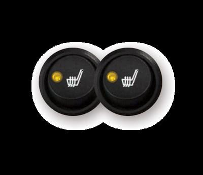
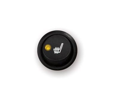
6 Page 6 Installation Instructions The skills you need: You need to be confident in your ability to: remove an automotive seat and reinstall to specification remove the upholstery and reinstall the upholstery remove and reinstall other trim such as the center console or parts of the instrument panel creating a hole in the trim for placement of the switch work with advanced airbag and occupant detection systems if equipped Automotive electrical experience or a basic understanding of electrical systems and the ability to disassemble and reassemble automotive seating is recommended. Recommended tools: multi-meter (ohm s, volts, continuity) Terminal crimpers Wire strippers Screw driver Wrenches Electrical tape Marker or pencil Drill Wire cutters Torque, socket and Allen wrenches Hog ring pliers Utility knife Needle nose pliers Ratchet Deep socket 1 Uni-bit (step bit) or 13/16 Drill bit Temperatures 1 temp 2 temp 3 temp This product features: Seats 1 seat 2 seats Heating Technology Copper Wire Available Switch Style Options for this product: Round Rocker
7 2 Series Wire Seat Heater Kit Page 7 Checklists: 2 Series Wire Product Contents Part Number Heating Element(s) Hardware HILO-M101 NTCPACK-M101 HPACK-EC-M9A HILO-M110 NTCPACK-M110 HPACK-EC-M9A HILO-M113 NTCPACK-M113 HPACK-EC-M9A HILO-M120 NTCPACK-M120 HPACK-EC-M9A HILO-M1XP NTCPACK-M1XP HPACK-EC-M9A HILO-M121 E27004M, E07195 HPACK-EC-M9A HILO-M128 E27195M, E07004 HPACK-EC-M9A HILO-M129 E27361M, E07004 HPACK-EC-M9A HILO-M020 E28195 HPACK-EC-M9A HILO-M0XP E28004M HPACK-EC-M9A HPACK-EC-M9A Component Hardware Contents Part Number Quantity Installation Extras (see contents below) HPACK-EC9-PRO 1 Power Harness (12 ) PH-EC12-12FT 1 Switch Harness (with switch) SWH-EC-M9-1 1 Hi / Off / Low Round Latching Switch SW-SPDT-06-24V 1 HPACK-EC9-PRO Installation Extras Sub-component Package Contents Quantity 4 TY-RAP 4 7. TY-RAP 2 Inline Fuse Holder Amp Fuse 1 Fast-On Terminal 1 Ring Terminal 1 Self-tapping Ground Screw 1 Manufactured in Michigan! USA

8 Page 8 Installation Instructions Installation 1. Pre-wire all components on your workbench and test with a multi-meter for continuity. Do NOT use a battery charger as a power source. Use a 12V D.C. power source. If there are any problems, see the troubleshooting page. 2. Locate vehicle fuse panel and determine routing of power harness. Each seat heater needs a separate 7.5A inline fuse (included) with a switched ignition 12V power source. 3. Install the ground wire ring terminal, from the power harness, to the fuse box ground screw. Clean terminals and grounding point of paint, grease, and dirt to ensure a good electrical connection. Never drill through the floor. 4. Disconnect and isolate the negative (ground) battery cable 5. Discharge latent electricity - pump the brakes a few times, and wait five minutes for the system to discharge. It is important to do this before disconnecting any airbag connectors. 6. Remove Seat(s) from vehicle. Care should be taken, as the sharp edges of the seat frame will scratch the interior trim. Use duct tape or padding to cover sharp areas before removing seat. 7. Remove the seat covers and verify that the heating elements fit. 8. Determine a location for mounting the switch. Cut a hole according to the dimensions shown in the wiring diagram. Connect switch harness to the back of the switch as shown in the wiring diagram (by wire color). 9. Locate area for heating elements by tracing element outline onto foam bun. Be sure that the cushion element is placed on the cushion bun, and that the back element is placed on the back bun. 10. Remove the adhesive release paper. This paper must be completely removed, as IT WILL BURN.

9 2 Series Wire Seat Heater Kit Page 9 Installation 1. Pre-wire all components on your workbench and test with a multi-meter for continuity. Do NOT use a battery charger as a power source. Use a 12V D.C. power source. If there are any problems, see the troubleshooting page. 2. Locate vehicle fuse panel and determine routing of power harness. Each seat heater needs a separate 7.5A inline fuse (included) with a switched ignition 12V power source. 3. Install the ground wire ring terminal, from the power harness, to the fuse box ground screw. Clean terminals and grounding point of paint, grease, and dirt to ensure a good electrical connection. Never drill through the floor. cable 4. Disconnect and isolate the negative (ground) battery 5. Discharge latent electricity - pump the brakes a few times, and wait five minutes for the system to discharge. It is important to do this before disconnecting any airbag connectors. 6. Remove Seat(s) from vehicle. Care should be taken, as the sharp edges of the seat frame will scratch the interior trim. Use duct tape or padding to cover sharp areas before removing seat. 7. Remove the seat covers and verify that the heating elements fit. 8. Determine a location for mounting the switch. Cut a hole according to the dimensions shown in the wiring diagram. Connect switch harness to the back of the switch as shown in the wiring diagram (by wire color). 9. Locate area for heating elements by tracing element outline onto foam bun. Be sure that the cushion element is placed on the cushion bun, and that the back element is placed on the back bun. 10. Remove the adhesive release paper. This paper must be completely Manufactured in Michigan! USA
10 Page 10 Installation Instructions Heating Element Information Here is a list of the element part numbers in each 2 Series kit: Regular Stock Kits Kits with 2 Heating Elements (both must be used) Kit P/N: Element Pack P/N: Cushion Back Rest HILO-M101 NTCPACK-M101 E27092M E07092 HILO-M110 NTCPACK-M110 E27105M E07094 HILO-M113 NTCPACK-M113 E27106M E07107 HILO-M120 NTCPACK-M120 E27195M E07195 HILO-M1XP NTCPACK-M1XP E27004M E07004 Kits with 1 Heating Element (for the back rest or the cushion) HILO-M020 E28195M HILO-M0XP E28004M If you ever think about mixing and matching element, here s a guide on what is allowed: Acceptable Mix & Match Alternate Patterns (not regular stock part numbers) HILO-M121 E27004M E07195 HILO-M128 E27195M E07004 HILO-M122 E27092M E07094 HILO-M123 E27092M E07107 HILO-M124 E27105M E07092 HILO-M125 E27105M E07107 HILO-M126 E27106M E07092 HILO-M127 E27106M E07094 HILO-M129 E27361M E07004
11 2 Series Wire Seat Heater Kit Page 11 Heating Element Information HILO-M101 HILO-M110 E E E27092M 12 E27105M HILO-M113 HILO-M1XP E E E27106M 9 2. E27004M Manufactured in Michigan! USA
12 Page 12 Installation Instructions Heating Element Information HILO-M120 Installation Features The heating elements in the HILO-M120 (E27195M & E07195) are made to accommodate several different seat styling layouts. The elements can be installed so that the cut-out is aligned horizontally or vertically. When installing the element vertically, run the wiring harness along the bolster tie-down area or, if the wire lays atop the foam bun and you are concerned about the user feeling the harness, use a razor knife to create a slit in the foam bun and lay the harness into the foam bun. HILO-M120 Horizontal E Vertical E Horizontal E27195M 2. Vertical E27195M 2. Vertical E07195 Horizontal E Horizontal E27195M 2. Vertical E27195M 2.


13 2 Series Wire Seat Heater Kit Page 13 HILO-M020 Heating Element Information HILO-M0XP Horizontal E27895M 2. E28004M 8 Figure 1: Installing the heating elements The seat heater element adheres 100% to the foam bun following the surface into the listing gaps. If your heating elements have a pre-made hole, align the hole with the tie-down. The listing channels or the Velcro hold-downs should line up with the cutouts in the heating elements. Fold the narrow bridges of the element down into the trench as shown in these illustrations. Manufactured in Michigan! USA
14 Page 14 Installation Instructions This is the 4 Pin connector at the end of the element harness. Disconnect the wire harness and use a multi-meter to check for continuity. Probe Pin 1 and Pin 2 at 20K Ohms. Normal reading should be 6,500 to 15,000 Ohms. Figure 2: Troubleshooting the heating elements Probe Pin 3 and Pin 4 at 20 Ohms. Normal reading is between 1.5 and 22 Ohms. If Pin 4 is a blue wire, this system is equipped with a mandatory backrest heating element. The two elements are wired in series. Trace on the blue wire harness to find the backrest element connector. The backrest element can be tested for Ohms on its own. The cushion element must have the backrest element connected during the Ohm reading test.
15 2 Series Wire Seat Heater Kit Page 15 Troubleshooting of the electrical system If the system does not heat up, check the following: To test the unit you must sit in it for at least a 5-minute period in which the heat has time to reach the seat surface. Check the fuse utilized during the installation. Ensure that all connections are properly mated and that the 12V DC and ground wires are properly installed. (See seat heater wiring diagram) A break in the heating element circuit. To check for this, pull on the wires at all connectors to verify they are properly seated in the connector. Don t forget the connector on the back element. Also check for continuity at the 4 pin connector. The cushion and back elements must be connected and use a multi-meter set to ohms. See Figure 1 A low voltage condition on the controller input from the fuse box. To verify the voltage input, use a multi-meter set to volts, across red AND black wires at controller module (it should read 11-15V). If the heating elements, switch, and seat harness test OK, then a power problem exists, check the following: Using a multi-meter or a test light, start at the power connection and trace back through all of the connectors and the switch to determine where the power loss is occurring. Repair as necessary. If the fuse continues to fail, check the following: Each pair of heating elements that are installed in the vehicle must have their own fuse. A poor ground connection. Check connections or try another grounding point. Another possible cause is the fuse used for power is computer controlled (try another fuse location). IF YOU HAVE ANY QUESTIONS REGARDING THE INSTALLATION OF CHECK CORPORATION SEAT HEATERS, PLEASE CALL OUR HOTLINE AT , 8AM TO 5PM EASTERN STANDARD TIME. Manufactured in Michigan! USA


16 Page 16 Installation Instructions Using fuse-taps Figure 3: Connecting Power If you are using fuse taps, it is important to draw from the correct side of the fuse When connecting the red wire on the power harness connect it to the cold side of the fuse. Red = Cold Side [warning] do not fuse this seat heater system with a fuse greater than a 7.5 amp value Using Optional Add-A-Fuse Accessory (Purchased Separately) This adaptor is rated to handle up to 10 amps on the accessory fuse. Prong indicated in photo below must go to the DC +12V hot side of the fuse receptacle. In the example photo, the 7.5 amp fuse runs the seat heater accessory; the 10 amp fuse is the original amperage fuse from the fuse box. The 7.5 Photo: Add-A-Fuse with fuses Photo: Add-A-Fuse installed in fuse box To: Seat Heater Factory Fuse amp fuse is in line with the red wire for connection to the DC +12V seat heater wire. + VOLTAGE COLD
17 2 Series Wire Seat Heater Kit Page 17 Thrown for a loop? Have a great idea? Questions? We re listening and we re here to help. Call (877) Or Office Hours 8:30 AM to 5:00 PM Eastern 5:30 AM to 2:00 PM Pacific Support sales@checkcorp.com SeatHeater.com HeatYourSeat.com Check Corporation 1800 Stephenson Highway, Troy, Michigan, USA Manufactured in Michigan! USA
18 Page 18 Installation Instructions
 A-A HILO-M101, HILO-M110 HILO-M113, HILO-M1XP HILO-M020 HILO-M0XP Manufactured in Michigan!")
19 2 Series Wire Seat Heater Kit Page 19 Power Harness B-B Switch Harness C-C Cushion Heating Element ( 3 versions ) A-A HILO-M101, HILO-M110 HILO-M113, HILO-M1XP HILO-M020 HILO-M0XP Manufactured in Michigan! USA


20 Page 20 Installation Instructions More Products From Check Corporation: COPPER Wire 1ROUND 1FLAT 2ROUND JOINED 2FLAT
Wire Seat Heater Installation Instructions
 COPPER Wire Wire Seat Heater Installation Instructions 1-Seat Coverage 2-Temperature Settings Part# HILO-M1xx HILO-M0xx Document: LIT-MAN-HILO-2 Rev D 12/30/13 Check Corporation 1800 Stephenson Highway
Document: LIT-MAN-UNV-2 Rev A 10/21/15
 Document: LIT-MAN-UNV-2 Rev A 10/21/15 Limited Warranty This Product is warranted to be free from defects in manufacturing and workmanship and is guaranteed to work for three years or 36,000 miles, or
TOYOTA CAMRY LE / SE / XLE DUAL SEAT HEATER KIT Section I Pre-Installation Check
 Section I Pre-Installation Check Kit Part Number: 250-1897 3 General Applicability Camry LE / SE / XLE 5 4 1 Recommended Sequence of Application Item # Accessory 1 Wiring 2 Elements 3 2 Kit Contents Item
RoadComfort TM. Installation Manual Vibration Massage & Heat
 RoadComfort TM Vibration Massage & Heat Installation Manual 1-562-447-1780 WWW.RELAXOR.COM Table of Contents I Required tools II System Configuration III Motor Placement Bottom IV Motor Placement Back
Flexwire Highlights. 1. A Solution to Center Listings and Seat Heater Installations.
 Seat Heaters Universal: Dual Temperature Flex-Wire: Twin Comfort Pads Installation instructions for the Flex-Wire seat heating system SH-FW-01 The All New Flex-Wire Seat Heater combines New Multi-Strand
ROUSH Active IO Exhaust. Installation Instructions P/N: (R LITE) Fastback GT Convertible GT V8
 Fastback GT Convertible GT V8") Installation Instructions P/N: 422128 (R1318-5231LITE) Fastback GT Convertible GT V8 39555 Schoolcraft Rd, Plymouth MI, 48170 800.59.ROUSH ROUSH Active IO Exhaust Installation Instructions P/N: 422128
Installation Instructions P/N: 422128 (R1318-5231LITE) Fastback GT Convertible GT V8 39555 Schoolcraft Rd, Plymouth MI, 48170 800.59.ROUSH ROUSH Active IO Exhaust Installation Instructions P/N: 422128
Installation Instructions
 Installation Instructions AMP RESEARCH Power Step by Bestop Automatic Retracting Running Board Vehicle Application Nissan Titan King Cab 2004 and newer (5 ft.) Part Number: 75106-01 Nissan Titan Crew Cab
TOYOTA FJ CRUISER 2007 AUXILIARY LIGHTS Preparation
 TOYOTA FJ CRUISER 2007 AUXILIARY LIGHTS Preparation Part Number: PT297-35061 Kit Contents Item # Quantity Reqd. Description 1 2 Driving Lamp Assembly 2 1 Switch Harness 3 1 Lamp Harness 4 2 Stone Shield
SCION xd INTERIOR LIGHTING UPGRADE Preparation
 Preparation Part Number: PTS21-52085 Light Guide Kit Contents Item # Quantity Reqd. Description 1 1 Controller Board, 4 color programmed w/ Bracket 2 1 RGB, LED Engine wire harness 3 2 14mm Light Rod,
Conflicts: Vehicles with a sunroof
 Toyota 4Runner Non/MR 2010-10.2 Overhead Video Part Number: 00016-00110; Fit Kit -00110-15, Beige 00016-00120; Fit Kit -00120-15, Gray Accessory Code: ED6 Conflicts: Vehicles with a sunroof Kit Contents:
Seat Comfort Systems Ventilation/Heater Installation Instructions
 Seat Comfort Systems Ventilation/Heater Installation Instructions KIT P/N: SCS00000C3 IMPORTANT: THE VENTILATION SYSTEM DRAWS AIR FROM THE CABIN AND MUST HAVE OPEN ACCESS THROUGH THE BOTTOM OF THE SEAT
TOYOTA TACOMA EC REARVIEW MIRROR Preparation
 Preparation Part Number: PT374-35052 Kit Contents Item # Quantity Reqd. Description 1 1 AD Mirror Assembly 2 1 Hardware bag Hardware Bag Contents Item # Quantity Reqd. Description 1 1 T-tap Connectors,
Toyota 4RUNNER With/MR Overhead Video
 Toyota 4RUNNER With/MR 2010-10.2 Overhead Video Part Number: 00016-00110; Fit Kit-00110-14, Beige 00016-00120; Fit Kit-00120-14, Gray Accessory Code: ED7 Conflicts: Vehicles without a sunroof Kit Contents:
INSTALLATION. DRIVING LIGHTS for FLHT/FLHX/FLHR 5005
 DRIVING LIGHTS for FLHT/FLHX/FLHR 5005 PARTS INCLUDED 1 Right Driving Light Assembly 1 Left Driving Light Assembly 1 Right Driving Light Bracket 1 Left Driving Light Bracket 4 Driving Light Bracket Plugs
CSA CERTIFIED Conforms to UL 507
 Installation tion Instructions Please read and save these instructions! TURBO/MAXX12 Volt All Weather RV Ventilator Fans P/N 00-965001 Deluxe Model 1200T WITH THERMOSTAT P/N 00-965007 Standard Model 3550
Remove 4 circled pins. Route wiring along dashed line. Remove the 2 9mm nuts and black retaining plate that secure extractor.
 2015 Ford Mustang Turn Signal Hood Kit Parts List: Quantity: Tool List: Bracket & pre-installed lamp 2 Flat head screwdriver Wiring harness 1 Phillips screwdriver PB-3660 Parts Bag 1 Ratchet & Socket set
IT IS IMPORTANT THAT YOU OBTAIN THE CORRECT INFORMATION FOR YOUR VEHICLE, OR DAMAGE TO THE WIRING SYSTEM COULD OCCUR.
 Instructions for Universal Harness PRINT THESE INSTUCTIONS Gentex Mirror Installation Instructions Provided by www.rearviewautomirrors.com These instructions have been prepared to provide you with details
Remove the 3-11mm nuts holding mirror on. Don t drop the nuts!
 2005-2012 Ford Mustang Puddle Lamp Kit Parts List: Quantity: Tool List: LED Lamps 2 Flat head screwdriver Seals 2 Ratchet & Socket set OR Nuts 2 Adjustable Wrench Wiring harness 1 Drill & 11/16 th bit
Seat Heaters Universal: Dual Temperature Carbon Fiber: Twin Comfort Pads. Installation instructions for seat heating systems SH-R Feb 2009.
 Seat Heaters Universal: Dual Temperature Carbon Fiber: Twin Comfort Pads Installation instructions for seat heating systems SH-R-01 03 Feb 2009. Index 1. General safety advice...............................................................
Service Bulletin
 Service Bulletin 14-009 February 13, 2014 ATB 50862 (1402) Driver s Seat Heater Shuts Off After Turning On AFFECTED VEHICLES Year Model Trim VIN Range 2011 13 Odyssey EX-L, Touring ALL SYMPTOM The driver
USB Charge Port Installation Instructions
 USB Charge Port Installation Instructions Lifetime Technical Support support@logolites.com 770-476-7322 www.logolites.com Manual 100-0014C Thank you for purchasing a Logo Lites USB Charge Port! USB Charge
Front Bucket Seat Upholstery
 Specter Off-Road, Inc. 21600 Nordhoff St. Chatsworth, CA 91311 USA www.sor.com, (818)882-1238, Fax: (818) 882-7144 sor@sor.com Luxury Seat Upholstery Installation Instructions Front Bucket Seat Upholstery
10 Year Limited Warranty
 Power. On Your Terms. 10 Year Limited Warranty PHI 2.7 TM PHI 3.5 TM 60A SIMPLIPHI POWER, INC. REV020618 10 Year Limited Warranty: PHI 2.7 TM PHI 3.5 TM 60A 24V 48V Limited Pro-Rated Warranty Coverage
INSTALLATION CONSTELLATION DRIVING LIGHTS 5009
 INSTALLATION CONSTELLATION DRIVING LIGHTS 5009 PARTS INCLUDED 1 Right Driving Light with Turn Signals 1 Left Driving Light with Turn Signals 1 Installation Component Kit Including: 8 Insulated Male Spades
Scion xa SATELLITE RADIO TUNER Preparation
 Preparation Part Number: PTS31-00051 Kit Contents Item # Quantity Reqd. Description 1 1 Antenna, Interior 2 1 Antenna Tape Pad 3 1 Wire Harness 4 1 Bracket, Floor 5 3 Hardware Bags 6 3 Templates 7 1 SIRIUS
INSTALLATION. led fairing lights for gl
 for gl1800 4627 Fits: 01-up GL1800 Parts Included 4 7-Color Lizard Lights 1 7-Color Controller/Switch 1 Hardware Kit including: 4 Replacement Adhesive Pads 4 18 Extensions 1 Double Male Lizard Light Connector
ECS R32 Exhaust Flap Manual Override Installation Instructions
 Installation Procedures This tutorial is provided as a courtesy by. Proper service and repair procedures are vital to the safe, reliable operation of all motor vehicles as well as the personal safety of
3-5 Hours Professional installation recommended
 I N S T A L L A T I O N G U I D E APPLICATION MODEL YR PART # Toyota Tacoma Double Cab 2005 - up 75142-01A Toyota Tacoma Access Cab* 2005 - up 75142-01A * Modification required to running board assembly.
SH-R-00 Seat Heaters Universal: Dual Temperature Carbon Fiber: Twin Comfort Pads
 SH-R-00 Seat Heaters Universal: Dual Temperature Carbon Fiber: Twin Comfort Pads Installation Instructions Distributed by SR-H-00 Installation Guide Page 1 Index 1. General safety advice...............................................................
TOYOTA YARIS HATCHBACK INTERIOR LIGHT UPGRADE Preparation
 Preparation Part Number PTS21-52062-08 NOTE: Part number of this accessory may not be the same as the part number show Kit Contents Item # Quantity Reqd. Description 1 1 12 Light Guide 2 1 7 Light Guide
AEROMOTIVE Part # and F-Body Fuel System Kit INSTALLATION INSTRUCTIONS
 AEROMOTIVE Part # 17101 and 17102 93-97 F-Body Fuel System Kit INSTALLATION INSTRUCTIONS CAUTION: Installation of this product requires detailed knowledge of automotive systems and repair procedures. We
SOS LOWERING KIT INSTALLATION MANUAL Leaf Spring Shackle and Hardware
 Page 12 PARTS INCLUDED IN KIT Front Coil Spring Perch, Sleeve and Bump Stops SOS LOWERING KIT INSTALLATION MANUAL Leaf Spring Shackle and Hardware SOS 2050 Axle Perches Bottom Plates APPLICATIONS 2007
Jeep Wrangler (TJ)
") INSTALLATION GUIDE APPLICATION MODEL YR PART # Bestop PART # Jeep Wrangler (TJ) 2003 2006 10-03315-10 751-01 INSTALLATION TIME 3:00 hrs SKILL LEVEL 1 2 3 4 4= Experienced TOOLS REQUIRED Safety goggles
INSTALLATION GUIDE APPLICATION MODEL YR PART # Bestop PART # Jeep Wrangler (TJ) 2003 2006 10-03315-10 751-01 INSTALLATION TIME 3:00 hrs SKILL LEVEL 1 2 3 4 4= Experienced TOOLS REQUIRED Safety goggles
Toyota Prius C 2015 Frameless EC Mirror w/ Compass & HomeLink
 Toyota Prius C 2015 Frameless EC Mirror w/ Compass & HomeLink Part Number: 00016-05463 Accessory Code: ME4000 Note: This accessory requires replacement A-Pillar clip 62217-52120 to complete the installation
Main Harness Quantity: 1
 Smart Engine Start INSTALLATION MANUAL Genuine Part # : H001SVA900 Vehicle Model : WRX Kit Contents Service P/N: H001SVA910 Service P/N: H001SVA820 NOT USED NOT USED SES ECU Quantity: 1 Double-sided tape
Model A Turn Signal Kit Installation Guide
 Model A Turn Signal Kit Installation Guide Creative Connections, Inc. Consumer Hot Line: 888-471-LOGO 770-476-7322 In Atlanta, GA http://www.logolites.com P/N: 100-005/K 2008 Creative Connections, Inc.
Conflicts: Vehicles without a sunroof Vehicles with a single sunroof
 Toyota Sienna (Dual Sunroof) 2011-10.2 Overhead Video Part Number: 00016-00110 00016-00110-17 Fit Kit 00016-00120 00016-00120-17 Fit Kit Accessory Code: ED5 Conflicts: Vehicles without a sunroof Vehicles
TOYOTA HIGHLANDER RUNNING BOARD HIGHLANDER HV Preparation
 Preparation Part Number: PT738-48080 Kit Contents Item # Quantity Reqd. Description 1 1 Driver Side Running Board 2 1 Passenger Side Running Board 3 4 /Middle Mount Bracket 4 2 Rear Mount Bracket 5 2 Rear
STāSIS Engineering R8 Brake System
 STāSIS Engineering R8 Brake System Brake Kit Installation Instruction Application Guide SE811-B30-91-00 R8 Brake System Special Tools Required Qty Description 1 10 MM Allen Head Socket 1 M10 Triple Square
INSTALLATION GUIDE. AV8900H Dual Multimedia Headrest Replacement System
 INSTALLATION GUIDE AV8900H Dual Multimedia Headrest Replacement System NOTICE OF INTENDED INSTALLATION AND USE AV8900H VIDEO PRODUCTS ARE NOT INTENDED FOR VIEWING BY THE DRIVER, AND ARE TO BE INSTALLED
MUSTANG GT
 MAXFLOW FUEL PUMP BOOSTER Installation Instructions 2015-2018 MUSTANG GT P/N: 5A102-036 * Legal in California only for racing vehicles which may never be used or registered or licensed for use upon a highway.
INSTALLATION CONSTELLATION DRIVING LIGHTS 5009
 INSTALLATION CONSTELLATION DRIVING LIGHTS 5009 PARTS INCLUDED 1 Right Driving Light with Turn Signals 1 Left Driving Light with Turn Signals 1 Installation Component Kit Including: 8 Insulated Male Spades
Please note that these instructions apply to the Toyota Towing Wire Harness. The part you re looking for is PT
 This download was hosted by LanderFan.com, your source of tips, tricks, hacks, how-to articles, and other newsy tidbits related to the new (2014+) Toyota Highlander.! Please note that these instructions
Porsche L and 3.6L Unichip PnP Installation Instructions
 Porsche 996 3.4L and 3.6L Unichip PnP Installation Instructions and Warranty Information v1.0, 1 June 2007 Tools Required 10mm socket, ¼-inch or 3/8-inch ratchet, 6-inch ratchet extension, and a 10mm combination
advanced FLOW engineering Instruction Manual P/N: Make: Can-AM Model: Maverick Year: Engine: 1000cc
 advanced FLOW engineering Instruction Manual P/N: 85-80066 Make: Can-AM Model: Maverick Year: 2013-2016 Engine: 1000cc Please read the entire instruction manual before proceeding. Ensure all components
Ford F-150 Supercrew A (2004 Heritage) Ford F-150 Super Cab A
 Ford F-150 Super Cab A") INSTALLATION GUIDE APPLICATION LENGTH MODEL YR PART # Ford F-150 Supercrew 79 1999-2004 75111-01A (2004 Heritage) Ford F-150 Super Cab 72 1999-2003 75111-01A INSTALLATION TIME 3:00 hrs SKILL LEVEL 1 2
INSTALLATION GUIDE APPLICATION LENGTH MODEL YR PART # Ford F-150 Supercrew 79 1999-2004 75111-01A (2004 Heritage) Ford F-150 Super Cab 72 1999-2003 75111-01A INSTALLATION TIME 3:00 hrs SKILL LEVEL 1 2
TOYOTA TUNDRA TVIP V3 (RS3000) Section I - Installation Preparation
 Section I - Installation Preparation") Section I - Installation Preparation Part Number: 0886-34861 Section I - Installation Preparation Kit Contents Item # Quantity Reqd. Description 1 1 Wire Harness 2 1 Status Monitor 3 1 Piezo Buzzer 4 1
Section I - Installation Preparation Part Number: 0886-34861 Section I - Installation Preparation Kit Contents Item # Quantity Reqd. Description 1 1 Wire Harness 2 1 Status Monitor 3 1 Piezo Buzzer 4 1
Installation MKIV Headlight Housings with Fog Lamps (Procedures apply to both MKIV Jetta and Golf)
") Page 1 This tutorial is provided as a courtesy by ECS Tuning. Service Procedure Installation Proper service and repair procedures are vital to the safe, reliable operation of all motor vehicles as well
Page 1 This tutorial is provided as a courtesy by ECS Tuning. Service Procedure Installation Proper service and repair procedures are vital to the safe, reliable operation of all motor vehicles as well
TOYOTA HIGHLANDER TRAILER WIRE HARNESS Preparation
 Preparation Part Number: PT219-48111 Kit Contents Item # Quantity Reqd. Description 1 1 Converter 2 1 Flat 4-pin wire harness 3 5 Plastic tie 4 1 Special plastic tie for stud mount 5 1 Packing 6 2 Bolt
Vehicle Rear Observation System With Integrated Parking Sensors
 Vehicle Rear Observation System With Integrated Parking Sensors Model: CAMSBAR Installation/User Manual Features: 2.5" LCD Color Display 2 Ultra Sonic Rear Obstacle Sensors On-screen Display Function Automatically
INSTALLATION FORK MOUNTED DRIVING LIGHTS 5008
 5008 PARTS INCLUDED 1 Right Fork Mount Assembly 1 Left Fork Mount Assembly 2 H3 Driving Light Assemblies 1 12-Pin Wiring Adapter 1 Hardware Kit for Fork Mount Driving Lights, Including: 6 5/16-18 Nylock
INSTALLATION GUIDE. APPLICATION MODEL YR PART # Toyota Tundra Double Cab Toyota Tundra CrewMax
 INSTALLATION GUIDE APPLICATION MODEL YR PART # Toyota Tundra Double Cab 2007-10-03566-65 Toyota Tundra CrewMax 2007-10-03566-79 INSTALLATION TIME 3:00 hrs SKILL LEVEL 1 2 3 = Experienced TOOLS REQUIRED
YARIS 4-DOOR 2007 INTERIOR LIGHT UPGRADE
 Document # 3999 4/26/06 4-DOOR 2007 INTERIOR LIGHT UPGRADE Preparation Part Number: 00016-52060 Code: IL1 Kit Contents Item # Quantity Reqd. Description 1 1 12 Light Guide 2 1 7 Light Guide 3 1 Hardware
Race Sport Lighting RSUKIT LED UNDERBODY KIT INSTALLATION GUIDE
 Race Sport Lighting RSUKIT LED UNDERBODY KIT INSTALLATION GUIDE PARTS LIST (INCLUDED IN THE KIT) 1 x LED Control Center Box 2 x 48 RGB Aluminum Channel LED Bars 2 x 36 RGB Aluminum Channel LED Bars 1 x
2015+ S550 MUSTANG Battery Relocation Kit WR-BTRYRELOKIT-LH WR-BTRYRELOKIT-RH
 2015+ S550 MUSTANG Battery Relocation Kit WR-BTRYRELOKIT-LH WR-BTRYRELOKIT-RH The Watson Racing Battery Relocation Kit is NOT designed to protect you in the case of an accident, and therefore is INTENDED
Power. On Your Terms.
 Power. On Your Terms. 10 YEAR LIMITED WARRANTY PHI 1310 TM 1 SIMPLIPHI POWER, INC. REV102016 10 YEAR LIMITED WARRANTY: PHI 1310 TM LIMITED PRO-RATED WARRANTY COVERAGE The SimpliPhi Power PHI 1310 as supplied
SCION tc ILLUMINATED DOOR SILLS Preparation
 Preparation Part Number: PTS21-21070 Kit Contents Item # Quantity Reqd. Description 1 2 Hardware Kit w/ power harness 2 1 Front Left Illuminated Door Sill Protector 3 1 Front Right Illuminated Door Sill
TOYOTA VENZA 2009 TRAILER WIRE HARNESS Procedure
 Part Number: PT791-0T099 Kit Contents Item # Quantity Reqd. Description 1 1 Trailer Wire Harness Module 2 1 4-Flat Harness 3 1 Battery Power Wire Harness 4 1 Mounting Bracket, 4-Flat 5 2 Screw #10-24 6
Audi B9 A4 & S4 Carbon Fiber Steering Wheel Trim Installation Instructions
 Audi B9 A4 & S4 Carbon Fiber Steering Wheel Trim Installation Instructions Proper service and repair procedures are vital to the safe, reliable operation of all motor vehicles as well as the personal safety
Model HPX60 Series Automatic Battery Charger User s Manual Rev. 1.0 October 17, 2006
 B R A N D Model HPX60 Series Automatic Battery Charger User s Manual Rev. 1.0 October 17, 2006 For Sales, Support and Service phone: 407-331-4793 fax: 407-331-4708 website: www.xenotronix.com email: information@xenotronix.com
I N S T A L L A T I O N G U I D E. Ford Transit - Single Sided A (All slider and barn door models)
") I N S T A L L A T I O N G U I D E APPLICATION MODEL YR PART # Ford Transit - Single Sided 2014-2017 76159-01A (All slider and barn door models) INSTALLATION TIME 3-5 Hours Professional installation recommended
I N S T A L L A T I O N G U I D E APPLICATION MODEL YR PART # Ford Transit - Single Sided 2014-2017 76159-01A (All slider and barn door models) INSTALLATION TIME 3-5 Hours Professional installation recommended
TOYOTA VENZA 2009 TRAILER WIRE HARNESS Procedure
 Part Number: PT791-0T099 Kit Contents Item # Quantity Reqd. Description 1 1 Trailer Wire Harness Module 2 1 4-Flat Harness 3 1 Battery Power Wire Harness 4 1 Mounting Bracket, 4-Flat 5 2 Screw #10-24 6
INSTALLATION GUIDE Car Show Dual DVD Headrest Replacement System
 INSTALLATION GUIDE Car Show Dual DVD Headrest Replacement System NOTICE OF INTENDED INSTALLATION AND USE CAR SHOW VIDEO PRODUCTS ARE NOT INTENDED FOR VIEWING BY THE DRIVER, AND ARE TO BE INSTALLED ONLY
Container Fountain Kit with LED Light
 Container Fountain Kit with LED Light REMINDER CALL 1-888-755-6750 BEFORE RETURNING TO STORE. PACKAGE CONTENTS Questions, problems, missing parts? Before returning to your retailer, call our customer service
ATF Small Block Ford Starter Shim and Adjusting Cam Installation Instructions
 ATF Starter Shim ATF Adjusting Cam -CAUTION- Always use care when working on, around or underneath a vehicle. Wear eye protection, support the vehicle safely, etc. Please be sure to read all of these instructions
TOYOTA RAV4/HV INTERIOR LIGHT KIT Preparation
 Preparation Part Number: PT413-42130 Kit Contents Item # Quantity Reqd. Description 1 1 Wire Harness 2 3 Hardware Bag Contents Item # Quantity Reqd. Description 1 20 Cable Tie 2 2 Scotchlok 3 2 Foam Pad
SCION xb AUTO-DIMMING MIRROR Preparation
 Preparation Part Number: PT374-02090 Kit Contents Item # Quantity Reqd. Description 1 1 AD Mirror Assembly w/ PRNDL 2 1 Hardware bag Hardware Bag Contents Item # Quantity Reqd. Description 1 2 T-tap Connectors,
LIGHTNING PLUS 120 WATT / 6 OUTLET VOLT POWER SUPPLY & STROBE LIGHT KIT 6 Different Light Patterns 8006 SERIES INSTALLATION INSTRUCTIONS
 LIGHTNING PLUS 120 WATT / 6 OUTLET 12-24 VOLT POWER SUPPLY & STROBE LIGHT KIT 6 Different Light Patterns 8006 SERIES INSTALLATION INSTRUCTIONS Your purchase of Wolo s LIGHTNING PLUS strobe light system
pg 2 Disassembly, Wire and Amplifier Plate Installation pg 9 Glovebox Subwoofer Installation pg 13 Kick Panel Speakers Installation
 RZ3-5KRC RZR XP1000 & 2015+ RZR900 with Ride Command SSV Works 5 Speaker Audio Kit pg 2 Disassembly, Wire and Amplifier Plate Installation pg 9 Glovebox Subwoofer Installation pg 13 Kick Panel Speakers
TOYOTA COROLLA EC REARVIEW MIRROR Preparation
 Preparation Part Number: PT374-02090 Kit Contents Item # Quantity Reqd. Description 1 1 AD Mirror Assembly w/ PRNDL 2 1 Hardware bag Hardware Bag Contents Item # Quantity Reqd. Description 1 2 T-tap Connectors,
Tru-Billet Climate Control Knob Installation Instructions
 P/N S197-525-07 2007-08 Tru-Billet Climate Control Knob Installation Instructions Thank you for your purchase of SilverHorse Racing products. Please read all directions before beginning the installation.
INSTALLATION INSTRUCTIONS
 INSTALLATION INSTRUCTIONS Part# 22-2719 Complete Mounting System for Dual Viair Compressors For the most up-to-date instructions please visit www.updownair.com www.updownair.com 833-226-4863 I M P O R
Setup and Configuration Guide Universal Switch Interface
 Table of Contents J1939 inmotion Cell Setup and Configuration Guide Universal Switch Interface Overview... 2 Warnings... 3 J1939 inmotion Cell Technical Details... 4 inmotion Cell Installation Steps...
AEROMOTIVE Part # Generic Fuel System Kit INSTALLATION INSTRUCTIONS
 AEROMOTIVE Part # 17126 Generic Fuel System Kit INSTALLATION INSTRUCTIONS CAUTION: Installation of this product requires detailed knowledge of automotive systems and repair procedures. We recommend that
Seat Comfort Systems
 Seat Comfort Systems Revitalizer Massage Installation Manual SCS6MC Seat Comfort Systems www.seatcomfort.com Important Safety Instructions The Reviltalzer Massage System is a vibration system that has
PHASE 3 POWERSPORTS AUDIO KIT RZR POLARIS. pg 2 Disassembly, Wire and Amplifier Plate Installation. pg 9 Glovebox Subwoofer Installation
 POLARIS RZR PHASE 3 POWERSPORTS AUDIO KIT pg 2 Disassembly, Wire and Amplifier Plate Installation pg 9 Glovebox Subwoofer Installation pg 13 Kick Panel Speakers Installation pg 25 MRB3 and Dash Kit Installation
Upper Class Grille Main grille INSERT - #54127 / #54131 / #54133 / #51127 / #51131 / 51133
 Parts included (1) - Main Full Opening - Polished - Part #54127 OR 1 Bar - Polished - Part #54131 OR 2 Bar - Polished - Part #54133 OR Full Opening - Black - Part #51127 OR 1 Bar - Black - Part #51131
Hummer H up A Hummer H3T up A
 INSTALLATION GUIDE APPLICATION MODEL YR PART # Hummer H3 2006 - up 5116-01A Hummer H3T 2009 - up 5116-01A INSTALLATION TIME 3:00 hrs SKILL LEVEL 1 2 3 = Experienced TOOLS REQUIRED Safety goggles Measuring
Installation Manual TWM Performance Short Shift Kit Stage 1 and Stage 2 MazdaSpeed 6
 Page 1 Installation Manual TWM Performance Short Shift Kit Stage 1 and Stage 2 MazdaSpeed 6 Please Note: It is preferable to park on a flat surface, as you will have to engage and disengage the hand brake
AEROMOTIVE Part # A2000 Fuel Pump Kit INSTALLATION INSTRUCTIONS
 AEROMOTIVE Part # 17202 A2000 Fuel Pump Kit INSTALLATION INSTRUCTIONS CAUTION: Installation of this product requires detailed knowledge of automotive systems and repair procedures. We recommend that this
TECHNICAL INSTRUCTIONS
 TECHNICAL INSTRUCTIONS 76-50213-00 Solar Charger Kit This kit provides the necessary parts and instructions to install an optional Battery Solar Charger Kit. The solar panel charging system will help maintain
Installation Instructions. Fog Lights. The lamps get very hot when they have been in use. Do not touch them as they may cause burns.
 2100X Installation Instructions Thank you very much for purchasing PIAA product. Please read this entire manual before installation and use of this product. Fog Lights For Installers Please give this Installation
Installation Instructions Supertop for Truck
 Installation Instructions Supertop for Truck Vehicle Application: Toyota Tacoma Double Cab 2005 - Current (5 ft.) Part Number: 76308 US Patent 6827391 www.bestop.com - We re here to help! Visit our web
Model 377, 379, 386, 388, Sleeper no window
 Installation Manual Model 377, 379, 386, 388, 389 63 Sleeper no window 2390 Blackhawk Road P.O. Box 6007 Rockford, IL 61125 www.nitesystem.com 1-866-204-8570 NITE Plus Installation Procedures 1-2 Table
Heavy Duty Air Command
 2097 / 2227 Heavy Duty Air Command INSTALLATION INSTRUCTIONS Congratulations on your purchase of a new Air Command kit. This kit was designed to provide inflation control of your air helper springs. This
Air Conditioner for M915 A0/A1 Truck
 RD-2-4530-0 Air Conditioner for M915 A0/A1 Truck INSTALLATION INSTRUCTIONS Install refrigerant compressor per instructions provided with compressor mount kit. CAUTION: Edges of sheet metal can be sharp!
TORCH Main Grille Main grille INSERT - # / # Chevrolet Silverado
 Parts included (1) TORCH Grille - Main (1) 40 LED - Part #6311271 OR Stealth - Part #6311271-BR OR (1) 30 LED - Part #6311281 OR Stealth - Part #6311281-BR Hardware included (1) - Large Bottom Mounting
TOYOTA SIENNA TRAILER WIRE HARNESS Preparation
 Preparation Part Number: PT791-08150 (non-se) PT791-08102 (SE only) Kit Contents Item # Quantity Reqd. Description 1 1 Trailer Module Harness 2 1 4-Flat Harness 3 1 Battery Power Wire Harness 4 1 Mounting
Installation Manual TWM Performance Kia Forte Short Shifter
 Installation Manual TWM Performance Kia Forte 2009+ Short Shifter Begin the installation by parking on a flat surface, as you will have to engage and disengage the hand brake and shift from gears to neutral.
Scion xb EC Rearview Mirror w/ Shift Light Preparation
 2008 - Preparation Part Number: 00016-79800 Accessory Code: YM10 Kit Contents Item # Quantity Reqd. Description 1 1 Mirror Assembly w/ PRNDL 2 1 Hardware bag 3 1 Installation Manual Hardware Bag Contents
A/C PRESSURE MONITOR INSTALLATION INSTRUCTIONS SYSTEM OPERATION GREEN INDICATOR LIGHT
 A/C PRESSURE MONITOR INSTALLATION INSTRUCTIONS Do not attempt to clean or inspect anything while the engine is running. Cleaning and inspection must be done by a certified mechanic. All A/C service must
Scion xb EC Rearview Mirror Preparation
 Scion xb 2010 - EC Rearview Mirror Preparation Part Number: 00016-09101 Code: CM9 Kit Contents Item # Quantity Reqd. Description 1 1 AD Mirror Assembly w/ Compass and Homelink 2 1 Hardware bag Hardware
TOYOTA Yaris Hatchback EC REARVIEW MIRROR Preparation
 Preparation Part Number: PT374-02090 Kit Contents Item # Quantity Reqd. Description 1 1 Auto Dimming Mirror Assembly w/ shift area light 2 1 Hardware bag Hardware Bag Contents Item # Quantity Reqd. Description
SCION xa AUTO-DIMMING MIRROR Preparation
 Preparation Part Number: PT374-52040 (Compass) PT374-21050 (Homelink) Kit Contents Item # Quantity Reqd. Description 1a 1 AD Mirror Assembly w/compass & Map Lights (P/N PT374-52040) 1b 1 AD Mirror Assembly
SCION xb HEADREST DVD RSE Section I Installation Preparation. Part Number: PT
 Section I Installation Preparation Part Number: PT900-52080 Kit Contents Item # Quantity Reqd. Description 1 2 DVD Headrest Unit 2 2 Headrest Extension Cables 3 1 Audio Interface Module 4 1 Audio Interface
RZ3-5K Polaris RZR XP 1000 & 900 Kicker 5 Speaker Audio Kit
 PO H PWER PO 5 O KIT I E D U A S A TS S I R LA R Z R R O SP pg 2 pg 9 pg 13 pg 25 pg 29 Disassembly, Wire and Amplifier Plate Installation Glovebox Subwoofer Installation Kick Panel Speakers Installation
Turn Signal Kit Installation Instructions for Model A Fords & Other Antique Vehicles
 Turn Signal Kit Installation Instructions for Model A Fords & Other Antique Vehicles Lifetime Technical Support support@logolites.com 770-476-7322 www.logolites.com Manual 100-0005N Thank you for purchasing
Assembly, Mounting And Operating Manual
 The VARILITE family of products: And Operating Manual SEATING SYSTEMS BACK SYSTEMS SECONDARY SUPPORTS EVOLUTION PSV EVOLUTION PRO-FORM ZOID PSV STRATUS DROP BASE RIGIDIZER CHEAT SHEETS TALON EVOLUTION
SCION xb EC REARVIEW MIRROR Preparation
 Preparation Part Number: PT374-02090 Kit Contents Item # Quantity Reqd. Description 1 1 AD Mirror Assembly w/ PRNDL 2 1 Hardware bag Hardware Bag Contents Item # Quantity Reqd. Description 1 2 T-tap Connectors,
AEROMOTIVE Part # & Generic Fuel System Kit INSTALLATION INSTRUCTIONS
 AEROMOTIVE Part # 17135 & 17136 Generic Fuel System Kit INSTALLATION INSTRUCTIONS CAUTION: Installation of this product requires detailed knowledge of automotive systems and repair procedures. We recommend