INSTALLATION AND OWNER'S MANUAL Model GJ & MGJ Gear Reduced Jackshaft
|
|
|
- Corey Nichols
- 5 years ago
- Views:
Transcription


1 INSTALLATION AND OWNER'S MANUAL Model GJ & MGJ Gear Reduced Jackshaft Serial #: # : Dat e Inst alled: Your Dealer: 1/2" READ THIS MANUAL CAREFULLY BEFORE INSTALLATION OR USE. SAVE THESE INSTRUCTIONS 2" MTG. DIM. 2-7/8" UL C US R 1-3/4" LISTED As of date of manufacture, meets all ANSI/UL 325 Safety Requirements for Vehicular door operators.
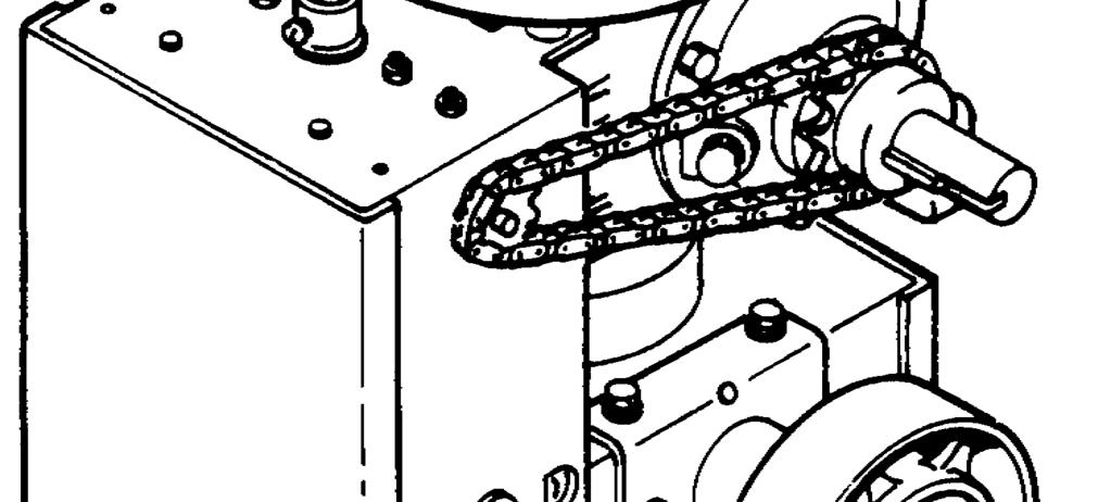
2 2 TABLE OF CONTENTS GJ Operator Features and Applications... 3 Preparation... 4 Figure 1 - Component Identification Pictorial... 4 Important Installation Warnings (Things To Do Before & During Installation)... 5 Table 1 - Component Identification Listing... 5 Door Types and Mounting Positions... 6 Installation Instructions... 7 Figures 5-9, Installation Pictorials... 8 Setting The Limits... 9 Electrical Wiring Instructions Figure 16 - Pneumatic Door Edge Installation Figure 17 - Field Wiring Operation and Adjustment Instructions Important Safety Instructions for Owner Wiring Terms Testing Maintenance Troubleshooting Warranty READ THESE STATEMENTS CAREFULLY AND FOLLOW THE INSTRUCTIONS CLOSELY! The Warning and Caution boxes throughout this manual are there to protect you and your equipment. Pay close attention to these boxes as you follow the manual. Indicates a MECHANICAL hazard of INJURY OR DEATH. Gives instructions to avoid the hazard. CAUTION Indicates a MECHANICAL hazard of DAMAGE to your operator or equipment. Gives instructions to avoid the hazard. Indicates an ELECTRICAL hazard of INJURY OR DEATH. Gives instructions to avoid the hazard. CAUTION Indicates an ELECTRICAL hazard of DAMAGE to your operator or equipment. Gives instructions to avoid the hazard. Registration Information-End User Copy Model Location Installed: Date Installed Address Serial # Address Address Installer s Information Company Name Company Address Company Address Company Address Company Telephone # Company Contact
3 PRODUCT FEATURES The purpose of this booklet is to provide assembly, installation and operation information concerning PowerMaster GJ Commercial Vehicular Garage Door Operators and related Accessory Products. NOTE: IT IS IMPORTANT THAT THIS INSTRUCTION MANUAL BE READ AND UNDERSTOOD COMPLETELY BEFORE INSTALLATION OR OPERATION IS ATTEMPTED. IT IS INTENDED THAT THE INSTALLATION OF THIS UNIT WILL BE DONE ONLY BY PERSONS TRAINED AND QUALIFIED IN THE INSTALLATION, ADJUSTMENT AND SERVICE OF COMMERCIAL OVERHEAD DOORS AND DOOR OPERATORS AND BY QUALIFIED ELECTRICIANS. NOTE: THE IMPORTANT SAFEGUARDS AND INSTRUCTIONS IN THIS MANUAL CANNOT COVER ALL POSSIBLE CONDITIONS AND SITUATIONS WHICH MAY OCCUR DURING ITS USE. IT MUST BE UNDERSTOOD THAT COMMON SENSE AND CAUTION MUST BE EXERCISED BY THE PERSON(S) INSTALLING, MAINTAINING AND OPERATING THE EQUIPMENT DESCRIBED HEREIN. DO NOT USE THIS EQUIPMENT FOR ANY OTHER APPLICATION THAN ITS INTENDED PURPOSE - OPERATING OVERHEAD COMMERCIAL VEHICULAR GARAGE DOORS. STANDARD FEATURES: Limit Switches: Rotary limit switches, easily adjusted over a wide range. The motor may be removed without affecting the limit switch adjustments. Manual Release: Permits manual operation of the door in the event of a power failure. Disengage operator by pulling chain and securing in wall mounted chain lock. MODEL GJ OPERATOR APPLICATIONS: GJ operators are intended for commercial and industrial use to raise or lower rolling steel or sectional overhead doors by chain coupling to the door shaft. GJ operators may also be used with roll up service doors and grilles when a chain hoist is not required.. A GJ operator DOES NOT LOCK THE DOOR IN ITS CLOSED POSITION. However, because the cross-header shaft is prevented by the operator from turning, the torsion springs provide no assistance in lifting the door should an attempt be made to raise it manually. GJ operators are used in the following applications: - Continuous Medium Duty Cycle Commercial installations. - Indoor Use Only - Use with foam/pneumatic reversing door edge or photoelectric device - REQUIRED where the 3-button station is out of sight of the door, or any other automatic, remote or manual control is used to activate the door. 3 Control Circuit: 24 Volts AC. Standard three button open, close and stop supplied. Will accept all standard control devices. Connections For Auxiliary Entrapment Protection Devices: Use with foam or pneumatic reversing door edge components or a photoelectric beam (across the opening). Momentary Contact To Close: Feature can be activated by simply moving a wire on the terminal strip. Constant Contact To Close: Standard operation. OPTIONAL FEATURES: Digital Radio Controls: Open, Close and Stop operation. Radio units are available to control up to 27 doors from one transmitter Digital Timer to Close: Adjustable from 0 to 17 minutes in one second intervals. Keyless Entry System: Connection terminals provided for hard wired keyless entry system. Optional radio receiver will allow operation of a wireless keyless system.
4 4 PREPARATION ELECTRIC DOOR OPENERS ARE DESIGNED FOR DOORS IN GOOD WORKING CONDITION, PROPERLY COUNTERBALANCED AND PROPERLY ADJUSTED IN ACCORDANCE WITH THE DOOR MANUFACTURER'S INSTALLATION INSTRUCTIONS. Before starting the installation of the operator, the door must be in good working condition and properly counterbalanced. Inspect the door and door guides for loose or missing hardware. Test the door manually for balance and ease of operation. Lubricate door hinges and rollers. If necessary, employ a qualified technician to adjust the springs for proper counterbalance of the door. Stops should be installed at the top end of each track to prevent the possibility of the door rollers moving beyond the ends of the track. If the cross header shaft is made from hollow tubing rather than solid rod, it is recommended that it be plugged with a short length of solid bar for a more secure installation of the shaft sprocket or flange coupler. Before removing the operator powerhead from the shipping carton, inspect the nameplate on the cover of the operator control box to verify that it is the correct model for the intended application and that the voltage and phase are in accordance with electrical power provided at the job site. Warning: Rope off the area to keep personnel and vehicles clear of the door and floor space in the vicinity of the operator during the installation. SPRINGS ARE SUBJECT TO VERY HIGH FORCES AT ALL TIMES AND ADJUSTMENTS MUST BE MADE ONLY BY A QUALIFIED PROFESSIONAL DOOR INSTALLER. REMOVE OR DISABLE ANY LOCKING DEVICES FROM DOOR AND REMOVE ALL ROPES.
5 IMPORTANT INSTALLATION NOTES 5 TO REDUCE THE RISK OF SEVERE INJURY OR DEATH: READ AND FOLLOW ALL INSTALLATION INSTRUCTIONS! Install only on a properly balanced garage door. An improperly balanced door could cause severe injury. Have a qualified service person make repairs to cables, spring assemblies and other hardware before installing the opener. Remove all ropes and remove or make inoperative all locks (unless mechanically and/or electrically interlocked to the power unit) that are connected to the garage door before installing the opener. Lightweight doors (fiberglass, aluminum etc.) must be reinforced to avoid door damage. Check the door manufacturer s instruction manual for a bracing procedure or the availability of a Reinforcement Kit. - The GJ Series Operator is a Commercial Vehicular Door Operator and as such is NOT recommended for pedestrian traffic. In installations where it is known that pedestrians will be nearby ensure a pedestrian door is available for entrance and exit to the building. In addition YOU MUST install an auxiliary entrapment protection device (reversing door edge or photoelectric beam device) as part of the complete operator system. - Connect an auxiliary entrapment protection device (reversing edge or photoelectric device across the door opening). A device of this type is STRONGLY ADVISED FOR ALL commercial operator installations. - An auxiliary entrapment protection device is REQUIRED when the three button control station is out of sight of the door or any other automatic or manual control is used. Install the opener at least 8 feet or more above the floor. Do not connect the opener to the source of power until instructed to do so. Locate the control station: a) within sight of the door and; b) at a minimum height of five feet above the floor and; c) away from all moving parts of the door. Do not overtighten the clutch adjustment (when provided) to compensate for a poorly working door. Securely attach any signs or placards to either the door or above the control station as directed (see page 10). After installing the opener, all control features must be tested for proper operation (see page 13). TABLE 1 - COMPONENT IDENTIFICATION LISTING Item # Description Qty. 1 Operator Power Head 1 2 Driven Sprocket on Door Shaft 1 3 Set Screw, 5/16-18 x 1, Square Head 2 4 Steel Square Key 1 5 Drive Chain 1 6 Master Link Button Station 1 8 Mounting Bracket (optional) 1
6 6 DOOR TYPES & MOUNTING POSITIONS Figure 3
7 INSTALLATION INSTRUCTIONS 7 SPRINGS, PULLEYS, CABLES AND MOUNTING HARDWARE USED TO BALANCE YOUR GARAGE DOOR ARE UNDER EXTREME TENSION AT ALL TIMES AND CAN CAUSE SEVERE INJURY OR DEATH IF DISTURBED. DO NOT ATTEMPT ADJUSTMENT. MOUNTING THE OPERATOR: WHEN PREPARING THE MOUNTING SURFACE ENSURE THE OPERATOR WILL BE RIGID AND SECURE WHEN INSTALLED, THE MOUNTING SURFACE WILL PROVIDE A LEVEL BASE, AND THE OPERATOR S DRIVE SHAFT WILL BE PARALLEL WITH THE DOOR SHAFT. FAILURE TO MEET THESE CONDITIONS WILL RESULT IN AN OVERALL UNSAFE DOOR OPERATION AND PREMATURE FAILURE OF THE DOOR AND DOOR OPERATOR. 1. Figures 2 and 3, page 6 illustrates several positions suitable for mounting the operator; right hand or left hand wall mount or horizontal (shelf) mount to the torsion shaft. For sectional doors, the GJ operator must be wall mounted. For rolling steel doors the operator may be wall mounted or hood mounted by using an optional hood mounting bracket, [9]. NOTE: THE OPERATOR IS BUILT FOR RIGHT OR LEFT HAND INSTALLATION AS ORDERED. DO NOT ATTEMPT TO CHANGE HAND OF OPERATOR IN THE FIELD. 2. Determine location and mounting for the unit. Install the driven sprocket on the door shaft with key (4) and set screw (3). Do not tighten the set screws at this time. If the door shaft lacks a keyway you will need to drill and pin the sprocket in accordance with Step 6. The sprocket should be kept as close as possible to the bearing. Fasten the wall mounting plate or the mounting bracket (if applicable ) to the operator gear box base. Temporarily suspend the operator in its mounting position so that the distance between the door shaft and the operator s output shaft is between 12 and 15. See Figure 5 for wall mount and Figure 6 for bracket plate mount illustration. The distance between the shafts may be greater if the mounting conditions prohibit installation as suggested. 3. Connect the operator drive sprocket [and the door sprocket with the drive chain [5] and connecting link [6], shortening the chain to the proper length if necessary. To shorten the chain use a chain break tool or drive out the appropriate rivets with a punch. 4. With the chain tight and straight and the operator s output shaft parallel with the door shaft, trace the mounting slots (holes) on the mounting surface then lower the operator to the floor. The GJ operator gear box mounting hole pattern is shown in Figure The operator should be installed using 3/8 bolts through the wall. If the building s construction will not allow the usage of through bolts then use lag bolts and shields (or the equivalent type fasteners). Mount the operator, slipping the drive chain on before bolting the operator to the mounting surface but do not completely tighten the bolts at this time. 6. Re-align the door shaft and operator drive shaft sprockets and connecting drive chain. Secure the door sprocket in place with the set screws. If no keyway exists in the door shaft, drill a 3/8 diameter hole through the door sprocket and door shaft with the sprocket in its aligned position. Insert a 3/8 diameter bolt (not provided) through the sprocket hub and shaft. Secure with a lock washer and hex nut. See Figure Adjust the drive chain tension such that there is no more than 1/4 slack when the chain is depressed between the sprockets. See Figure 8. The preferred mounting is with the motor end up and the operator below the door shaft. This results in better clearance for the hand chain and disconnect chain. 2 Figure 4 4-1/2


8 8 INSTALLATION INSTRUCTIONS 12 to 15 Figure 6 12 to 15 Figure 5 Figure 8
9 9 INSTALLATION INSTRUCTIONS TO AVOID RISK OF ENTRAPMENT AND POSSIBLE DAMAGE TO THE DOOR AND OPERATOR THE LIMITS MUST BE ADJUSTED BEFORE APPLYING POWER TO THE OPERATOR. SETTING THE LIMIT SWITCHES 1. Open the cover on the electrical enclosure. There are two limit nuts on the threaded shaft that move laterally along the shaft as the operator opens and closes the door. When a limit nut nears the end of the shaft it activates a (set of) switch(es). The OPEN limit switch is on the LEFT and the CLOSE limit switch is on the RIGHT. Auxiliary switches may also be present, they are used to control other functions. These are mounted to a separate bracket and should not be confused with the the OPEN and CLOSE Limit Switches which are mounted to the back of the electrical enclosure box and are somewhat hidden from view. 2. Manually raise the door to a nearly open position. 3. Depress the limit nut retaining bracket away from the slots in the limit nuts. Turn the OPEN limit nut on the shaft until it engages the Open Limit Switch, the switch will sound an audible click when engaged. If the Open Limit is a DPDT switch (a total of 6 (six) connecting terminals protruding from the switch body, a SPDT switch has only three (3) terminals), you will need to listen for two audible clicks. Release the retaining bracket and be sure that it engages in slots of both limit nuts. 4. Manually lower the door to a nearly closed position and repeat Step #3 with the Close limit nut and switch. 5. If auxiliary switches are present, the limit nut will actuate them just prior to activating the open or close limit switch. (This is preset at the factory.) 6. Manually move the door to a half open position to avoid door damage due to incorrect power supply phasing. On three phase units the door may initially run in the wrong direction when power is first applied. With the door in a mid position there will be time to stop the door before damage can happen if incorrect phasing occurs. 7. A final limit adjustment will be necessary after the connection of the power supply in order to ensure the door stops at the proper Open and Close positions. Figure 13
10 ELECTRICAL WIRING INSTRUCTIONS 10 TO PREVENT THE RISK OF PERSONAL INJURY OR DEATH : DISCONNECT POWER AT THE FUSE BOX BEFORE PROCEEDING. ELECTRICAL CONNECTIONS MUST BE MADE BY A QUALIFIED INDIVIDUAL. OBSERVE LOCAL ELECTRICAL CODES WHEN WIRING THE OPERATOR. NOTE: PowerMaster operators have been designed and constructed for use with voltages from 115 Volts AC to 480 Volts AC, in single or three phase. Check the operator nameplate label on the control box cover for the proper voltage and phase. The application of an improper input voltage or phase will result in catastrophic failure to the internal electrical components. Observe local electrical codes when wiring the operator. When hard wiring, observe state and local electrical codes. A wiring diagram is attached to the inside of the control box cover. Connect the appropriate voltage and phase power leads to the appropriate terminals as per the wiring diagram and connect a ground wire to the grounding screw. On three phase units, incorrect phasing of the power supply will cause the motor to rotate in the wrong direction (open when CLOSE button is pushed and vice versa). To correct this, interchange any two of the incoming three phase conductors. The wiring diagram attached inside the cover of the control box details all of the field wiring terminal connections for the operator. Always connect the wires to the push-button controls and auxiliary devices exactly as shown. Warning: Control voltage of the operator is 24 volts AC, Class 2. Do not run the power leads and control circuit wiring in the same electrical conduit. TO PREVENT THE RISK OF PERSONAL INJURY AND/ OR DAMAGE TO DOOR OR PROPERTY, ONLY OPERATE DOOR CONTROL WHEN DOOR IS IN CLEAR VIEW. IF CONTROL STATION CANNOT BE LOCATED WHERE THE DOOR IS VISIBLE OR IF ANY OTHER DEVICE IS USED TO CONTROL THE DOOR AN AUXILIARY ENTRAPMENT DEVICE (DOOR EDGE OR PHOTOELECTRIC) MUST BE CONNECTED. RISK OF ENTRAPMENT THAT MAY RESULT IN SERIOUS PERSONAL INJURY OR DEATH. DISCONNECT POWER TO THE OPENER BEFORE AND DURING INSTALLATION OF AN ACCESSORY REVERSING DOOR EDGE OR PHOTOELECTRIC DEVICE. DO NOT RECONNECT POWER TO OPENER UNTIL INSTRUCTED TO DO SO. ENSURE DOORWAY IS CLEAR BEFORE STARTING TESTING OF UNIT. Note: PowerMaster operators are pre-wired to accept reversing edge components. To comply with UL requirements, one of these systems must be installed and wired to the operator. Refer to Figures 16 and 17 for Edge component wiring and installation. For operator models not installed with reversing edge components or photoelectric device, ONLY ONE THREE BUTTON STATION OR A CONTROL WIRED FOR CONSTANT PRESSURE TO CLOSE MAY BE USED TO CONTROL THE OPERATOR. THIS IS TO COMPLY WITH UL SAFETY REQUIREMENTS. IN THIS CASE THE CONTROL STATION MUST BE LOCATED WITHIN CLEAR SIGHT OF THE DOOR ADJACENT TO A PLACARD (SUPPLIED WITH THE OPERATOR) WITH THIS WORDING: TO PREVENT ENTRAPMENT DO NOT START DOOR DOWNWARD UNLESS DOOR WAY IS CLEAR Operators which are equipped with a reversing edge circuit may have one or more additional means of control which should be wired in accordance with the diagram supplied in the operator. Refer to Figure 17. Number 18 gauge wire or heavier must be used for wiring the control stations and auxiliary control devices to the operator. Smaller gauge wire will cause operational problems, especially when multiple pushbutton stations are used or during summer months. CAUTION TO AVOID DAMAGE TO DOOR AND OPERATOR ENSURE ALL DOOR LOCKS ARE DISABLED. USE AN INTERLOCK SWITCH IF A LOCK IS REQUIRED TO RETAIN FUNCTIONALTY.
11 11 PNEUMATIC DOOR EDGE INSTALLATION - FIELD WIRING Figure OR NOTES: SINGLE CONTACT CONTROL 1 BR ST OP EXT'L INTL'K (WHEN REQ'D) 2-WIRE EDGE OR AIRSWITCH (SEE NOTE #3) PHOTOCELL OR 3-WIRE AIRSWITCH 1 - INSTALL BROWN JUMPER WIRE IF THERE IS NO STOP BUTTON OR EXTERNAL INTERLOCK SWITCH CONNECTED TO TERMINAL STRIP. 2 - REMOVE VIOLET JUMPER WIRE WHEN TIMER DEFEAT SWITCH IS USED. 3 - INTERNAL ORANGE JUMPER. -MOVE THIS JUMPER FROM TERMINAL #7 TO #8 IF ALL OBSTRUCTIONS SENSORS ARE 2-WIRE TYPE. -REMOVE JUMPER IF 3-WIRE DEVICES ARE USED. 4 -TREADLES, PULL SWITCHES, KEY SWITCHES, PHOTO-ELECTRIC DEVICES, ETC. MAY BE CONNECTED TO TERMINALS INDICATED. 5 -REMOTE CONTROL UNITS (EXCLUDING TREADLES AND PHOTO-ELECTRIC UNITS). PULL SWITCHES AND SINGLE CONTACT CONTROL STATIONS MAY BE CONNECTED TO TERMINALS INDICATED. CL FIGURE 17 V TIMER DEFEAT SWITCH (N.C.) (WHEN REQ'D) OBSTRUCTION SENSING DEVICE 2 GND L1 L2 L3 INCOMING LINE R3 R2 R1 RADIO RCVR
12 OPERATION AND ADJUSTMENT INSTRUCTIONS 12 IMPORTANT SAFETY INSTRUCTIONS FOR OWNER TO REDUCE THE RISK OF SEVERE INJURY OR DEATH: READ AND FOLLOW ALL INSTRUCTIONS! NEVER let children operate or play with door controls. Keep the Remote Control away from children. ALWAYS keep a moving door in sight and keep people and objects away from the door area until the door is completely closed. NO ONE SHOULD CROSS THE PATH OF A MOVING DOOR. TEST THE DOOR OPENER S REVERSING FEATURE (where applicable) MONTHLY. The door MUST reverse upon contact with a 4 high object on the floor. After adjusting the force setting, if equipped with a clutch, or the limit of travel, ALWAYS RETEST the Opener. Failure to ADJUST THE OPENER PROPERLY may result in SERIOUS INJURY OR DEATH. DO NOT over adjust the force setting (clutch, where applicable) to compensate for a poorly working door. See page 19 for procedure to check the door operation and insert sheet for proper clutch adjustment. KEEP THE GARAGE DOOR PROPERLY BALANCED. (See the door owner's manual.) AN IMPROPERLY BALANCED DOOR MAY CAUSE SEVERE INJURY OR DEATH. Have a QUALIFIED SERVICE PERSON MAKE REPAIRS TO CABLES, SPRING ASSEMBLIES AND OTHER HARDWARE. SAVE THIS INSTRUCTION MANUAL AND GIVE TO THE END USER. NOTE: It is now necessary to turn on the power in order to run the Opener to check for proper operation and limit settings. Before doing so, ensure that all mounting hardware are installed and properly tightened, that all electrical connections are per local code requirements, and that proper wiring practices have been followed. Also, double-check that all ropes have been removed from the door and that the doorway is clear. FAILURE TO TEST REVERSING SYSTEM COULD RESULT IN DEATH OR SERIOUS INJURY. TEST THIS SYSTEM ONCE A MONTH. AVOID ELECTROCUTION: DO NOT ROUTE LOW VOLTAGE WIRES IN SAME CONDUIT AS HIGH VOLTAGE WIRES. FOLLOW ALL LOCAL ELECTRICAL CODES or THE NATIONAL ELECTRICAL CODE (NEC). WIRING TERMS MOMENTARY CONTACT: Button can be pushed and then released and door will keep moving or stop without maintaining pressure on the button. CONSTANT PRESSURE: Constant pressure is required on the button in order for continued door movement. When the button is released the door will stop and possibly reverse to full open depending on wiring type. DOOR EDGE/PHOTOELECTRIC INPUT: The operator wiring provides for input from an optional pneumatic or electric door bottom edge or photoelectric device that will cause a closing door to stop and may reverse it to open depending on the wiring type.
13 13 OPERATION AND ADJUSTMENT INSTRUCTIONS TESTING ALWAYS DISCONNECT POWER TO THE OPERATOR BEFORE SERVICING, CONNECTING ACCESSORY DEVICES OR MAKING ADJUSTMENTS. Following installation, the operator MUST be tested and respond correctly to all controls as specified on the wiring diagram. KEEP personnel and equipment clear of the area beneath the door when performing the tests. When testing the 3-button wall station, first observe that each button operates the door in the direction indicated and that the STOP button performs that function. With the door stopped at its full open position, the OPEN button should be inoperative. This should be verified and, likewise, the CLOSE button should be inoperative with the door fully closed. Certain operator control circuits use only a single button or a two button control station and may be designed to function differently than the more common three-button circuit described above. Test the controls in accordance with the proper response for your installation. Observe the door when traveling in each direction for smoothness of operation. Test the setting of the clutch (if equipped) by restraining the door by hand. The clutch should slip. Re-check the limit settings. The door should close tightly at the floor without excessive impact. Likewise, it should fully clear the door opening without the carrier striking the stops on the rail. GJ operators are equipped with a reversing edge circuit for use with pneumatic edge or foam edge door components. DO NOT STAND UNDER DOOR TO TEST REVERSING EDGE. USE A CORRUGATED BOX OR SIMILAR OBJECT. To test it for proper reversal, place an object beneath the leading edge of the door. The door should instantly reverse when it comes into contact with the object provided the height of the object exceeds the cut out point built into the close limit switch (approximately four inches). If the operator is equipped with other means of control, such as additional 3 button stations or radio controls, each of these should be tested separately for proper operation. To test the manual disconnect first move the door to the fully closed position. Then disconnect the power to the operator. Manual door operation mode should engage when the release chain is pulled. The door can then be manually opened or closed by physically moving the door. If it is difficult to engage and/or the jackshaft to doorshaft chain appears to be under compression, reset the CLOSE limit slightly to reduce the door travel in the close direction.
14 MAINTENANCE 14 Normally, very little maintenance is required. A monthly visual inspection must be made for loose or missing hardware and for excessive slack in the jackshaft chain. Test the reversing edge circuit or components (where applicable) at least once a month by permitting the door to contact an obstruction while closing. DO NOT STAND UNDER DOOR TO TEST REVERSING EDGE. USE A CORRUGATED BOX OR SIMILAR OBJECT. Periodic inspection of gear box oil level should be made. If oil level is below 1/2 full, add Mobil 1 Gear Oil or equivalent to bring level to 1/2 full. Lubrication of the operator is not required. It is important, for trouble free service from the operator, that the door be kept free from binding, properly counter balanced and periodically lubricated. An annual inspection of the door by a qualified overhead door professional is recommended. *Door must be in good operating condition. An electrical door operator cannot move a garage door that is in poor condition. The door must operate freely in the track, with no binding or obstructions, and must be well balanced. Check the spring balance of your door by manually bringing the door to a half-open position and leaving it there. If the door stays in that position, it is well balanced. If it moves more than a few inches the springs possibly need adjustment. Call a qualified door service company. Warning: Repairs and adjustments to the door and operator should be performed only by someone qualified to service commercial overhead doors and operators.
15 15 TROUBLE SHOOTING SYMPTOM Motor runs but door does not move Limit switches do not hold setting POSSIBLE CAUSE Door jammed or obstructed. Sprocket key missiing Disconnect engaged Drive chain too loose; permits chain to jump teeth Limit nuts binding on screw, causing them to jump position on retaining bracket. SOLUTION Check manual operation of door. Check door sprocket. Release disconnect chain from chain lock. Adjust chain to proper tension. See Figure 7. Check for free rotation on limit screw. Lubricate screw or replace nuts if threads are defective. Limit nut retaining bracket not engaging notches in nuts. Set nuts and be sure bracket is in notch on each nut. (See Figure 13. Door drifts when operator shuts off. Limit sprocket loose Door tension incorrect. Check set screws Disconnect operator and check operation of door. Motor hums does not run. Dead phase (3 Phase). Check power supply. Centrifugal Switch (1 Phase) Lubricate switch or change motor *Door locked or jammed. Check door. Try manual operation. Motor does not run when open or close wall button is pressed. Building fuse blown or circuit breaker tripped. Overload protector tripped. Check power supply fuses, circuit breakers, disconnect switch, check for cause. Reset and check for cause. NOTE: To isolate cause, operate contactor solenoid plunger manually. If motor runs, cause is in push button circuit. Check pushbutton circuits. Check push button wiring. Check transformer for 24volt output. For technical support call Operator closes door when open button is pressed, and limit switches do not function properly. On three phase operators power supply is connected out of phase. Operator not installed correctly. Interchange connections of any two power supply leads. (See wiring diagram) Remount operator so that motor is up or toward door wall or contact factory as to wiring changes required. Operator fails to shut off at fully open closed position. On three phase operators power supply is connected out of phase. Check phase as above. Limit nuts not adjusted See limit adjustments page 9. Defective limit switch. Operate limit switch manually while door is moving to determine if switch is operative. Single phase operator (without instant reverse motor). Stuck push button or short in control wiring. Limit drive chain broken or inoperative. If door overrides up limit, check down button and circuit. If door overrides down limit, check open button and circuit. Replace chain, check limit sprocket set screws for tightness.
16 PowerMaster Limited 2-Year Warranty PowerMaster warrants all door operators to be free of defects in materials and workmanship for a period of two (2) years from date of purchase. If any part is found to be defective during this period, new parts will be furnished free of charge. Failure of this product due to misuse, improper installation, alterations, vandalism, or lack of maintenance is not covered under this warranty, and voids any other implied warranties herein. PowerMaster is not responsible for any labor charges incurred in connection with the installation of warranted parts. In order to activate this warranty, the registration form below MUST be completed and returned within THIRTY CALENDAR DAYS FROM DATE OF PURCHASE via certified mail, fax ( ) or via to pmtech@optonline.net. If registration is not activated, a one-year warranty will apply. Model Serial # Date Installed Company Name Address Address 2 City, State, Zip Telephone # Contact Name Installer s Information
17 Need Technical Support? Visit: Call us toll us: PMtech@VEpower.net
MODEL MG Gearhead Operator
 INSTALLATION AND OWNER S MANUAL MODEL MG Gearhead Operator UL 325 and UL 991 Listed Serial #: Date Installed: Your Dealer: READ THIS MANUAL CAREFULLY BEFORE INSTALLATION OR USE. SAVE THESE INSTRUCTIONS.
INSTALLATION AND OWNER S MANUAL MODEL T Trolley Operator
 INSTALLATION AND OWNER S MANUAL MODEL T Trolley Operator Serial #: Date Installed: Your Dealer: READ THIS MANUAL CAREFULLY BEFORE INSTALLATION OR USE. SAVE THESE INSTRUCTIONS. As of date of manufacture,
INSTALLATION AND OWNER S MANUAL MODEL T Trolley Door Operator
 INSTALLATION AND OWNER S MANUAL MODEL T Trolley Door Operator UL 325 and UL 991 Listed Serial #: Date Installed: Your Dealer: READ THIS MANUAL CAREFULLY BEFORE INSTALLATION OR USE. SAVE THESE INSTRUCTIONS.
INSTALLATION AND OWNER S MANUAL M50JF & M50JH M-SERIES JACKSHAFT COMMERCIAL VEHICULAR DOOR OPERATORS
 INSTALLATION AND OWNER S MANUAL M50JF & M50JH M-SERIES JACKSHAFT COMMERCIAL VEHICULAR DOOR OPERATORS 100771 As of date of manufacture, meets all ANSI/UL 325 Safety Requirements for Vehicular door operators
MODEL JH JACKSHAFT INDUSTRIAL DOOR OPERATOR INSTALLATION MANUAL. OPERATOR SPECIALTY COMPANY, INC. P.O. Box 128 Casnovia, MI 49318
 MODEL JH JACKSHAFT INDUSTRIAL DOOR OPERATOR INSTALLATION MANUAL OPERATOR SPECIALTY COMPANY, INC. P.O. Box 128 Casnovia, MI 49318 OSCO requires the use of a reversing edge or photoelectric control for pedestrian
MJ & MH M-S SERIES JACKSHAFT COMMERCIAL VEHICULAR DOOR OPERATORS with SOLID STATE CONTROLS
 USA & Canada (800) 421-1587 & (800) 392-0123 (760) 438-7000 Toll Free FAX (800) 468-1340 www.linearcorp.com INSTALLATION AND OWNER S MANUAL MJ & MH M-S SERIES JACKSHAFT MERCIAL VEHICULAR DOOR OPERATORS
MO-S SERIES MO-S SERIES SOLID STATE COMMERCIAL
 USA & Canada (800) 421-1587 & (800) 392-0123 (760) 438-7000 Toll Free FAX (800) 468-1340 www.linearcorp.com INSTALLATION AND OWNER S MANUAL MO-S SERIES MO-S SERIES SOLID STATE MERCIAL VEHICULAR DOOR As
Model JG Industrial Gearhead Jackshaft Door Operator Safety, Installation, and Service Manual
 Model JG Industrial Gearhead Jackshaft Door Operator Safety, Installation, and Service Manual OSCO requires use of an electric edge or photoelectric control for pedestrian protection on all automatic or
INSTALLATION INSTRUCTIONS AND OPERATION MANUAL
 INSTALLATION INSTRUCTIONS AND OPERATION MANUAL UL325-2010 Compliant Commercial and Industrial Door Operator Logic Control Continuous Duty IMPORTANT INSTALLATION INSTRUCTIONS WARNING To reduce the risk
INSTALLATION INSTRUCTIONS AND OPERATION MANUAL
 INSTALLATION INSTRUCTIONS AND OPERATION MANUAL Cornell RG Operator RGRL Series (w/ Internal Interlock sensor) ES 10-288 GENERAL NOTES TO REDUCE THE RISK OF SEVERE INJURY OR DEATH, READ AND FOLLOW ALL INSTALLATION
PowerMaster MODEL MBG. Installation Manual U L R UL 325 AND UL 991 LISTED MEDIUM DUTY BARRIER GATE OPERATOR TABLE OF CONTENTS
 PowerMaster TABLE OF CONTENTS MODEL MBG MEDIUM DUTY BARRIER GATE OPERATOR Important Safety Information...... 3 System Designer Safety Instructions.......4 Installer Safety Instructions....... 5 Installation
INSTALLATION INSTRUCTIONS AND OPERATION MANUAL
 INSTALLATION INSTRUCTIONS AND OPERATION MANUAL - 1/3, 1/2, 3/4hp UL325-2010 Compliant Commercial and Industrial Door Operator Logic Control Duty Cycle 20 Cycles per Hour IMPORTANT INSTALLATION INSTRUCTIONS
INSTALLATION INSTRUCTIONS AND OPERATION MANUAL
 INSTALLATION INSTRUCTIONS AND OPERATION MANUAL FS Series Rolling Fire Door Operators CORPORATION GENERAL NOTES TO REDUCE THE RISK OF SEVERE INJURY OR DEATH, READ AND FOLLOW ALL INSTALLATION INSTRUCTIONS
INSTALLATION AND OWNER S MANUAL
 (800) 878-7829 sales@commercialdooroperators.com www.commercialdooroperators.com INSTALLATION AND OWNER S MANUAL GT MODEL GT-S SERIES DRAWBAR MERCIAL VEHICULAR DOOR OPERATORS with SOLID STATE CONTROLS
INSTALLATION INSTRUCTIONS AND OPERATION MANUAL
 INSTALLATION INSTRUCTIONS AND OPERATION MANUAL FS Series Rolling Fire Door Operators UL325-2010 Compliant Restricted Duty Operators CORPORATION IMPORTANT INSTALLATION INSTRUCTIONS WARNING To reduce the
INSTALLATION AND OWNER S MANUAL
 USA & Canada (800) 421-1587 & (800) 392-0123 (760) 438-7000 Toll Free FAX (800) 468-1340 www.linearcorp.com INSTALLATION AND OWNER S MANUAL T MODEL T-S SERIES DRAWBAR MERCIAL VEHICULAR DOOR OPERATORS with
COOKSON OWNER'S MANUAL
 COOKSON OWNER'S MANUAL FDO-A10 INDUSTRIAL DUTY FIRE DOOR OPERATOR R L I S T E D 3040233 US CONTROL PANEL SERIAL# OPERATOR SERIAL# 9001.DWG ECN 0959 REV 4 SPECIFICATIONS MOTOR TYPE:...INTERMITTENT HORSEPOWER:...1/8
INSTALLATION INSTRUCTIONS AND OPERATION MANUAL
 INSTALLATION INSTRUCTIONS AND OPERATION MANUAL NEMA 4X UL325-2010 Compliant Commercial and Industrial Door Operator Logic Control Continuous Duty IMPORTANT INSTALLATION INSTRUCTIONS WARNING To reduce the
MODEL D-SBG Single Arm Barrier Gate Operator
 INSTALLATION AND OWNER S MANUAL MODEL D-SBG Single Arm Barrier Gate Operator UL 325 and UL 991 Listed WITH NITRO BOARD (SEE SUPPLEMENTAL MANUAL) Serial #: Date Installed: Your Dealer: READ THIS MANUAL
INSTALLATION INSTRUCTIONS AND OPERATION MANUAL
 INSTALLATION INSTRUCTIONS AND OPERATION MANUAL - 1/3, 1/2, 3/4hp UL325-2010 Compliant Commercial and Industrial Door Operator Logic Control Duty Cycle 20 Cycles per Hour IMPORTANT INSTALLATION INSTRUCTIONS
INSTALLATION INSTRUCTIONS AND OPERATION MANUAL
 INSTALLATION INSTRUCTIONS AND OPERATION MANUAL Commercial and Industrial Fire Door Operator Logic Control Restricted Duty Fire Door Operators IMPORTANT INSTALLATION INSTRUCTIONS WARNING To reduce the risk
AUD INSTALLATION AND OWNER S MANUAL AU-S SERIES WITH SOLID STATE CONTROL CIRCUITRY DRAWBAR COMMERCIAL VEHICULAR DOOR OPERATORS
 USA & Canada (800) 421-1587 & (800) 392-0123 (760) 438-7000 Toll Free FAX (800) 468-1340 www.linearcorp.com INSTALLATION AND OWNER S MANUAL AUD AU-S SERIES WITH SOLID STATE CONTROL CIRCUITRY DRAWBAR MERCIAL
MODEL D-WBG Wishbone Arm Barrier Gate Operator
 INSTALLATION AND OWNER S MANUAL MODEL D-WBG Wishbone Arm Barrier Gate Operator UL 325 and UL 991 Listed WITH NITRO BOARD (SEE SUPPLEMENTAL MANUAL) Serial #: Date Installed: Your Dealer: READ THIS MANUAL
INSTALLATION AND OWNER S MANUAL AUD-S AU SERIES WITH SOLID STATE CONTROL CIRCUITRY DRAWBAR COMMERCIAL VEHICULAR DOOR OPERATORS
 INSTALLATION AND OWNER S MANUAL AUD-S AU SERIES WITH SOLID STATE CONTROL CIRCUITRY DRAWBAR MERCIAL VEHICULAR DOOR OPERATORS 107093 As of date of manufacture, meets all ANSI/UL 325 Safety Requirements for
EXTREME R MOTOR OWNER'S MANUAL
 EXTREME R MOTOR OWNER'S MANUAL 2 HP, 3 HP & 5 HP WITH SELF-ENGAGING CHAIN HOIST FOR TECHNICAL SUPPORT PLEASE CALL 1-(855) 594-4969 3137B(0) ECN 1313 BY JM 7/9/15 OPERATOR SERIAL# PRO-FDG MOTOR OPERATORS
INSTALLATION INSTRUCTIONS AND OPERATION MANUAL
 INSTALLATION INSTUCTIONS AND OPEATION MANUAL FS-50 Series olling Fire Door Operators UL325-200 Compliant estricted Duty Operators COPOATION 3-3966-02(0) BY G ECN 5 5/9/ 2/0 IMPOTANT INSTALLATION INSTUCTIONS
Model 1550 Single Swing Gate Model 1650 Dual Swing Gate
 Gate Operators, Inc. Model 1550 Single Swing Gate Model 1650 Dual Swing Gate Swing Gate Operator CONTENTS Safety Precautions... 2 Applications... 3 Pre-Installation Checklist... 4 Parts Identification...
INSTALLATION M ANUAL
 INSTALLATION MANUAL Table of Contents UL Listings Installing the Warning Sign / Precautions Methods of Installation / Compact Installation Mounting the Secondary Entrapment / Welding Gate Arn Mounting
ControlHoist Standard
 ControlHoist 2.0 STANDARD INSTALLATION INSTRUCTIONS AND USER GUIDE ControlHoist Standard Models CSJ & CSH Industrial Duty BELT DRIVE Jackshaft Jackshaft with Chain Hoist Special Application Jackshaft -NOT
SAFE AND SECURE EXTREME R MOTOR OWNER'S MANUAL MODEL PRO-FDG FOR TECHNICAL SUPPORT PLEASE CALL 1-(855) OPERATOR SERIAL#
 OPERATOR SERIAL#") SAFE AND SECURE EXTREME R MOTOR OWNER'S MANUAL MODEL PRO-FDG FOR TECHNICAL SUPPORT PLEASE CALL 1-(855) 594-4969 3121B(4) ECN 1288 BY TG 2/6/15 OPERATOR SERIAL# PRO-FDG MOTOR OPERATORS MOTOR OWNER'S MANUAL
SAFE AND SECURE EXTREME R MOTOR OWNER'S MANUAL MODEL PRO-FDG FOR TECHNICAL SUPPORT PLEASE CALL 1-(855) 594-4969 3121B(4) ECN 1288 BY TG 2/6/15 OPERATOR SERIAL# PRO-FDG MOTOR OPERATORS MOTOR OWNER'S MANUAL
Gate Operators, Inc. Model 7100UL Residential & Medium Duty Commercial Slide Gate Operator INSTALLATION MANUAL
 Gate Operators, Inc. Model 7100UL Residential & Medium Duty Commercial Slide Gate Operator INSTALLATION MANUAL 10-04-00 CONTENTS Safety Precautions... 2 Applications... 3 Pre-Installation Checklist...
Model H/HB Heavy-Duty Industrial Drawbar Door Operator Safety, Installation and Service Manual
 Model H/HB Heavy-Duty Industrial Drawbar Door Operator Safety, Installation and Service Manual OSCO requires use of an electric edge or photoelectric control for pedestrian protection on all automatic
MODEL WBG WISHBONE BARRIER GATE OPERATOR
 TABLE OF CONTENTS MODEL WBG WISHBONE BARRIER GATE OPERATOR Important Safety Information.....3 System Designer Safety Instructions.......4 Installer Safety Instructions........ 5 End User Safety Warnings...-
APOLLO Gate Operators, Inc.
 APOLLO Gate Operators, Inc. Model 3500ETL/3600ETL Commercial Swing Gate Operator INSTALLATION MANUAL 01/08 CONTENTS IMPORTANT SAFETY INSTRUCTIONS. 3 Applications... 4 Pre-Installation Checklist... 5 Parts
MODEL MSW Medium Duty Swing Gate Operator
 INSTALLATION AND OWNER S MANUAL MODEL MSW Medium Duty Swing Gate Operator UL 325 and UL 991 Listed 22-1/4 16-1/2 19-1/2 16 20'' LENGTH X 14-3/4'' WIDTH 2 O.D. PIPE (BY OTHERS) Serial #: Date Installed:
PowerMaster. Installation Manual UL 325 AND UL 991 LISTED MODEL RSG TABLE OF CONTENTS
 MODEL RSG RESIDENTIAL SLIDE GATE OPERATOR TABLE OF CONTENTS PowerMaster Installation Manual RESIDENTIAL SLIDE GATE OPERATOR UL 325 AND UL 991 LISTED UL R Important Safety Information.....3 UL Installation
INSTALLATION INSTRUCTIONS AND OPERATION MANUAL
 INSTALLATION INSTRUCTIONS AND OPERATION MANUAL SDCL-5025 UL325-2010 Compliant Commercial and Industrial Door Operator Logic Control Duty Cycle 10 Cycles per Hour IMPORTANT INSTALLATION INSTRUCTIONS To
COOKSON OWNER S MANUAL
 COOKSON OWNER S MANUAL ELECTRIC CLUTCH RELEASE FOR TUBULAR MOTOR 3117(1) ECN 0951 BY RG 10/28/10 1 PATENT NO. 6,155,324 SPECIFICATIONS ELECTRICAL SPECIFICATIONS TUBULAR MOTOR FOR TUBULAR MOTOR ELECTRICAL
ControlHoist Standard
 ControlHoist 2.0 INSTALLATION INSTRUCTIONS AND USER GUIDE ControlHoist Standard Model CST STANDARD Industrial Duty BELT DRIVE Trolley -NOT FOR RESIDENTIAL USE- -FOR INDOOR USE ONLY- IMPORTANT: PLEASE READ
OWNER S MANUAL MODEL NO. MEDIUM DUTY JACK SHAFT OPERATOR MDJ, MDJH, MDJB, MDJBH READ AND FOLLOW ALL INSTALLATION INSTRUCTIONS SAVE THESE INSTRUCTIONS
 OWNER S MANUAL MEDIUM DUTY JACK SHAFT OPERATOR MODEL NO. NOT FOR RESIDENTIAL USE READ AND FOLLOW ALL INSTALLATION INSTRUCTIONS SAVE THESE INSTRUCTIONS This unit is intended for limited duty applications
HAZARDOUS (NEMA 7/9) INDUSTRIAL DUTY COMMERCIAL DOOR OPERATOR 2 YEAR WARRANTY. Serial # Box. Installation Date. Wiring Type
 INDUSTRIAL DUTY COMMERCIAL DOOR OPERATOR 2 YEAR WARRANTY. Serial # Box. Installation Date. Wiring Type") O W N E R S M A N U A L HAZARDOUS (NEMA 7/9) INDUSTRIAL DUTY COMMERCIAL DOOR OPERATOR 2 YEAR WARRANTY Serial # Box Installation Date Wiring Type TABLE OF CONTENTS SPECIFICATIONS Operator Dimensions.................................
O W N E R S M A N U A L HAZARDOUS (NEMA 7/9) INDUSTRIAL DUTY COMMERCIAL DOOR OPERATOR 2 YEAR WARRANTY Serial # Box Installation Date Wiring Type TABLE OF CONTENTS SPECIFICATIONS Operator Dimensions.................................
MODEL SG & DSG Slide Gate Operator UL 325 and UL 991 Listed
 INSTALLATION AND OWNER S MANUAL MODEL SG & DSG Slide Gate Operator UL 325 and UL 991 Listed 27 14-1/2 34 3 O.D. POST 15-5/8 16-3/4 22 8" Serial #: Date Installed: Your Dealer: READ THIS MANUAL CAREFULLY
LMPLC COOKSON OWNER'S MANUAL FDO A & B SOLID STATE INDUSTRIAL DUTY FIRE DOOR OPERATOR. B2/C2 Wiring 2 YEAR WARRANTY FDO 1/2 HP FDO A & B
 COOKSON OWNER'S MANUAL FDO A & B SOLID STATE INDUSTRIAL DUTY FIRE DOOR OPERATOR LMPLC CONTROL LMPLC CONTROL WIRED B/C Wiring FDO / HP FDO A & B FDO HP FDO A & B YEAR WARRANTY Serial # (located on electrical
INSTALLATION INSTRUCTIONS AND OPERATION MANUAL
 INSTALLATION INSTUCTIONS AND OPEATION MANUAL Commercial and Industrial Door Operator Hybrid Logic Control Continuous Duty Operators IMPOTANT INSTALLATION INSTUCTIONS WANING To reduce the risk of death
Eagle Access Control Systems, Inc. / (800) / (3)
 / (3)") UL Listings IMPORTANT SAFETY INSTRUCTIONS A. WARNING To reduce the risk of injury or death: 1) READ AND FOLLOW ALL INSTRUCTIONS. 2) Never let children operate or play with gate controls. Keep the remote
UL Listings IMPORTANT SAFETY INSTRUCTIONS A. WARNING To reduce the risk of injury or death: 1) READ AND FOLLOW ALL INSTRUCTIONS. 2) Never let children operate or play with gate controls. Keep the remote
HYPPOETL HYPPO DUALETL 12 VOLT DC Swing Gate Operator
 HYPPOETL HYPPO DUALETL 12 VOLT DC Swing Gate Operator Manufactured by NICE SpA INSTALLATION MANUAL 08/10 CONTENTS IMPORTANT SAFETY INSTRUCTIONS... 3 Applications...... 4 Pre-Installation Checklist... 5
INSTALLATION AND OWNER S MANUAL MODEL ASW Actuator Swing Gate Operator
 INSTALLATION AND OWNER S MANUAL MODEL ASW Actuator Swing Gate Operator Serial #: Date Installed: Your Dealer: READ THIS MANUAL CAREFULLY BEFORE INSTALLATION OR USE. SAVE THESE INSTRUCTIONS. Introduction
750 Series Press Conveyor Installation and Maintenance Manual
 750 Series Press Conveyor Installation and Maintenance Manual Metzgar Conveyor Co. - 2010 METZGAR CONVEYORS SAFETY PRECAUTIONS WARNING: DO NOT ATTEMPT MAINTENANCE ON ANY CONVEYORS WHILE IN OPERATION. BEFORE
RollSeal 1733 County Road 68 Bremen, Alabama Part No Rev Owner s Manual RS-Divider Curtain
 1. 2. 7 3. 4. RollSeal 1733 County Road 68 Bremen, Alabama 35033 256-287-7000 Part No 4801-5176 Rev 12-11-17 Owner s Manual RS-Divider Curtain Table of Contents 1 Warnings (Avertissements)... 3 2 Limited
BOLT-ON AND WELD-ON FLUSH FLOOR SLIDEOUT SYSTEMS OPERATION AND SERVICE MANUAL
 BOLT-ON AND WELD-ON FLUSH FLOOR SLIDEOUT SYSTEMS OPERATION AND SERVICE MANUAL TABLE OF CONTENTS SYSTEM...... Warning........ Description...... Prior to Operation OPERATION... Main Components... Mechanical...
MODEL JH-D DC BATTERY BACK-UP JACKSHAFT INDUSTRIAL DOOR OPERATOR INSTALLATION MANUAL
 MODEL JH-D DC BATTERY BACK-UP JACKSHAFT INDUSTRIAL DOOR OPERATOR INSTALLATION MANUAL COOKSON ROLLING DOORS 2417 SOUTH 50TH AVENUE PHOENIX, ARIZONA 85043 The use of a reversing edge or photoelectric control
APOLLO Gate Operators, Inc.
 APOLLO Gate Operators, Inc. Model BA12 12 VOLT DC BARRIER ARM OPERATOR INSTALLATION MANUAL 0707 CONTENTS IMPORTANT SAFETY INSTRUCTIONS... 3 Applications... 4 Pre-Installation Checklist... 5 Operator Installation...
Model 2300DL Installation Guide
 Model 2300DL Installation Guide POWER ACCESS CORPORATION 4 HERSHEY DRIVE, DOCK 4 ANSONIA, CT 06401 800-344-0088 WEBSITE: www.power-access.com EMAIL: salesinfo@power-access.com 1 STANDARD PARTS MODEL 2300DL
Operational & Manual. Maintenance. Products:
 Operational & Manual Maintenance Products: Installation Site Contractor Architect Distributor Dear Customer: Thank you for choosing as your custom door installation specialist. The Operation and Maintenance
MEDIUM DUTY DOOR OPERATOR MODELS MJ5011U, MH5011U, MHS5011U, & MGJ5011U
 MEDIUM DUTY DOOR OPERATOR MODELS MJ0U, MH0U, MHS0U, & MGJ0U INSTALLATION MANUAL Now with Built in Radio Receiver MHz Your model may look different than the model illustrated in this manual. YEAR WARRANTY
APOLLO Gate Operators, Inc.
 APOLLO Gate Operators, Inc. Model 7200ETL Post Mounted Residential & Heavy Duty Commercial Slide Gate Operator INSTALLATION MANUAL 04/11 CONTENTS IMPORTANT SAFETY INSTRUCTIONS... 3 Applications... 4 Pre-Installation
Roller Door Operator
 INSTALLATION INSTRUCTIONS AND OWNERS MANUAL Roller Door Operator IMPORTANT PLEASE READ THESE INSTRUCTIONS CAREFULLY PRIOR TO COMMENCING THE INSTALLATION OF THE OPERATOR UNIT CAUTION This Automatic Opener
Operators, Inc. Model 1550ETL Single Swing Gate Operator Model 1650ETL Dual Swing Gate Operator INSTALLATION MANUAL 04/07
 APOLLO Gate Operators, Inc. Model 1550ETL Single Swing Gate Operator Model 1650ETL Dual Swing Gate Operator INSTALLATION MANUAL 04/07 CONTENTS IMPORTANT SAFETY INSTRUCTIONS... 3 Applications... 4 Pre-Installation
Embedded Rack Slide-out System
 Embedded Rack Slide-out System SERVICE MANUAL Rev: 02.16.2017 Page 1 Electric Embedded Rack Slide-out System TABLE OF CONTENTS Safety Information 3 Product Information 3 Operation 4 Extending Slide-Out
MEDIUM DUTY DOOR OPERATOR MODELS MT5011U & BMT5011U
 MEDIUM DUTY DOOR OPERATOR MODELS MT0U & BMT0U INSTALLATION MANUAL Now with Built in Radio Receiver MHz Your model may look different than the model illustrated in this manual. YEAR WARRANTY Serial # (located
Chain/Belt Drive Models PRE-INSTALLATION CONSIDERATIONS
 38968503545. 08/2017 ASSEMBLY/INSTALLATION Chain/Belt Drive Models PRE-INSTALLATION CONSIDERATIONS This opener includes parts and supplies needed for installation in most garages and on most garage doors.
Sliding Gate Opener User s Manual
 Gat Model: Sliding Gate Opener User s Manual GA2500 Gate1Access, LLC. www.gate1access.com Email: support@gate1access.com 1 Thank you for purchasing GA2500 gear rack drive sliding gate opener. We are sure
C2 Wiring 2 YEAR WARRANTY NOT FOR RESIDENTIAL USE. Serial # Box. Installation Date. Wiring Type. See page 7 for other wiring configurations
 PLACE RATING LABEL HERE B6 O W N E R S M A N U A L FACTORY SET C Wiring See page 7 for other wiring configurations E G J EUREAN STYLE GEARHEAD DAMP ENVIRONMENT JACKSHAFT THE CHAMBERLAIN GROUP, INC. ELMHURST,
OWNER'S MANUAL MODEL GH 5HP HEAVY DUTY DOOR OPERATOR 2 YEAR WARRANTY. Serial # (located on electrical box cover) Installation Date.
 Installation Date.") FACTORY SET C Wiring OWNER'S MANUAL MODEL GH 5HP HEAVY DUTY DOOR OPERATOR See page 8 for other wiring configurations YEAR WARRANTY Serial # (located on electrical box cover) WARNING: This product can expose
FACTORY SET C Wiring OWNER'S MANUAL MODEL GH 5HP HEAVY DUTY DOOR OPERATOR See page 8 for other wiring configurations YEAR WARRANTY Serial # (located on electrical box cover) WARNING: This product can expose
INSTALLATION INSTRUCTIONS AND USER GUIDE. ControlHoist Optima. Model COT. Industrial Duty GEARHEAD DRIVE Trolley
 ControlHoist 2.0 INSTALLATION INSTRUCTIONS AND USER GUIDE ControlHoist Optima Model COT OPTIMA Industrial Duty GEARHEAD DRIVE Trolley -NOT FOR RESIDENTIAL USE- -FOR INDOOR USE ONLY- IMPORTANT: PLEASE READ
Model 2300JL Installation Guide
 Model 2300JL Installation Guide POWER ACCESS CORPORATION 4 HERSHEY DRIVE, DOCK 4 ANSONIA, CT 06401 800-344-0088 WEBSITE: www.power-access.com EMAIL: salesinfo@power-access.com 1 STANDARD PARTS MODEL 2300JL
Sofa Slideout Assembly OWNER'S MANUAL. Rev: Page 1 Sofa Slideout Owners Manual
 Sofa Slideout Assembly OWNER'S MANUAL Rev: 06.14.2016 Page 1 Sofa Slideout Owners Manual TABLE OF CONTENTS Warning, Safety, and System Requirement Information 3 Product Information 3 Prior to Operation
DON T FORGET ABOUT YOUR OVERHEAD DOORS
 Authorized SafedoorPM Dealer: Phone: 1-833-234-3667 Email: info@atlanticdoors.ca DON T FORGET ABOUT YOUR OVERHEAD DOORS A Best Practice Guide for Managing Commercial Door Maintenance, Life-Cycle Cost,
Please read and understand this manual and safety instructions carefully before installation.
 For Use With Residential Sectional Garage Doors Only Owner s Manual Please read and understand this manual and safety instructions carefully before installation. The Opener WILL NOT CLOSE until the Photo
MEDIUM DUTY DOOR OPERATOR MODELS MJ5011U, MH5011U, MHS5011U, & MGJ5011U
 MEDIUM DUTY DOOR OPERATOR MODELS MJ0U, MH0U, MHS0U, & MGJ0U INSTALLATION MANUAL Now with Built in Radio Receiver MHz Your model may look different than the model illustrated in this manual. YEAR WARRANTY
For more information: or call toll free at
 For more information: www.devancocanada.com or call toll free at 855-931-3334 Contents Preparation........................................ 3 Assembly......................................... 8 Installation........................................
450 Series Belt Driven Live Roller Curve Conveyor Installation and Maintenance Manual
 450 Series Belt Driven Live Roller Curve Conveyor Installation and Maintenance Manual Metzgar Conveyor Co. - 2010 METZGAR CONVEYORS SAFETY PRECAUTIONS WARNING: DO NOT ATTEMPT MAINTENANCE ON ANY CONVEYORS
AUTOMATIC CONTROL ROLLING DOOR OPENER
 AUTOMATIC CONTROL ROLLING DOOR OPENER INSTALLATION INSTRUCTION AUTOMATIC OBSTRUCT PHOTOELECTRIC BEAM ROLLING CODE SYSTEM AUTO CLOSE DOOR ANTI-THEFT SYSTEM INSTALLATION INSTRUCTION AND RDO OWNERS MANUAL
GARAGE DOOR OPENER OWNER S MANUAL S3/S4
 GARAGE DOOR OPENER OWNER S MANUAL S3/S4 Features! Locking door during power failure: If power failure occurs while the door is operating, the door can be released by pulling the clutch down, allowing
Linear Actuator Swing Gate Operator Installation Manual Model # LA405-24
 Linear Actuator Swing Gate Operator Installation Manual Model # LA405-24 2 Contents Contents Product Information and Specs. 3 Mechanical 3 Electrical, Line Connections 3 Electrical, Control Connections
INSTRUCTION MANUAL IM245. RGS2012E1 S or E Retrofit Kit SUBMERSIBLE GRINDER PUMP INSTALLATION, OPERATION AND TROUBLESHOOTING MANUAL
 INSTRUCTION MANUAL IM245 RGS2012E1 S or E Retrofit Kit SUBMERSIBLE GRINDER PUMP INSTALLATION, OPERATION AND TROUBLESHOOTING MANUAL SAFETY INSTRUCTIONS TO AVOID SERIOUS OR FATAL PERSONAL INJURY OR MAJOR
OWNER'S MANUAL. MGJ (S-Series) MODEL INDUSTRIAL DUTY DOOR OPERATOR FOR USE WITH SS90 FIRE DOOR CONTROLLER 2 YEAR WARRANTY NOT FOR RESIDENTIAL USE
 MODEL INDUSTRIAL DUTY DOOR OPERATOR FOR USE WITH SS90 FIRE DOOR CONTROLLER 2 YEAR WARRANTY NOT FOR RESIDENTIAL USE") OWNER'S MANUAL MODEL MGJ (S-Series) INDUSTRIAL DUTY DOOR OPERATOR FOR USE WITH SS90 FIRE DOOR CONTROLLER YEAR WARRANTY Serial # (located on electrical box cover) NOT FOR RESIDENTIAL USE B6 Installation
OWNER'S MANUAL MODEL MGJ (S-Series) INDUSTRIAL DUTY DOOR OPERATOR FOR USE WITH SS90 FIRE DOOR CONTROLLER YEAR WARRANTY Serial # (located on electrical box cover) NOT FOR RESIDENTIAL USE B6 Installation
ASSA ABLOY Series Power Operator Installation and Instruction ASSA Manual ABLOY ASSA ABLOY
 00 Series Power Operator Installation and Instruction ASSA Manual ABLOY Item No. Description Motor (00M) Cover (00COV) Control Inverter (00IN) Power Supply VDC (00PS) Track Assembly (0-) / Replacement
PowerMaster Model SG
 PowerMaster Model INSTALLATION MANUAL CAREFULLY READ THIS ENTIRE MANUAL FIRST BEFORE PROCEEDING! LEAVE THIS MANUAL WITH END USER FOR FUTURE REFERENCE AFTER INSTALLATION IS COMPLETE (LAST PAGE SHOULD BE
Installation Guide Section1
 Certification Test Report 908.42 MHz Low Power Communication Device Transceiver 372 MHz Discrete Receiver FCC ID: KJ8-0001715 IC: 3540A-0001715 FCC Rule Part: 15.249 IC Radio Standards Specification: RSS-210
WARNING: To reduce the risk of injury to persons - Use this operator only with Residential Sectional Garage doors.
 WARNING: To reduce the risk of injury to persons - Use this operator only with Residential Sectional Garage doors. Owner s Manual Please read and understand this manual and safety instructions carefully
3000 SERIES Residential Vehicular Garage Door Operator MODELS: 3000, 3500, 3500-P & J3500
 INSTALLER: Place this manual in the plastic envelope provided and permanently attach to the wall near the pushbutton. INSTALLATION AND OWNER S MANUAL 3000 SERIES Residential Vehicular Garage Door Operator
JEEVES. JEEVES Installation Manual. Installation Manual The Easiest Do-It-Yourself Dumbwaiter on the Market
 1 888-323-8755 www.nwlifts.com JEEVES Installation Manual The Easiest Do-It-Yourself Dumbwaiter on the Market This manual will cover the installation procedure step-by-step. The installation of this dumbwaiter
Installation and Maintenance Manual
 Installation and Maintenance Manual Swing Gate Operator Model HL410-21 & HL410L-21 2 Contents Contents Parts & Components 3 Specifications & Capacities 4 Safety Information 6 Installer 6 End User 7 General
ontrol Systems, Inc. Swing Gate Installation Manual Eagle-200 Series Eagle-100 Series UL325 and UL991 Compliant
 Swing Gate Installation Manual Eagle-200 Series Eagle-100 Series ontrol Systems, Inc. www.eagleoperators.com Operator installation and instructions for the Eagle-200 and Eagle-100 Series. UL325 and UL991
LIPPERTCOMPONENTS, INC.
 LIPPERTCOMPONENTS, INC. SCHWINTEK INWALL SLIDEOUT SYSTEM OPERATION AND SERVICE MANUAL Contents I. Controls 1-1 System components 1 1-1A versions C1 & C2 2 1-2 Motor wiring harness connections 3 1-3 Extend
Owner s Manual. Model 9150 Vehicular Slide Gate Operator
 Owner s Manual Model 9150 Vehicular Slide Gate Operator DoorKing, Inc. 120 Glasgow Avenue Inglewood, California 90301 U.S.A. Phone: 310-645-0023 Fax: 310-641-1586 www.doorking.com P/N 9150-065 REV D, 5/07
Owner s Manual. Model 9100 Vehicular Slide Gate Operator
 Owner s Manual Model 9100 Vehicular Slide Gate Operator DoorKing, Inc. 120 Glasgow Avenue Inglewood, California 90301 U.S.A. Phone: 310-645-0023 Fax: 310-641-1586 www.doorking.com P/N 9100-065 REV C, 1/04
Owner s Manual. Model 9300 Vehicular Slide Gate Operator
 Owner s Manual Model 9300 Vehicular Slide Gate Operator DoorKing, Inc. 120 Glasgow Avenue Inglewood, California 90301 U.S.A. Phone: 310-645-0023 Fax: 310-641-1586 www.doorking.com P/N 9300-065 Rev C 6/03
MAGNAGLIDE AIR OPERATOR VERTICAL MOUNT
 MAGNAGLIDE AIR OPERATOR VERTICAL MOUNT INSTALL GUIDE TROUBLE SHOOTING GUIDE MAINTENANCE MANUAL AIRLIFT DOORS, INC. 4700 4700 OSSEO OSSEO ROAD ROAD MINNEAPOLIS, MN MN 55430 55430 TOLL FREE: 888-368-4403
K-SERIES PUBLIC USE LIFT OPERATING INSTRUCTIONS
 -PRINT- II. T K-SERIES PUBLIC USE LIFT OPERATING INSTRUCTIONS -TABLE OF CONTENTS- his chapter contains safety precautions, daily safety check instructions, control and indicator descriptions, and operating
Model 579 Curtain Machine Manual. General Information. Unpacking:
 Model 579 Curtain Machine Manual. General Information The Model 579 curtain machine is designed for use with most light duty commercial and residential drapery tracks. The 579 curtain machine is designed
WARNING: To reduce the risk of injury to persons - Use this operator only with Residential Sectional Garage doors.
 WARNING: To reduce the risk of injury to persons - Use this operator only with Residential Sectional Garage doors. Owner s Manual Please read and understand this manual and safety instructions carefully
ASSA ABLOY Series Power Operator Installation and Instruction ASSA Manual ABLOY ASSA ABLOY
 0 Series Power Operator Installation and Instruction ASSA Manual ABLOY Item No. Description Motor (00M) Cover (00COV) Control Inverter (00IN) Power Supply VDC (00PS) / Replacement Motor Key (00KEY) Rod
INDUSTRIAL DUTY COMMERCIAL DOOR OPERATOR
 INDUSTRIAL DUTY COMMERCIAL DOOR OPERATOR INSTALLATION MANUAL H, J, AND HJ GH T AND APT GT THIS PRODUCT IS TO BE INSTALLED AND SERVICED BY A TRAINED DOOR SYSTEMS TECHNICIAN ONLY. Operators are shipped in
GARAGE DOOR OPENER Series WD822K 1/2 HP
 The Chamberlain Group, Inc. 845 Larch Avenue Elmhurst, Illinois 60126-1196 www.chamberlaingroup.com GARAGE DOOR OPENER Series WD822K 1/2 HP For Residential Use Only Owner s Manual Please read this manual
MODELS LGO50113R and LGO50113L
 MODELS LGO50113R and LGO50113L LIGHT DUTY GRILL OPERATOR OWNER S MANUAL 2 YEAR WARRANTY NOT FOR RESIDENTIAL USE Serial # Box Installation Date LISTED DOOR OPERATOR TABLE OF CONTENTS SPECIFICATIONS Operator
S-SERIES PUBLIC USE OPERATING INSTRUCTIONS
 -PRINT- II. T S-SERIES PUBLIC USE OPERATING INSTRUCTIONS -TABLE OF CONTENTS- his chapter contains safety precautions, daily safety check instructions, control and indicator descriptions and operating instructions
Installation & Instruction Manual
 Installation & Instruction Manual Commercial & Industrial Heavy Duty Trolley Operator (For standard lift sectional doors) OTH OTBH Electrical control for monitored external entrapment protection devices
OPEN/CLOSE SERVICE ELECTRIC ACTUATORS OPERATION AND MAINTENANCE MANUAL COMMERCIAL AND INDUSTRIAL VALVES AND AUTOMATION
 SERIES 1000-X OPEN/CLOSE SERVICE ELECTRIC ACTUATORS OPERATION AND MAINTENANCE MANUAL COMMERCIAL AND INDUSTRIAL VALVES AND AUTOMATION Publication S1000X-110 VER0215-1 For information on this product and