W-VACiMB FIXED SECONDARY TERMINAL BLOCK OEM CONVERSION TYPE #2 RING-TYPE TERMINAL BLOCK
|
|
|
- Evangeline Hardy
- 5 years ago
- Views:
Transcription
1 W-VACiMB FIXED SECONDARY TERMINAL BLOCK OEM CONVERSION TYPE #2 RING-TYPE TERMINAL BLOCK 1 of 41
2 PLEASE READ These instructions are provided so that an OEM can officially convert a W-VACiMB Mining Breaker to an approved secondary variation. This variation is required for some OEMs for them to be incompliance with end customer needs. The OEM is authorized to do the conversion per this process and to still have the proper warranty protection. This procedure is intended to show the necessary steps to remove the standard secondary connector and replace it with a ring-type terminal block that contains the following connections: o Spring Charging Circuit Uses secondary connector pins 25 & 35. o (1) Shunt Open Circuit Uses secondary connector pins 31 & 30. o (1) Shunt Close Circuit Uses secondary connector pins 4 & 14. o Control Under Voltage Release (UVR) Circuit Uses secondary connector pins 2 & 44. This requires the UVR option to be installed. o (2) Normally Open Relays Relays are open when breaker is open. 1 st Relay uses secondary connector pins 7 & nd Relay uses secondary connector pins 9 & 19. o (1) Normally Closed Relay Relay is closed when breaker is open. Uses secondary connector pins 23 & of 41


3 Due to jumping connections in this procedure, the three relays will have the same voltage/supply as the charge motor. Similarly, the UVR, Close Coil, Charging Motor, and Trip Coil will share a common return (See Appendix A). You may choose to not install the jumpers for more circuit flexibility. Use appendices A through F for additional information. TOOLS REQUIRED Flathead Screwdriver Male Pin Remover 8 mm Wrench 9 mm Wrench 10 mm Wrench Wire Strippers Standard Wire Crimpers o To be used on 14 Gauge Insulated Wire Terminals 3 of 41


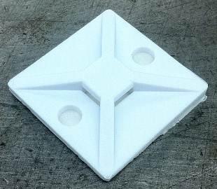
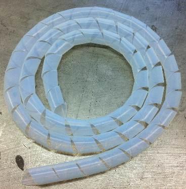
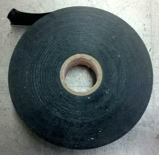
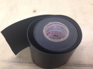
4 Parts List Quantity Item Supplier Part Number Cost 1 DIN Rail With PEM Studs 68D7101G01 $12.60 Each 22 Insulated Eye Terminals #6 Screw, AWG K23 $7.04 per 50 6 Two-Pole Jumpers K79 $4.55 per 25 4 #8-32 Nylock Nuts A009 $2.30 per Spacers for #8 Bolt A133 $1.05 Each 1 Sixteen Terminal Block K75 $8.12 Each 5 Zip Tie K19 $3.78 per Zip Tie Holder K62 $11.32 per 50 3 Feet Translucent Wire Sleeving K741 $8.97 per foot 8 Inches 3M Fire & Arc Protect Tape A4 $28.28 per 20 feet 1 3M Electrical Tape A21 $2.03 per 20 feet Monti Contact Info: Nick LaVigne nickl@monti-inc.com Airport Industrial Road, Greenwood, SC Eye Terminals DIN-Rail with PEM Studs Two-Pole Jumper 4 of 41


5 #8-32 Nylock Nuts #8 Spacers Zip Tie Holder Sixteen Terminal Block Zip Tie Translucent Wire Sleeving Electrical Tape Arc Protect Tape 5 of 41

6 PROCEDURE Step 1: Locate the secondary control power wiring terminal box on the breaker. Figure 1: Breaker side secondary Terminal Box. 6 of 41


7 Step 2: Insert flat head screwdriver into the two clips to release the front cover. Figure 2: Schematic of the how to remove the front cover on the secondary. 7 of 41
.")
8 Step 3: Using the male pin remover, take out each pin. This can be accomplished by pressing the male pin remover into a pin slot and pushing hard to unseat the pin. Once the pin has been unseated, push from the opposite side of the secondary connector to pull the pin out of its slot. Repeat for ALL pins (more figures on next page). Figure 3a: Line up the male pin remover with a pin. 8 of 41


9 Figure 3b: Press the male pin remover in hard to unseat the pin. Figure 3c: Once unseated by the male pin remover, push on the pin from the opposite side to get the pin out of the slot. Repeat for all pins. 9 of 41

10 Step 4: Once all pins have been taken out of their slots, remove the secondary connector and rubber tubing. Discard if desired. Rubber Tubing Secondary Connector Figure 4: Remove the gray rubber tubing and secondary connector, they will not be used. 10 of 41
 needed wires.")
11 Step 5: Separate the (14) wires needed for the secondary terminal block from the rest of the wires and set aside. See appendix A for a listing of the necessary wires. Figure 5: Separating the (14) needed wires. 11 of 41

12 Step 6: Pull the unnecessary wires through the hole in the top of the breaker. These wires will be secured inside the breaker in the proceeding steps. 14 Needed Wires Figure 6: Pull out the unnecessary wires. 12 of 41

13 Step 7: Wrap about (22) inches of transparent protective covering around these unnecessary wires. These wires that are not needed will be secured inside of the breaker. Figure 7: Transparent protective wiring cover. 13 of 41

14 Step 8: If too long, cut the transparent protective wiring cover two inches from the end of these unnecessary wires. Figure 8: Removal of excessive wiring cover. 14 of 41

15 Step 9: Cut an 8 inch section of the fire retardant arc protective tape. Figure 9: Cutting an 8 inch section of arc protective tape. 15 of 41

16 Step 10: Wrap the arc protective tape around the exposed portion of the unneeded wires. Then, secure this protective tape with the electrical tape. Figure 10: Wrapping the unneeded wires in electrical tape. 16 of 41

17 Step 11: Wrap the unused wires completely with electrical tape. Figure 11: Unneeded wires completely covered. 17 of 41
 cable tie holders on the inside wall of the breaker (spring side).")
18 Step 12: We will now secure the unused wires inside the breaker. Place (2) cable tie holders on the inside wall of the breaker (spring side). Position them about three inches from each other and a half inch from the front edge. Figure 12: Placement of cable tie holders. 18 of 41

19 Step 13: Insert cable ties through the inslots of the tie holders to secure the unused wires. Figure 13: Securing of the unneeded wires. 19 of 41

20 Step 14: Place another cable tie holder as shown closer to the back of the breaker to hold the end of the unneeded wire bundle in place. Zip tie the bundle to the cable-tie holder. Figure 14: Securing of the wires to avoid interference with spring. 20 of 41
 Zip Ties Figure 15a (left): Used three zip ties to secure the unused wires to the inner wall.")

21 Step 15: The wires should be secured in this manner and any excess cable ties should be clipped. (3) Zip Ties Figure 15a (left): Used three zip ties to secure the unused wires to the inner wall. Figure 15b (right): Wires are secured from both the closing and open spring assemblies. In Process Quality Check: Operate the breaker mechanically and make sure no moving parts interfere with the wiring. 21 of 41

22 Step 16: Wrap transparent wiring cover around the (14) wires used for the terminal blocks. The wiring cover should span roughly eight inches. Figure 16: Wrapping of the transparent wire covering on terminal wires. 22 of 41

23 Step 17: Unfasten the bolt on the top center of the breaker that helps secure the mechanism in place using a 10 mm wrench. Figure 17: Temporary removal of the center bolt. It will be used for mounting the mounting bracket. 23 of 41

24 Step 18: Unfasten this bolt on the underside of the top-right of the breaker ground terminal connection bolt using an 8 mm wrench. Figure 18: Removal of the bolt. 24 of 41

.")
25 Step 19: Fasten the DIN-Rail onto the top of the breaker using the bolts removed in steps 17 and 18. For the bolt on the right, remember to reconnect the grounding wire on the inside (Figure 18). You will not be able to access the breaker s center bolt once the terminal block is mounted on the DIN-Rail. Figure 19: Securing of the din-rail. 25 of 41
")

 PEM studs and")
26 Step 20: Fasten the terminal block to the four PEM studs on the DIN-Rail using the (4) spacers and the (4) Nylon Locking Nuts. Figure 20a: Place terminal block on PEM studs Figure 20b: Place spacers and nylon locking nuts on all (4) PEM studs and tighten down. 26 of 41

27 Step 21: Slide the white wire labels on the wires back until they reach the transparent wire cover. Figure 21: Sliding the white labels back. 27 of 41

28 Step 22: Remove excess wire on each wire by lining up the wire with the center of the terminal designated for that wire. The wires will increase in length as you go down the DIN-Rail from left to right. See appendix A for the proper location of each wire to determine the appropriate length. Figure 22: Snipping of the wires. 28 of 41

.")

29 Step 23: Strip all 14 wire ends using the wire stripper. Wires are 14 Gauge and should be stripped approximately 0.25 (7mm). Figure 23a: Stripping each wire. Figure 23b: All needed wires have been stripped. 29 of 41


30 Step 24: For each wire, place the ring to be crimped on the end of each wire, allowing a small amount of the wire to be exposed. Then crimp the ring terminal to the wire. Exposed Wire Figure 24a: Uncrimped ring terminal on stripped wire. Figure 24b: Crimping the ring terminals on. 30 of 41

31 Step 25: Repeat step 24 for all wires. Figure 25: All wires are the appropriate length and have ring terminals crimped on. 31 of 41
 for wiring locations. Figure 26: Attach each wire to its terminal.")
32 Step 26: Attach the appropriate wire to the appropriate terminal. Repeat for all wires. See attached appendix (A) for wiring locations. Figure 26: Attach each wire to its terminal. There will be two extra terminals that can be used for future needs. 32 of 41
 of the two-pole jumpers and arrange them on the terminal block so terminals 1 through 4 are connected together.")

33 Step 27: Take the first 8 screws out of the non-breaker side of the terminal block. Then, take (3) of the two-pole jumpers and arrange them on the terminal block so terminals 1 through 4 are connected together. Take another (3) jumpers to connect terminals 5 through 8. Screw the jumpers into place using the terminal block screws. Figures 27a & 27b: Terminals 1-4 will be jumped together. Terminals 5-8 will also be jumped together. Ensure 4 & 5 are NOT jumped together. Jump 1-4 Jump 5-8 No Jumper 33 of 41


34 Step 28: Attach a cable tie holder to the top of the breaker and secure the wires with a cable tie. Figure 28a: Place a cable tie holder on top of the breaker. Figure 28b: Use a zip tie to secure the wires. 34 of 41

35 FINAL RESULT 35 of 41
36 QUALITY CHECK Visually inspect the breaker for defects. Make sure all of the electrical connections are correctly secured. Make sure all of the electrical connections are in accordance to the wiring schematic. Make sure all of the bolted connections that were added as a part of this procedure are properly tightened. Electrically test the operation of the breaker to make sure the modifications were correctly done and that the breaker properly operates. Electrically operate the breaker five times for a charge - open - close type operation. Inspect the operation of the large black closing mechanism spring to make sure that it does not hit the modified wiring harness on the left side of the mechanism side sheet. The spring should have 0.5 or more clearance during opening or closing. Make sure the front cover is properly mounted. 36 of 41
 2 C9 Q1.1:9 X11:7 Normally Open Relay 1 (Hi) 3 C13 Q1.1:13 X11:9 Normally Open Relay 2 (Hi) 4 C7 Q1.")
37 Appendix A: Wiring Locations Figure 29: Graphical locations of each wire. Terminal Position Old CODE New CODE Purpose 1 D1 X11:25 M1:1 Motor Power Supply (Hi) 2 C9 Q1.1:9 X11:7 Normally Open Relay 1 (Hi) 3 C13 Q1.1:13 X11:9 Normally Open Relay 2 (Hi) 4 C7 Q1.1:7 X11:23 Normally Closed Relay (Hi) 5 H4 X11:44 Y6:2 UVR Return (Lo) 6 P2 X11:14 U2:2 Close Coil Return (Lo) 7 F22 M1.2:22 X11:35 Motor Return (Lo) 8 C2 Q1.1:2 X11:30 Trip Coil Return (Lo) 9 H3 X11:2 Y6:1 UVR Power Supply (Hi) 10 P1 X11:4 U2:1 Close Coil Power Supply (Hi) 11 P7 X11:31 U2:7 Trip Coil Power Supply (Hi) 12 C10 Q1.1:10 X11:17 Normally Open Relay 1 (Lo) 13 C14 Q1.1:14 X11:19 Normally Open Relay 2 (Lo) Note: The 14 X11 designation C8 refers to the Q1.1:8 X11:33 secondary connector. For Normally example, Closed X11:25 Relay is the (Lo) 25 th pin on the secondary connector. 37 of 41
.")
38 Appendix B: Wiring Diagram Figure 30: Graphical schematic of terminal assembly and breaker circuits (breaker is in the open position). 38 of 41
39 Appendix C: DIN-Rail with PEM Studs (Inches) 39 of 41
40 Appendix D: W-VACiMB Wiring Diagram 40 of 41

41 Appendix E: New Overall Breaker Dimensions 41 of 41
42 Appendix F: Wire Identification Sheet The labels above can be copied and taped to the top of the breaker for easy identification of each wire and its purpose. 42 of 41
Assembly & Installation Instructions
 TM P R O D U C T S Assembly & Installation Instructions FOR 28 SERIES SNOWPLOW PIVOT ASSEMBLY AND FLOAT LIMITER 99103000 FOR SERIAL NUMBERS 28D100000 TO 28D100770 97100552A 1. THINK SAFETY, ALWAYS WEAR
1956 Ford Passenger Car Control Panel Conversion Kit (473150)
") an ISO 900:2008 Registered Company 956 Ford Passenger Car Control Panel Conversion Kit (47350) 8865 Goll St. San Antonio, TX 78266 Phone: 20-654-77 Fax: 20-654-33 www.vintageair.com 900505 REV B 04/4/5,
an ISO 900:2008 Registered Company 956 Ford Passenger Car Control Panel Conversion Kit (47350) 8865 Goll St. San Antonio, TX 78266 Phone: 20-654-77 Fax: 20-654-33 www.vintageair.com 900505 REV B 04/4/5,
LEXUS GX TOWING HITCH Preparation
 LEXUS GX460 2014 - TOWING HITCH Preparation Part Number: PT228-60140 Kit Contents Item # Quantity Reqd. Description 1 1 Hitch Assembly 2 1 Wiring Harness Bracket 3 1 Hardware Bag 4 1 Hitch Cover 5 2 Center
INSTALLATION MANUAL
 INSTALLATION MANUAL 2563000 Parts List 1 Carrier weldment 2 Support arm assembly 1 Third brake light assembly 1 Light extension bracket 1 Spare tire adjustment plate 1 Spare tire mount plate 1 Female spade
Power Break II Circuit Breaker Accessories Motor Operator Mechanism
 g GEH 6281E Power Break II Circuit Breaker Accessories Motor Operator Mechanism Introduction The Motor Operator Mechanism, shown in Figure 1, can be installed in 800 4000 A frame Power Break II circuit
USB Charge Port Installation Instructions
 USB Charge Port Installation Instructions Lifetime Technical Support support@logolites.com 770-476-7322 www.logolites.com Manual 100-0014C Thank you for purchasing a Logo Lites USB Charge Port! USB Charge
LEXUS CT 200h ILLUMINATED DOOR SILLS Preparation
 Preparation Part Number: PT922-89100 Kit Contents Item # Quantity Req'd. Description 1 1 Door Sill, Front Right Hand 2 1 Door Sill, Front Left Hand 3 1 Door Sill, Rear Right Hand 4 1 Door Sill, Rear Left
INSTALLATION MANUAL HYDRAULIC HOSE REEL
 INSTALLATION MANUAL HYDRAULIC HOSE REEL 1 TABLE OF CONTENTS SECTION PAGE SECTION PAGE 1 HOW TO ORDER PARTS 3 MAINTENANCE SCHEDULE... 11 1.1 HOW TO ORDER PARTS... 2 1.2 MODEL IDENTIFICATION... 3 2 INSTALLATION
Installation Instructions for Key Switch SNOWRATOR
 2017 Installation Instructions for Key Switch SNOWRATOR We appreciate your purchase of L.T. Rich s Product. Please read carefully before Operating or detaching. AES L.T.RICH 6/15/2017 SHIPPING CONTENTS...
SCION FR-S FOG LIGHTS
 Part #: PT413-18130 Conflicts: Lowering Springs PTR07-18130-LL (California only) Kit Contents: For Anniversary Edition, Monogram & RS 2.0 vehicles, additional parts need to be ordered (PT413-18130-LL)
CM52 Network Protector with Arc Flash Reduction Module
 Contents Description Page 1: General.............................. 2 2: Maintenance Mode Settings.............. 2 3: Arming Maintenance Mode.............. 2 4: Remote Indicator....................... 2
Installation Instructions for Lingenfelter GM 2500 Suburban & Yukon XL Auxiliary Fan System (with AC clutch controlled fan output)
") Installation Instructions for Lingenfelter 2007-2013 GM 2500 Suburban & Yukon XL Auxiliary Fan System (with AC clutch controlled fan output) PN L300080607 Revision - 1.1 Lingenfelter Performance Engineering
Installation Instructions for Lingenfelter 2007-2013 GM 2500 Suburban & Yukon XL Auxiliary Fan System (with AC clutch controlled fan output) PN L300080607 Revision - 1.1 Lingenfelter Performance Engineering
SHELBY GT500
 2007-2009 SHELBY GT500 Removal of Factory Unit WARNING: 1. Radiator fluid must be handled properly. Please observe local ordinances with regards to handling and disposal. 2. Allow vehicle and components
Adjustable Light Kits E-Z-Go TXT All Models Installation Instructions
 Adjustable Light Kits E-Z-Go TXT All Models 1996-2013 Installation Instructions Caution: Please read through the instructions carefully. Before starting this project, remove the system s positive and negative
3 in 1 TRAIL CHARGER with LOCKOUT
 Owner s Manual P/N: 283821 500 3 in 1 TRAIL CHARGER with LOCKOUT 283821 01 Version 2.04 07/05/2011 Owners Manual Operation Installation Wiring Diagram Troubleshooting Parts Breakdown 1 GENERAL OPERATION
Chevrolet Camaro/ Pontiac Firebird with Factory Air Control Panel Conversion Kit (475166)
") an ISO 900:205 Registered Company 967-68 Chevrolet Camaro/ Pontiac Firebird with Factory Air Conversion Kit (47566) 8865 Goll St. San Antonio, TX 78266 Phone: 800-862-6658 Sales: sales@vintageair.com Tech
an ISO 900:205 Registered Company 967-68 Chevrolet Camaro/ Pontiac Firebird with Factory Air Conversion Kit (47566) 8865 Goll St. San Antonio, TX 78266 Phone: 800-862-6658 Sales: sales@vintageair.com Tech
Installation Instructions
 Installation Instructions Jeep JK 2-Door (2011 Present) Mounting Bracket and Air Line System Kit for ARB On-Board Twin Air Compressor (CKMTA12) Made in the USA Kit Contents: 1 Flat Bracket 1 Formed Bracket
Chevrolet Full-Size 3-Lever Control Panel Conversion Kit (473059)
") an ISO 900:2008 Registered Company 955-56 Chevrolet Full-Size -Lever Control Panel Conversion Kit (47059) 8865 Goll St. San Antonio, TX 78266 Phone: 800-862-6658 Sales: sales@vintageair.com Tech Support:
an ISO 900:2008 Registered Company 955-56 Chevrolet Full-Size -Lever Control Panel Conversion Kit (47059) 8865 Goll St. San Antonio, TX 78266 Phone: 800-862-6658 Sales: sales@vintageair.com Tech Support:
Installation Instructions
 Installation Instructions Jeep JK Unlimited (2007 Present) Mounting Bracket and Air Line System Kit for ARB On-Board Twin Air Compressor (CKMTA12) Made in the USA Kit Contents: 1 Bracket for ARB Compressor
TOYOTA RAV FOG LIGHT KIT Preparation
 Preparation Part Number: PT413-42163 Kit Contents Item # Quantity Reqd. Description 1 7 7 Wire Tie 2 4 #10-16 Cross Pan-Washer Head Screws 3 1 Switch 4 1 Relay 5 1 LH Fog Light Bezel 6 1 RH Fog Light Bezel
INSTALLATION MANUAL. Thunderstone Manufacturing LLC 3400 West O Street Lincoln, NE (Fax)
") INSTALLATION MANUAL August 7 th 2018 43 /48 /50 2011 and Older Timpte STD/Split 36 Style Hopper Trailers with Roller Bearing Doors Kit #101533 for 96w & Kit #101534 for 102w Thunderstone Manufacturing
INSTALLATION MANUAL August 7 th 2018 43 /48 /50 2011 and Older Timpte STD/Split 36 Style Hopper Trailers with Roller Bearing Doors Kit #101533 for 96w & Kit #101534 for 102w Thunderstone Manufacturing
2015 Mustang Lightbar (All Models) CDC#
 CDC#") 2015 Mustang Lightbar (All Models) CDC# 1511-7000-01 Components: 1 CDC Lightbar Note: READ instructions before starting installation!!! CDC Part# Driver side bracket 0511-6001-05 Passenger side bracket
2015 Mustang Lightbar (All Models) CDC# 1511-7000-01 Components: 1 CDC Lightbar Note: READ instructions before starting installation!!! CDC Part# Driver side bracket 0511-6001-05 Passenger side bracket
Cut zip ties and remove 2 plastic wiring harness brackets.
 TROUBLESHOOTING: Please read and understand all installation instructions before proceeding with the installation. Included parts: 1 - New Bosch Cp3 Pump 1 - HSM Pulley 1 - Serpentine Belt 1 - Pump Bracket/
Service Procedure COL-211
 TRW Automotive Commercial Steering Systems Service Procedure COL-211 J19-6032/6033 Steering Column Horn Contact Remove and Replace Procedure Use when installing service kit 453107X2 This ZF Commercial
CHEVROLET FULL-SIZE
 an ISO 900: 2008 Registered Company 955-56 CHEVROLET FULL-SIZE 4-LEVER CONTROL PANEL CONVERSION KIT 473056 903054 REV D 9/7/4, INST 955-56 CHEVY CNTRL PNL PG OF 2 Table of Contents PAGES. COVER 2. TABLE
Current parts on a ROTAX 125 MAX DD2 evo
 Current parts on a ROTAX 125 MAX DD2 evo No. Part. No. Name Qty. USAGE for rework? 1 660 575 Pressure Line 220 mm 1 YES 2 666 816 Electronic Box DD2 1 YES 3 660 825 Ignition Coil 1 YES 4 664 630 Solenoid
HUMMER H A. 3-5 Hours INSTALLATION GUIDE INSTALLATION TIME SKILL LEVEL. 4= Experienced TOOLS REQUIRED APPLICATION MODEL YR PART #
 INSTALLATION GUIDE APPLICATION MODEL YR PART # HUMMER H2 2003-2009 75107-01A INSTALLATION TIME 3-5 Hours Professional installation recommended SKILL LEVEL 1 2 3 = Experienced TOOLS REQUIRED Safety goggles
INSTALLATION INSTRUCTIONS
 INSTALLATION INSTRUCTIONS Part# 22-2719 Complete Mounting System for Dual Viair Compressors For the most up-to-date instructions please visit www.updownair.com www.updownair.com 833-226-4863 I M P O R
LGT-312L E-Z-Go TXT Light Bar Bumper Kit Installation Instructions
 LGT-312L E-Z-Go TXT 2014+ Light Bar Bumper Kit Installation Instructions Caution: Please read through the instructions carefully. Before starting this project, remove the system s positive and negative
Installation Instructions Z-Gate Shifter
 Installation Instructions Z-Gate Shifter Part Number 80681 1998, 2001 by B&M Racing and Performance Products The B&M Z-Gate shifter can be used in vehicles equipped with most popular three speed automatic
2016 HONDA 1000 Pioneer PN 3102 Turn signal / horn kit rev nc
 2016 Honda 1000 Pioneer STOP - THIS KIT IS DESIGNED SPECIFICALLY FOR 2016 HONDA 1000 PIONEER IF YOUR MACHINE IS NOT THIS MODEL DO NOT PROCEED. THIS KIT DOES NOT WORK ON THE PIONEER 500 nor 700 S. Contact
Ford Mustang with Factory Air Control Panel Conversion Kit (475170)
") an ISO 900:205 Registered Company 969-70 Ford Mustang with Factory Air Control Panel Conversion Kit (47570) 8865 Goll St. San Antonio, TX 78266 Phone: 800-862-6658 Sales: sales@vintageair.com Tech Support:
an ISO 900:205 Registered Company 969-70 Ford Mustang with Factory Air Control Panel Conversion Kit (47570) 8865 Goll St. San Antonio, TX 78266 Phone: 800-862-6658 Sales: sales@vintageair.com Tech Support:
INSTALLATION INSTRUCTIONS
 INSTALLATION INSTRUCTIONS PARTS LIST Accessory Application Publications No. TRX420 (All) MII 13032 WINCH KIT P/N 08L94-HP5-100 Accessory Weight 35 lbs (16 kg) Honda Dealer: Please give a copy of these
SPACESAVER EC-300 A ELECTRICS
 INSTALLATION INSTRUCTIONS SPACESAVER EC-300 A ELECTRICS SECTION I TOP MOUNTED ELECTRICS SECTION II FACE PANEL MOUNTED ELECTRICS SECTION III ZFS INSTALLATION INSTRUCTIONS This symbol indicates a connection
2015 Current F150/Raptor Venom Side Steps Installation Instructions
 2015 Current F150/Raptor Venom Side Steps Installation Instructions PREPARATION STEPS 1. Disconnect the negative terminal on the battery. Park the vehicle on level ground and set the emergency brake. 2.
Chevrolet Camaro without Factory Air Control Panel Conversion Kit
 an ISO 900:205 Registered Company 967-68 Chevrolet Camaro without Factory Air Control Panel Conversion Kit 47568 8865 Goll St. San Antonio, TX 78266 Phone: 800-862-6658 Sales: sales@vintageair.com Tech
INSTALLATION INSTRUCTIONS
 28 INSTALLATION INSTRUCTIONS SECTION - AIR SPRING SECTION 2 - AIR ACCESSORY 2-5 ! IMPORTANT PLEASE DON T HURT YOURSELF, YOUR KIT OR YOUR VEHICLE. TAKE A MINUTE TO READ THIS IMPORTANT INFORMATION. This
Signal Mirror Installation Instructions Standard West Coast Mirror
 Signal Mirror Installation Instructions Standard West Coast Mirror THE safety accessory of the 21 st Century. P/N 210-0058-0 Rev A1 (6-29-04), GG 2002 Muth Mirror Systems, LLC. Note: Professional Installation
Safe-T-element Installation Instructions
 Safe-T-element Installation Instructions For: PTI STEZA (2x2 Burner Configuration) & PTI STEZB (3x1 Burner Configuration) Revision K (May. 3 2012) TABLE OF CONTENTS 1. PREPARATION... 3 1.1 General Safety
V2 INTAKE SYSTEM. Installation Instructions for: Part Number Acura RSX
 V2 INTAKE SYSTEM Installation Instructions for: Part Number 24-6105 2002-2003 Acura RSX ADVANCED ENGINE MANAGEMENT INC. 2205 126 TH Street, Unit A Hawthorne, CA. 90250 Phone: (310) 484-2322 Fax: (310)
P3066 INSTALLATION MANUAL
 P3066 INSTALLATION MANUAL Parts List 1 Grille guard 1 Driver / left frame bracket Level of Difficulty Moderate Scan for helpful install tips 1 Passenger / right frame bracket 1 Driver / left top bracket
INSTALLATION INSTRUCTIONS
 Equipped with AEM Dryflow Filter No Oil Required! INSTALLATION INSTRUCTIONS PART NUMBER: 24-6105 2002-2006 ACURA RSX - Excludes Type S L4-2.0L C.A.R.B. E.O. # D-670 * NOTE: Legal in California only for
INSTALLATION & OWNER S MANUAL
 Rev. A, p. 1 of 13 INSTALLATION & OWNER S MANUAL Polaris Ranger (2009-) Straight UTV Steel Plow with Vehicle Mount Kit 6 Wide Snow Plow (p/n: 1POLSP) (fits the 500 H.O., 700 & 800 HD & XP) The contents
TOYOTA RAV TRAILER WIRE HARNESS Section I Installation Preparation
 Section I Installation Preparation Part Number: 08921-42900 Kit Contents Item # Quantity Reqd. Description 1 1 Converter 2 1 Wire harness 3 1 Sub wire harness No.1 4 2 Plastic Tie (300mm) 5 21 Plastic
INSTALLATION INSTRUCTIONS FUEL SURGE TANK KIT
 INSTALLATION INSTRUCTIONS FUEL SURGE TANK KIT BMW E46 3-Series, Excl Convertible Document: 19-0056 Support: info@radiumauto.com Relieve fuel pressure in vehicle before beginingthe installation. Disconnect
JEEVES. JEEVES Installation Manual. Installation Manual The Easiest Do-It-Yourself Dumbwaiter on the Market
 1 888-323-8755 www.nwlifts.com JEEVES Installation Manual The Easiest Do-It-Yourself Dumbwaiter on the Market This manual will cover the installation procedure step-by-step. The installation of this dumbwaiter
LPE C5 Battery Relocation Kit
 LPE C5 Battery Relocation Kit The LPE C5 Corvette battery relocation kit improves vehicle weight distribution by moving weight to the rear of the vehicle. The improved weight distribution increases traction
Front Fog Lamp Package Installation
 Service Information 2014 Cadillac SRX SRX VIN N Accessory Installation Manual Accessories Electrical Accessories Accessories Document ID: 2242151 Front Fog Lamp Package Installation Table 1: Table 2: Kit
PRODUCT SAFETY NOTICE DEALER/INSTALLER NOTICE
 PRODUCT SAFETY NOTICE Congratulations. This vehicle has been equipped with a Firestone air suspension system. This suspension will enhance the vehicle s handling when loaded, however, the vehicle s performance
Ford Mustang V6 OEM-Style Fog Light Kit Parts List: Quantity: Tool List:
 2015-2017 Ford Mustang V6 OEM-Style Fog Light Kit Parts List: Quantity: Tool List: LED Foglights/ Bezels 2 Flat head & Phillips screwdriver (if you ordered part#3600) Ratchet & Socket set OR Wiring harness
Gauge Wiring Instructions
 Thank you for purchasing the Track Dog Racing Gauges. These instructions are for wiring the Westach brand gauges with the TDR gauge panel for all model years of the Miata. Refer to the installation instructions
SAFETY THIS PRODUCT IS FOR OFFROAD USE ONLY. ALL LIABILITY FOR INSTALLATION AND USE RESTS WITH THE OWNER.
 SAFETY Your safety and the safety of others is very important. In order to help you make informed decisions about safety, we have provided installation instructions and other information. These instructions
LEXUS RC 350/RC-F ILLUMINATED DOOR SILLS Preparation
 Preparation Part Number: PT944-24150 Kit Contents Item # Quantity Reqd. Description 1 2 Inner LED Scuff 2 2 Outer Scuff 3 1 Hardware Bag Hardware Bag Contents Item # Quantity Reqd. Description 1 15 20
SAFETY THIS PRODUCT IS FOR OFFROAD USE ONLY. ALL LIABILITY FOR INSTALLATION AND USE RESTS WITH THE OWNER.
 SAFETY Your safety and the safety of others is very important. In order to help you make informed decisions about safety, we have provided installation instructions and other information. These instructions
TRUCK STORAGE SOLUTIONS FOR THE WAY YOU WORK INSTALLATION MANUAL SADDLE BOX STARTER KIT. Model: QDSKSA01. Part No.
 TRUCK STORAGE SOLUTIONS FOR THE WAY YOU WORK INSTALLATION MANUAL SADDLE BOX STARTER KIT Model: QDSKSA01 Part No. 24-0326 Rev. A ECN 5430 ATTENTION: PLEASE READ AND UNDERSTAND ALL INSTRUCTIONS AND WARNINGS
LI-ION BATTERY UPFIT KIT
 LI-ION BATTERY UPFIT KIT P/N 2881852 APPLICATION E2, E4, E6, and el XD BEFORE YOU BEGIN Read these instructions and check to be sure all parts and tools are accounted for. Please retain these installation
Thank you for your purchase! Please read all instructions carefully prior to beginning installation of your Rock Hard 4x4 product.
 ROCK HARD 4X4 JEEP WRANGLER JK 2/4-DOOR 2007-2017 FRONT BUMPER (ALL) PART #: RH-5001-B / 5002 / 5003 / 5004 / 5005 / 5006 / 5007 / 5008 / 5009 / 5041 / 5042 / 5045 / 5046 Installation Manual PACKING LIST:
1969 Chevrolet Camaro with Factory Air Control Panel Conversion Kit (474269)
") an ISO 900:2008 Registered Company 969 Chevrolet Camaro with Factory Air Control Panel Conversion Kit (474269) 8865 Goll St. San Antonio, TX 78266 Phone: 20-654-77 Fax: 20-654-33 www.vintageair.com 904269
an ISO 900:2008 Registered Company 969 Chevrolet Camaro with Factory Air Control Panel Conversion Kit (474269) 8865 Goll St. San Antonio, TX 78266 Phone: 20-654-77 Fax: 20-654-33 www.vintageair.com 904269
TOYOTA VENZA 2009 TRAILER WIRE HARNESS Procedure
 Part Number: PT791-0T099 Kit Contents Item # Quantity Reqd. Description 1 1 Trailer Wire Harness Module 2 1 4-Flat Harness 3 1 Battery Power Wire Harness 4 1 Mounting Bracket, 4-Flat 5 2 Screw #10-24 6
Installation Instructions for R-Frame G-Series (RG) 310+ Trip Unit
 310+ Trip Unit") Instruction Leaflet IL01210020E Installation Instructions for R-Frame G-Series (RG) 310+ Trip Unit Contents Description Page 1. Removal of R-Frame Electronic Seltronic (RES) Trip Unit and Obsolete Components...
Instruction Leaflet IL01210020E Installation Instructions for R-Frame G-Series (RG) 310+ Trip Unit Contents Description Page 1. Removal of R-Frame Electronic Seltronic (RES) Trip Unit and Obsolete Components...
Digitrip Retrofit System for ITE K-3000, K-3000 S, K-4000 and K-4000 S Breakers
 Supersedes IL 33-858-4 Dated 05/02 Digitrip Retrofit System for ITE K-3000, K-3000 S, K-4000 and K-4000 S Breakers Digitrip Retrofit System for ITE K-3000, Digitrip Retrofit System for ITE K-3000, K-3000
Desktop 5.5 Z Axis Retrofit
 Page 1 Kit parts Desktop 5.5 Z Axis Retrofit Carriage plate with stop bolt and Z proximity switch installed Zip ties Spare bolts Spindle mounting plate with stop bolt, spring mount, and rail Z proximity
Carousel Unit User Manual Replacing the Check Stand Motor
 Carousel Unit User Manual Replacing the Check Stand Motor 02/01/2017 1 Table of Contents Tools:... 3 Turn Off Power to the Unit:... 4 Remove Power Switch... 5 Remove Electric Eyes:... 6 Remove POS (Point-Of-Sale)
2017 Current Ford SuperDuty Adaptive Cruise Control Relocation Bracket Installation Instructions
 2017 Current Ford SuperDuty Adaptive Cruise Control Relocation Bracket Installation Instructions PREPARATION 1. Disconnect the negative terminal on the battery. Park the vehicle on level ground and set
INSTALLATION INSTRUCTIONS
 Rear Vision System Tailgate Emblem Camera Aftermarket Display 2009-Current Ford F-150 and 2010-Current Super Duty (Kit part number 1008-6509) Kit Contents: Tailgate Emblem Mount with Camera Chassis Harness
Pontiac GTO with Factory Air Control Panel Conversion Kit (473167)
") an ISO 900:008 Registered Company 964-67 Pontiac GTO with Factory Air Control Panel Conversion Kit (4767) DE-ICE HEAT OFF VENT OUT INSIDE 8865 Goll St. San Antonio, TX 7866 Phone: 0-654-77 Fax: 0-654-
an ISO 900:008 Registered Company 964-67 Pontiac GTO with Factory Air Control Panel Conversion Kit (4767) DE-ICE HEAT OFF VENT OUT INSIDE 8865 Goll St. San Antonio, TX 7866 Phone: 0-654-77 Fax: 0-654-
INTEGRATED ENGINE BRAKE ENGINE MUST USE HARMONIC BALANCER - CUMMINS PART #
 INTEGRATED ENGINE BRAKE P55005 P67 LoadLeash Kit: Commercial Trucks with a Cummins 6.7L / Paccar PX-6 ENGINE MUST USE HARMONIC BALANCER - CUMMINS PART # 4938209 Thank you for purchasing a Pacbrake P67
TESLA MODEL S REAR UNDER SPOILER & DIFFUSER SYSTEM
 TESLA MODEL S Thank you for purchasing your Unplugged Performance Rear Under Spoiler & Diffuser System for the Tesla Model S! Please read this manual carefully prior to installation. REAR UNDER SPOILER
Fitting Instructions
 Reverse Park Assist Suitable for: Nissan Navara Kit Part No: 5466XX NP00 Tow-Pro Wiring Kit Fitting Instructions Accessory Kit Estimated Fitting Time: 0 Minutes FI98 Page 0 of 5 General Notes Read through
Spectra Series Power Panelboards. General. Installation. Bolt-On Circuit Breaker Kits. DEH059 Installation Instructions
 g DEH059 Installation Instructions R02 Spectra Series Power Panelboards Bolt-On Circuit Breaker Kits General WARNING: Danger of electrical shock or injury. Turn OFF power ahead of the panelboard or switchboard
Remove black panel shown. Save 6 retaining pins for re-install later. Pry up on center part of pin first. Then pry out entire retaining pin.
 2005-2009 Ford Mustang V6 Fog Light Wiring Kit Parts List: Quantity: Tools Required: Wiring harness 1 Flat head screwdriver Supplemental wire leads 2 Ratchet & Socket set OR Wire tap red 2 Adjustable Wrench
OIL COOLER KIT CHEVY CAMARO 2.0T PARTS LIST AND INSTALLATION GUIDE INSTALL DIFFICULTY DISCLAIMER CAUTION TOOLS NEEDED NOTE INSTALL PROCEDURE
 PARTS LIST AND PARTS INCLUDED 3PC APPLICATION-SPECIFIC MOUNTING BRACKETS 1PC HORN RELOCATION MOUNTING BRACKET 1PC 25-ROW OIL COOLER (SLEEK SILVER OR STEALTH BLACK) 1PC 4'4" STAINLESS STEEL BRAIDED HOSE
Pontiac GTO without Factory Air Control Panel Conversion Kit (473166)
") an ISO 900: 205 Registered Company 964-67 Pontiac GTO without Factory Air Control Panel Conversion Kit (47366) HI AIR MED LO TEMP NORMAL DE-ICE WARMER 8865 Goll St. San Antonio, TX 78266 Phone: 800-862-6658
an ISO 900: 205 Registered Company 964-67 Pontiac GTO without Factory Air Control Panel Conversion Kit (47366) HI AIR MED LO TEMP NORMAL DE-ICE WARMER 8865 Goll St. San Antonio, TX 78266 Phone: 800-862-6658
Your Legal Fuel Tank Source.
 February 23, 2015 IS# 808 Page 1 of 13 THANK YOU FOR PURCHASING A TRANSFER FLOW 40 GALLON TOOLBOX REFUELING SYSTEM. PLEASE READ THE FOLLOWING PROCEDURES CAREFULLY BEFORE STARTING THE INSTALLATION. CAUTION:
ROAD TECH ZUMO GLOBAL POSITIONING SYSTEM (GPS) HANDLE- BAR MOUNT KIT
 HANDLE- BAR MOUNT KIT") -J046 REV. 008-08- ROAD TECH ZUMO GLOBAL POSITIONING SYSTEM (GPS) HANDLE- BAR MOUNT KIT GENERAL Kit Number 965-08 Models This kit is required when using a Road Tech Zumo GPS unit on specific model motorcycles.
-J046 REV. 008-08- ROAD TECH ZUMO GLOBAL POSITIONING SYSTEM (GPS) HANDLE- BAR MOUNT KIT GENERAL Kit Number 965-08 Models This kit is required when using a Road Tech Zumo GPS unit on specific model motorcycles.
Technical Support (707)
") Installation Instructions CONSOLE MEGASHIFTER Fits: 1982-1992 Camaro & Firebird w/automatic Transmission *except 1988-1992 Firebird Formula Model Catalog # 80692 WORK SAFELY! For maximum safety, perform
Installation Instructions CONSOLE MEGASHIFTER Fits: 1982-1992 Camaro & Firebird w/automatic Transmission *except 1988-1992 Firebird Formula Model Catalog # 80692 WORK SAFELY! For maximum safety, perform
Prusa i3 Printer Assembly Guide
 Prusa i3 Printer Assembly Guide Special thanks to Carlos Sanchez and Miguel Sanchez for the graphics. All graphics captured from their great animation: http://www.carlos-sanchez.com/ Prusa3/ For copyright
Technical Support Line: (952) Fax Line: (952) Hanover Ave. Lakeville, MN
 Fax Line: (952) Hanover Ave. Lakeville, MN") Technical Support Line: (952) 985-5675 Fax Line: (952) 985-5679 21730 Hanover Ave. Lakeville, MN 55044 www.qa1.net INSTALLATION INSTRUCTIONS QA1 P/N CC104MU Camber Caster Plates 1994-2004 Mustang 5.0/4.6
Technical Support Line: (952) 985-5675 Fax Line: (952) 985-5679 21730 Hanover Ave. Lakeville, MN 55044 www.qa1.net INSTALLATION INSTRUCTIONS QA1 P/N CC104MU Camber Caster Plates 1994-2004 Mustang 5.0/4.6
System Date of Issue Bulletin Number Bulletin Type. Title: Elimination of AC Connectors J29a and J29b
 System Date of Issue Bulletin Number Bulletin Type Odyne System G2V2 2/4/15 Rev. 10/6/15 00020 Field Service Action Technical Service Bulletin Technical Service Advisory Title: Elimination of AC Connectors
Southwest Windpower Instruction Sheet AIR-X Circuit Replacement Kit
 Southwest Windpower Instruction Sheet AIR-X Circuit Replacement Kit Tools Required 5 / 32 Hex key 5 / 16 Hex key 7 / 64 Hex key Standard screwdriver Pair of external snap ring pliers Rubber mallet Hammer
Wiring Harness Update Kit Assembly Instructions Treker 4200/4400 NT & ST Series Manual No M
 Wiring Harness Update Kit Assembly Instructions Treker 4200/4400 NT & ST Series Manual No. 700-364M Before You Start! When you see this symbol, the subsequent instructions and warnings are serious - follow
INSTALLATION INSTRUCTIONS
 AUTOMOTIVE PRODUCTS, INC. INSTALLATION INSTRUCTIONS ULTIMATE BULL BAR APPLICATION: 2017 Ford F-250/350 PART NUMBER: 32-3900, 32-3905, 32-3900L, 32-3905L ITEM QUANTITY DESCRIPTION TOOLS NEEDED 1 1 ULTIMATE
TOYOTA COROLLA ILLUMINATED DOOR SILLS Preparation
 Preparation Part Number: PT942-02140 Kit Contents Item # Quantity Reqd. Description 1 1 Illuminated Scuff plate, Front Right Hand 2 1 Illuminated Scuff plate, Front Left Hand 3 1 Door Scuff plate, Rear
Wiring the 2015 FRC Control System
 Wiring the 2015 FRC Control System This document details the wiring of a basic electronics board for bench-top testing. The images shown in this section reflect the setup for a Robot Control System using
Not Included. Rear Half Harness
 Basic Light Kit 60102 Caution! Wear appropriate eye protection! Disconnect the battery or batteries. Place run/tow switch in tow position before disconnecting the batteries on models using that feature.
Backside License Plate Mount for Jeep JK Wrangler
 REQUIRED TOOLS 10mm SOCKET 13mm SOCKET 4mm HEX KEY WIRE CRIMPS WIRE STRIPPERS ELECTICAL TAPE SCREW DRIVER KIT CONTAINS BACKSIDE MOUNT LICENSE PLATE BRACKET WITH LEDS PLASTIC PASS-THROUGH GROMMET STAINLESS
SUT-450-I ASSEMBLY REQUIREMENTS
 SUT-450-I Torque wrench, carpenters square, wire cutters, Phillips screwdriver, 7/16, 9/16, and 3/4 combination wrenches, ratchet, 9/16,3/4,13/16, and 7/8 sockets. ASSEMBLY REQUIREMENTS *Torque all T-bolt
Company Switch Installation Instructions and User Manual
 Lex Products Corporation 15 Progress Drive Shelton, CT 06484 203.363.3738 203.363.3742 Fax Lex West 11847 Sheldon Street Sun Valley, CA 91352 818.768.4474 818.768.4040 Fax www.lexproducts.com info@lexproducts.com
TOYOTA COROLLA ILLUMINATED DOOR SILLS Preparation
 Preparation Part Number: PT942-02140 Kit Contents Item # Quantity Reqd. Description 1 1 Illuminated Scuff plate, Front Right Hand 2 1 Illuminated Scuff plate, Front Left Hand 3 1 Door Scuff plate, Rear
PRODUCT SAFETY NOTICE
 PRODUCT SAFETY NOTICE Congratulations. This vehicle has been equipped with a Firestone air suspension system. This suspension will enhance the vehicle s handling when loaded, however, the vehicle s performance
The H-MAC Heavy Metal Articulating Chassis Construction Guide
 The H-MAC Heavy Metal Articulating Chassis Construction Guide The Heavy Metal Chassis is constructed with two identical drive modules built using 10 mechanical sub-assemblies. The drive modules are integrated
***THE OWNER'S MANUAL MUST BE GIVEN TO THE END USE CUSTOMER AFTER COMPLETING THE INSTALLATION.***
 INSTALLATION INSTRUCTIONS FOR THE MOTOR TRIKE HARLEY MECHANICAL REVERSE 1999-2006 FIVE SPEED FLH LAST UPDATED: OCTOBER 2011 AS THE INSTALLER OF THIS MECHANICAL REVERSE, YOU MUST BECOME FAMILIAR WITH PROPER
Installation Instructions PowerBoard Automatic Retracting Running Board
 Installation Instructions PowerBoard Automatic Retracting Running Board Vehicle Application Dodge Ram 1500 Crew Cab 2009 - Current : 75138-15 Dodge Ram 2500/3500 & HD Crew Cab 2010 - Current : 75138-15
Installation Instructions Right Hand Drive Megashifter
 Installation Instructions Right Hand Drive Megashifter Part Number 80685 1995, 2001, 2006, 2010 by B&M Racing & Performance Products The B&M Right Hand Drive Megashifter is designed specifically for vehicles
Installation Instructions for Foam Marker INTERMEDIATE also applies: JR, JR36
 2017 Installation Instructions for Foam Marker INTERMEDIATE also applies: JR, JR36 We appreciate your purchase of L.T. Rich s Product. Please Verify Contents before beginning installation. JLD;AES L.T.RICH
SCION xa 2004 FOG LIGHT Section I Installation Preparation. Part Number: General Applicability
 Section I Installation Preparation Part Number: 81025 52080 Section I Installation Preparation Kit Contents Item # Quantity Reqd. Description 1 1 Assembly, RH 2 1 Assembly, LH 3 1 Switch, 4 1 Relay, 5
Included parts: 1 - New Bosch CP3 Pump 1 - HSM Pulley 1 - Serpentine Belt 1 - Pump Bracket/ Hardware STEP 1
 TROUBLESHOOTING: Please read and understand all installation instructions before proceeding with the installation. If you have questions during the installation of this product, please contact H&S Motorsports
TOYOTA TACOMA TVIP V5
 Preparation Part Number: PT398-35090 Kit Contents Item # Quantity Reqd. Description 1 1 Wire Harness 2 1 Security ECU 3 1 GBS ECU 4 1 Status Monitor/Microphone 5 2 Warning Labels (English) 6 2 Warning
TOYOTA HIGHLANDER RUNNING BOARD HIGHLANDER HV Preparation
 Preparation Part Number: PT738-48080 Kit Contents Item # Quantity Reqd. Description 1 1 Driver Side Running Board 2 1 Passenger Side Running Board 3 4 /Middle Mount Bracket 4 2 Rear Mount Bracket 5 2 Rear
750 Paso Wiring Upgrade
 750 Paso Wiring Upgrade Supplies required: 2 Bosch 30A/12V Relays # #0 332 209 150 (with mounting tab) 1 30 Amp fuse holder 1 10 Amp fuse holder 12 inches of brown 12 gauge wire 60 inches of red 14 gauge