DEFENDERTM ANTI-RAM BOLLARDS PRODUCT DETAIL SPECIFICATION AMERISTARSECURITY.COM
|
|
|
- Ferdinand Hopkins
- 5 years ago
- Views:
Transcription


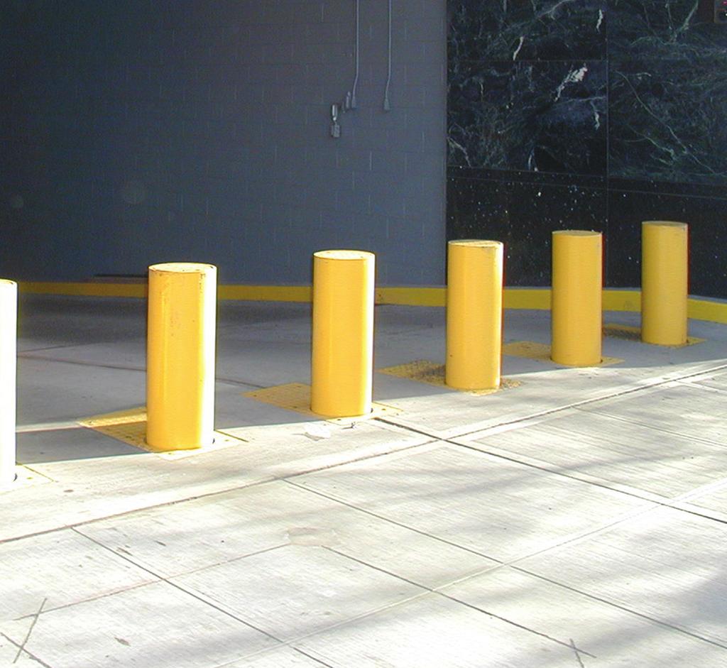
1 DEFENDERTM ANTI-RAM BOLLARDS K4 PRODUCT DETAIL SPECIFICATION AMERISTARSECURITY.COM
2 Section 1 Accreditation 1.01 Hydraulic bollard system Designation High Security Fixed Bollard System 1.02 ST-STD-02.01, April Test Date December 8, Tested by ENSCO Inc., 5400 Port Royal Road, Springfield VA Test Location Georgetown, Delaware Certification Rating DOS K4/L Test Vehicle Make/Type 1968 Ford F GVW 14,885 Lbs Speed achieved mph Penetration Engine running after test NO Vehicle drivable after impact NO Follow on vehicle could pass barrier NO 1.04 Experience The Manufacturer shall have at least 100 similar systems installed and in operation. Section 2 General 2.01 Responsibilities The manufacturer shall be responsible for furnishing each Defender vehicle barrier system and associated equipment as specified The installer shall be responsible for furnishing installation materials, and providing installation, and field testing of each anti-ramming Defender vehicle barrier system including the associated equipment as specified The Owner/Operator (End User) or facility architect will assume responsibility of providing traffic and safety engineering, including all necessary safety features to be used at each bollard site location, including, but not limited to: sidewalks for pedestrian traffic, sufficient roadway lighting, caution signage, traffic (stop) lights, audible warning alerts, visual warning alerts (such as flashing or strobe lights), secondary traffic control devices (such as gate arms), security guard control points, etc The Manufacturer shall supply a Defender vehicle barrier system including multiple bollard type barriers, Hydraulic Power Unit (HPU), operator control panels, and accessories as specified. Page 1 of 17
3 The Manufacturer shall insure that the design and materials of the Defender vehicle barrier system are the same as those used in the crash test of the barrier, and approved by the Department of State (DOS) The vehicle barrier system shall utilize multiple SP Defender electro hydraulic, retractable, round column bollards The installer shall install the Defender vehicle barrier system and shall consist of a minimum of three bollards spaced no greater than 36 inches (914 mm) from centerline to centerline, across a roadway. For roadways exceeding a 10 foot (3 meter) width, additional bollards shall be specified by the Buyer The Installer shall insure the Bollards are equally spaced across the roadway width for full protection coverage Retaining walls, fixed bollards or other devices shall be provided by the installer or facility architects on either side of the bollard set, to prevent vehicles from going around the bollards The Buyer, in conjunction with the Owner/Operator (End User) requirements, will provide the manufacturer with a written sequence of operation Sequence of operation will include but not limited to: the vehicle barrier system sequencing, vehicle loop detector functions, gate arm functions, traffic lights, annunciators and all other equipment directly controlled by the system If the written sequence of operation is not provided by Buyer, then the manufacturer shall supply a default PLC program for basic Defender vehicle barrier system operation only. Additional sequences or functions requested by the Buyer beyond the basic default functions are to be provided by the manufacturer upon written request only and at additional fees to the Buyer. (PLC Only) 2.02 Quality Assurance The manufacturer shall be a company specializing in the supply of vehicle barrier systems with a minimum of 10 years experience The manufacturer shall provide a complete Defender vehicle barrier system that has been fabricated, assembled and tested for proper operation prior to shipment The manufacturer shall have performed an actual crash test on the type of vehicle barrier system being provided Submittals The manufacturer shall submit to the Buyer drawings on the Defender vehicle barrier system Detail drawings shall show the top assembly layout and overall dimensions of each major element of the barrier system equipment, including the bollards, HPU and operator control panels Detail drawings shall show the foundation and anchoring requirements of the Defender vehicle barrier system equipment Detail drawings shall show the layout of a typical Defender vehicle barrier system A detail hydraulic schematic drawing shall be provided. Page 2 of 17
4 A drawing shall be provided showing the size and number of hoses required to run between the bollards and HPU. (Hose length to be determined and provided by installer) A detailed electrical schematic including associated wiring shall be provided showing all electrically connected components, including the interface points for connection to equipment The schematic drawings shall represent the entire Defender vehicle barrier system, with all manufacturer supplied equipment connected and integrated together as a system Detail interconnect drawings shall show the minimum conduit size and number of wires required to run between each of the barrier system equipment The manufacturer shall submit to the Buyer a crash test certification on the Defender vehicle barrier system A copy of the DOS crash rating letter, certifying the manufacturer s barrier shall be provided. As an alternate, the manufacturer may submit the current DOS website address listing the barrier system certified crash rating If an Engineered system is provided a certificate of conformance that the Defender vehicle barrier system delivered conforms to the crash rating, performance and the requirements of this specification The manufacturer shall submit to the buyer a complete list of equipment, materials, including the manufacturer's descriptive data and technical literature, catalog cuts, and installation instructions. As well as Nameplate data which shall be permanently attached to each Defender vehicle barrier and power unit. The data shall be legibly marked on corrosion-resistant metal plates and shall consist of the following: Manufacturer Name Ameristar Security Products Model Number SP Defender Series Serial Number (TBD) Type of barrier Hydraulic, Manual, Fixed, Electric Date of manufacture (TBD) Page 3 of 17
5 The manufacturer shall submit to the buyer a typical bill of material (BOM) and spare parts data for each different item of material and equipment used The Buyer will distribute Defender vehicle barrier system submittal documentation and drawings to the Owner/Operator (End User), as necessary Final Documentation After completion of field tests the Installer shall provide to the Manufacturer up-dated Red-lined drawings, conforming to the as-built equipment provided After completion of field tests the manufacturer shall provide to the Buyer a comprehensive parts and component documentation on the Defender vehicle barrier system, that conforms to the asbuilt equipment provided A Parts List, or Bill of Material, shall be provided on all major parts and components used in the Defender vehicle barrier system A recommended Spare and Consumables Parts List shall be provided. Spare parts shall be those that can be field replaced. Consumables shall include items frequently required for maintenance and service, such as, but not limited to: lights, fuses, lubricants, hydraulic fluid, filter elements, etc. All items shall be provided with a part number, recommended quantity, and a brief description of the item, with current unit prices and source of supply After completion of field tests the manufacturer shall submit to the Buyer an Operation and Maintenance (O&M) Manual A Preface section, with the manufacturer s name, model number and service contact information A Safety Warnings and Cautions section applicable during operation, maintenance, service and/or repair An overview and general description of the Defender vehicle barrier system, including all equipment provided, and a summary of features or characteristics A complete drawing package of the barrier system ordered A theory of operation, for both the hydraulic and electrical circuits An Operating Instructions section, including as a minimum procedures for system start-up, bollard operation, shut down and manual operation A Maintenance Instructions section, including as a minimum routine maintenance requirements, a chart of periodic maintenance activities and intervals, lubrication instructions and component adjustment A Troubleshooting section, with probable cause and an itemized list of equipment checks A Reference Information section, including abbreviations and acronyms, torque values and a list of applicable bollard drawings and documentation After completion of performance verification tests the installer shall submit to both the Buyer and manufacturer a Defender vehicle barrier system PVT Report Upon completion and testing of the installed Defender vehicle barrier system, a Test Report shall be submitted showing both the test data and results of any field tests, including the demonstration and compliance with the specified performance criteria of this specification. Page 4 of 17
6 Each test report shall indicate the final position of component adjustments and set points The Buyer will distribute Defender vehicle barrier system final documentation and drawings to the Owner/Operator (End User), as necessary Delivery, Storage & Handling All equipment shall be prepared and protected by the manufacturer to be shipped by conventional shipping methods The Defender vehicle barrier system equipment shall be protected by suitable methods for the intended shipping and storage environments Packaging, preservation, pallets and crating shall prevent mechanical damage to the equipment during both shipping and handling Forklift provisions (min 10,000 pound capability) shall be provided for the lifting and handling of equipment Shipping containers and crates shall be identified with the type of equipment Shipping documents shall be provided with the contents of each container or crate Equipment received on-site shall be placed in a storage area that is protected from the weather, humidity, excessive temperature variation, dust, dirt and/or other contaminants Equipment shall be stored covered Both equipment and structural materials shall be stored on pallets Equipment shall not be stored directly on the ground, and shall be protected from standing water, and other conditions that might cause rust or corrosion Equipment shall be stored in an area that is not subjected to potential damage by other construction activities Warranty Ameristar Security Products hereby provides the following warranty for any new product purchased from Ameristar Security Products. Ameristar Security Products will provide any components free of charge (freight not included) EX WORKS Tulsa, Oklahoma or EX WORKS vendor if drop shipped, which fail due to poor workmanship or inferior material within the following guidelines after shipment. Ameristar Security Products will warranty the failed part(s). If an Ameristar Security Products technician is required at the customer s facility, the customer will be required to pay technician travel time, work time, and expenses at our normal per diem rates. This warranty shall be effective for the lesser of twelve (12) months from shipment, or three thousand (3,000) operating hours, from the date of initial installation; provided, however, that in no event shall this warranty extend beyond fifteen (15) months from the date of shipment by Ameristar Security Products to the first purchasing party. Equipment furnished or manufactured by companies other than Ameristar Security Products but used on Ameristar Security Products equipment will be subject to the original Page 5 of 17
7 manufacturer s specified warranty. Example: gear boxes, motors, drives, etc. Not included are items which have a life under normal usage inherently shorter than the period indicated above for the product, (Example), filters, oil, lights, or any other items replaceable in the course of ordinary or scheduled maintenance. Prior to performing any repair work, modifications, or part replacement which may be considered under warranty, or deemed necessary for normal system functionality, the owner of the equipment must notify and receive authorization from Ameristar Security Products. Failure to do this could, at Ameristar Security Product s discretion, void the warranty on that item. Operation of Ameristar Security Products equipment outside of the parameters outlined in the Equipment Manual provided with the equipment could void any and all warranties expressed herein. Ameristar Security Products has no liability for any damages, which may result from delays in delivery. Ameristar Security Products shall not be liable for any consequential or incidental damages, including but not limited to any loss of profits or business, which are expressly excluded. This Warranty is expressly made in lieu of all other warranties, expressed or implied, including the warranties of merchantability or fitness, which are expressly excluded. Ameristar Security Products (Seller) shall in no event be liable for damages for any breach of warranty in an amount exceeding the purchase price of the product sold under this purchase order. CAUTION Warranty requires that the operation and maintenance requirements and instructions described in the operation and maintenance manual be followed and records of all maintenance activities be kept. Records should be available upon request and may be required for warranty claims. Page 6 of 17
8 Section Bollards System Configuration Minimum of a 3 bollard array for a certified product Diameter equal to in (273 mm) Height from top of grade level to top of bollard equal to 31 in (787 mm) Spacing from bollard center to bollard center equal to 36 in (914 mm) The clear opening from bollard to bollard equal to in (641 mm) 3.02 Finish The bollards and casing shall be protected from the effects of long term corrosion All bollard casings shall be hot dipped galvanized The bollard shall be painted with an exterior grade, standard black color When an alternate color is required, the Buyer will specify the custom color to the manufacturer at the time of ordering Foundation The foundation can be free formed to local soil Excavation Depth equal to 48 in (1219 mm) Width front to back equal to 48 in (1219 mm) Length of 3 bollard array equal to 108 in (2743 mm) Concrete strength minimum of 3000 psi concrete must be used Soil Compaction of not less than 95% maximum dry density 3.04 Bollard Performance & Parameters When in the lowered position the bollard shall extend no more than 0.5 inch (13 mm) above the roadway surface The bollards, when in the lowered position, shall be capable of supporting a 32,000 pound (14,515 kg) Axle load or a 16,000 pound (7255 kilogram) wheel load. The Owner/Operator (End User) shall be responsible for providing and posting weight limit signage to prevent bollard damage due to excessive vehicle weight, in accordance with AASHTO HB Vehicle speed over bollards shall be rated for speeds up to, but not exceeding 25 mph. The Owner/Operator (End User) shall be responsible for providing and posting speed limit signage to prevent bollard damage due to excessive vehicle speed The bollard column shall not require lubrication The hydraulic cylinder shall be capable of being removed without requiring removal of the bollard column The bollard column shall be capable of being removed without requiring removal of the hydraulic cylinder, including associated hydraulic hoses. Page 7 of 17
9 The bollard shall be provided with road surface top plates, suitable for vehicle traffic. The road surface top plates shall be constructed of steel plate, provided with an anti-skid surface, and shall be replaceable The bollard shall be capable of being installed using an excavation depth not exceeding 55 inches (1387 mm) The bollards shall be capable of at least 120 complete up/down cycles per hour The bollard motion shall be instantly reversible in either direction The bollards shall rise in approximately 3-8 seconds, when operating at normal ambient temperature conditions The bollards shall be capable of being lowered in not more than 3 seconds, when operating at normal ambient temperature conditions The height of the bollards while raising and lowering is not required to be synchronized (i.e. the heights are not required to match during movement) The bollard shall be capable of operating in a temperature range of 50 F to 120 F (10 C to 48 C), without heaters or heat exchangers. When the site ambient operating temperatures are not within the standard operating temperature range, the Buyer shall specify cold temperature and/or hot temperature operation The Defender vehicle barrier system shall provide two optional methods of operation, for use during electrical power loss, or selected equipment failures: Provide stored hydraulic pressure utilizing a hydro pneumatic accumulator, sized to allow no less than a 1-cycle operation, on a fully charged system Provide an integrated, manual hand pump to permit raising and lowering of the bollards An Emergency Fast Operation (EFO) function is optional and can be provided which is capable of raising the bollards to the full guard position in no greater than 1.5 seconds. Page 8 of 17
10 Section HPU & Hydraulics Hydraulic (HPU), Electric A Hydraulic Power Unit (HPU) shall be provided for supplying hydraulic fluid power to raise and lower the bollards The HPU shall be remotely located at a standard maximum distance of 100 feet (30.5 meters) from the bollards. Any distance greater than 100 feet (30.5 meters) must be approved by the manufacturer The Installer shall provide hydraulic hoses between the HPU and each bollard hydraulic cylinder. Due to the uncertainties in exact hose length, the installer shall supply the hoses rather than the bollard manufacturer, to the site specific requirements. Hydraulic hoses shall be: Rated to no less than 3000 PSIG (20.7 Mpa) by the hose manufacturer. The hose manufacturer s factor of safety shall be no less than 4:1 for this rating, with a burst pressure of at least 12,000 PSIG (82.8 Mpa) Provided with protective wear sleeves at the bollard, to protect the hydraulic hoses from abrasion and other mechanical damage Configured using two different sizes, including connections at the bollard hydraulic cylinder, to eliminate the possibility of inadvertently connecting the hoses backwards Hydraulic component connections shall utilize all O-ring boss seal connections and fittings Hydraulic Hose connections shall utilize JIC connections and fittings If required, the HPU and hydraulic circuit shall use an environmentally friendly hydraulic fluid which does not degrade over time. Standard petroleum based hydraulic fluids are permitted if the installation site is not environmentally sensitive. Vegetable based oil with limited shelf shall not be used The HPU reservoir shall: Be a standard reservoir design conforming to hydraulic industry standards Be a vertical mount reservoir with lift off lid for maintenance, and can be provided with an optional filtered filler/breather Have a capacity to allow the full charging of accumulators, with a safety margin, to prevent cavitation of the pump Based on number of bollards, duty cycle, and number of accumulators provided, the HPU shall be provided with one of the following tank sizes: 10 Gallons (37.8l), or 26 Gallons (98.4 l). The manufacturer shall determine the proper configuration and tank size The HPU shall use SAE Straight Thread, O-ring boss seals for tubing connections, to minimize hydraulic fluid leakage, and no pipe threads shall be used The HPU shall use standard industrial components, which conform to hydraulic industry standards, and have interchangeable mounting dimensions. Page 9 of 17
11 The majority of hydraulic components shall be manifold mounted to minimize connection points, hydraulic leakage and permit component replacement without requiring the removal of other hydraulic components. The use of in-line valves alone shall not be used The pump/motor shall be mounted, using male/female spline shafts The HPU shall be covered and shielded from direct exposure to weather, direct sunlight and associated environmental elements. The HPU shall be covered with a weather resistant enclosure, or placed in a facility equipment room The HPU weatherproof enclosure shall be a powder coat painted, sheet metal enclosure The HPU weatherproof enclosure shall be provided with locking hinged doors for normal maintenance and service access The HPU electrical motors driving the hydraulic pumps shall run at speed of less than 1800 RPM, for lower noise emission, and longer pump/motor life The HPU electrical motors shall have a sufficient horsepower rating to operate the hydraulic pump at the combined full rated flow and pressure, within the motor s nameplate rating Based on required cycle duty of the bollards, the HPU shall be provided with one of the following horsepower configurations: 2.5hp, or 5hp, the manufacturer shall determine the proper configuration and horsepower rating for the Defender vehicle barrier system All control valves for bollard operation shall be provided as hydraulic solenoid poppet valves. Solenoid valves shall be: Provided with international, industry standard, sealed DIN connectors, on flexible cable assemblies. Solenoid coil wiring shall be configured so that the connection does not need to be unwired when replacing a valve. Solder connections, crimped ring lugs and wire nuts shall not be used Manifold or sub plate mounted, for superior sealing, and ease of replacement. Hydraulic lines shall be configured so that they do not need to be removed when replacing a valve Provided with electrical surge suppression at the solenoid coils, for long term reliability of electrical switching controls (contacts) Provided with LED indicators at the valve, to indicate if the solenoid is energized or de-energized, to aid during troubleshooting and when performing fault diagnostics A spring return to a fail-safe position. Fail safe position shall default to a known safe state during the start-up of equipment and after valve replacement. Detented type valves which can cause unintended motion of the Defender vehicle barrier system shall not be used Optional HPU monitoring, indication and shutdown shall be provided Low hydraulic fluid level switch shall be provided to indicate insufficient hydraulic fluid in the reservoir. OPTIONAL High hydraulic fluid temperature switch shall be provided to indicate a hydraulic fluid over temperature condition. OPTIONAL Page 10 of 17
12 4.02 Electrical The Defender vehicle barrier system shall operate on a standard VAC, 3-Phase, 60 Hertz electrical power feed. When the standard electrical power feed is not available, the Buyer will specify an alternate electrical power feed to the manufacturer at the time of ordering. Note: Single phase facility power will limit the installed system horsepower Optional Electrical power voltages which may be factory configured are as follows: Description Conductors Voltage Frequency Single Phase 2 Wire w/neutral 120 VAC 60 HZ Single Phase 2 Wire wo/neutral VAC 60 HZ 3 Phase 3 Wire wo/neutral VAC 60 HZ Optional Electrical power frequency may be factory configured for 50 Hz electrical service The site facility shall provide a main power disconnect, circuit protection (such as a circuit breaker or fusible disconnect) and utility electrical power feed wiring, for connection to the Defender vehicle barrier system HPU electrical enclosure, sump pumps, bollard heaters, electric gate arms and/or other equipment as required All voltages required by electrical circuits other than the main electrical power feed, shall be provided by additional electrical circuit components, such as control transformers and DC power supplies All electrical circuits shall be provided with overload and short circuit protection The main incoming electrical power feed shall be provided with a circuit breaker. BY SITE INSTALLERS Each motor starter shall be provided with overload relays Electrical controls shall be provided integral to the HPU, with self-contained wiring to all mounted components. Field wiring requirements shall be minimized Electrical controls shall be enclosed in an integral, sealed, NEMA 12,3R, 4, or 4X (or IP 65 equivalent) enclosure, for protection of electrical switchgear from moisture and weather conditions Electrical controls such as circuit breakers, fuses, terminal blocks, power supply, motor starter, relays and PLC shall be DIN rail mounted for ease of replacement The electrical enclosure shall be mounted integral to the HPU, and located up front where accessible from the weather proof enclosure hinged maintenance access door The enclosure internal wiring shall be provided in easy to access wiring raceways, with removable raceway covers The electrical enclosure shall have additional space inside for DIN rail mounted accessories, such as traffic light relays, heater contactors, and vehicle loop detector modules All high voltage electrical switchgear shall be mounted inside the electrical enclosure (including, but not limited to: motor starters, heater contactors, etc.). Page 11 of 17
13 Electrical switchgear components shall be either UL and/or CE labeled When site ambient operating temperatures will be below 50 F (10 C), the Buyer will specify the lowest anticipated on-site ambient temperature condition to the manufacturer at the time of ordering When cold temperature operation is specified by the Buyer, the manufacturer shall then provide HPU reservoir and bollard heaters for both HPU and bollard operation When cold temperature operation is specified by the Buyer, the installer shall provide electrical circuit breakers, switchgear and controls for operating the bollard heaters, and hose heating (if required) When cold temperature operation is specified by the Buyer, the installer shall provide additional electrical wiring for the bollard heaters, and hose heating (if required) When site ambient operating temperatures will exceed 120 F (48 C) requiring high temperature operation, the Buyer will specify the highest anticipated on-site ambient temperature condition to the manufacturer at the time of ordering When high temperature operation is specified by the Buyer, the manufacturer shall then provide an air-conditioning unit to maintain the hydraulic fluid at acceptable temperature levels during HPU and bollard operation When high temperature operation is specified by the Buyer, the manufacturer shall provide electrical switchgear and controls (as required) for operating a circulation pump motor and the airconditioning unit. Page 12 of 17
14 Section 5 System Controls 5.01 Type 1 PLC System: Shall have electrical controls and monitoring programmable, utilizing either a ruggedized, industrial type Programmable Logic Controller (PLC) The PLC shall be a standard commercial, off the shelf PLC, and shall not use custom sole source printed circuit type control boards The PLC shall be microprocessor based, to permit programming of the Defender vehicle barrier system control and monitoring functions Control and monitoring functions for the control circuit shall function through the PLC The PLC shall utilize solid state electronic input switching for high reliability Shall have HMI interface screen integrated into the PLC Shall be NEMA 4 and door mounted on circuit enclosure panel Shall have FREE downloadable software which does not require licensing agreements Have easy to replace I/O modules. Modules shall utilize removable terminal strips and be capable of replacement without disturbing wiring. The PLC shall utilize I/O module slots for expandable I/O. The PLC shall be capable of being programmed by factory trained and authorized technicians The PLC programming shall allow simplified configuration of controls and monitoring to suit specific on-site conditions. Hard-wired control relays alone shall not be used The PLC programming shall be capable of being field reprogrammed on-site, utilizing a standard laptop PC, with Windows based programming software. Software shall be in an industry standard programming format. A proprietary programming language or use of machine code shall not be used. The PC, programming cable and programming software are not deliverable items with the vehicle barrier system The PLC programming logic (code) and configuration for the Defender vehicle barrier system shall be capable of being stored as an electronic file for re-load of the microprocessor in the future The PLC programming monitoring and troubleshooting shall be capable of being performed utilizing a laptop computer, to aid in fault diagnostics Shall be able to update via micro SD card Shall utilize Terminal blocks Shall be PCB Style with screw terminations PCB s shall be for hardware specific terminations (i.e. 3 wires of the down sensor) 5.02 Type 2 ACPCS Solution (PC Based) Be a Standard off the shelf PC Solution utilizing a Windows OS (Win XP, 7 or 8) Utilize a user friendly GUI Interface designed for ease of user configuration Point and click programming allows for quick changes in the system Allows for touch screen displays and functionality Real time diagnostic of all I/O s within the system (updated in 100ms increments) Page 13 of 17
15 Utilize microprocessor based control panels, to permit programming of Defender vehicle barriers Control panels allow for seamless integration of Solid state Form C relay outputs with a varying range from 12-24VDC at 5 amps to 120VAC at 3amp per output Supervised NO / NC programmable inputs Card reader connections Supports Mag-stripe, Prox, RFID, Barcode, Weigand Communications from TCPIP, RS-232, and RS Shall allow for I/O Expansion from 62 inputs 496 Inputs, 53 Output 424 Outputs per system Shall allow for real time on-screen System event recording. (Updated in 100ms increments) With programmable archiving and history retrieval Shall allow for seamless integration of Intrusion detection Sensors Sensors include, photo cells, ported coax, fiber optics, microwave, etc Shall allow for seamless integration of Access Control technologies With built in personnel database for independent asset tracking Shall allow for seamless integration of CCTV cameras up to 32 per system (analog and/or Digital) With built in DVR functionality, as well as real time alarm tagging Shall allow for seamless integration of Wrong way and Over Speed detection (utilizing Doppler radar) up to 8 Radar heads per system Shall allow for enterprise solution Stand-alone system Network multiple standalone system to a single monitoring facility Has obtained DIACAPP Certified Shall allow for mobile management VIA Motorola PDA 5.03 Controls General All control and monitoring circuits, including signals, shall operate using low voltage, +24 VDC for safety, outside of the main electrical enclosure. To minimize the possibility of electrical noise, AC voltage signals shall not be used (PLC Only). This requirement is not applicable to the ACPCS System, electric motor electrical power, sump pumps, bollard heaters, electric gate arms and/or other equipment as required The control circuit shall have additional optional interfaces with auxiliary equipment for control and monitoring such as: card readers, loop detectors, traffic lights, etc. made possible through connection to a main terminal strip Proximity switches shall be provided for monitoring the bollard raised/lowered position. The proximity switches shall be: Shock resistant, and use an electronic, solid state construction. The non-contact type sensor shall have no moving parts, and shall not be sensitive to adjustment and/or affected due to the bollard movement or stopping. Page 14 of 17
16 Resistant to water and shall be capable of being submerged (i.e. due to rain water, melting snow, wash down, etc.) Provided with a connector, so that the switch can be easily disconnected, without requiring the removal of wiring Provided with an LED indicator, to provide a visual indication of the switch state (i.e. on or off) to assist during adjusting, and also during troubleshooting. LEDs shall be visible from any angle Used at a low voltage signal level for safety (i.e. not high voltage) Operator Control Panels Operator control panels and associated control circuit shall be provided to interface between all bollard locations, operator control panels and the HPU The Main Operator Control Panel shall be physically located at the site (such as a security room) to allow operation of all bollards The Remote Operator Control Panels shall be physically located in close proximity to each set of bollards, (such as a guard booth) All operator control panels shall be mounted in an indoor, covered environment, and shall not be exposed to weather and environmental conditions All operator control panels will be mounted in such way that the operator always has visual (eye or camera) supervision on the barrier, when operating the barrier The control circuit shall be part of the PLC or ACPCS and associated equipment, integral with the HPU electrical enclosure The control circuit functions and monitoring shall be programmed into the PLC or ACPCS The operator control panel switches and indicators shall interface with the PLC or ACPCS Inputs/Outputs All operator control panel switches and indicators shall be pre-wired to wiring terminal strips. The terminal strips shall provide an interconnection side to allow connection of site field wiring All operator control panel circuits, including signals, shall operate using low voltage, +24 VDC for safety A Main Operator Control Panel shall be supplied for control and indication of all Defender vehicle barrier system functions. The Default Main Operator Control Panel shall have: A key lockable main Power On/Off switch (key switch), with an associated green color main power On/Off indicator light A set of illuminated pushbuttons for Up/Down control, to raise and lower each set of bollards A set of Up/Down indicator lights for indicating the position of each set of bollards when in the full Up or full down position. The Up indicator lights shall be red, and the down indicator lights shall be green. The indicators lights shall be provided integral to the Up/Down illuminated pushbuttons switches A key lockable Arm/Disable switch to permit operation of each of the Remote Operator Control Panels in the vehicle barrier system A red color illuminated switch for Emergency Fast Operate (EFO) to rapidly raise all bollards in the vehicle barrier system. The EFO switch shall be provided with a transparent flip cover. Page 15 of 17
17 Reset: A keyed switch for EFO Reset, to restore the vehicle barrier system to normal operation after activating the EFO function An optional emergency stop switch to immediately stop the movement of the barrier in any position. The button will be red, following safety standards. The emergency stop cannot be activated when the EFO is active. EFO can be activated when emergency stop is active. OPTIONAL Reset: A keyed switch for emergency stop Reset, to restore the vehicle barrier system to normal operation after activating the emergency stop function A red color Check Oil indicator light for indicating a low level in the reservoir, or a hydraulic fluid over temperature condition Custom Master Control panels can be built to conform to all site requirements, or to conform to the ACPCS specification One or more Remote Operator Control Panels shall be provided for control and indication of each set of bollards within the overall Defender vehicle barrier system. Each Default Remote Operator Control Panel shall have: A green color panel on indicator light for indicating the panel has been enabled for operation by the remote armed key switch on the Main Operator Control Panel A set of illuminated pushbuttons for Up/Down control, to raise and lower each set of bollards A set of Up/Down indicator lights for indicating the position of each set of bollards when in the full Up or full down position. The Up indicator lights shall be red, and the down indicator lights shall be green. The indicators lights shall be provided integral to the Up/Down illuminated pushbuttons switches A key lockable Arm/Disable switch to permit operation of each of the Remote Operator Control Panels in the vehicle barrier system A red color illuminated switch for Emergency Fast Operate (EFO) to rapidly raise all bollards in the vehicle barrier system. The EFO switch shall be provided with a transparent flip cover Reset: A keyed switch for EFO Reset, to restore the vehicle barrier system to normal operation after activating the EFO function An optional emergency stop switch to immediately stop the movement of the barrier in any position. The button will be red, following safety standards. The emergency stop cannot be activated when the EFO is active. EFO can be activated when emergency stop is active Reset: A keyed switch for emergency stop Reset, to restore the vehicle barrier system to normal operation after activating the emergency stop function A red color Check Oil indicator light for indicating a low level in the reservoir, or a hydraulic fluid over temperature condition Custom Remote, Overwatch, or Local controls panels can be built to conform to all site requirements, or to conform to the ACPCS specification Operator control panel labeling shall use both text and graphic elements. A clear plastic overlay shall be provided to protect the panel surface and labeling from normal usage, and occasional panel cleaning. Page 16 of 17
18 Operator control panels shall be provided as a standard sloped, electrical enclosure console, suitable for countertop mounting. When alternate industry standard 19 inch (483 mm) rack mount panels are required in lieu of the consolet, the Buyer will specify the use of 19 inch (483 mm) panels to the manufacturer at the time of ordering. Note: Only the panels are provided (i.e. the rack enclosure is excluded) The operator control panels shall use electrical industry standard, industrial grade, electrical components. Switches and indicators shall be no less than the 0.89 inch (22.5 mm) switch industry standard size Electrical switch and indicator components shall be either UL and/or CE labeled Electrical switch and indicator components shall be mounted in a sealed, NEMA 1, 3 or 12 (or IP 64 equivalent) enclosure, for protection against moisture and weather conditions, excluding the 19 inch (483 mm) panels All wiring to operator control panel components shall be terminated at terminal blocks, for ease of on-site field interconnection with other vehicle barrier system equipment and accessories The terminal strips shall be standard high density, industrial grade, PCB style connectors for field wiring, and screw type connectors for internal system wiring, and fixed count, ring lug type terminals shall not be used The terminal blocks shall be DIN rail mounted. Section 6 Products 6.01 Manufacturer and model procurement The vehicle barrier system shall be a SP Defender Model DBA active electro hydraulic, bollard type manufactured by: Ameristar Perimeter Security USA N Mingo Road Tulsa, OK, Phone: Fax: Page 17 of 17
SENTINEL SHALLOW MOUNT ANTI-RAM WEDGE PRODUCT DETAIL SPECIFICATION AMERISTARSECURITY.COM
 SENTINEL SHALLOW MOUNT ANTI-RAM WEDGE PRODUCT DETAIL SPECIFICATION AMERISTARSECURITY.COM 866-467-2773 TM Section 1 Accreditation 1.01 Hydraulic Wedge Barrier system 1.01.1 Designation High Security Fixed
PROCUREMENT SPECIFICATIONS DELTA MODEL DSC 1500 PORTABLE BEAM - CRASH CERTIFIED BARRIER SYSTEM
 PROCUREMENT SPECIFICATIONS DELTA MODEL DSC 1500 PORTABLE BEAM - CRASH CERTIFIED BARRIER SYSTEM Copyright 2019 Delta Scientific Corporation Page 1 of 8 SYNOPSIS This Procurement Specification defines a
PROCUREMENT SPECIFICATION MODEL TT210 BOLLARD HYDRAULIC BARRICADE SYSTEM
 PROCUREMENT SPECIFICATION MODEL TT210 BOLLARD HYDRAULIC BARRICADE SYSTEM 1.0 SCOPE The specification defines the procurement of a BOLLARD HYDRAULIC BARRICADE SYSTEM, Model TT210, consisting of (one, two,
PROCUREMENT SPECIFICATION MODEL TT207S/FM PHALANX* SURFACE MOUNT HYDRAULIC BARRICADE SYSTEM
 PROCUREMENT SPECIFICATION MODEL TT207S/FM PHALANX* SURFACE MOUNT HYDRAULIC BARRICADE SYSTEM 1.0 SCOPE This specification defines the procurement of a PHALANX* HYDRAULIC BARRICADE SYSTEM, Model TT207S/FM,
PROCUREMENT SPECIFICATION MODEL TT207S PHALANX* TYPE HYDRAULIC BARRICADE SYSTEM
 1.0 SCOPE PROCUREMENT SPECIFICATION MODEL TT207S PHALANX* TYPE HYDRAULIC BARRICADE SYSTEM This specification defines the procurement of a PHALANX* HYDRAULIC BARRICADE SYSTEM, Model TT207S, consisting of
PROCUREMENT SPECIFICATION DELTA MODEL DSC900 TRANSPORTABLE CRASH CERTIFIED RISING PLATE BARRIER SYSTEM
 PROCUREMENT SPECIFICATION DELTA MODEL DSC900 TRANSPORTABLE CRASH CERTIFIED RISING PLATE BARRIER SYSTEM SYNOPSIS This Procurement Specification defines a CRASH CERTIFIED - TRANSPORTABLE BARRIER SYSTEM -
PROCUREMENT SPECIFICATION MODEL DSC800 HYDRAULIC BOLLARD BARRICADE SYSTEM
 PROCUREMENT SPECIFICATION MODEL DSC800 HYDRAULIC BOLLARD BARRICADE SYSTEM SYNOPSIS This specification defines a CRASH TESTED - CRASH CERTIFIED - HIGH SECURITY BOLLARD BARRICADE SYSTEM DELTA Model DSC800.
MODEL DSC501- K54 PHALANX TYPE BARRICADE SYSTEM
 MODEL DSC501- K54 PHALANX TYPE BARRICADE SYSTEM SYNOPSIS SECOND STRIKE CAPABILITY The DSC501 K54 Barricade System has been tested in full scale configuration and has demonstrated its ability to stop and
MODEL DSC2000 SYSTEM
 MODEL DSC2000 SYSTEM MODULAR PHALANX TYPE BARRICADE SYSTEM This Procurement Specification defines a FULL SCALE CRASH TESTED AND CERTIFIED PHALANX TYPE COUNTER TERRORIST BARRIER SYSTEM - Model DSC2000.
MODEL DSC501 PHALANX TYPE BARRICADE SYSTEM HYDRAULICALLY OPERATED CRASH TESTED AND CERTIFIED MINIMUM DEPTH FOUNDATION CONFIGURATION
 MODEL DSC501 PHALANX TYPE BARRICADE SYSTEM HYDRAULICALLY OPERATED CRASH TESTED AND CERTIFIED MINIMUM DEPTH FOUNDATION CONFIGURATION SYNOPSIS This Procurement Specification defines a FULL SCALE CRASH TESTED
SECTION HYDRAULIC FOUR FOLD DOORS MODEL 48 LOUVERS
 SECTION 08350 HYDRAULIC FOUR FOLD DOORS MODEL 48 LOUVERS PART 1 GENERAL 1.01 RELATED DOCUMENTS A. Drawings and general provisions of the Contract, including General and Supplementary Conditions and Division-1
SECTION MOTOR CONTROL
 SECTION 26 24 19 MOTOR CONTROL PART 1 - GENERAL 1.1 SECTION INCLUDES A. Manual motor starters B. Magnetic motor starters C. Combination magnetic motor starters D. Solid-state reduced voltage motor starters
University of Houston Master Construction Specifications Insert Project Name SECTION ELECTRONIC VARIABLE SPEED DRIVES PART 1 - GENERAL
 SECTION 23 04 10 ELECTRONIC VARIABLE SPEED DRIVES PART 1 - GENERAL 1.1 RELATED DOCUMENTS: A. The Conditions of the Contract and applicable requirements of Division 1, "General Requirements", and Section
Updated: October 2012
 T: (630) 794-5100 EMERGENCY POWER FUEL SYSTEMS Earthsafe Systems, Inc. 7320 S. Madison Willowbrook, IL 60527 F: (630) 794-5106 info@earthsafe.com www.earthsafe.com Updated: October 2012 The information
MST. Full Height Turnstiles. alvaradomfg.com
 Full Height Turnstiles alvaradomfg.com The is the most trusted, secure and reliable full height turnstile available. It is installed in thousands of locations around the world and offers key product features
TYPE BARRICADE SYSTEM PROGRAMMABLE ELECTRO-MECHANICAL DRIVE SYSTEM CRASH TESTED AND CERTIFIED VERY HIGH SECURITY FULLY ENCLOSED BARRICADE,
 MODEL DSC207S (EM) PHALANX TYPE BARRICADE SYSTEM PROGRAMMABLE ELECTRO-MECHANICAL DRIVE SYSTEM CRASH TESTED AND CERTIFIED VERY HIGH SECURITY FULLY ENCLOSED BARRICADE, SYNOPSIS This Procurement Specification
MST FULL HEIGHT TURNSTILES TYPICAL INSTALLATION SITES COMMON APPLICATIONS DESCRIPTIVE SPECIFICATIONS ALVARADOMFG.COM
 DESCRIPTIVE SPECIFICATIONS The is the most trusted, secure and reliable full height turnstile available. It is installed in thousands of locations around the world and offers key product features and benefits
MST. model. alvaradomfg.com
 alvaradomfg.com FULL HEIGHT TURNSTILES model The is the most trusted, secure and reliable full height turnstile available. It is installed in thousands of locations around the world and offers key product
SYNOPSIS. This specification defines a CRASH TESTED - CRASH CERTIFIED - HIGH SECURITY BOLLARD BARRICADE SYSTEM DELTA Model DSC720 1M Hydraulic.
 PROCUREMENT SPECIFICATION MODEL DSC720 1M HYDRAULIC BOLLARD BARRICADE SYSTEM SYNOPSIS Over 20,000 Delta bollards have been installed in the past 24 years with hydraulic systems operating in areas as cold
ISIMET/MAPA, LLC, an affiliate of WCM Industries, Inc. 103 CJ Wise Parkway Naples, TX (903) fax (903)
 fax (903)") ISIMET/MAPA, LLC, an affiliate of WCM Industries, Inc. 103 CJ Wise Parkway Naples, TX 75568 (903) 897-0737 fax (903) 897-0740 Pedestal Starter-Disconnect Pedestal Starter Controller Installation Instructions
ISIMET/MAPA, LLC, an affiliate of WCM Industries, Inc. 103 CJ Wise Parkway Naples, TX 75568 (903) 897-0737 fax (903) 897-0740 Pedestal Starter-Disconnect Pedestal Starter Controller Installation Instructions
DIESEL Engine Fire Pump Controllers Features
 1-1 Printer / Recorder The industrial grade thermal printer is housed in a rugged steel enclosure within the controller. The on/off switch, feed and reset buttons are front accessible. A bi-color status
.3 Section Waste Management and Disposal.
 Issued 2005/06/01 Section 16261 Uninterruptible Power Systems Static Page 1 of 10 PART 1 GENERAL 1.1 RELATED SECTIONS.1 Section 01330 Submittal Procedures..2 Section 01780 Closeout Submittals..3 Section
XCITE Owner s Manual. Reso-not TM Damping System XCITE 1502C HYDRAULIC POWER SUPPLY
 Reso-not TM Damping System XCITE Owner s Manual 1502C HYDRAULIC POWER SUPPLY Xcite Systems Corporation 675 Cincinnati RDS Batavia - 1 Pike Cincinnati, Ohio 45245 Tel: (239) 980-9093 Fax: (239) 985-0074
Defender Mini Online Emergency Central Lighting Inverter (CLI) Technical Specifications
 Technical Specifications") Defender Mini Online Emergency Central Lighting Inverter (CLI) Technical Specifications PART 1 GENERAL 1.1 SUMMARY A. The Defender Mini CLI specification describes a single phase, online, solid state Lighting
Defender Mini Online Emergency Central Lighting Inverter (CLI) Technical Specifications PART 1 GENERAL 1.1 SUMMARY A. The Defender Mini CLI specification describes a single phase, online, solid state Lighting
A. This Section includes ac, enclosed controllers rated 600 V and less, of the following types:
 SECTION 262913 600 VOLT ENCLOSED CONTROLLERS PART 1 - GENERAL 1.1 RELATED DOCUMENTS A. Drawings and general provisions of the Contract, including General and Supplementary Conditions and Division 0 Specification
ECLIPSE Laundry Dispenser Controller
 ECLIPSE Laundry Dispenser Controller Reference Manual Programming and Operation Online and downloadable Product Manuals and Quick Start Guides are available at www.hydrosystemsco.com Please check online
Instruction Booklet for the Installation, Operation and Maintenance of Type 5-15 kv VCP-WG Vacuum Circuit Breaker 4000A MiniMod
 Instruction Booklet for the Installation, Operation and Maintenance of Type 5-15 kv VCP-WG Vacuum Circuit Breaker 4000A MiniMod Eaton Corporation Moon Twp, PA. U.S.A. 15108 1 INTRODUCTION READ AND UNDERSTAND
Model LA 4400 Time Delay OFF Controller
 ISIMET LA Series Model LA 4400 Time Delay OFF Controller Installation, Operation and Maintenance Manual Application: The Time Delay OFF Controller with integral 24-hr. programmable time clock operates
Fortress 1 Outdoor Emergency Central Lighting Inverter (CLI) Technical Specifications
 Technical Specifications") Fortress 1 Outdoor Emergency Central Lighting Inverter (CLI) Technical Specifications PART 1 GENERAL 1.1 SUMMARY A. This specification describes a single phase, on-line, double conversion, solid state
Fortress 1 Outdoor Emergency Central Lighting Inverter (CLI) Technical Specifications PART 1 GENERAL 1.1 SUMMARY A. This specification describes a single phase, on-line, double conversion, solid state
BAC Custom Engineered Controls
 BAC Custom Engineered Controls Product Detail Product Introduction......................................... K2 BAC Custom Engineered Controls Benefits....................................................
4" ENVIRONMENTAL E-SERIES PUMPS OWNER'S MANUAL. DANGER warns about hazards that will cause. WARNING warns about hazards that can cause
 4" ENVIRONMENTAL E-SERIES PUMPS OWNER'S MANUAL BEFORE INSTALLING PUMP, BE SURE TO READ THIS OWNER S MANUAL CAREFULLY. CAUTION Fill pump with water before starting or pump will be damaged. The motor on
SPC-PANEL Simplex, Single Phase Pump Control Panel
 Pump Installation and Service Manual SPC-PANEL Simplex, Single Phase Pump Control Panel Pump Controls for 2 HP Grinder Pumps NOTE! To the installer: Please make sure you provide this manual to the owner
GC-1. Roof and Gutter De-Icing Control Installation and Operating Instructions FOR EXTERIOR INSTALLATION ONLY
 GC-1 Roof and Gutter De-Icing Control Installation and Operating Instructions FOR EXTERIOR INSTALLATION ONLY GENERAL INFORMATION The GC-1 heating cable controller has been designed and manufactured for
Patient Care Facility
 ISIMET Patient Care Facility DLA Controller Individual Room Configuration Style 1 W/ Ver 4.41 pcb & Pulse Relay pcb Installation, Operations, Start-up and Maintenance Instructions Meets all Standards for
OPERATING INSTRUCTIONS PLEASE READ CAREFULLY
 OPERATING INSTRUCTIONS PLEASE READ CAREFULLY 925-0330 Rev 0 0416 TABLE OF CONTENTS SAFETY SUMMARY... 3 SPECIFICATIONS... 4 1.0 INTRODUCTION/DESCRIPTION.... 5 2.0 LOCATION AND MOUNTING... 5 3.0 CONNECTIONS
Patient Care Facility
 ISIMET Patient Care Facility DLA Controller Individual Room Configuration Style 1 W/ Ver 4.41 pcb & Pulse Relay pcb Installation, Operations, Start-up and Maintenance Instructions Meets all Standards for
SECTION ENCLOSED SWITCHES AND CIRCUIT BREAKERS
 SECTION 26 28 16 ENCLOSED SWITCHES AND PART 1 - GENERAL 1.1 SUMMARY A. Section includes the following individually mounted, enclosed switches and circuit breakers rated 600V AC and less: 1. Fusible switches.
Drug Testing Labs. Style 2 W/ Ver 4.41 pcb & Pulse Relay pcb(s) Installation, Operations, Start-up and Maintenance Instructions
 Installation, Operations, Start-up and Maintenance Instructions") ISIMET Drug Testing Labs DLA Controller Style 2 W/ Ver 4.41 pcb & Pulse Relay pcb(s) Installation, Operations, Start-up and Maintenance Instructions Meets all Standards for Canadian Industrial Control
ISIMET Drug Testing Labs DLA Controller Style 2 W/ Ver 4.41 pcb & Pulse Relay pcb(s) Installation, Operations, Start-up and Maintenance Instructions Meets all Standards for Canadian Industrial Control
Patient Care Facility Multiple Room Configuration Style 3 W/ Ver 4.41 pcb & Pulse Relay pcb(s)
") ISIMET DLA Controller Patient Care Facility Multiple Room Configuration Style 3 W/ Ver 4.41 pcb & Pulse Relay pcb(s) Installation, Operations, Start-up and Maintenance Instructions Application: The DLA
ISIMET DLA Controller Patient Care Facility Multiple Room Configuration Style 3 W/ Ver 4.41 pcb & Pulse Relay pcb(s) Installation, Operations, Start-up and Maintenance Instructions Application: The DLA
Manual Transfer Switch
 Manual Transfer Switch Instruction Manual 30 1200 Amp 2, 3 & 4 Pole Page 1 WARNING Before Installation READ THIS MANUAL carefully to learn how to properly install, operate and maintain this unit. Personal
Pump Installation and Service Manual HRS Hydromatic Retractable System
 Pump Installation and Service Manual HRS Hydromatic Retractable System NOTE! To the installer: Please make sure you provide this manual to the owner of the pumping equipment or to the responsible party
OTEC Transfer switch open transition
 Specification sheet OTEC Transfer switch open transition 40 1200 amp Description OTEC transfer switches are designed for operation and switching of electrical loads between primary power and Standby generator
Special Specification 6058 Battery Back-Up System for Signal Cabinets
 Special Specification Battery Back-Up System for Signal Cabinets 1. DESCRIPTION 2. DEFINITIONS Install a Battery Back-Up System (BBU System) for traffic signals that will provide reliable emergency power
INSTRUCTION MANUAL INSTALLATION, OPERATION, AND MAINTENANCE ACTUATOR MANIFOLD
 INSTRUCTION MANUAL INSTALLATION, OPERATION, AND MAINTENANCE B-3724M ACTUATOR MANIFOLD MIDLAND MANUFACTURING CORP. 7733 Gross Point Road Skokie, Illinois 60077 Phone (847) 677-0333 FAX (847) 677-0138 WEBSITE
Traffic Logix SafePace 100 Radar Speed Sign Product Specifications Version 2.7
 Traffic Logix SafePace 100 Radar Speed Sign Product Specifications Version 2.7 1 Table of Contents Dimensions... 3 Technical Specifications... 4 Communication... 5 Programming... 6 Data Collection and
Model LA 4300 Time Delay OFF Controller
 ISIMET LA Series Model LA 4300 Time Delay OFF Controller Installation, Operation and Maintenance Manual Application: The Time Delay OFF Controller operates as a single output controller where the application
model ps600 Address all communications and shipments to: FEDERAL SIGNAL CORPORATION
 MODEL: PS600 HZ: 60 A model ps600 installation and service manual for federal model ps600 FEDERAL SIGNAL CORPORATION POWER SUPPLY VOLTS: SERIES: 120VAC FEDERAL SIGNAL CORPORATION UNIVERSITY PARK, IL. U.S.A.
TECHNICAL PAPER 1002 FT. WORTH, TEXAS REPORT X ORDER
 I. REFERENCE: 1 30 [1] Snow Engineering Co. Drawing 80504 Sheet 21, Hydraulic Schematic [2] Snow Engineering Co. Drawing 60445, Sheet 21 Control Logic Flow Chart [3] Snow Engineering Co. Drawing 80577,
University of Houston Master Construction Specifications Insert Project Name
 SECTION 26 13 13 MEDIUM VOLTAGE SWITCHGEAR PART 1 - GENERAL 1.1 RELATED DOCUMENTS: A. The Conditions of the Contract and applicable requirements of Divisions 0 and 1 and Section 26 00 01, Electrical General
Cobra 3 Stand-By Emergency Central Lighting Inverter (CLI) Technical Specifications
 Technical Specifications") Cobra 3 Stand-By Emergency Central Lighting Inverter (CLI) Technical Specifications PART 1 GENERAL 1.1 SUMMARY A. This specification describes a stand-by, three-phase, solid state Lighting Inverter System
Cobra 3 Stand-By Emergency Central Lighting Inverter (CLI) Technical Specifications PART 1 GENERAL 1.1 SUMMARY A. This specification describes a stand-by, three-phase, solid state Lighting Inverter System
CBC-802 Plug-In Clutch/Brake Control with Solid State Switching
 DIST. AUTORIZADO Plug-In Clutch/Brake Control with Solid State Switching P-29-5 19-0409 Service & Installation Instructions An Altra Industrial Motion Company DIST. AUTORIZADO Brake (Red) and clutch (Green)
SECTION ELECTRIC MOTOR ACTUATORS FOR VALVES
 SECTION 40 92 10 - ELECTRIC MOTOR ACTUATORS FOR VALVES PART 1 - GENERAL A. Description This section includes materials and installation of electric motor actuators for valves. B. Submittals 1. Submit shop
CBC-300 Series & CBC-300C Series Dual Channel Adjust Clutch/Brake Controls
 CBC-300 Series & CBC-300C Series Dual Channel Adjust Clutch/Brake Controls P-269-89-0408 Installation Installation & Operating Instructions Contents Introduction........................... 2 Specifications.........................
Operating Instructions Type MPT 53
 Operating Instructions www.turnstiles.us Type MPT 53 Contents 1. Delivery... 2 2. Safety...3-4 3 Description and operation... 5 4. Technical Data 6 5. oundation...6-9 6. Assembly and installation...10-13
BUSWAY Low Voltage (Pow-R-Flex)
") BUSWAY LOW VOLTAGE (POW-R-FLEX) PART 1 GENERAL 1.01 1.02 SCOPE The Contractor shall furnish and install the busway system including all necessary fittings, hangers and accessories as specified herein and
BUSWAY LOW VOLTAGE (POW-R-FLEX) PART 1 GENERAL 1.01 1.02 SCOPE The Contractor shall furnish and install the busway system including all necessary fittings, hangers and accessories as specified herein and
Procurement Specification for a High Security Lift Arm Barrier (HSLAB) EB950 CR Armstrong High Security Lift Arm Barrier
 EB950 CR Armstrong High Security Lift Arm Barrier") Procurement Specification for a High Security Lift Arm Barrier (HSLAB) EB950 CR Armstrong High Security Lift Arm Barrier A. Requirement This document is to be used to specify the physical and operational
Procurement Specification for a High Security Lift Arm Barrier (HSLAB) EB950 CR Armstrong High Security Lift Arm Barrier A. Requirement This document is to be used to specify the physical and operational
SECTION MOTOR REQUIREMENTS for HVAC
 PART 1 GENERAL 1.1 SECTION INCLUDES A. Single-phase electric motors B. Three-phase electric motors 1.2 REFERENCES SECTION 23 05 13 MOTOR REQUIREMENTS for HVAC A. ABMA 9 - Load Ratings and Fatigue Life
EDC-E. Waist HIGH Turnstiles. alvaradomfg.com
 Waist HIGH Turnstiles alvaradomfg.com Descriptive SPECIFICATIONS The is an extended length cabinet turnstile with extended length turnstile arms. It is a rugged, multi-purpose turnstile used to provide
Model LA 4100 Time Delay OFF Controller
 ISIMET LA Series Model LA 4100 Time Delay OFF Controller Installation, Operation and Maintenance Manual Application: The Time Delay OFF Controller operates as a single output controller where the application
ADJUSTABLE FREQUENCY CRANE CONTROLS
 IMPULSE G+ MINI ADJUSTABLE FREQUENCY CRANE CONTROLS The IMPULSEG+ Mini from Magnetek continues our history of providing the most reliable and cost-effective adjustable frequency crane controls available.
PRYCO, INC. P. O. BOX 108 Mechanicsburg, IL OPERATIONS AND MAINTENANCE MANUAL For PUMP SETS
 PRYCO, INC. P. O. BOX 108 Mechanicsburg, IL 62545 Telephone: 217 / 364-4467 Fax: 217 / 364-4494 OPERATIONS AND MAINTENANCE MANUAL For PUMP SETS WHAT TO DO FIRST Upon receiving your new pump set system
Specification Number: Product Name: GROUP MOUNTED MAIN FUSIBLE SWITCH, GROUP MOUNTED BRANCH FUSIBLE SWITCH (LONG) SECTION
 SECTION") Specification Number: 26 24 13.20 Product Name: GROUP MOUNTED MAIN FUSIBLE SWITCH, GROUP MOUNTED BRANCH FUSIBLE SWITCH (LONG) SECTION 26 24 13.20 SWITCHBOARDS (Long) Main Disconnect Group Mounted Fusible
Specification Number: 26 24 13.20 Product Name: GROUP MOUNTED MAIN FUSIBLE SWITCH, GROUP MOUNTED BRANCH FUSIBLE SWITCH (LONG) SECTION 26 24 13.20 SWITCHBOARDS (Long) Main Disconnect Group Mounted Fusible
MODEL 611x SERIES Sliding Gate Barriers Hydraulic Pumping Unit (HPU)
") MODEL 611x SERIES Sliding Gate Barriers Hydraulic Pumping Unit (HPU) INSTALLATION MANUAL CORPORATE OFFICE: 5900 S. Lake Forest Drive Suite 230 McKinney, TX 75070 PHONE: 800-367-0387 FAX: (972) 385-9887
MODEL 611x SERIES Sliding Gate Barriers Hydraulic Pumping Unit (HPU) INSTALLATION MANUAL CORPORATE OFFICE: 5900 S. Lake Forest Drive Suite 230 McKinney, TX 75070 PHONE: 800-367-0387 FAX: (972) 385-9887
General Installation Instructions for Valves and Gates
 General Installation Instructions for Valves and Gates Thank you for your purchase of a Lorenz valve. We appreciate your business! Please read this installation manual and follow recommended safety precautions.
Heavy Duty Commercial Linear Gate Operator
 MAX SUPER ARM 2300 Heavy Duty Commercial Linear Gate Operator Moves heavy gates up to 20 High traffic high wind Self-locking, Mag Lock unnecessary Overload clutch release on 3 ton impact MAX AC control
Fortress 3 Harsh. Harsh Environment. Emergency Central Lighting Inverter (CLI) Technical Specifications
 Technical Specifications") Fortress 3 Harsh Emergency Central Lighting Inverter (CLI) Technical Specifications PART 1 GENERAL 1.1 SUMMARY A. This specification describes a three phase, on-line, double conversion, solid state Lighting
Fortress 3 Harsh Emergency Central Lighting Inverter (CLI) Technical Specifications PART 1 GENERAL 1.1 SUMMARY A. This specification describes a three phase, on-line, double conversion, solid state Lighting
Specification Guide. for RMAX. Direct Replacement. AC Low Voltage. Power Circuit Breakers
 Specification Guide for RMAX Direct Replacement AC Low Voltage Power Circuit Breakers Table of Contents 1.0 General Work Scope...3 2.0 Standards... 3 3.0 Supplier Qualifications... 3 4.0 Mechanical and
Power Lynx 3 Uninterruptible Power System (UPS) Technical Specifications
 Technical Specifications") Power Lynx 3 Uninterruptible Power System (UPS) Technical Specifications PART 1 GENERAL 1.1 SUMMARY A. This specification describes a three phase, on-line, double conversion, solid state Uninterruptible
Power Lynx 3 Uninterruptible Power System (UPS) Technical Specifications PART 1 GENERAL 1.1 SUMMARY A. This specification describes a three phase, on-line, double conversion, solid state Uninterruptible
ME Switchgear with Vacuum Circuit Breaker and Auto-jet II Switch with Ground Position
 LET S BE PACIFIC November 0 Volume Number 5 ME Switchgear with Vacuum Circuit Breaker and Auto-jet II Switch with Ground Position Federal Pacific has the capability to engineer, fabricate and assemble
January 2018 PRICE SCHEDULE A 2.0 Vehicular Traffic Control
 Section A1 This Price Schedule is effective January 1, 2018. Date Page Comment 1-1-18 All January, 2018 Price Schedule update. 1-26-18 6, 7 Added 1601-180, 1601-181 Gray Housing and 1601-283 Gray arm hub
GUIDE FOR MICROGENERATION INTERCONNECTION TO CITY OF MEDICINE HAT ELECTRIC DISTRIBUTION SYSTEM
 GUIDE FOR MICROGENERATION INTERCONNECTION TO CITY OF MEDICINE HAT ELECTRIC DISTRIBUTION SYSTEM Page 1 of 19 Table of Contents 1.0 SCOPE...4 2.0 PURPOSE...4 3.0 LIMITATIONS...5 4.0 GENERAL INTERCONNECTION
SECTION LIFT ARM PARKING GATES
 St. Anthony of Padua Catholic Church Phase I The Woodlands, Texas JRA Proj. No. 15004 Issued for Bidding - 1/20/2016 SECTION 11 12 33.13 LIFT ARM PARKING GATES PART 1 - GENERAL 1.01 SUMMARY A. Section
Utility Controller Hand Air Operated
 Utility Controller Hand Air Operated P-1395 819-0288 Installation Instructions Introduction The Warner Electric air/manual Utility Controller combines manual and automatic (air) actuation for the operation
Advantage-D. Operating Instructions and Maintenance Manual. Central Vacuum Systems (Expandable/Modular Models) (Ver.
 (Ver.") Advantage-D Series 3 Central Vacuum Systems (Expandable/Modular Models) (Ver. 8/05) Operating Instructions and Maintenance Manual DESCRIPTION The Becker Advantage-D and Advantage-L central vacuum systems
Advantage-D Series 3 Central Vacuum Systems (Expandable/Modular Models) (Ver. 8/05) Operating Instructions and Maintenance Manual DESCRIPTION The Becker Advantage-D and Advantage-L central vacuum systems
END USER TERMS OF USE
 END USER TERMS OF USE The following is the End Users Terms of Use as it currently appears in the Mobileye User Manual and Warranty information. This is here for your review and information; it is subject
Dimensions 12/800N 12/1200N D. DC to AC Power Inverters. OWNERS MANUAL for Models: OWNERS MANUAL April ISO 9001:2000 Certified Company
 Manufacturer of Dimensions Inverters 4467 White Bear Parkway St. Paul, MN 55110 Phone: 651-653-7000 Fax: 651-653-7600 E-mail: inverterinfo@sensata.com Web: www.dimensions.sensata.com OWNERS MANUAL April
Linear Actuator Swing Gate Operator Installation Manual Model # LA405-24
 Linear Actuator Swing Gate Operator Installation Manual Model # LA405-24 2 Contents Contents Product Information and Specs. 3 Mechanical 3 Electrical, Line Connections 3 Electrical, Control Connections
MODEL 6120 SERIES Hydraulic Pumping Unit (HPU) W/Logo
 W/Logo") MODEL 6120 SERIES Hydraulic Pumping Unit (HPU) W/Logo INSTALLATION MANUAL Corporate Office & Tech Support: 5900 S. Lake Forest Drive Suite 230 McKinney, TX 75070 Phone: (972) 385-7899 Toll Free: (800)
MODEL 6120 SERIES Hydraulic Pumping Unit (HPU) W/Logo INSTALLATION MANUAL Corporate Office & Tech Support: 5900 S. Lake Forest Drive Suite 230 McKinney, TX 75070 Phone: (972) 385-7899 Toll Free: (800)
DER Commissioning Guidelines Community Scale PV Generation Interconnected Using Xcel Energy s Minnesota Section 10 Tariff Version 1.
 Community Scale PV Generation Interconnected Using Xcel Energy s Minnesota Section 10 Tariff Version 1.3, 5/16/18 1.0 Scope This document is currently limited in scope to inverter interfaced PV installations
2018 Consultant s Handbook Division 26 Electrical 2413 Switchboards
 1 General 1.1 Switchboards shall be U.L. listed and labeled. 1.2 Each switchboard shall have its own main disconnecting means unless it is located in the same room as its source of origin. In most cases
SECTION V SWITCHBOARD I 4 Engine/Gen Control Cubicles II 1 Synchronizing System III 1 Ground Detection Network IV 1 600V Feeder Section V 2
 SECTION 1. 600V SWITCHBOARD I 4 Engine/Gen Control Cubicles II 1 Synchronizing System III 1 Ground Detection Network IV 1 600V Feeder Section V 2 Soft Starters SECTION 2. LIQUID COOLED VFD I 3 Liquid Cooled
.3 Section Concrete Forms and Accessories: Installation of Anchor Devices, Setting Templates
 Issued 2005/06/01 Section 16239 Power Generation to 30 kw Page 1 of 7 PART 1 GENERAL 1.1 RELATED WORK.1 Section 01355 Waste Management and Disposal..2 Section 01810 Commissioning..3 Section 03100 Concrete
Section A1. Vehicular Traffic Control. This Price Schedule is effective January 7, Date Page Comment
 January 2019 PRICE SCHEDULE A 2.0 Section A1 This Price Schedule is effective January 7, 2019. Date Page Comment 1-2-19 All January, 2019 Price Schedule update. Specifications subject to change without
A. Work Included: Provide low voltage switchboard work as shown, scheduled, indicated, and as specified.
 SECTION 26 24 13 LOW VOLTAGE SWITCHBOARDS PART 1 - GENERAL 1.1 RELATED DOCUMENTS: A. The Conditions of the Contract and applicable requirements of Divisions 0 and 1 and Section 26 00 01, Electrical General
HPV 100 Hydraulic Elevator Soft-Starter Technical Manual
 HPV 100 Hydraulic Elevator Soft-Starter Technical Manual WARRANTY Standard products manufactured by the Company are warranted to be free from defects in workmanship and material for a period of one year
Airpax Dimensions, Inc.
 Airpax Dimensions, Inc. 4467 White Bear Parkway (651) 653-7000 St. Paul, MN 55110-7626 Fax (651) 653-7600 121177B OWNERS MANUAL JANUARY 2007 Airpax Dimensions, Inc. Uninterruptible Power System OWNERS
Transfer switch OTEC and OTECSE open transition
 Specification sheet OTEC and OTECSE open transition 125-600 Amp Description OTEC transfer es are designed for operation and ing of electrical loads between primary power and standby generator sets. They
Continuing Education Course #206 Introduction to Designing Machine Control Systems Part 2
 1 of 5 Continuing Education Course #206 Introduction to Designing Machine Control Systems Part 2 1. Continuing to answer the following questions indicates that you understands that the presented material
CIVACON GROUND VERIFICATION RACK MONITOR SYSTEM and ASSOCIATED EQUIPMENT
 GROUND VERIFICATION RACK MONITOR SYSTEM and ASSOCIATED EQUIPMENT INSTALLATION AND WIRING INSTRUCTIONS MANUAL 8030 MANUAL PART NUMBER JANUARY 2011. 4304 MATTOX RD. KANSAS CITY, MO 64150 TABLE OF CONTENTS
Installation and Maintenancee Manual
 Installation and Maintenancee Manual Commercial Boom Gate Operator Model: GDS BOOM 4 and 6 A.B.N. 62 059 806 405 Nov 2013 Section No: CONTENTS Page Number: 1 Safety Precautions 3 2 Specifications 4 3 Mechanical
CLEAN ROOM DEVICES, LLC "WHERE TUBING AND FITTINGS COME TOGETHER"
 CLEAN ROOM DEVICES, LLC "WHERE TUBING AND FITTINGS COME TOGETHER" CRD600 Automatic Fitting Inserter OPERATIONS MANUAL VERSION 2.1 LAST EDITED 7.25.14 DOCUMENT NUMBER 001 cleanroomdevices.com 1 Table of
Model C230 Pump Controller
 MANUAL Model C230 Earthsafe Systems, Inc. 7553 S. Madison Willowbrook, IL 60527 T: (630) 794-5100 F: (630) 794-5106 info@earthsafe.com www.earthsafe.com March 1, 2010 The information contained herein is
MODEL A96 SERIES. 130Vdc Switchmode Utility Rectifier / Battery Charger. Used with LaMarche Power Cage ECN/DATE
 MODEL A96 SERIES 130Vdc Switchmode Utility Rectifier / Battery Charger Used with LaMarche Power Cage CPN112138 ECN/DATE ISSUE DATE: ECN 17010-12/05 106 BRADROCK DRIVE DES PLAINES, IL. 60018-1967 (847)
CRD600 Automatic Fitting Inserter
 CRD600 Automatic Fitting Inserter OPERATIONS MANUAL VERSION 2.3 LAST EDITED 12.07.2018 cleanroomdevices.com 1 Table of Contents Title Page.. 1 Table of Contents. 2 1.0 General Product & Safety Information...3
INTERCONNECTION STANDARDS FOR PARALLEL OPERATION OF SMALL-SIZE GENERATING FACILITIES KILOWATTS IN THE STATE OF NEW JERSEY
 INTERCONNECTION STANDARDS FOR PARALLEL OPERATION OF SMALL-SIZE GENERATING FACILITIES 10-100 KILOWATTS IN THE STATE OF NEW JERSEY January 1, 2005 Rockland Electric Company 390 West Route 59 Spring Valley,
Top Brush Auto Retract (Zelio PLC)
") () Owner s Manual Sonny's Enterprises, Inc. 5605 Hiatus Road Tamarac, Florida 33321 16v1 *Table of Contents* Equipment Program - Manuals WARNING *SAFETY REQUIREMENTS* WARNING... 3 *INTRODUCTION*... 5 Product
() Owner s Manual Sonny's Enterprises, Inc. 5605 Hiatus Road Tamarac, Florida 33321 16v1 *Table of Contents* Equipment Program - Manuals WARNING *SAFETY REQUIREMENTS* WARNING... 3 *INTRODUCTION*... 5 Product
Rotary Disconnect Switches, Bulletin 194R
 ROCKWELL AUTOMATION PROCUREMENT SPECIFICATION PROCUREMENT SPECIFICATION Rotary Disconnect Switches Bulletin 194R NOTICE: The specification guidelines in this document are intended to aid in the specification
January 2018 PRICE SCHEDULE A 2.0 Vehicular Traffic Control
 Section A1 This Price Schedule is effective January 1, 2018. Date Page Comment 1-1-18 All January, 2018 Price Schedule update. 1-26-18 6, 7 Added 1601-180, 1601-181 Gray Housing and 1601-283 Gray arm hub