INSTRUCTION SHEET Rochester Carburetor Models 4G 4GC
|
|
|
- Katrina Nicholson
- 5 years ago
- Views:
Transcription

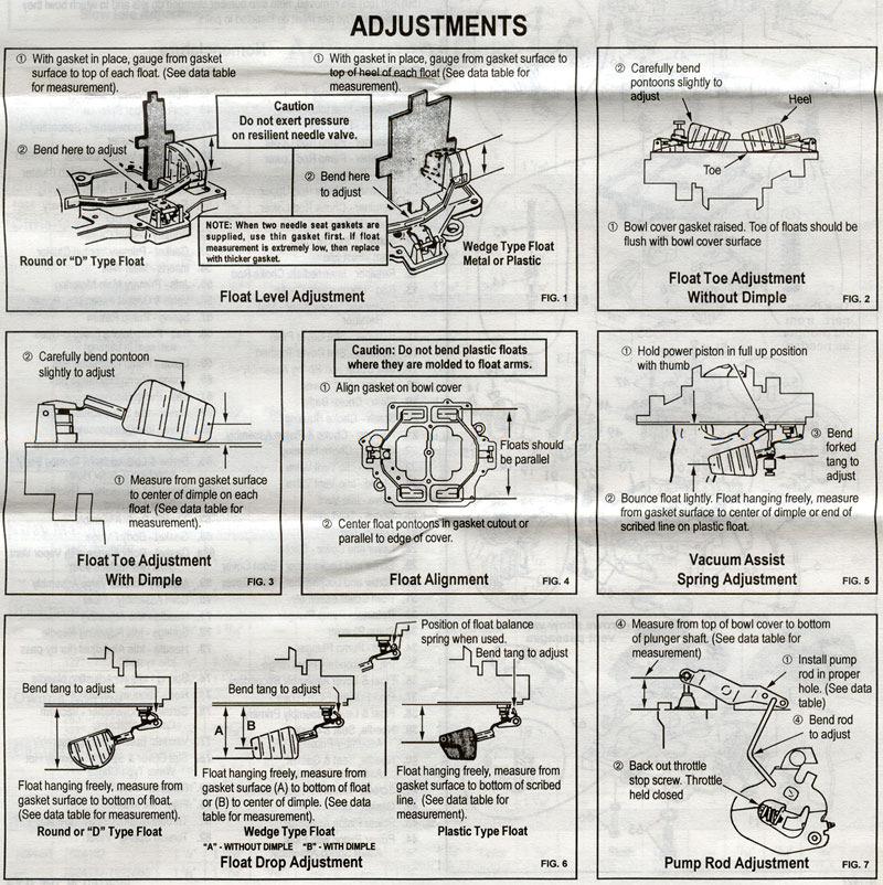
1 INSTRUCTION SHEET Rochester Carburetor Models 4G 4GC General Exploded View The general design and parts shown will vary to individual units covered on this instruction sheet. Disassembly Use the exploded view as a guide. The numerical sequence may generally be followed to disassemble unit far enough to permit cleaning and inspection. Note: Bowl cover mounted automatic choke models usually only require removal of stat cover or vacuum unit. Caution: If choke shaft requires removal, choke valve screw are staked over, and staking must be filed off before screws are turned. Hot water type stat covers should not be disassembled unless parts are being replaced, and should not be immersed in cleaner or solvent. Remove staking from bowl cover for easy removal of power piston assembly (43) or (44). When removing floats (36) and (38), mark each one as to the side it belongs. Note: (Primary side has pump circuit and choke valve). If main metering jets (50) and (55) are removed, note size number stamped on jets and from which bowl they are removed. The jets must be installed in pairs. Cleaning Cleaning must be done with carburetor disassembled. Soak parts long enough to soften and remove all foreign material. Use a carburetor cleaning solvent, lacquer thinner or denatured alcohol. Make certain the throttle body is free of all hard carbon deposits. Rinse off in suitable solvent. Blow out all passages in casting with compressed air and check carefully to insure thorough cleaning of obscure areas. Caution: Do not soak rubber, leather or plastic parts in solvent. NOTE: (78), (79) and (80) Water heated type choke stat cover may be removed from carburetor on engine to eliminate draining of coolant. (Leave water hoses connected). Reassembly Reassemble in reverse order of disassembly. Note special instructions and follow numerical outline in making adjustments. See other side. Special Instructions Plunger (33). Remove paper sleeve from leather cup if used. Flex leather outward slightly. Soak cup in gasoline, kerosene or oil for a few minutes prior to placing in carburetor. Needle and seat selection where two part numbers are supplied Use assembly with larger hole on the primary side. Needle and seat gasket selection refer to figure (1) Page 2 Power piston installation (43) or (44) lightly stake casting around washer When installing floats that use a float balance spring (46), be sure spring is between float tang and needle seat refer to figure (6) Page 2 Venturi cluster (48) (52) installation. The primary cluster contains pump discharge nozzles and is installed on the side with the pump well. Idle adjusting needles (71). Turn each needle in to seat lightly and then back out 1 ½ - 2 turns. Idle air screw (73) if used, turn into seat and back out 1 ½ - 2 turns. N-1427
2 Nomenclature Ref.No. Ref.No. 1. Fitting Fuel Inlet 45. Spring Power Piston 2. Gasket Fuel Inlet Fitting 46. Spring Float Balance 3. Screen Fuel Inlet 47. Screw & Lockwasher Secondary Venturi Cluster 4. Retainer Pump Rod Upper 48. Secondary Venturi Cluster 5. Retainer Pump Rod Lower 49. Gasket Secondary Venturi Cluster 6. Rod Pump 50. Jets Secondary Main Metering 7. Retainer Choke Rod Upper 51. Screw & Lockwasher Primary Venturi Cluster 8. Retainer Choke Rod Lower 52. Primary Venturi Cluster 9. Rod Choke 53. Gasket Primary Venduri Cluster 10. Screw Fast Idle Cam 54. Inserts Main Well 11. Cam Fast Idle 55. Jets Primary Main Metering 12. Retainer Intermediate Choke Rod 56. Valve & Gasket Assembly Power 13. Rod Intermediate Choke 57. Spring Pump Return 14. Screw and Lockwasher Stat Retainer 58. Ball Pump Intake (used in types with seat in casting) 15. Retainer Stat Cover Plain 59. Guide Pump Discharge Ball 16. Retainer Stat Cover Toothed 60. Spring Pump Discharge Ball 17. Stat Cover and Spring Assembly 61. Ball Pump Discharge 18. Gasket Stat Cover 62. Screw Idle Compensator Valve 19. Plate Choke Baffle 63. Valve Idle Compensator 20. Screw Choke Housing 64. Gasket Idle Compensator Valve 21. Housing Choke & Piston Assembly 65. Screw & Lockwasher Throttle Body Attaching (Center Hole) 22. Gasket Choke Housing 66. Screw & Lockwasher Throttle Body Attaching 23. Screw Idle Vent Valve 67. Throttle Body Assembly 24. Shield Idle Vent Valve 68. Gasket Body Flange 25. Valve Idle Vent 68a. Gasket Body Flange with Vapor Vent Slots (will replace#68) 26. Screw Trip Lever 69. Auxiliary Throttle Valve Assembly 27. Lever Trip 70. Bowl Assembly Float 28. Lever and Collar Choke 71. Needle Idle Adjusting 29. Screw and Lockwasher Bowl Cover 72. Springs Idle Adjusting Needle 30. Screw and Lockwasher Bowl Cover 73. Needle Idle Air Adjust (for by-pass idle system) 31. Bowl Cover Assembly 74. Spring Idle Air Adjusting Needle 32. Retainer Pump Plunger 75. Rod Vacuum Control 33. Pump Plunger 76. Screw & Lockwasher Vacuum Control Attaching 34. Boot Pump Plunger 77. Vacuum Break Control Assembly 35. Pin Secondary Float Hinge 78. Stat Cover & Spring Assembly Hot Water Type Choke 36. Float & Lever Assembly Secondary 79. Retainer Filter 37. Pin Primary Float Hinge 80. Filter Air Intake 38. Float & Lever Assembly Primary 81. Throttle Return Check Assembly 39. Needle, Seat & Gasket Assembly Primary 82. Torsion Spring Float 40. Needle, Seat & Gasket Assembly Secondary 41. Screen Needle & Seat Strainer 42. Gasket Bowl Cover 43. Power Piston Assembly 44. Power Piston with Float Assist Spring Assembly N-1427
3 N-1427
4
5
INSTRUCTION SHEET ROCHESTER CARBURETOR MODELS 4MC 4MV
 INSTRUCTION SHEET ROCHESTER CARBURETOR MODELS 4MC 4MV GENERAL EXPLODED VIEW THE GENERAL DESIGN AND PARTS SHOWN WILL VARY TO INDIVIDUAL UNITS COVERED ON THIS INSTRUCTION SHEET DISASSEMBLY Use exploded view
Performer Series Carburetor Rebuild Kit Catalog #1477 Models
 Please read these instructions carefully before attempting to rebuild your carburetor. Make sure to refer to your carburetor Owner s Manual for further information if need be. If you have any questions
Rebuild and Adjustment Manual for Models 2010, 2300, 4010, 4011, 4150, 4160, 4165, 4175, and 4500
 Rebuild and Adjustment Manual for Models 2010, 2300, 4010, 4011, 4150, 4160, 4165, 4175, and 4500 WARNING! These instructions must be read and fully understood before beginning installation. Failure to
Base Kit Rochester Tri Power Carb small parts kit contents:
 910-11589 Base Kit Rochester Tri Power Carb small parts kit contents: Installation of Rochester 2 GC Tri-Power Base Kit Modifications to center (primary) carb 1) Remove, disassemble, and clean carb as
CARBURETOR - HITACHI 2-BBL
 CARBURETOR - HITACHI 2-BBL 1986 Isuzu Trooper II 1986 Hitachi Carburetors HITACHI DCH340, DCR384, DFP340, DFP384 & DHP340 2-BARREL P UP & Trooper II DESCRIPTION Carburetor is a 2-barrel downdraft type
GENERAL DESCRIPTION ROCHESTER 4GC 4-JET CARBURETOR 6B PONTIAC SHOP MANUAL
 6B-56 1955 PONTIAC SHOP MANUAL GENERAL DESCRIPTION ROCHESTER 4GC 4-JET CARBURETOR The Rochester 4GC Carburetor for the 1955 Pontiac V -8 is essentially two 2 -J et carburetors in a single casting. The
AN EXPLANATION OF CIRCUITS CARTER YH HORIZONTAL CLIMATIC CONTROL CARBURETER
 AN EXPLANATION OF CIRCUITS CARTER YH HORIZONTAL CLIMATIC CONTROL CARBURETER The Carter Model YH carbureter may be compared with a Carter YF downdraft carbureter with the circuits rearranged to operate
CARTER DOWNDRAFT CARBURETOR Terraplane All Models. Technical Information
 CARTER DOWNDRAFT CARBURETOR 1934 Terraplane All Models Technical Information . Carter W-1 Downdraft Carburetors 1934 Terraplane Challenger, Model KS NOTE: Terraplane Models. Carburetor fitted with Anti-
HUDSON MOTOR CAR COMPANY
 HUDSON MOTOR CAR COMPANY 1935-1942 Carburetor Tune-up Manual ( for Hudson and Terraplane Models) Index Carter W-1 Downdraft 1935-1942 1 Carter W-1 Vacumeter Type 1938 Hudson 4 Carter WA-1 Vacumeter Type
TILLOTSON LTD., CLASH INDUSTRIAL ESTATE, TRALEE, CO. KERRY, IRELAND PHONE: FAX:
 TILLOTSON LTD., CLASH INDUSTRIAL ESTATE, TRALEE, CO. KERRY, IRELAND PHONE: +353 66 7121911 FAX: +353 66 7124503 e-mail: sales@tillotson.ie HU SERIES SERVICE MANUAL INTRODUCTION To keep apace of new market
Illustrated Parts List
 FORM MS 4183 10/31/2006 REPLACES FORM MS 9748 7/1997 FILE IN SECT. 2 OF SERVICE MANUAL 290700 Illustrated Parts List Model Series 290700 TYPE NUMBERS 0100, 0102, 0106, 0107, 0108, 0333, 0402, 0410. TO
Nikki Carburetor Vertical Models , ,
 Nikki Carburetor Vertical Models 280000, 310000, 330000 Disassemble Carburetor 1. Remove fuel bowl screws (A, Figure 56). Remove the fuel bowl (B) from the carburetor body. WARNING Before servicing the
Tillotson Tc3A Carburator
 Tillotson Tc3A Carburator 176 FUEL SYSTEMS - 5B-11 CENTER BOWL TYPE CARBURETOR Removal 1. Remove front cowl cover and wrap-around cowl. 2. Remove swivel link from lower carburetor. (Figure 2) 3. Loosen
A-PDF Split DEMO : Purchase from to remove the watermark
 5-18 FUEL AND LUBRICATION SYSTEM A-PDF Split DEMO : Purchase from www.a-pdf.com to remove the watermark Use a % size drill bit with a drill-stop to remove the pilot screw plug. Set the drill-stop 6 mm
FUEL SYSTEM (PUMP, CARBURETOR, TANK)
") FUEL SYSTEM 14-1 GROUP 14 FUEL SYSTEM (PUMP, CARBURETOR, TANK) CONTENTS PART 1 WWC3 Series Carbureter Page Disassembling the Carburetor 5 Inspection and Reassembly 7 Page Carburetor Adjustments. 10 Automatic
FUEL SYSTEM 14-1 GROUP 14 FUEL SYSTEM (PUMP, CARBURETOR, TANK) CONTENTS PART 1 WWC3 Series Carbureter Page Disassembling the Carburetor 5 Inspection and Reassembly 7 Page Carburetor Adjustments. 10 Automatic
Rochester Quadrajet Dodge
 Rochester Quadrajet Dodge ADJUSTMENTS Float Level EXTERNAL CHECK See Figure 1 Fig. 1: Float level external check for the Rochester Quadrajet 1. With the engine idling at normal operating temperature and
Illustrated Parts List to
 Illustrated Parts List Model Series 176400 to 176499 TYPE NUMBERS 0035, 0049, 0050, 0101, 0103, 0113, 0114, 0115, 0116. FORM MS 0419 9/97 REPLACES FORM MS 0419 5/97 FILE IN SECT. 2 OF SERVICE MANUAL 176400
Illustrated Parts List to
 TYPE NUMBERS 0022 through 0035, 0040 through 0062, 0070, 0076,0100, 0102, 0120 through 0125, 0307, 0318,0320, 0326, 0340 through 0366, 0370 through 0378, 0382, 0385, 0390, 0391, 0394, 0398, 0402, Illustrated
Illustrated Parts List to
 Illustrated Parts List Vanguard Model Series 161400 to 161499 TYPE NUMBERS 0010 through 0036, 0040, 0041, 0047, 0049, 0051, 0070, 0073, 0079 through 0085, 0090, 0101, 0110 through 0135, 0199. FORM MS 9877
5. FUEL SYSTEM 5-0 FUEL SYSTEM MXU 250R/300R
 5 FUEL SYSTEM 5 SERVICE INFORMATION------------------------------------------------ 5-2 TROUBLESHOOTING----------------------------------------------------- 5-3 FUEL TANK -----------------------------------------------------------------
CARBURETOR. Preliminary Check. Removal of DuraForce Carburetor
 Fuel Leaks From Carburetor (Leaking starts after running, stops after shutdown) Note: This condition which does NOT drain the fuel tank is called spit-back. Possible Causes Engine RPM out of proper range
TILLOTSON LTD., CLASH INDUSTRIAL ESTATE, TRALEE, CO. KERRY, IRELAND PHONE: FAX:
 TILLOTSON LTD., CLASH INDUSTRIAL ESTATE, TRALEE, CO. KERRY, IRELAND PHONE: +353 66 7121911 FAX: +353 66 7124503 e-mail: sales@tillotson.ie HS SERIES SERVICE MANUAL INTRODUCTION The demand for a miniature
Group 14 FUEL SYSTEM CONTENTS FUEL PUMP BED SERIES CARBURETORS
 FUEL SYSTEM 1 Group 14 FUEL SYSTEM CONTENTS FUEL PUMP Paragraph Page Fuel Pump Disassembly 7 5 Removal Cleaning and Inspection Assembly Operation (Fuel Pump) 5 4 Service Diagnosis 1 3 Fuel Pump Testing
TILLOTSON LTD., CLASH INDUSTRIAL ESTATE, TRALEE, CO. KERRY, IRELAND PHONE: FAX:
 TILLOTSON LTD., CLASH INDUSTRIAL ESTATE, TRALEE, CO. KERRY, IRELAND PHONE: +353 66 7121911 FAX: +353 66 7124503 e-mail: sales@tillotson.ie HR SERIES SERVICE MANUAL INTRODUCTION Tillotson has developed
Section VIII FUEL AND EXHAUST SYSTEM CONTENTS
 FUEL AND EXHAUST SYSTEM 1 Section VIII FUEL AND EXHAUST SYSTEM CONTENTS Page Fuel Pump 3 Servicing the Fuel Pump 4 The Vapor Separator 5 Service Diagnosis 6 Carburetor BBD-2685S Disassembly 7 Carburetor
SECTION 4 - FUEL SYSTEMS AND CARBURETION
 SECTION - FUEL SYSTEMS AND CARBURETION FUEL SYSTEMS - - - - - - - - - - - - - - - - - - - - - - - - - - - - - - - - - - - - - - - - - - - - - - - - - - - - - - - - - - - - - -62 FUEL PUMP - - - - - - -
~. a~' ~ ( I o~~~ 4-0. ~Sj~' AO~ i/~ CB1000C (ij)aon'da in-ib) ~ "" ~ ~!~~P. ~ J N m (6-12 kg-em,
aon'da in-ib) ~ ~ ~!~~P. ~ J N m (6-12 kg-em,") e V ~. a~' ~ I ~ J C t \"" 8.0- ( I o~~~ ~ "" ~ ~. ~!~~P. C8 0 & 0,-t. ~ CB1000C (ij)aon'da 0.6-1.2 N m (6-12 kg-em, 5-10 in-ib) 4-0 / 4.0-6.0 N m (40-60 kg-em, 35-52 in-i b) t$ "'07~ / c;:::/ j ~Sj~'
e V ~. a~' ~ I ~ J C t \"" 8.0- ( I o~~~ ~ "" ~ ~. ~!~~P. C8 0 & 0,-t. ~ CB1000C (ij)aon'da 0.6-1.2 N m (6-12 kg-em, 5-10 in-ib) 4-0 / 4.0-6.0 N m (40-60 kg-em, 35-52 in-i b) t$ "'07~ / c;:::/ j ~Sj~'
13. FUEL SYSTEM/CARBURETOR/
 13 FUEL SYSTEM/CARBURETOR/FUEL PUMP FUEL SYSTEM --------------------------------------------------------- 13-1 SCHEMATIC DRAWING ---------------------------------------------- 13-2 OPERATION OF CARBURETOR
TILLOTSON LTD., CLASH INDUSTRIAL ESTATE, TRALEE, CO. KERRY, IRELAND PHONE: FAX:
 TILLOTSON LTD., CLASH INDUSTRIAL ESTATE, TRALEE, CO. KERRY, IRELAND PHONE: +353 66 7121911 FAX: +353 66 7124503 e-mail: sales@tillotson.ie SERIES SERVICE MANUAL INTRODUCTION The gasoline engine industry
Illustrated Parts List to
 Illustrated Parts List Model Series 124800 to 124899 FORM MS-2436-9/94 REPLACES FORM MS-2436-10/93 FILE IN SECT. 2 OF SERVICE MANUAL 124800 to 124899 TYPE NUMBERS 0106, 0206 through 0284, 0406 through
rev 1_09/20/2017 PS-35C EA3500SR
 C 1 Tank, Handle 5 7 6 8 17 9 1 2 10 11 12 13 18 19 20 3 21 4 22 23 14 16 2 1 Tank, Handle 1 1 168507-3 TANK CAP COMPLETE 1 1 INC. 2 1 2 213080-9 O RING 29.5 1 1 1 3 163447-0 GASOLINE FILTER 1 1 1 4 195757-7
CHAPTER 4. CARBURETION
 CHAPTER 4. CARBURETION CARBURETOR... 4l SECTIONAL VIEW.... 42 REMOVAL... 44 DISASSEMBLY... 44 INSPECTION... 47 ASSEMBLY... 48 INSTALLATION....4l 1 ADJUSTMENT....4l 1 1 C A R B U R E T O R CARBURETOR @connection
7. FUEL SYSTEM ('04 - '05)
") 7. FUEL SYSTEM ('04 - '05) SYSTEM COMPONENTS 7-2 CARBURETOR DISASSEMBLY 7-81 SERVICE INFORMATION 7-3 CARBURETOR ASSEMBLY 7-14 TROUBLESHOOTING 7-4 CARBURETOR INSTALLATION 7-21 AIR CLEANER HOUSING 7-5 PILOT
7. FUEL SYSTEM ('04 - '05) SYSTEM COMPONENTS 7-2 CARBURETOR DISASSEMBLY 7-81 SERVICE INFORMATION 7-3 CARBURETOR ASSEMBLY 7-14 TROUBLESHOOTING 7-4 CARBURETOR INSTALLATION 7-21 AIR CLEANER HOUSING 7-5 PILOT
CARBURETION. Carburetor Identification. Models , , , , , , , , , , ,
 Carburetor Identification Models 110400, 110600, 111400, 111600, 113400, 120400, 120600, 121400, 121600, 122600, 123400, 123600 Models 28S700, 311700 Service Carburetor Briggs & Stratton/Walbro LMS Models
5. FUEL SYSTEM 5-0 FUEL SYSTEM UXV 500
 5 FUEL SYSTEM 5 SERVICE INFORMATION------------------------------------------------ 5-02 TROUBLESHOOTING----------------------------------------------------- 5-03 FUEL TANK -----------------------------------------------------------------
Illustrated Parts List to 83499
 Illustrated Parts List Model Series 83400 to 83499 TYPE NUMBERS 0101, 0105, 0106. FORM MS 5308 5/97 REPLACES FORM MS 5308 1/95 FILE IN SECT. 2 OF SERVICE MANUAL 83400 to 83499 TO FIND THE CORRECT NUMBER
Illustrated Parts List to
 FORM MS-2442-9/93 REPLACES FORM MS-2442-11/92 FILE IN SECT. 2 OF SERVICE MANUAL Illustrated Parts List Industrial/Commercial Model Series TYPE NUMBERS 0101 through 0104, 0116 through 0120, 0122 through
CARBURETION. Flo-Jet Carburetors. One Piece. One-Piece Flo-Jet. Main Jet Adjustment N eedle
 One Piece One-Piece Flo-Jet The small One-Piece Flo-Jet carburetor is illustrated in Fig. 122 and was used on early Model 170700. These are float feed carburetors with adjustable orifice main jet needle
235/245400, , 28N
 Models 235/245400, 287000, 28N thru W, 310/312/313700 These carburetors have a fixed high speed main jet with adjustable idle, Fig 183. The different carburetors are identified as LMT 1 and up. The letters
Illustrated Parts List. 9K400 to 9K499
 Illustrated Parts List Model Series TYPE NUMBERS 0022, 0023, 0024, 0115, 0116, 0117, 0118, 0119. FORM MS 2223 2Q 6/2000 REPLACES FORM MS 2223 1Q 1/2000 FILE IN SECT. 2 OF SERVICE MANUAL TO FIND THE CORRECT
DESCRIPTION FUEL AND VACUUM PUMP REMOVE AND REPLACE FUEL PUMP-OVERHAUL 6B PONTIAC SHOP MANUAL. S. Install battery and connect cables.
 6B-74 1955 PONTIAC SHOP MANUAL DESCRIPTION FUEL AND VACUUM PUMP All models are equipped with a combination fueland double acting vacuum pump operated by an eccentric bolted to the front end of the engine
FUEL SYSTEM/CARBURETOR/FUEL PUMP
 13 FUEL SYSTEM/CARBURETOR/FUEL PUMP FUEL SYSTEM-------------------------------------------------------------------------------------13-1 SCHEMATIC DRAWING-------------------------------------------------------------------------13-2
Illustrated Parts List Vanguard to Compliance
 Non-Compliance Illustrated Parts List Vanguard Model Series 104700 to 104799 FORM MS-9878 7/93 REPLACES FORM MS-9878 5/92 FILE IN SECT. 2 OF SERVICE MANUAL 104700 to 104799 Compliance TYPE NUMBERS 0101,
SECTION 4 - FUEL/LUBRICATION/COOLING
 For Arctic Cat Discount Parts Call 606-678-9623 or 606-561-4983 SECTION 4 - FUEL/LUBRICATION/COOLING 4 TABLE OF CONTENTS Carburetor Specifications... 4-2 Carburetor Schematic... 4-2 Carburetor... 4-3 Cleaning
FU-1 FUEL SYSTEM. Page PRECAUTIONS... TROUBLESHOOTING... ON-VEHICLE INSPECTION...
 FU-1 FUEL SYSTEM PRECAUTIONS... TROUBLESHOOTING... ON-VEHICLE INSPECTION... CARBURETOR FUEL PUMP... Page FU-2 FU-2 FU-3 FU-4 FU-28 FU-2 FUEL SYSTEM - Precautions, Troubleshooting PRECAUTIONS 1. Before
Illustrated Parts List Industrial/Commercial to
 FORM MS-9479 6/95 REPLACES FORM MS-9479 10/94 FILE IN SECT. 2 OF SERVICE MANUAL 402700 to 402799 Illustrated Parts List Industrial/Commercial Model Series 402700 to 402799 TYPE NUMBERS 1115 through 1117,
FUEL SYSTEM (PUMP. CARBURETOR, TANK)
") FUEL SYSTEM (PUMP, CARBURETOR, TANK) 14-1 GHOUP 14 FUEL SYSTEM (PUMP. CARBURETOR, TANK) FUEL PUMP ' CONTENTS Cleaning Fuel Pump Parts. 6 Disassembling the Fuel Pump 6 Reassembling the Fuel Pump 6 Testing
FUEL SYSTEM (PUMP, CARBURETOR, TANK) 14-1 GHOUP 14 FUEL SYSTEM (PUMP. CARBURETOR, TANK) FUEL PUMP ' CONTENTS Cleaning Fuel Pump Parts. 6 Disassembling the Fuel Pump 6 Reassembling the Fuel Pump 6 Testing
Illustrated Parts List to
 Illustrated Parts List Model Series 138400 to 138499 FORM MS 2111 2Q 6/2000 REPLACES FORM MS 2111 7/99 FILE IN SECT. 2 OF SERVICE MANUAL 138400 to 138499 TYPE NUMBERS 0035, 0038, 0042, 0047, 0084, 0120,
Illustrated Parts List. 28R700 to 28R799
 Illustrated Parts List Model Series TYPE NUMBERS 0140, 0148, 0637, 0648, 1028, 1114, 1140, 1148, 1150. FORM MS 4990 2Q 9/2000 FORM MS 4990 10/99 FILE IN SECT. 2 OF SERVICE MANUAL TO FIND THE CORRECT NUMBER
Mfg. No: 49T G1
 Parts Manual Mfg. No: 49T877-0004-G1 Copyright Briggs and Stratton. All Rights reserved 28-Feb-2018 Model Components Table Of Contents Page Blower Housing, Air Cleaner............................................................................
Hudson-Essex. Service Manual Supplement. Hudson Cars 750,001 up
 1 9 2 6 Hudson-Essex Service Manual 1927 Supplement Hudson Cars 750,001 up Hudson Rear Axle (Cars numbered 750,001 and upward) Brakes (Cars numbered 750,001 and upward) See page 18 Transmission Group
Diagnostic Dilemmas: Servicing Quadrajet Carburetors
 Tech Topics Diagnostic Dilemmas: Servicing Quadrajet Carburetors By Gary Goms email Technical Contributor May 01, 2008 Email Print Comment Sign up for enewsletter Bookmark this website Introduced at the
Illustrated Parts List. Model Series. AIR COOLED Horizontal Shaft
 Illustrated Parts List Model Series 613400 AIR COOLED Horizontal Shaft FORM MS6154 REV C -- 12/14/2012 REPLACE FORM MS6154 REV B -- 06/10/2010 FILE IN SECT. 2 OF SERVICE MANUAL 613400 TYPE NUMBERS 0035,
FUEL SYSTEM GROUP 14 CONTENTS GENERAL INFORMATION SERVICING CARBURETOR. AUTOMATIC CHOKE (Well Type) CLEANING CARBURETOR PARTS
 CLEANING CARBURETOR PARTS") FUEL SYSTEM GROUP 14 CONTENTS Page AVS SERIES CARBURETOR 26 HOLLEY 2200 SERIES CARBURETOR BBD SERIES CARBURETOR 6 HOLLEY 4160 SERIES CARBURETOR FUEL PUMP 55 THROTTLE LINKAGE FUEL TANKS 57 SPECIFICATIONS
FUEL SYSTEM GROUP 14 CONTENTS Page AVS SERIES CARBURETOR 26 HOLLEY 2200 SERIES CARBURETOR BBD SERIES CARBURETOR 6 HOLLEY 4160 SERIES CARBURETOR FUEL PUMP 55 THROTTLE LINKAGE FUEL TANKS 57 SPECIFICATIONS
Illustrated Parts List. Model Series AIR COOLED
 FORM MS6154--06/10/2010 REPLACE FORM MS6154--03/06/2010 FILE IN SECT. 2 OF SERVICE MANUAL Illustrated Parts List Model Series AIR COOLED TYPE NUMBERS 0035, 0038, 0048, 0076, 0078, 0079, 0100, 0111, 0113,
Illustrated Parts List to
 FORM MS-5838-9/94 REPLACES FORM MS-5838-10/93 FILE IN SECT. 2 OF SERVICE MANUAL 122700 to 122799 Illustrated Parts List Model Series 122700 to 122799 TYPE NUMBERS 0101 through 0108, 0115 through 0213,
CARBURETOR SERVICE INFORMATION TROUBLESHOOTING THROTTLE VALVE DISASSEMBLY THROTTLE VALVE INSTALLATION...
 11 CARBURETOR SERVICE INFORMATION... 11-2 TROUBLESHOOTING... 11-2 THROTTLE VALVE DISASSEMBLY... 11-3 THROTTLE VALVE INSTALLATION... 11-4 CARBURETOR REMOVAL... 11-5 AUTO BYSTARTER... 11-6 FLOAT CHAMBER...
12. CARBURETOR/FUEL PUMP
 12 CARBURETOR/FUEL PUMP SERVICE INFORMATION... 12-2 TROUBLESHOOTING... 12-2 THROTTLE VALVE DISASSEMBLY... 12-3 THROTTLE VALVE INSTALLATION... 12-4 CARBURETOR REMOVAL... 12-5 AUTO BYSTARTER... 12-6 FLOAT
Illustrated Parts List to 93499
 TYPE NUMBERS 0010, 0011, 0015, 0024, 0035 through 0041, 0049, 0060, 0136 through 0141, 0144 through 0155, 0157, 0158, 0168, 0169, 0172, 0174, Illustrated Parts List Model Series 93400 to 93499 FORM MS
Illustrated Parts List to
 TYPE NUMBERS 0101, 0102, 0106, 0108, 0109, 0115 through 0224, 0415, 0418, 0467, 0468, 0601 through 0683, 3101 through 3108, 3110 through 3163, 3167 through 3181. Illustrated Parts List Model Series 124700
Illustrated Parts List
 FORM MS 2263 12/08/2004 REPLACES FORM MS 2263 03/20/2004 FILE IN SECT. 2 OF SERVICE MANUAL Illustrated Parts List Model Series TYPE NUMBERS 0001 through 1421. TABLE OF CONTENTS Air Cleaners........................
LF2WP (-CA) WATER PUMP EXPLODED VIEWS & PARTS LISTS
 WATER PUMP EXPLODED VIEWS & PARTS LISTS") LFWP (-CA) WATER PUMP EXPLODED VIEWS & PARTS LISTS 0 Industrial Park Road Van Buren, AR 9 (8) - www.lifanpowerusa.com E- CRANKCASE ASSY 8 9 0 /8F /8F GB/T 80/8F 00/8F-E /8F 9/8F /8F GB/T 80/8F GB/T. /8F
LFWP (-CA) WATER PUMP EXPLODED VIEWS & PARTS LISTS 0 Industrial Park Road Van Buren, AR 9 (8) - www.lifanpowerusa.com E- CRANKCASE ASSY 8 9 0 /8F /8F GB/T 80/8F 00/8F-E /8F 9/8F /8F GB/T 80/8F GB/T. /8F
This file is available for free download at
 This file is available for free download at http://www.iluvmyrx7.com This file is fully text-searchable select Edit and Find and type in what you re looking for. This file is intended more for online viewing
2. Disconnect the accelerator control cable and the cruise control cable from the throttle body. 3. Disconnect the vacuum hose from the throttle body.
 2002 Silverado K 4WD Applies to: 4.8L, 5.3L, and 6.0L Report a problem with this article Removal Procedure 1. Remove the air intake duct. Refer to Air Cleaner Resonator Outlet Duct Replacement. 2. Disconnect
Illustrated Parts List
 FORM MS 54 08/11/2004 REPLACES FORM MS 54 11/14/2002 FILE IN SECT. 2 OF SERVICE MANUAL 311700 Illustrated Parts List Model Series 311700 TYPE NUMBERS 0005 through 0209. TABLE OF CONTENTS Air Cleaner.........................
Introduction WISCONSIN ROBIN WR-WOI-21 OPM REV DATE: This catalog is designed to identify Wisconsin Robin parts.
 WISCONSIN ROBIN WR-WOI- OPM REV DATE: 0- Introduction This catalog is designed to identify Wisconsin Robin parts. When ordering parts, it is always advisable to list the engine model, specification number
CHAPTER 4 FUEL SYSTEM
 CHAPTR 4 FUL SYSTM FUL SYSTM... 4-1 XPLODD DIAGRAM... 4-1 FUL LIN... 4-2 RMOVAL... 4-3 CLANING AND INSPCTION... 4-3 FUL TANK... 4-3 FUL MTR COMPLT... 4-4 PRIMING PUMP... 4-4 FUL FILTR... 4-4 FUL JOINTS...
Reproduction. Not for. Illustrated Parts List 49T800. Model Series TYPE NUMBERS 0001 THROUGH 0021.
 FORM MS10496 REV C 02/05/2016 REPLACES FORM MS10496 REV B 04/22/2014 FILE IN SECT. 2 OF SERVICE MANUAL Illustrated Parts List Model Series TYPE NUMBERS 0001 THROUGH 0021. PRINTED IN U.S.A. COPYRIGHT by
11. CARBURETOR 11-0 CARBURETOR ZX / SCOUT 50
 11 CARBURETOR SERVICE INFORMATION... 11-2 TROUBLESHOOTING... 11-2 THROTTLE VALVE DISASSEMBLY... 11-3 THROTTLE VALVE INSTALLATION... 11-4 CARBURETOR REMOVAL... 11-5 AUTO BYSTARTER... 11-6 FLOAT CHAMBER...
4. FUEL SYSTEM 4-0 FUEL SYSTEM NEXXON 50
 4 FUEL SYSTEM SERVICE INFORMATION ------------------------------------------------ 4-2 TROUBLESHOOTING----------------------------------------------------- 4-3 AIR CLEANER REMOVAL -----------------------------------------------
Illustrated Parts List to
 FORM MS-9491 6/94 REPLACES FORM MS-9491 8/93 FILE IN SECT. 2 OF SERVICE MANUAL 404700 to 404799 Illustrated Parts List Model Series 404700 to 404799 TYPE NUMBERS 1200 through 1207, 1211 through 1214, 1400,
Illustrated Parts List 9K400
 FORM MS 2223 05/17/2004 REPLACES FORM MS 2223 10/16/2003 FILE IN SECT. 2 OF SERVICE MANUAL 9K400 Illustrated Parts List Model Series 9K400 TYPE NUMBERS 0022 through 0119. TABLE OF CONTENTS Air Cleaner.........................
S/N 1H019H - 1H310H Page 1 of 33 46" Cutting Deck Assembly
 1180 S/N 1H019H - 1H310H Page 1 of 33 46" Cutting Deck Assembly 1180 S/N 1H019H - 1H310H Page 2 of 33 46" Cutting Deck Assembly 1 17982 1 S Reinforcement Spindle Plate 2 618-0430 1 S Spindle Assembly w/
Illustrated Parts List to
 Illustrated Parts List Model Series TYPE NUMBERS 0027, 0031, 0117, 0118, 0130, 0131, 0133 through 0137. FORM MS 8696 6/98 REPLACES FORM MS 8696 10/97 FILE IN SECT. 2 OF SERVICE MANUAL TO FIND THE CORRECT
Illustrated Parts List
 FORM MS 0670 3C 8/2001 REPLACES FORM MS 0670 2Q 11/2000 FILE IN SECT. 2 OF SERVICE MANUAL Illustrated Parts List Model Series TYPE NUMBERS 0042 through 1256. For Use On Engines Built Before Date Code 01070100.
Illustrated Parts List. Model Series. TYPE NUMBERS 0035 through TABLE OF CONTENTS
 Illustrated Parts List Model Series TYPE NUMBERS 0035 through 0563. TABLE OF CONTENTS FORM MS--6359--08/04/2009 REPLACES FORM MS--6359--10/07/2008 FILE IN SECT. 2 OF SERVICE MANUAL Air Cleaner... 5 Alternator...
Illustrated Parts List. Model Series 12D100. TYPE NUMBERS 0001 through TABLE OF CONTENTS
 Illustrated Parts List Model Series 12D100 TYPE NUMBERS 0001 through 0940. TABLE OF CONTENTS FORM MS3399 REV P 08/06/2014 REPLACES FORM MS3399 REV N 10/03/2012 FILE IN SECT. 2 OF SERVICE MANUAL 12D100
JOB AID INTRODUCTION TOOLS REQUIRED: GC160 GC190 GS190 GCV160 GCV190 GSV160 GSV190 CARBURETOR CLEANING
 JOB AID GC160 GC190 GS190 GCV160 GCV190 GSV160 GSV190 CARBURETOR CLEANING INTRODUCTION Service engineering has discovered that many GCV carburetors returned for warranty were improperly cleaned. Eighty
Illustrated Parts List to
 Illustrated Parts List Model Series 171400 to 171499 TYPE NUMBERS 0035 through 0131, 0235, 0249, 0270, 0300 through 0308, 0435 through 0470, 0500 through 0505, 0520 through 0535, 1035, 1049, 1070, 1100,
365-SUB Engine : Engine Assembly 365-SUB [1/1] Page 1 of 5
![365-SUB Engine : Engine Assembly 365-SUB [1/1] Page 1 of 5](/thumbs/91/105185559.jpg "365-SUB Engine : Engine Assembly 365-SUB [1/1] Page 1 of 5") Page 1 of 5 1 951-11012 Bolt 2 951-11054 Valve Cover 2 951-11054 1 Valve Cover 3 731-07059 Breather Hose 4 726-04101 Hose Clamp 6 N/A 1 Intake Valve Spring Seat 7 751-11124 Pivot Locking Nut 7 751-11124
Page 1 of 5 1 951-11012 Bolt 2 951-11054 Valve Cover 2 951-11054 1 Valve Cover 3 731-07059 Breather Hose 4 726-04101 Hose Clamp 6 N/A 1 Intake Valve Spring Seat 7 751-11124 Pivot Locking Nut 7 751-11124
Illustrated Parts List
 FORM MS 6217 7C 1/2003 REPLACES FORM MS 6217 3C 2/2001 FILE IN SECT. 2 OF SERVICE MANUAL Illustrated Parts List Model Series TYPE NUMBERS 0023 through 0242. For Use On Engines Built Before Date Code 03010100
CARBURETOR REBUILD KIT (Vacuum Secondary) Models Demon Carburetors & Holley Model 4160 LIT704
 Models Demon Carburetors & Holley Model 4160 LIT704") CARBURETOR REBUILD KIT 190000 (Vacuum Secondary) Models Demon Carburetors & Holley Model 4160 LIT704 INSTRUCTIONS: Before getting to the actual rebuild, it should be noted that the carbs shown here are
CARBURETOR REBUILD KIT 190000 (Vacuum Secondary) Models Demon Carburetors & Holley Model 4160 LIT704 INSTRUCTIONS: Before getting to the actual rebuild, it should be noted that the carbs shown here are
PARTS LIST. Craftsman 5.5 HP Snow Thrower Model
 24 Craftsman 5.5 HP Snow Thrower Model 24.88355 1. 31-2635 Snow Removal Tool Mount 2. 684-0405 Impeller Assembly, 12 Dia. 3. 10-034 Hex Screw, 3/8-16, 1.5, Gr5 4. 10-0451 Bolt, Carriage, 5/16-18,.50 Gr1
Illustrated Parts List
 FORM MS 56 08/11/2004 REPLACES FORM MS 56 11/14/2002 FILE IN SECT. 2 OF SERVICE MANUAL 312700 Illustrated Parts List Model Series 312700 TYPE NUMBERS 0101 through 01. TABLE OF CONTENTS Air Cleaner.........................
Illustrated Parts List
 FORM MS 0323 6/27/2003 REPLACES FORM MS 0323 4C 9/2001 FILE IN SECT. 2 OF SERVICE MANUAL 93400 Illustrated Parts List Model Series 93400 TYPE NUMBERS 0010 through 1278. TABLE OF CONTENTS Air Cleaner.........................
Illustrated Parts List
 FORM MS 2264 07/20/2005 REPLACES FORM MS 2264 03/04/2005 FILE IN SECT. 2 OF SERVICE MANUAL 350700 Illustrated Parts List Model Series 350700 TYPE NUMBERS 0034 through 1171. TABLE OF CONTENTS Air Cleaner.........................
Checking Solenoid Plunger Travel
 1985 Chevy Truck EL Camino V8-305 5.0L Page 1 Carburetor: Adjustments Carburetor Calibration E2M & E4M Series Mixture Control Solenoid Plunger Travel Checking Solenoid Plunger Travel OTE: Mixture control
Illustrated Parts List to
 Illustrated Parts List Model Series TYPE NUMBERS 0111 through 0199, 0200 through 0213, 0300 through 0353, 1345,1353, 2035 through 2073, 2135 through 2174, 4001 through 4090, 5001, 5005, 5006, 5035 through
5. FUEL SYSTEM FUEL SYSTEM 5-0
 5 FUEL SYSTEM 5-0 SERVICE INFORMATION GENERAL INSTRUCTIONS SERVICE INFORMATION...5-1 CARBURETOR INSTALLATION...5-9 TROUBLESHOOTING...5-1 PILOT SCREW ADJUSTMENT...5-10 CARBURETOR REMOVAL...5-2 AUTO BYSTARTER...5-3
ZAMA CUBE CARBURETOR DISASSEMBLY AND SERVICE
 ZAMA CUBE CARBURETOR DISASSEMBLY AND SERVICE MIXTURE SCREWS Remove idle and main mix ture screw. Inspect each screw for damage, especially the needle points which should have no deformation of the tapered
Illustrated Parts List. Model Series. TYPE NUMBERS 0113 through TABLE OF CONTENTS
 Illustrated Parts List Model Series 219800 TYPE NUMBERS 0113 through 4389. TABLE OF CONTENTS FORM MS5709 REV P 11/08/2012 REPLACES FORM MS5709 REV N 04/24/2012 FILE IN SECT. 2 OF SERVICE MANUAL 219800
FUEL SYSTEM CIRCUIT D'ESSENCE KRAFTSTOFFSYSTEM
 CIRCUIT D'ESSENCE KRAFTSTOFFSYSTEM 41 FUEL SYSTEM SERVICE INFORMATION TROUBLESHOOTING FUEL TANK AIR CLEANER CARBURETOR REMOVAL VACUUM CHAMBER FLOAT CHAMBER 4-1 PILOT SCREW 4-2 CARBURETOR SEPARATION 4-3
Illustrated Parts List 28N700
 FORM MS 0148 09/14/2004 REPLACES FORM MS 0148 4C 12/1/2003 FILE IN SECT. 2 OF SERVICE MANUAL Illustrated Parts List Model Series TYPE NUMBERS 0026 through 1205. TABLE OF CONTENTS Air Cleaner.........................
Illustrated Parts List. Model Series. TYPE NUMBERS 0110 through TABLE OF CONTENTS
 Illustrated Parts List Model Series TYPE NUMBERS 0110 through 5159. TABLE OF CONTENTS FORM MS10113 REV G 07/12/2012 REPLACES FORM MS10113 REV F 02/07/2012 FILE IN SECT. 2 OF SERVICE MANUAL Air Cleaner...
TILLOTSON LTD., CLASH INDUSTRIAL ESTATE, TRALEE, CO. KERRY, IRELAND PHONE: FAX:
 TILLOTSON LTD., CLASH INDUSTRIAL ESTATE, TRALEE, CO. KERRY, IRELAND PHONE: +353 66 7121911 FAX: +353 66 7124503 e-mail: sales@tillotson.ie SERIES PARTS LIST Last update: JULY 2000 Illustration of basic
Craftsman Snow Thrower Model PARTS LIST
 Craftsman Snow Thrower Model 24.881900 PARTS LIST 11 13 3 2 24 9 1 18 4 2 1 20 23 1 14 1 9 2 4 4 4 3 28 8 3 4 3 39 0 3 43 38 2 48 2 42 1 41 40 49 4 44 31 4 31 21 29 34 9 19 10 32 22 2 Craftsman Snow Thrower
4. FUEL SYSTEM CK 1 4-0
 4 4 4-0 SERVICE INFORMATION... 4-1 FLOAT LEVEL INSPECTION... 4-5 TROUBLESHOOTING... 4-2 CARBURETOR INSTALLATION... 4-6 THROTTLE VALVE DISASSEMBLY... 4-3 THROTTLE VALVE ASSEMBLY... 4-6 CARBURETOR REMOVAL...
CARBURETOR ROUND SLIDE 2 STROKE ENGINES
 ROUND SLIDE STROKE ENGINES The motorcycle carburetor is a very touchy device that can cause all kinds of trouble if mishandled or neglected. Our experience indicates that most of the carburetors sent under
GROUP 14 - FUEL BRACKET SEAL \ LEVER RETAINER BY NAME ONLY - ORDER BY DESCRIPTION NUT AND WASHER
 FUEL 1963 PASSENGER CAR PARTS CATALOG Page 14-1 CLIP 14-13-3 SHAFT 14-11-1 SPRING 14-06-1 INSULATOR14-11-30 GROUP 14 - FUEL BRACKET 14-11-20 SEAL14-11-4 \ LEVER 14-11-28 RETAINER 14-13-5 C L I P - ^ ^
Illustrated Parts List. Model Series 21A900. TYPE NUMBERS 0101 through TABLE OF CONTENTS
 Illustrated Parts List Model Series TYPE NUMBERS 0101 through 0199. TABLE OF CONTENTS FORM MS--5069--03/17/2009 REPLACES FORM MS--5069--06/17/2008 FILE IN SECT. 2 OF SERVICE MANUAL Air Cleaner... 7 Alternator...