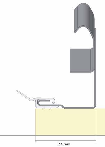
manual GB rev.0 Feb-09 RS200 Hardware system for residential (garage) overhead doors Built-in height 200mm, springs in front
|
|
|
- Francine Harrell
- 5 years ago
- Views:
Transcription
 overhead doors Built-in height")

1 RS200 Hardware system for residential (garage) overhead doors Built-in height 200mm, springs in front INSTALLATION / MAINTENANCE / USAGE All rights reserved. FlexiForce
2 ATTENTION! GENERAL WARNING! To install, use and maintain this door system safely, a number of precautions must be taken. For the safety of all concerned, pay heed to the warnings and instructions given below! If in doubt, contact your supplier. SPECIAL SAFETY WARNINGS OR REMARKS IN THIS MANUAL ARE INDICATED WITH THIS SYMBOL. READ THESE WARNINGS CAREFULLY! This manual has been written for use by experienced fitters and as such is not suitable for d.i.y. purposes or for use by trainee fitters. This manual describes the installation of the hardware set components, door sections (panels) and refers to installation manuals of the electrical operator. Be sure to supplement this manual if needed with instructions for any additional components not described in this manual. Before starting, read this manual carefully! Certain components may be sharp or have jagged edges. As such you are advised to wear safety gloves. All the components which have been supplied are designed for use with this specific overhead door. Replacement or adding additional components may have an adverse effect on the safety of, and the guarantee on, the door. Also the CE-approval which has been granted to this door will be cancelled when components are changed or installation is not done according to this manual! Installer is responsible for this. Ensure that there is sufficient light during installation. Remove obstacles and dirt. Make sure that there is no one else present other than the fitters. Other people (children!) may get in the way or endanger themselves during the installation. GUARANTEE, CONDITIONS AND TERMS The general terms and conditions of delivery and payment issued by the Metaalunie and designated as METAALUNIE CONDITIONS are fully applicable to all our quotations, contracts and their implementation. We expressly reject all other terms and conditions. On request we will send you a copy of these terms and conditions free of charge. A copy may also be downloaded from our website. FlexiForce strives to deliver 100 % in conformance with the order. In practice, in spite of all our controls, this is not always possible. However we will rectify any errors as quickly as possible, in order to minimise the inconvenience caused to you or the user. As such, it is important that you inform us as soon as possible about any problem with the delivery (include the order number and week of production) and give us the opportunity to offer a suitable solution. FlexiForce will only reimburse third party costs if we have given explicit permission for this in advance. The reimbursement is based on normal rates and travelling expenses over distances of 1 hour away at most. For large-scale projects we strongly advise you to first install 1 door completely before installing the other doors. In this way, any errors can be detected early on and rectified comparatively cheaply. This manual does not confer any rights. Technical modifications may be made without written notice. FlexiForce has endeavoured to design and put together this hardware set in conformance with the applicable CE-norms. However, we recommend to check our configuration against any local national specification. 2


3 FlexiForce has applied the mandated INITIAL TYPE TESTING for doors described in this manual, at the SP-Institute in Sweden (as Notified Body Nr. 0402). The INITIAL TYPE TESTING REPORT that has been rewarded, can be transferred to the door producing company. This is needed to complete your CE files according to product standard EN Contact FlexiForce for acquiring this report. APPLICATION RANGE FlexiForce has developed a new hardware system for garage overhead doors. The system includes the following features: Suitable for single and double garages, Wmax = mm, Hmax = mm. For double doors, the horizontal track set can be reinforced with side plate RX560L/R Advised max door weight is 165 kg. Each spring break device is approved to 125kg. CE approved when selecting the proper FlexiForce components. We wish you every success with the installation of this hardware set. If anything is unclear or should you have queries, you should of course contact Flexi-Force B.V. or your supplier. This set has to be completed with the assembled door sections. Panels brands and types according to the list of approved panels. NB! FlexiForce has introduced a new system for shaft installation, so called SUPERCLICK. There is a separate manual available for this system (attachment). In this manual, the SuperClick system is marked with this sign: NB! FlexiForce recommends to apply our light hardware range for garage doors. In this manual only light components are selected. Attention! In this set, the fixing material required to install the track set to the building is not included. It is the responsibility of the qualified door installer to make sure that the building (stone, concrete, wood, etc.) is strong enough at the points of fixation to ensure a reliable construction. The door installer has to select proper fixing materials. RECOMMENDED ADDITIONAL MANUALS 3

4 IN THIS MANUAL: - Attention, general warnings 2 - Guarantee, terms and conditions 2 - Application range 3 - Recommended additional manuals 3 - Tools for correct and rapid assembly 5 - Applied fixation materials 5 - RS200 System overview 6 - Installing vertical track system 7 - Installing horizontal track system 8 - Shaft system installation 11 - Panel <> Hardware installation 14 - Cables & Torsion springs 17 - Finishing the door 19 - Optional: E-operation 23 - Panel assembly 24 - Troubleshooting 27 - Dismantling the overhead door 28 - Maintenance and replacement of parts 29 4
 2 blocks of ca.")
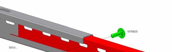
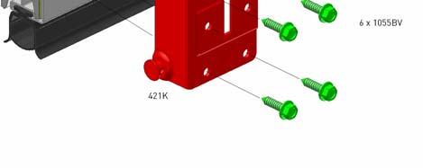
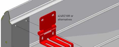
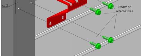
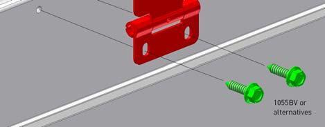
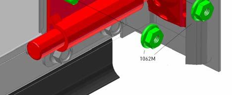
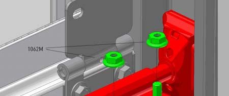
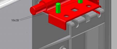
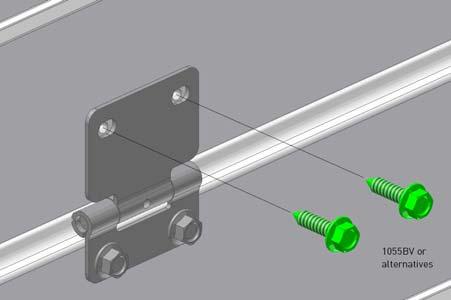
5 TOOLS FOR CORRECT AND RAPID ASSEMBLY (Battery) drill with Bit 4,0 mm Bit 4,5 mm Bit 6,5 mm Plug 10 mm Plug 13 mm Hexagonal key 4 mm Socket screw spanner 8mm (in) Ring /open ended spanner 10 mm Ring /open ended spanner 13 mm Ring /open ended spanner 15 mm Ring /open ended spanner 17 mm Socket wrench with ¼ square Wrench Gluing clamp Cord Water level (hose) 2 blocks of ca. 20 en 40mm in height Measuring equipment APPLIED FIXATION MATERIALS The applicable fixation material is described in the drawings of this manuals. Below an overview of the applied fasteners and optional alternatives. 1055BV, self-tapping screw Alternatives: 1055D, screw, 6,3x25mm, with drill-point Max torque 10Nm, key BV, screw 6,3x35mm 1053D, screw 6,3x35mm, with drill-point , , screw with socket hex cap, drill point 1054W-25, 1054W-35, screw with socket hex cap (RAL9010) Optional: 1055CAP10, white (RAL9010) cover for screws (key 10) 1070B35, bolt M8x B, press bolt 1062B, bolt M6x M, nut M8 1062M, nut M6 1062M, nut M6 Max. torque 13Nm, key 13 Max. torque 9,1Nm, key 10 Max. torque 5,3Nm, key BC, bolt M8x12, SuperClick secure bolt Max. torque 10Nm, key 13 NB! Fixation material for installing to wall and ceiling is not included in this manual! 5


6 RS200 SYSTEM OVERVIEW Shaft system with torsion springs, spring break devices drums, spring fittings, cables, etc. RS200H10etc. Horizontal double track set Connection horizontal tracks Door panels, sections With end caps, hinges, bottom brackets, bottom astragal and seal, top roller carriers, windows, etc. RSV10etc Vertical set with track, side seal and vertical angle RS200 : top view B = H 175mm for manual operated doors B = H 0mm for e-operated doors 6


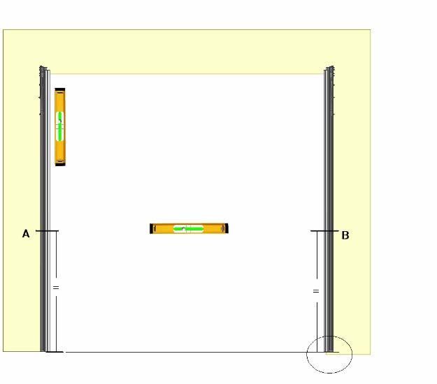
7 INSTALLING VERTICAL TRACK SYSTEM 7


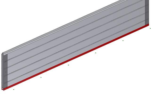
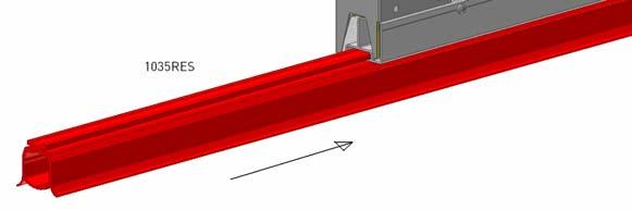
8 VERTICAL TRACK SET HORIZONTAL TRACK SET OPTIONAL: REINFORCEMENT HORIZONTAL TRACK SET For heavy doors, the horizontal track could be optionally reinforced with plate RX560R/L. 8


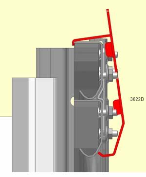
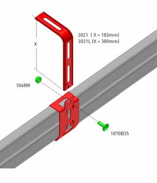
9 INSTALLATION WALL CONSOLES Traditional installation SuperClick installation 9


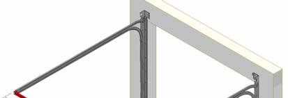
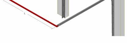

10 CONNECTION HORIZONTAL TRACKS (OPTIONAL) L = days opening width + 134mm SUSPENSION HORIZONTAL TRACK TO CEILING CLICK! 10


11 SHAFT SYSTEM INSTALLATION DOOR W<3000mm Cable drums No key-way: FF4X8, FF400-8(S), FF0402 Central shaft suspension Without key-way tube shaft Torsion springs with spring fittings and spring break devices CENTRAL SHAFT SUSPENSION (3 ALTERNATIVES) USA-MINI 312RM 312R 11
 Cable drums")

 Torsion springs with spring")


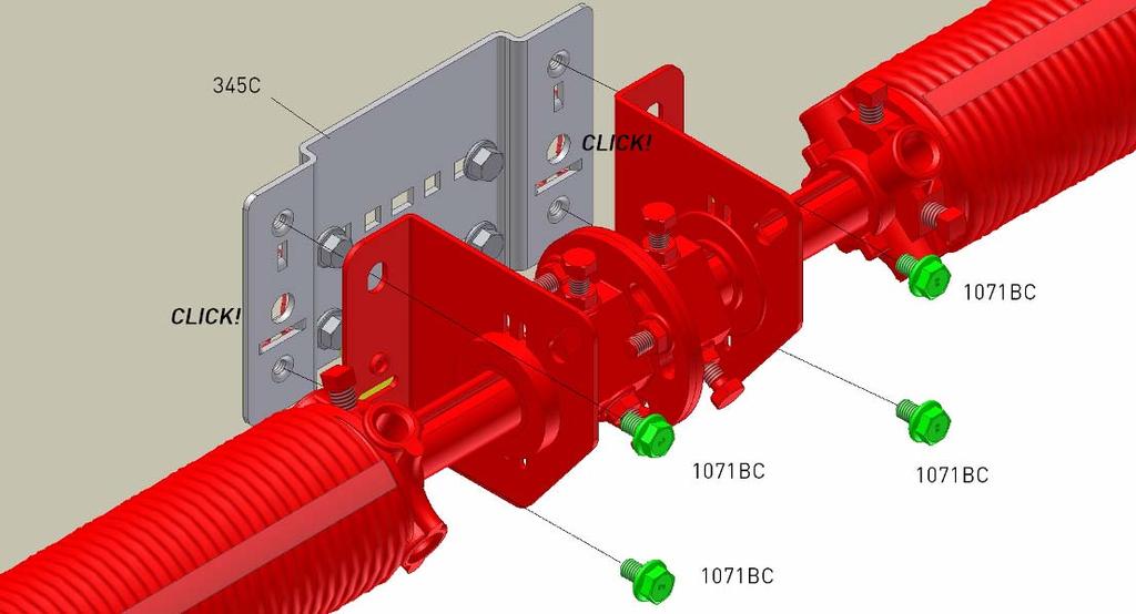
12 SHAFT SYSTEM INSTALLATION DOOR W>3000mm (double doors) Cable drums With key-way: FF-4-13, FF05NL12 etc. Central shaft suspension With coupler and 2 bearing plates (310CL/CR or USA-MINI) Torsion springs with spring fittings and spring break devices With key-way tube key-wayed shaft CENTRAL SHAFT SUSPENSION (W>3000mm) Traditional installation SuperClick installation Max 23 Nm 12


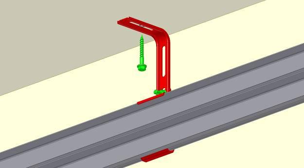
13 FIXATION TO THE LINTEL Traditional installation SuperClick installation 13


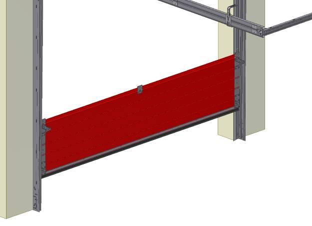


14 PANEL <> HARDWARE INSTALLATION 14

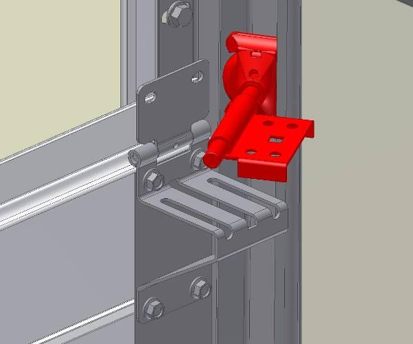


15 Alternative hinges: 411-series 15


 so that it can be")


16 INSTALLATION TOP PANEL / TOP ROLLER CARRIER Close the door and secure the door panel. Loosen the two self-tapping screws (1055BV) securing the top roller holder (417S) so that it can be displaced with a slight tick. Press the top panel against the side (upper) seal and slide the top roller holder as far as possible downwards and fix all screws. (minimum play between door panel and seal). The bearing roller lies snugly in the rounding of the bearing tracks. Alternative top roller carrier: adjustable 419S-series 16


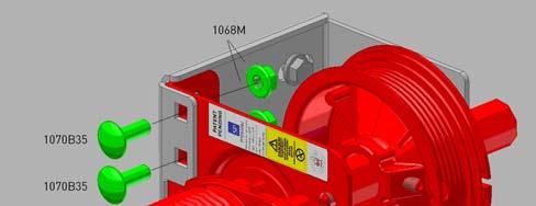
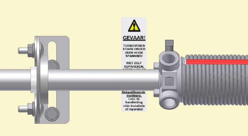
17 CABLES & TORSION SPRINGS! Cable running behind the rollers to the cable drums Without key-way: Fix shaft with clamp. Hook the cable connection in the drum. Rotate the drum for winding the cable. Position drum on the shaft. Max 10Nm 17


 4 panels 5 panels")

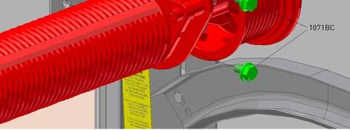
18 With key-way: manual GB rev.0 Feb-09 Max 23 Nm NB! See separate manual spring break device installation: 656Manual GB.pdf TORSION SPRING TENSIONING CAUTION! Torsion springs are subject to considerable tension! Proceed at all times with extreme caution. Installation, maintenance and repair should be carried out only by experienced and properly trained overhead door fitters. Use correctly fitting and properly maintained tension levers (FlexiForce code RES-TB). Number of turns on the torsion springs: Height (H) 4 panels 5 panels 2000mm 7.1 turns 6.8 turns 2125mm 7.6 turns 7.3 turns 2250mm 8.0 turns 7.7 turns 2375mm 8.4 turns 8.7 turns 2500mm 8.5 turns 9.2 turns 5 panels 6 panels 2750mm 9,4 turns 9,2 turns 3000mm 10,3 turns 10,0 turns Insert the 1 st tension lever completely into the slot. Turn the 1 st tension lever a quarter turn such that the spring is tensioned. 18


19 Insert the 2 nd lever completely into the next slot. Take over the tension of the spring from the 1 st tension lever to the 2 nd tension lever. Remove the 1 st tension lever from the slot. Turn the 1 st tension lever a quarter turn such the spring is tensioned. Repeat until number of turns is achieved. Then fix the spring plug to the shaft. Check the door balance and adjust the springs if necessary (equally both springs!) Max 25 Nm FINISHING THE DOOR 19

 closed conditions there are several")


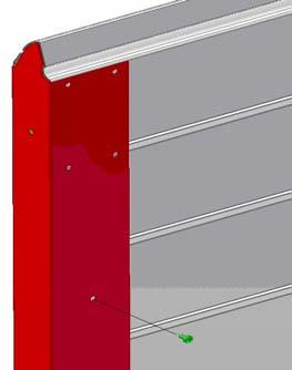
20 GREASING DOOR PARTS RE-ADJUSTING THE DOOR Open and close the door for checking all the settings. When the door panel is not hanging completely horizontally in the lifting cables in (almost) closed conditions there are several options for fine adjustment. A. Loosen the securing bolts of the cable drum and the drum relative to the tube shaft. B. When a coupling is employed this may be adjusted to ensure a better horizontal setting. Horizontal movement of the door can be limited (to max. 5mm) by installing 2065 distance rings on the roller shafts. 20


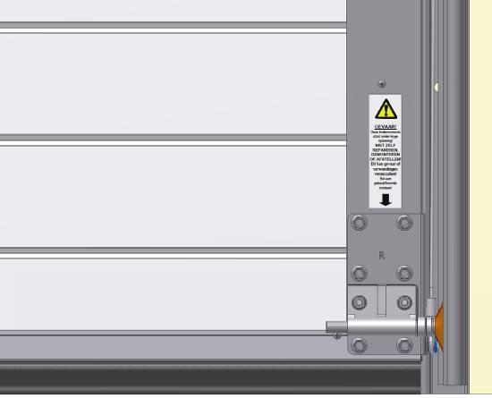
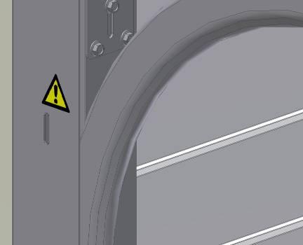
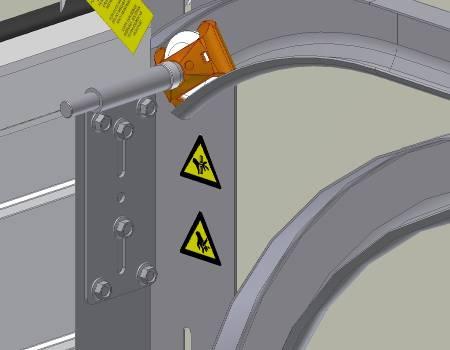
21 SAFETY LABELS ON THE DOOR A LABEL-GB etc. A 21
22 Install any additional accessories that you have ordered separately such as: Handgrip, lock, etc. See separate instructions in product packaging. NB! A lock may not be fitted to an electrically driven door. NB! A manually operated door should always be equipped with a hand grip, installed at a safe location on the door. NB! Do NOT INSTALL a pull rope with a power operated door at any time!! This can cause serious injuries or danger to the user of the door! Place your CE identification plate on the door (mandated!!) together with any warning labels required. Hand over necessary documents to the end-user: o User manual o Dismantling instructions (included in this manual) o Maintenance instructions (included in the user manual) o Service log book o Declaration of conformity IIa declaring the door is according to EN Visit for the most recent update of information on your obligations towards handing over a safe-to-use door. 22

. Keep in mind the max.")
23 OPTIONAL: E-OPERATION When you have selected an electrical operator drive (LIFTMASTER LM60K/R or other), then this should be assembled in conformity with the handbook supplied with this operator and above displayed instructions. You should clearly follow the instructions for electrical operation in this handbook. In order to maintain the closing peak force of the door within the CE-standards the attachment point of the drawbar should be fixed at the proper position. Ask your supplier for the correct position! NB! The person installing the door must check thoroughly if the combination between this door and the selected operator is safe to use (ITTR-approval report). Keep in mind the max. peak force that is allowed when closing the door. People could get hurt if the adjustment of the operator software, or the installation of the operator or the selected operator on this door, are not checked correctly!! 23

24 OPTIONAL: TANDEM ROLLERS 24


")


25 PANEL ASSEMBLY INSTALLING END CAPS POSITIONING OF END CAPS PER PANEL BRAND Kingspan panel Tecsedo panel Metecno panel 40ES500L/R, 40ES610L/R 40TS500L/R, 40TS610L/R 40FS500L/R, 40FS610L/R 40ES500WL/R, 40ES610WL/R (RAL9010) 40TS500WL/R, 40TS610WL/R 40FS500WL/R, 40FS610WL/R 40EM500L/R, 40EM610L/R 40TM500L/R, 40TM610L/R 40FM500L/R, 40FM610L/R 40EM500WL/R, 40EM610WL/R (RAL9010) 40TM500WL/R, 40TM610WL/R 40FM500WL/R, 40FM610WL/R 25


26 INSTALLING BOTTOM ALU + SEAL 26


27 CUTTING / FINISHING TOP PANEL NB! Make sure that the bottom panel will not be cut for adjusting the panel or door height. This should be done with the top section only! The attachment of the bottom bracket, which is holding the complete door weight, is relying on the construction of the panel. Danger can occur if the panel is cut at this point. Total door panel height = Days Opening Height (H) + 15mm 27
 - is the division of the weight equal on each panel, or are there panels with a different weight than the others, for")

28 TROUBLESHOOTING What should be checked if the door is not balanced properly? When a door is not well in balance, then it is necessary to check first the following details : 1. Is the given information correct : - weight of the door leaf (including hardware) - is the division of the weight equal on each panel, or are there panels with a different weight than the others, for instance by the application of different panels (glass, pass door with heavy profiles). 2. Are the correct parts supplied and fitted? especially the drums and springs are important : - are the correct dimensions supplied? 3. Is the door properly installed? - horizontal tracks really horizontally and not with inclination. 4. Were modifications made afterwards? - check if any changes were made during the fitting, or if a pass door was fitted later, or any reinforcement profiles fitted etc. 5. Is the e-operator installed and selected properly? - Is the installed e-operator suitable for this door? - Is the e-operator power adjusted properly for this door? (See installation manual operator) - Is the connection of the drawbar to the top-panel on the right position? (See attachment and manual operator). WHAT TO DO AFTER CABLE BREAK OR SPRING BREAK? NB! Also make sure to instruct the user about this. After spring breaking the door will be stopped by the 656-series spring break devices. The end user must contact immediately a qualified overhead door mechanic. The spring breaking device is a so called one-shot device. After it has acted, it must be replaced, together will all other possibly damaged components of the door, such as torsion springs, spring plugs, bearing plates etc. The door has to be inspected thouroughly. See separate manual 656 spring break device. After cable breaking, the door will be stopped by the second cable, which is designed to be strong enough to hold the weight of the door. Again, qualified overhead door mechanics must inspect the door and replace all possibly damaged components, such as: bottom brackets, cable, roller carriers, rollers, etc. SPRING IDENTIFICATION FlexiForce spring gauge: WGD10 28
29 DISMANTLING THE OVERHEAD DOOR ATTENTION! WARNING! To dismantle an existing overhead door, a number of precautions must be taken. For the safety of all concerned pay heed to the warnings and instructions given below! If in doubt, contact your supplier. Dismantling should only be carried out by experienced fitters. This manual is not suitable for d.i.y. purposes or for use by trainee fitters. This manual only describes the installation/dismantling of hardware for overhead doors and as such must be supplemented with instructions for any additional components. FOR ANY DETAILS ON THESE DISMANTLING INSTRUCTIONS, WE REFER TO THE INSTALLATION CHAPTERS OF THIS MANUAL WHERE DRAWINGS AND DETAILS ARE DISPLAYED. STEP 1. De-tensioning the torsion spring(s) CAUTION! Torsion springs and bottom brackets are under high tension. Exercise at all times great caution. Use properly fitting and maintained tension irons (see drawing). Start dismantling of the door by closing the door and securing its movement with a clamp on the vertical track. First the tension on the torsions springs and cable has to be released. Do this by following these instructions : 1 Insert the 1 st tensioning iron fully into the tensioning aperture. 2 Take over the tension of the spring with this tensioning iron. 3 Loosen the bolts in the tensioning plug and remove the key. 4 Turn the 1 st tensioning iron in the direction required. 5 Insert the 2 nd tensioning iron fully into the next tensioning aperture. 6 Take over the tensioning of the spring from the 1 st tensioning iron with the 2 nd tensioning iron. 7 Remove the 1 st tensioning iron from the aperture. 8 Turn the 2 nd tensioning iron a quarter turn in the direction required. 9 Insert the 1 st tensioning iron fully into the tensioning aperture. 10 Take over the tensioning of the spring from the 2nd tensioning iron with the1 st tensioning iron. 11 Repeat steps 4 through 10 until all tension is released. 12 Remove the last tensioning iron. STEP 2. Disconnect the electrical operator. Follow any instructions given in the separate manual of the operator. STEP 3. Loosen the cable drums and remove the keys. Act carefully, there might be some tension left on the cable. Check if the cable is slack. Remove the cable by disconnecting it from the bottom bracket and cable drum. STEP 4. Dismantle the horizontal track construction. STEP 5. Remove the panels one by one from the vertical track construction, starting with the top panel. Do this by loosening the hinges and rollers first. STEP 6. Remove the shaft construction from the lintel, after you have dismantled the E-operator from the shaft. If the shaft is divided and connected with a coupler, first disconnect the coupler and carefully remove both halves of the shaft system. Attention! Watch out for parts that might slide of the shaft, such as cable drums, bearings or keys. STEP 7. Remove vertical tracks and angles from the building construction. STEP 8. Make sure that you remove all the parts and panels in an environment kindly way. Check with your local authorities where and how you can leave this as garbage. 29
30 MAINTENANCE AND REPLACEMENT OF PARTS RESIDENTIAL DOORS An overhead door should be maintained and checked regularly to ensure safe operation and use. This is described in the EN-norms. GENERAL: 1 Torsion springs, brackets and other components which are attached to the springs and cables, are under extreem tension. If not handled properly, injuries or damages might occur! So, working on these components may only be carried out by qualified overhead door mechanics! 2 Replacement of broken or weared components should always be done by qualified overhead door mechanics. 3 When checking the door, always disconnect the electrical main power supply. Make sure that it is blocked against re-engaging without you knowing it. REGULAR MAINTENANCE: After installation: 1. Grease running part of the tracks MECHANIC 2. Grease the bearings of the rollers MECHANIC 3. Grease the shafts of the rollers MECHANIC 4. Grease the bearings of the shaft MECHANIC 5. Grease the hinge pins MECHANIC 6. Grease the lock MECHANIC 7. Protect the panels with carwax USER 8. Grease the rubbers slightly with vasaline USER After 3 months: 1. Complete inspection visualy MECHANIC 2. Check balancing system and adjust if needed MECHANIC 3. Grease all the above mentioned points if needed MECHANIC Every 6 months (or after every 750 cycles): 1. Check side seals on damage or wear and tear USER 2. Check top seal on damage or wear and tear USER 3. Check bottom seal on damage or wear and tear USER 4. Grease all above mentioned points USER 5. Clean the panels USER 6. Clean the windows (only water wash, do not use cloth) USER 7. Remove dirt and waste from the door or its surroundings USER Every 12 months (or after every 1500 cycles): 1. Check or test the fixation of the springs to the fittings MECHANIC 2. Check the balance of the door and adjust if needed MECHANIC 3. Check the cables for damage or wear and tear MECHANIC 4. Check the cable connection points on drums and bottom bracket MECHANIC 5. Check the roller on wear and free moving space MECHANIC 6. Check the hinges on breaking MECHANIC 30
31 7. Check the panels on damage, wear and roust MECHANIC 8. Check the spring breaking device acc. to instructions in manual MECHANIC 9. Check and test the safety edge system with operator MECHANIC 10. Check the manual operation of the door MECHANIC 11. Grease the springs MECHANIC After two years (or after every 3000 cycles): 1. Grease all the above mentioned points MECHANIC 2. Check or test the fixation of the springs to the fittings MECHANIC 2. Check the balance of the door and adjust if needed MECHANIC 3. Check the cables for damage or wear and tear MECHANIC 4. Check the cable connection points on drums and bottom bracket MECHANIC 5. Check the roller on wear and free moving space MECHANIC 6. Check the hinges on breaking MECHANIC 7. Check the panels on damage, wear and roust MECHANIC 8. Check the spring breaking device acc. to instructions in manual MECHANIC 9. Check and test the safety edge system with operator MECHANIC 10. Check the manual operation of the door MECHANIC 11. Grease the springs MECHANIC 12. Check side seals on damage or wear and tear MECHANIC 13. Check top seal on damage or wear and tear MECHANIC 14. Check bottom seal on damage or wear and tear MECHANIC ` 15. Check the shaft on wear and tear or damage MECHANIC 16. Check the bottom bracket on wear and tear and damage MECHANIC 17. Check the connection of the drum to the shaft (keys!) MECHANIC 18. Check and re-fix the bolt of the coupler MECHANIC 19. Check the connections of the track system MECHANIC 20. Check the suspension of the door to the lintel and ceiling MECHANIC Use for greasing Use for cleaning : PTFE or SAE20 or WD40 : Soft soap with water. Do not use aggressive soap or cloth. 31
Installation Manual SRR-70
 Installation Manual SRR-70 Contents 1. Symbols 3 2. General warnings 3 2.1 Safety requirements for assembly and first use 3 3. Terms and conditions 3 4. Area of application 3 5. Guidelines 4 6. Fixing
Northern Sales & Distribution Centre
 User Manual Industrial Door Northern Sales & Distribution Centre The Door Centre, Discovery Park, Crossley Road, Stockport, SK4 5BW /indupart /indupart /indupart /company/indupart-ltd Foreword This user
 www.thegaragedoorcentre.co.uk 0800 525 442 Handleiding montage / onderhoud / demontage Manual fitting / maintenance / dismantling Anleitung Montage / Wartung / Demontage Manuel montage / entretien / démontage
SPECIAL SAFETY WARNINGS OR REMARKS IN THIS MANUAL ARE INDICATED WITH THIS SYMBOL: READ THESE WARNINGS CAREFULLY.
 installation manual manual IND-HWS hardware set for industrial overhead doors max. w = 8,0m max. h = 6,0m max. kg = 700kg NL, VL, HL, LHR, FTR, FLH, FHL All rights reserved. Flexi-Force BV 2005 NEW! CE-LHR
Installation Manual Sectional door with rear springs (LF 70) Conform TÜV / CE EN
 Conform TÜV / CE EN") Installation Sectional door with rear springs (LF 70) Conform TÜV / CE EN 13241-1 UK Contents 1 Symbols and warning signs 3 2 General warnings 3 2.1 Safety requirements for assembly, first use and maintenance
Installation Sectional door with rear springs (LF 70) Conform TÜV / CE EN 13241-1 UK Contents 1 Symbols and warning signs 3 2 General warnings 3 2.1 Safety requirements for assembly, first use and maintenance
Instructions for Fitting, Operating and Maintenance Canopy Door RE / (St.: )
") EN Instructions for Fitting, Operating and Maintenance Canopy Door 1 818 012 RE / (St.: 12.2010) 12.2010 ENGLISH Contents 1 Safety Instructions... 3 1.1 Qualified persons... 3 1.2 Symbols and signal words
EN Instructions for Fitting, Operating and Maintenance Canopy Door 1 818 012 RE / (St.: 12.2010) 12.2010 ENGLISH Contents 1 Safety Instructions... 3 1.1 Qualified persons... 3 1.2 Symbols and signal words
SERIES A & AA ROLLER DOORS INSTALLATION GUIDE
 SERIES A & AA ROLLER DOORS INSTALLATION GUIDE THESE INSTRUCTIONS ARE PROVIDED FOR USE BY EXPERIENCED INSTALLERS OF GARAGE DOORS BY UNDER-TAKING THE INSTALLATION OF THIS DOOR, THE INSTALLER UNDERSTANDS
Instructions for Fitting, Operating and Maintenance
 EN Instructions for Fitting, Operating and Maintenance Retractable Door 1 818 024 RE / 10.2011 ENGLISH Contents 1 Safety Instructions... 3 1.1 Qualified persons... 3 1.2 Symbols and signal words used...
Relay Retrofit Program Cutting Tool Safety Guide
 Relay Retrofit Program Cutting Tool Safety Guide Copyright This document and parts thereof must not be reproduced or copied without written permission from ABB, and the contents thereof must not be imparted
Installation, Operating and Maintenance Instructions Retractable Door / Art.-Nr.:
 Installation, Operating and Maintenance Instructions Retractable Door 06.2008 / Art.-Nr.: 1 818 024 ENGLISH CONTENTS PAGE 1 SAFETY REQUIREMENTS 3 1.1 Symbols and key words used 3 1.2 Designated use 3 1.3
insulated sectional 2180mm (h) x 2550mm (w) Opening Size: 2140mm (h) x 2500mm (w) suits single car garage
 x 2550mm (w) Opening Size: 2140mm (h) x 2500mm (w) suits single car garage") insulated sectional Garage Door 2180mm (h) x 2550mm (w) Opening Size: 2140mm (h) x 2500mm (w) suits single car garage Disclaimer This product should be installed by a competent person or suitably qualified
insulated sectional Garage Door 2180mm (h) x 2550mm (w) Opening Size: 2140mm (h) x 2500mm (w) suits single car garage Disclaimer This product should be installed by a competent person or suitably qualified
Installation and Operation Manual
 1645 Lemonwood Dr. Santa Paula, CA 93060 USA Toll Free: 1 (800) 253-2363 Tel: 1 (805) 933-9970 rangerproducts.com Ranger Floor Jack Installation and Operation Manual Manual Revision B July 2017 Manual
Spring break device. Sep-10
 EN Spring break device Sep-10 Installation manual 1. Symbols and warning notices Danger Attention 2. General warning notices This installation manual is intended for suitably qualified staff and not for
Roof access hatch installation instructions
 Roof access hatch installation instructions 08.09.2017 Contents 1. Introduction 1 2. Safety precautions and warnings 1 3. Types of roof access hatches and product dimensions 2 4. Parts overview 3 5. Preparation
GARAGE DOOR OPENER OWNER S MANUAL S3/S4
 GARAGE DOOR OPENER OWNER S MANUAL S3/S4 Features! Locking door during power failure: If power failure occurs while the door is operating, the door can be released by pulling the clutch down, allowing
INSTALLATION INSTRUCTIONS
 INSTALLATION INSTRUCTIONS INSTALLATION INSTRUCTIONS THESE INSTRUCTIONS COVER THE INSTALLATION OF THE FOLLOWING REAR DOORS WITH OUTSIDE CABLES AND MAXIMUM SECURITY LOCK: 3/4" and 1" DryFreight TODCOLD Insulated
Plasma Dual Swing-Out (PDS Series) Wall Mount
 Wall Mount") INSTALLATION INSTRUCTIONS Plasma Dual Swing-Out ( Series) Wall Mount The wall mount is a rugged, versatile, and installer-friendly solution to unique display mounting requirements. In addition to providing
INSTALLATION INSTRUCTIONS Plasma Dual Swing-Out ( Series) Wall Mount The wall mount is a rugged, versatile, and installer-friendly solution to unique display mounting requirements. In addition to providing
Installation Instructions. Ultimate Screen. English Version 2.3
 Installation Instructions Ultimate Screen English Version 2.3 REMARKS. This manual simply describes the rules governing use and installing of the Ultimate Screen Blind. For different versions we would
CONVEYOR BELT. Mini-Maxi ,5 M 115 V
 CONVEYOR BELT Mini-Maxi 2006 4,5 M 115 V 1 CONTENTS 0. EC DECLARATION OF CONFORMITY PAGE 03 1. PURPOSE AND METHOD OF USE PAGE 04 2. AREA OF APPLICATION PAGE 04 3. ASSEMBLY OPTIONS PAGE 04 4. PUTTING INTO
AIR-SUSPENSION. Designed for: Alko Chassis
 AIR-SUSPENSION Dunlop Systems and Components Het Wegdam 22 7496 CA Hengevelde The Netherlands Tel.: +31-(0)547-333065 Fax: +31-(0)547-333068 Website: www.dunlopsystems.com Art. nr.: L.AL.02 Designed for:
Manual Industrial System Configurator
 Manual Industrial System Configurator V1 Start-up Selected your Language (currently only English) Navigation bar i: Click here for more information (if available) In this part you can see the configuration
Owners Manual Öhlins road & track front fork FG 43 Including:
 Owners Manual Öhlins road & track front fork FG 43 Including: Safety Adjusters Setting up your fork Changing springs Oil level adjustment Technical information Inspection & maintenance Service Tools 1
& OPERATING INSTRUCTIONS
 ELECTRIC WINCH 12 / 24 VOLT DC DW5000 (5000LBs/2272Kg) DW6000 (6500LBs/2727Kg) DW8000 (8000LBs/3663Kg) DW8500 (8500LBs/3863Kg) DW9000 (9000LBs/4091Kg) ASSEMBLY & OPERATING INSTRUCTIONS DW5000 Specification
GARAGE JACK MODEL NO: CTJ3000G PART NO: OPERATION & MAINTENANCE INSTRUCTIONS ORIGINAL INSTRUCTIONS
 GARAGE JACK MODEL NO: CTJ3000G PART NO: 7623030 OPERATION & MAINTENANCE INSTRUCTIONS ORIGINAL INSTRUCTIONS GC1217 INTRODUCTION Thank you for purchasing this CLARKE Garage Jack. Before attempting to use
JEEVES. JEEVES Installation Manual. Installation Manual The Easiest Do-It-Yourself Dumbwaiter on the Market
 1 888-323-8755 www.nwlifts.com JEEVES Installation Manual The Easiest Do-It-Yourself Dumbwaiter on the Market This manual will cover the installation procedure step-by-step. The installation of this dumbwaiter
Spring break device
 Spring break device 052010 IMPORTANT: Tensioned springs carry a high tension; always be very careful, especially when adjusting, and use tensioning rods (12025) of the right size and that are well maintained.
TABLE OF CONTENTS CHAPTER 1: SAFETY PRECAUTIONS. 2.3 COMPONENTS in the Hardwars Kit COMPONENTS on the Product SETP SETP2...
 TABLE OF CONTENTS CHAPTER : SAFETY PRECAUTIONS. SAFETY PRECAUTIONS... CHAPTER 2: INSTRUCTIONS 2. DIMENSIONS... 2.2 LIST OF PARTS... 2.3 COMPONENTS in the Hardwars Kit.... 2.4 COMPONENTS on the Product...
I. General Safety Precautions
 1 2 ATV/UTV WINCH Thank you for purchasing a. This manual covers operation and maintenance of the winch. All information in this publication is based on the latest production information available at the
SERIES B & C ROLLER DOORS INSTALLATION GUIDE
 SERIES B & C ROLLER DOORS INSTALLATION GUIDE THESE INSTRUCTIONS ARE PROVIDED FOR USE BY EXPERIENCED INSTALLERS OF GARAGE DOORS BY UNDERTAKING THE INSTALLATION OF THIS DOOR, THE INSTALLER UNDERSTANDS THE
Rollstar Shade Installation Instructions
 Rollstar Shade Installation Instructions All Lifting Systems Inside or Outside Mount Thank you for purchasing your new Rollstar shade. It has been custom-made from the highest quality materials to the
Installation Guide Section1
 Certification Test Report 908.42 MHz Low Power Communication Device Transceiver 372 MHz Discrete Receiver FCC ID: KJ8-0001715 IC: 3540A-0001715 FCC Rule Part: 15.249 IC Radio Standards Specification: RSS-210
Installation Manual DELT. Platform stairlift. Web: Tel: Mobile:
 Installation Manual DELT Platform stairlift Web: www.lehner-lifttechnik.at Tel: +4372783514 Email: office@lehnerlifttechnik.at Mobile: +436641612980 Table of content OBSERVE THE FOLLOWING POINTS BEFORE
INSTRUCTION MANUAL ANGLE GRINDER PT W
 INSTRUCTION MANUAL ANGLE GRINDER PT50360 4½ INCHES 120V 60Hz 600W 5A 12,000 rpm C US Note : Before operating this tool, read this manual and follow all safety rules and operating instructions. This electric
Drive Unit e-drive1. Installation instructions 04/2014. English translation of the original German installation instructions
 Drive Unit e-drive1 Installation instructions 04/2014 English translation of the original German installation instructions Contents Foreword... 3 Availability... 3 Structural features in the text... 3
Original. User Manual & Install Guide. Safe-T-Pull Inc. Page 1 of 15
 Original User Manual & Install Guide Safe-T-Pull Inc. Page 1 of 15 TABLE OF CONTINENTS 1. Before You Begin...3 Disclaimer...3 What Is Included...3 Claims...3 Contact Us...4 Safety Notes...4 2. Introduction...5
SI AT A22. English. Printed: Doc-Nr: PUB / / 000 / 01
 SI AT A22 English 1 Information about the documentation 1.1 About this documentation Read this documentation before initial operation or use. This is a prerequisite for safe, trouble-free handling and
Tooling Assistance Center
 Safeguards are designed into this application equipment to protect operators and maintenance personnel from most hazards during equipment operation. However, certain safety precautions must be taken by
Accessories for Wind Power Inverter WINDY BOY PROTECTION BOX 400 / 500 / 600
 Accessories for Wind Power Inverter WINDY BOY PROTECTION BOX 400 / 500 / 600 Installation Guide WBP-Box-IEN103320 IMEN-WBP-BOX Version 2.0 EN SMA Solar Technology AG Table of Contents Table of Contents
401B/1KDB CoolRite/FreezeRite Installation Manual I003
 401B/1KDB CoolRite/FreezeRite Installation Manual 99-16105-I003 Copyright 2011 by ALL rights reserved. Information in this document is subject to change without notice. Companies, names and data used in
Assembly instructions PRORUNNER mk1 2
 Assembly instructions PRORUNNER mk1 Version 0.1 / 01-JUN-2013 Copyright Qimarox B.V. All rights reserved. No part of this document may be copied, stored in a database and/or published by means of printing,
x 10 Belt Disc Sander
 Please dispose of packaging for the product in a responsible manner. It is suitable for recycling. Help to protect the environment, take the packaging to the local amenity tip and place into the appropriate
HOME-F Installation Manual
 HOME-F Installation Manual HOME-F Installation Manual ontents 1 Symbols...3 2 General warnings...3 2.1 Safety requirements for assembly and first use...3 3 Terms and conditions...3 4 Area of application...4
Medium Voltage Distribution FBX. Assembling a 1250A busbar Instructions.
 Medium Voltage Distribution FBX Assembling a 1250A busbar Instructions www.schneider-electric.com Contents Introduction... 3 Our Service Unit: our specialists, and suitably adapted services...... 3 Overview...
Sectional and Tilting Door Opener
 Sectional and Tilting Door Opener Installation Instructions and User Guide 600 800 1000 S/N WARNING Please read the manual carefully before installation and use. The installation of your new door opener
USE AND MAINTENANCE MANUAL
 LATERAL TURNOVER 360 ORIGINAL INSTRUCTIONS INTRODUCTION This manual includes instructions for assembly, maintenance (regular and extraordinary), and for possible faults with remedies. The instructions
PE51 HURLEY 3 STATION METAL SWING SET OWNER'S MANUAL
 PE51 HURLEY 3 STATION METAL SWING SET OWNER'S MANUAL WARNING! The disassembled product may contain small parts which pose a choking hazard to children under 3. IMPORTANT: This product may contain sharp
Product Information Overspeed governor GB 260
 Product Information GB 260 Copyright as per DIN ISO 16016. Manufactured under licence of C. Haushahn GmbH & Co. I Subject to modification. Published by SLC Sautter Lift Components GmbH & Co. KG Borsigstrasse
2 TONNE GARAGE JACK Model No: CTJ2QLP PART NO:
 TONNE GARAGE JACK Model No: CTJQLP PART NO: 7680 OPERATING & MAINTENANCE INSTRUCTIONS GC03 INTRODUCTION Thank you for purchasing this CLARKE Garage Jack. Before attempting to use this product, please read
NM-NP Pajero Rhino Heavy Duty - Two Bar Trackmount System
 NM-NP Pajero Rhino Heavy Duty - Two Bar Trackmount System Parts List Important: Please read these instructions carefully prior to installation. Please refer to your fitting instruction to ensure that the
Installation instructions
 Service Installation instructions Audi A3 (8V3) 2012 Roof bars 8V3.071.126 for vehicles with bright moulding package (PR no. 4ZB) and roof bars 8V3.071.126.L for vehicles with black moulding package (PR
S-Drive Performance Trainer
 S-Drive Performance Trainer SERVICE MANUAl Table of contents CHAPTER 1: Serial number location... 1 CHAPTER 2: Important Safety instructions 2.1 Read and Save These Instructions... 2 2.2 Before Getting
FTFR Maintenance and Parts Manual SQ-1 FLOOR TRUSS FINISH ROLLER. Operators Manual
 FTFR Maintenance and Parts Manual SQ-1 FLOOR TRUSS FINISH ROLLER Operators Manual FOREWORD This manual explains the proper maintenance of Square 1 Design Floor Truss Finish Roller as well as the daily
GENERAL SAFETY... 3 PARTS LIST...
 Rev 17a 1 GENERAL SAFETY... 3 PARTS LIST... 4 GTR100... 4 GTR058... 5 TECHNICAL SPECIFICATIONS... 6 FEATURES:... 6 QUICK INSTALLATION GUIDE... 7 GATE ARM INSTALLATION... 8 BEFORE YOU START... 8 INSTALLATION
SI AT A22. English. Printed: Doc-Nr: PUB / / 000 / 03
 SI AT A22 English 1 Information about the documentation 1.1 About this documentation Read this documentation before initial operation or use. This is a prerequisite for safe, trouble-free handling and
TSN (Cam-Over Wrench) Operating Instructions Rev 2.2 (4/13/2017)
 Operating Instructions Rev 2.2 (4/13/2017)") TSN Cam-Over Torque Wrenches The TSN is a preset torque wrench that's ideal for maintenance and production applications where over-torque conditions are not tolerated. The use of cam-over wrenches takes
TSN Cam-Over Torque Wrenches The TSN is a preset torque wrench that's ideal for maintenance and production applications where over-torque conditions are not tolerated. The use of cam-over wrenches takes
W BW GW. Workshop manual. Mechanical suspensions BPW, series ECO Cargo W / BW / GW. BPW-WH-W-BW-GW e
 W BW GW Workshop manual Mechanical suspensions BPW, series ECO Cargo W / BW / GW BPW-WH-W-BW-GW 35251401e Page 2 BPW-WH-W-BW-GW 35251401e BPW-WH-W-BW-GW 35251401e Page 3 Contents 1. Product identification...
Installation Instructions PowerBoard Automatic Retracting Running Board WARNING WARNING WARNING. Support
 Installation Instructions PowerBoard Automatic Retracting Running Board Vehicle Application: Jeep Wrangler 2-Door 2007-2016 Part Number 75651-15 Installation Tips Read and follow, precisely, all installation
INSTALLATION INSTRUCTION FOR: TORSION SPRING COUNTERBALANCE ASSEMBLY FOR RESIDENTIAL SECTIONAL DOORS
 410336-0001 8/10/04 INSTALLATION INSTRUCTION FOR: TORSION SPRING COUNTERBALANCE ASSEMBLY FOR RESIDENTIAL SECTIONAL DOORS Garage doors are large, heavy objects that move with the help of springs under high
I. Safety Requirement WARNING. ATV/UTV Winch
 1 2 ATV/UTV Winch Thank you for purchasing a COMEUP Winch. This manual covers operation and maintenance of the winch. All information in this publication is based on the latest production information available
GLACIER PRO RANGER MID SIZE MOUNT KIT
 GLACIER PRO RANGER MID SIZE MOUNT KIT P/N 2880261 APPLICATION FOR USE WITH THE GLACIER PRO MID SIZE PLOW SYSTEM (P/N 2880260) ON 2010 AND NEWER RANGER MID SIZE MODELS BEFORE YOU BEGIN Read these instructions
Auxiliary Air Suspension. Installation Manual L.HI.L4.C.M. Toyota Hilux 4 WD. May 2011
 Auxiliary Air Suspension Installation Manual Toyota Hilux 4 WD May 2011 CONTENTS 1. FOREWORD... 3 2. INTRODUCTION... 4 3. VERY IMPORTANT NOTES... 5 4. COMPLETE ASSEMBLY... 7 5. INSTRUCTIONS FOR INSTALLATION...
Lineman s Hoist. Operating, Maintenance & Parts Manual. Follow all instructions and warnings for LMST680-2
 Lineman s Hoist LMST0- Operating, Maintenance & Parts Manual Lineman s Hoist Follow all instructions and warnings for inspecting, maintaining and operating this hoist. The use of any hoist presents some
Austin. Aluminium Sectional Doors
 Austin Aluminium Sectional Doors The Austin aluminium sectional door has an elegant and timeless design ideal for contemporary style homes and commercial applications such as showrooms, workshops or small
Assembly instructions A B. A (mm) B (mm) C (mm) A A A A Walk-in Greenhouse
 B (mm) C (mm) A A A A Walk-in Greenhouse") ssembly instructions C MODEL (mm) (mm) C (mm) 907 34 90 950 689 4 9 3666 94 438 Walk-in Greenhouse Statement Dear Customer! May we congratulate you on your new Greenhouse. We feel sure that by following
ssembly instructions C MODEL (mm) (mm) C (mm) 907 34 90 950 689 4 9 3666 94 438 Walk-in Greenhouse Statement Dear Customer! May we congratulate you on your new Greenhouse. We feel sure that by following
Safety Shock Absorbers SCS33 to SCS64
 Safety Shock Absorbers SCS33 to SCS64 1 Operating Instruction SCS33-25EU SCS33-50EU SCS45-25EU SCS45-50EU SCS45-75EU Rod Button SCS64-50EU SCS64-100EU SCS64-150EU Integrated Rod Seals Main Bearing Content
INSTRUCTIONS FOR INSTRUCTIONS FOR USE USE Bambino panthera panthera
 INSTRUCTIONS FOR USE Bambino panthera Contents Intended use s 2 Adaptation s 3 Maintenance s 8 Safety s 9 Crash test s 11 Intended use The Panthera Bambino wheelchair is designed for children who need
Installation Manual. stairlift. A 4724 Neukirchen/W, Salling 8 Tel: 07278/ , Fax: 07278/ Mobil: 0664/
 Installation Manual Ω MEGA stairlift A 4724 Neukirchen/W, Salling 8 Tel: 07278/3514-15, Fax: 07278/3514-12 Email: office.lehner@gmx.at Mobil: 0664/1612980 CONTENTS OBSERVE THE FOLLOWING POINTS BEFORE INSTALLATION!...
Reflection. Aluminium Sectional Doors
 Reflection Aluminium Sectional Doors The Reflection aluminium sectional door features a chic round edge aluminium extrusion that can be clad with either glass or acrylic. Featuring a strong, sleek and
Acdc slimglide roller door operator
 Acdc slimglide roller door operator Owners manual ACDC SlideGlide ROLLER DOOR OPERATOR WARNING It is vital for the safety of persons to follow all instructions. Failure to comply with the installation
Pro. User Manual. Safe-T-Pull Inc Page 1 of 19
 Pro User Manual Safe-T-Pull Inc. 2015 Page 1 of 19 TABLE OF CONTINENTS 1. Before You Begin...3 Disclaimer...3 What Is Included...3 Unpacking Instructions....4 Claims...4 Contact Us...4 Safety Information...4
Sisu S-Cam Drum Brakes
 Sisu S-Cam Drum Brakes (For hub reduction rear axles since 1992) Maintenance Manual Sisu Axles, Inc. Autotehtaantie 1 P.O. Box 189 FIN-13101 Hämeenlinna Finland Phone int + 358 204 55 2999 Fax int + 358
GARAGE JACK MODEL NO: CTJ3000QLB PART NO: OPERATION & MAINTENANCE INSTRUCTIONS ORIGINAL INSTRUCTIONS
 GARAGE JACK MODEL NO: CTJ3000QLB PART NO: 7623205 OPERATION & MAINTENANCE INSTRUCTIONS ORIGINAL INSTRUCTIONS GC1216 2 INTRODUCTION Thank you for purchasing this CLARKE Garage Jack. Before attempting to
Operating manual & book of parts
 Operating manual & book of parts Ordering code: 08012014 Edition: 22-09-2014 (English) Mast Height Extension (MHE) www.telescopicforks.com MEIJER HANDLING SOLUTIONS 2006 2 Table of contents 1 Remarks...
Installation instructions
 Installation instructions Akrapovič Exhaust System Racing for the BMW G310R *505721* EN Revision 1.0 01/2017 www.akrapovic.com www.akrapovic.com Congratulations on purchasing the Akrapovič exhaust system.
PLOW MOUNT GLACIER PRO KIT
 PLOW MOUNT GLACIER PRO KIT P/N 2880262 APPLICATION FOR USE WITH THE GLACIER PRO MID-SIZE PLOW SYSTEM (P/N 2880260) ON 2015 AND NEWER RZR 00 MODELS BEFORE YOU BEGIN Read these instructions thoroughly and
Porte 150 Users Manual Swing Gate Opener 24V DC
 Porte 150 Users Manual Swing Gate Opener 24V DC for residential use only Signal Light Push-button Control Box 14 Contents 1. Important Safety Information 2. Product Description and Application 2.1 Application
SPEEDROLLER SERVICE MANUAL CE DECLARATIONS LOG BOOK USER MANUAL. Edition : May 2011
 SERVICE MANUAL CE DECLARATIONS LOG BOOK USER MANUAL SPEEDROLLER Edition : May 2011 1 8 2 3 4 Main components 1 drive 2 wind roller with hood (optional) 3 door panel 4 aluminium hinge profile 5 window section
ABACO MACHINES OPERATION MANUAL STONE/STEEL/GLASS/WOODS LIFTER (ASSGWL20) ABACO MACHINES (USA)
 ABACO MACHINES (USA)") ABACO MACHINES OPERATION MANUAL STONE/STEEL/GLASS/WOODS LIFTER (ASSGWL20) ABACO MACHINES (USA) 14508 S. Garfield Ave., Paramount, CA 90723, USA Tel : 310-532-0366 Fax : 310-532-99 Email : sales@abacomachines.com
ABACO MACHINES OPERATION MANUAL STONE/STEEL/GLASS/WOODS LIFTER (ASSGWL20) ABACO MACHINES (USA) 14508 S. Garfield Ave., Paramount, CA 90723, USA Tel : 310-532-0366 Fax : 310-532-99 Email : sales@abacomachines.com
L.IVE.LS.C.M (RWD Single Tire) Iveco Daily L and S (2005)
 Iveco Daily L and S (2005)") Auxiliary Air Suspension Installation Manual (RWD Single Tire) Iveco Daily L and S (2005) November 2018 CONTENTS 1. FOREWORD... 3 2. INTRODUCTION... 4 3. VERY IMPORTANT NOTES... 5 4. INSTRUCTIONS FOR INSTALLATION...
Auxiliary Air Suspension Installation Manual (RWD Single Tire) Iveco Daily L and S (2005) November 2018 CONTENTS 1. FOREWORD... 3 2. INTRODUCTION... 4 3. VERY IMPORTANT NOTES... 5 4. INSTRUCTIONS FOR INSTALLATION...
AUTO REWIND AIR HOSE REEL
 Model #s 46845, 46848 AUTO REWIND AIR HOSE REEL OPERATOR S MANUAL STORE THIS MANUAL IN A SAFE PLACE FOR FUTURE REFERENCE!? NEED HELP? Save time, contact us first. 888-648-8665 support@tekton.com WARNING:
Auxiliary Air Suspension. Installation Manual L.AL.02. AL-KO Chassis June 2009
 Auxiliary Air Suspension Installation Manual AL-KO Chassis 2002 2006 June 2009 CONTENTS 1. FOREWORD... 3 2. VERY IMPORTANT PREREQUISITES... 4 3. INTRODUCTION... 5 4. VERY IMPORTANT NOTES... 5 5. CONTENTS
User Manual Hoof trimmingcrush:sa0010. Version: User manual. Hoof trimming crush SA0010
 User Manual Hoof trimming crush SA0010 Manufacturer: Wopa Constructiebedrijf BV Rector Hulshofstraat 10 7135 JV Harreveld The Netherlands : +31-(0)544 372415 : +31-(0)544 372445 Email: info@wopa.com Website:
3/16 BC20001, Rev 6. Brakes. free-backing ASSEMBLY CALIBRATION OPERATION REPLACEMENT PARTS. Page 1
 3/16 BC20001, Rev 6 Brakes free-backing UNI-servo ASSEMBLY CALIBRATION OPERATION REPLACEMENT PARTS Page 1 WARRANTY POLICY, OPERATOR MANUALS & REGISTRATION Go online to www.demco-products.com to review
Sectional and Tilting Door Opener Installation Instructions and User Guide
 Sectional and Tilting Door Opener Installation Instructions and User Guide ET-600E ET-800E ET-1000E S/N WARNING Please read the manual carefully before installation and use. The installation of your new
GENUINE Interior Lighting Kit
 GENUINE Interior Lighting Kit INSTALLATION INSTRUCTIONS Thank you for purchasing a genuine Mazda accessory. Before removal and installation, be sure to thoroughly read these instructions. Please read the
Brakes. FREE BACKING # Right # Left. UNI-SERVO # Right # Left. Page 1. 1/15 BC20011, Rev 6
 1/15 BC20011, Rev 6 Brakes FREE BACKING #01971 - Right #01970 - Left UNI-SERVO #07911 - Right #07910 - Left ASSEMBLY CALIBRATION OPERATION REPLACEMENT PARTS Page 1 WARNING: To Prevent Serious Injury or
Maximum load carrying capacity: 100kg / 220lbs. Important Information. 1. Check Part No./Kit is correct 3. Fit roof rack accessory
 Important: Please read these instructions carefully prior to installation. Please refer to your fi tting instruction to ensure that the Backbone System is installed in the correct location. Check the contents
HD Hinge Casting HARDWARE: CONTENTS:
 Page 1/9 Part #11546.51 CONTENTS: HD Hinge Casting Spacer Plates (2 PCS) HD Hinge Casting HARDWARE: Hex Bolt X 4 Washer X 4 TOOLS REQUIRED: Socket Wrench 10 extension 13mm socket 3/4 deep socket T-20,
GARAGE DOOR OPERATOR USER S MANUAL
 GARAGE DOOR OPERATOR USER S MANUAL - DOMESTIC USE CIL-CD800S Chain) CIL-BD800S Belt GARAGE DOOR OPENER OWNER S MANUAL - DOMESTIC USE CIL-CD800S CD800S(Chain Chain) CIL-BD800S BD800S(Belt Belt) 1 Features
Fransgård. Manual GB V-4000 V Farm tractor winch
 Fransgård Manual GB Farm tractor winch V-4000 V-6500 Fransgård Maskinfabrik A/S Fredbjergvej 132 DK - 9640 Farsø Telefon : +45 98 63 21 22 Fax : +45 98 63 18 65 Web : www.fransgard.dk E-mail : info@fransgard.dk
KeContact P20. User manual
 KeContact P20 User manual Comments to this manual In this manual you will find warnings against possible dangerous situations. The used symbols apply to the following meanings:!! WARNING! Indicates a potentially
3-TONNE GARAGE JACK OPERATION & MAINTENANCE INSTRUCTIONS MODEL NO: CTJ3000GB PART NO: ORIGINAL INSTRUCTIONS
 3-TONNE GARAGE JACK MODEL NO: CTJ3000GB PART NO: 7623032 OPERATION & MAINTENANCE INSTRUCTIONS ORIGINAL INSTRUCTIONS GC1216 2 INTRODUCTION Thank you for purchasing this CLARKE Garage Jack. Before attempting
Armon Edero. User manual
 User manual Armon Edero Foreword.... 2 Symbols used 2 Intended use.... 2 About the Armon Edero... 2 Mounting options of the Edero 2 Braces. 3 How to set up the Armon Edero.. 3 How to attach the brace to
Roller Door Operator
 INSTALLATION INSTRUCTIONS AND OWNERS MANUAL Roller Door Operator IMPORTANT PLEASE READ THESE INSTRUCTIONS CAREFULLY PRIOR TO COMMENCING THE INSTALLATION OF THE OPERATOR UNIT CAUTION This Automatic Opener
INSTALLATION INSTRUCTIONS
 REV 3 05/13/2016 INSTALLATION INSTRUCTIONS PART NO. 702001T PRODUCT DESCRIPTION: FRONT INNER FENDER LINER APPLICATION: JEEP WRANGLER / WRANGLER UNLIMITED PRODUCT SAFETY & LEGAL DISCLAIMER IMPORTANT READ
OPERATIONAL ADVICE WARNING: TO PREVENT SERIOUS INJURY, PLEASE READ AND UNDERSTAND ALL WARNINGS AND INSTRUCTIONS BEFORE USE.
 OPERATIONAL ADVICE WARNING: TO PREVENT SERIOUS INJURY, PLEASE READ AND UNDERSTAND ALL WARNINGS AND INSTRUCTIONS BEFORE USE. SAVE THIS MANUAL Keep this manual in a safe place for future reference. This
Timber Sectional Doors
 are available in a wide variety of sophisticated panel designs and finishes and provide a warm, cozy and welcoming impression. Typically manufactured from Western Red Cedar, these quality doors can truly
RMK HANDLEBAR KIT P/N ; ; APPLICATION BEFORE YOU BEGIN KIT CONTENTS. Verify accessory fitment at Polaris.com.
 RMK HANDLEBAR KIT P/N 2883835; 2883836; 2883837 APPLICATION Verify accessory fitment at Polaris.com. BEFORE YOU BEGIN Read these instructions and check to be sure all parts and tools are accounted for.
INSTALLATION INSTRUCTIONS
 REV 3 05/13/2016 INSTALLATION INSTRUCTIONS PART NO. 702002T PRODUCT DESCRIPTION: REAR INNER FENDER LINER APPLICATION: JEEP WRANGLER / WRANGLER UNLIMITED PRODUCT SAFETY & LEGAL DISCLAIMER IMPORTANT READ
Installation manual portable distributors
 EN Installation manual portable distributors EN 60003206 Issue 11.2016 15/11/2016 Table of contents 1 About this manual 3 1.1 Structure of the warnings 3 1.2 Symbols used 4 1.3 Signal words used 4 2 Intended