INSTRUCTION MANUAL- PLANT OPERATIONS
|
|
|
- Delilah Nelson
- 5 years ago
- Views:
Transcription


1 INSTRUCTION MANUAL- PLANT OPERATIONS NMB SPLICE SLEEVE SYSTEM- REINFORCING BAR CONNECTOR REVISED W 6 Mile Road, Suite 205 Livonia, MI April 2014

2 OVERVIEW 1 P a g e

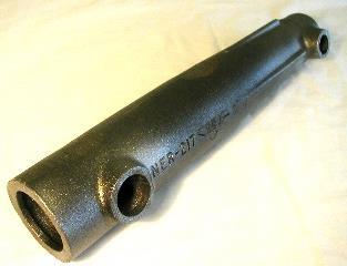
3 NMB Splice Sleeve System with Accessories 2 P a g e
 inch O.D. (C ) inch Max. Dia. (B) inch I.D. (A) inch Wide End Diameter Total Tolerance inch O.D. (A ) inch Factory Dowel (E1) inch Field Dowel (E2) inch Min. Max. Min. Avg. Max. SS Mortar lbs.")
4 Dimension Details of NMB Splice Sleeve DIMENSIONS OF NMB SPLICE-SLEEVES RECOMMENDED REBAR EMBEDMENT LENGTH Sleeve No. Bar Diameter ASTM Bar Size U.S. Metric Sleeve Length (L) inch Narrow End Diameter I.D. (C) inch O.D. (C ) inch Max. Dia. (B) inch I.D. (A) inch Wide End Diameter Total Tolerance inch O.D. (A ) inch Factory Dowel (E1) inch Field Dowel (E2) inch Min. Max. Min. Avg. Max. SS Mortar lbs. per Sleeve (kg) 5U-X #5 16 MM 9.65 (245) 0.87 (22) 1.50 (38) 1.89 (48) 1.26 (32) 0.63 (16) 1.89 (48) 4.13 (105) 4.33 (110) 4.13 (105) 4.53 (115) 4.92 (125) 1.26 (0.57) 6U-X #6 20 MM (285) 1.02 (26) 1.65 (42) 2.05 (52) 1.42 (36) 0.67 (17) 2.05 (52) 4.92 (125) 5.12 (130) 4.92 (125) 5.32 (135) 5.71 (145) 1.76 (0.80) 7U-X #7 22 MM (325) 1.14 (29) 1.77 (45) 2.36 (60) 1.73 (44) 0.86 (22) 2.36 (60) 5.71 (145) 5.91 (150) 5.71 (145) 6.11 (155) 6.50 (165) 2.65 (1.20) 8U-X #8 25 MM (370) 1.30 (33) 1.93 (49) 2.52 (64) 1.89 (48) 0.89 (23) 2.52 (64) 6.50 (165) 6.69 (170) 6.50 (165) 6.99 (178) 7.48 (190) 3.46 (1.57) 9U-X #9 28 MM (415) 1.42 (36) 2.06 (52) 2.67 (68) 2.01 (51) 0.89 (23) 2.67 (68) 7.40 (188) 7.56 (192) 7.40 (188) 7.88 (200) 8.35 (212) 3.95 (1.79) 10U-X #10 32 MM (455) 1.57 (40) 2.28 (58) 2.87 (73) 2.16 (55) 0.89 (23) 2.87 (73) 8.19 (208) 8.35 (212) 8.19 (208) 8.66 (220) 9.13 (232) 4.94 (2.24) 11U-X #11 35 MM (495) 1.73 (44) 2.40 (61) 3.03 (77) 2.32 (59) 0.91 (23) 3.03 (77) 8.98 (228) 9.13 (232) 8.98 (228) 9.45 (240) 9.92 (252) 6.02 (2.73) SNX #11 35 MM (485) 1.69 (43) 3.03 (77) 3.03 (77) 2.32 (59) 0.91 (23) 3.03 (77) 8.86 (225) 9.25 (235) 8.27 (210) 8.86 (225) 9.45 (240) 5.71 (2.59) A11W #11 35 MM (495) 1.73 (44) 3.31 (84) 3.30 (84) 2.60 (66) 1.19 (30) 3.30 (84) 8.86 (225) 9.69 (246) 8.27 (210) 8.96 (228) 9.50 (241) 6.99 (3.17) 14U-X #14 40 MM (620) 2.01 (51) 2.80 (71) 3.46 (88) 2.60 (66) 0.91 (23) 3.46 (88) (290) (295) (290) (303) (315) 9.19 (4.17) 18U #18 57 MM (920) 2.68 (68) 3.66 (93) 4.25 (108) 3.27 (83) 1.01 (26) 4.25 (108) (432) (460) (432) (446) (460) (11.48) B 3 P a g e
 in diameter on the mold for installing PIN Type Sleeve Setters (PS model). See Page III-12 and Page III-14 for installation instructions of STR-CT and PS, respectively.")

5 PREPARATION OF FORMWORK a. Drill holes of 5/8 inch (16 mm) in diameter on the mold for installing CAM Type Sleeve Setters (STR-CT model). b. Drill holes of 3/4 inch (19 mm) in diameter on the mold for installing PIN Type Sleeve Setters (PS model). See Page III-12 and Page III-14 for installation instructions of STR-CT and PS, respectively. Also drill holes of the appropriate diameter at the opposite side of the molds for the protruding bars. See Page III-14 for suggested ways of securing reinforcing bars. Figure III-1: Section of Precast Member before Pouring Concrete PREPARATION OF REINFORCING BARS- DETERMINING THE LENGTH Figure III-2: Determination of Reinforcing Bar Length Protruding Bar Length (B): B = A + L 1 + L 2 + x Required Length of Reinforcing Bar (C): C = L E + A + B + y A, A : Embedment Bar Length L2 : Design Depth of Joint Gap L1 : Design Depth of Floor Slab L : Design Height of Precast Unit E : Sleeve length. x : Design Tolerance (See Page I-9 Table I-1, E-2 Average) y : Cutting Error NOTE: It is essential that the reinforcing bars be cut accurately to the specified tolerance. It is necessary to set a bar stop on the bar cutting machine and to make sure the bar is held tightly against the stop before cutting. The bar fabricator should be cautioned that tolerances used for cutting bars for use in cast-in- place concrete are not acceptable for use with this type of connection. Cutting tolerance should be limited to not more than ±1/8 inch for a total of 1/4 inch. Short bars should not be accepted. 4 P a g e
6 ASSEMBLY OF NMB SPLICE-SLEEVES Molded End Cap Rubber Plugs (RB) are used for sleeve sizes #5 through #14 while Polyethylene Plugs (PP) along with plastic tape are used for #18 sleeves. Screw-in Elastomer Plugs (EP) are used for SNX11 and A11W. The step-by-step installation procedure of Rubber Plugs (RP) is described below (Figure III-3). For installing the Polyethylene Plugs (PP), refer to Page III-17. INSTALLATION OF END RUBBER CAPS ON SLEEVES Step 1: Firmly hold the sleeve in an upright position and slip the side hole of the End Cap over the grout outlet projection of the sleeve. Hold it in place with thumb just above grout port. Step 2: Pull the End Cap slant-ways over the narrow end of the sleeve. Step 3: Pull the cap downwards to cover the end of the sleeve. Step 4: Stretch the cap down firmly so that the plug fits evenly around the entire end of the sleeve and covers the raised ring in the sleeve. Figure III-3: Installation of Rubber Cap at Narrow End of Sleeves (For Model U-X) 5 P a g e
7 GROUT INLET AND OUTLET TUBES In the Post-Grout (PG) System, SS Mortar grout will be pumped into the sleeves through the grout inlet tube until it comes out of the outlet tube. The grout ports are sized to receive tubes made from metric PVC pipe for Model U-X while US sizes of ½ and ¾ in. for A11W and SNX11. The metric PVC pipes are available from Splice Sleeve North America. British Standard metric PVC sizes will not fit the grout ports. The use of an adaptor may be considered in order to permit the use of American standard ASTM Schedule 40 PVC pipe sizes. Tubing sizes are as follows: Port Location For Model U-X For A11W & SNX11 Inlet Port mm /4 in. Outlet Port mm /2 in. In normal practice, rigid straight PVC pipe is recommended for both inlet and outlet tubes. However, in special applications, flexible grout tubes can also be used. Care must be taken to ensure that the flexible tubes do not have any kink or damaged during casting. The user is cautioned that such tubing will be difficult to clear in an event of obstruction caused in the tubing. When flexible tubing is used, special care must be taken to tie and seal the tubes securely into the sleeves. The other end of the tubing also needs to be secured to the form unless it is required to protrude from the top of the form. When rigid tubing is used, the lengths of the grout tubes will depend upon the required applications. Refer to Figure III-4. Figure III-4: Different Modes of Sleeve Position and Corresponding PVC Tube Installation FOR POSITIONS A & C: TUBE ENDS AT FORM SURFACE The ends of the grout tubes should be made flush with the mold. Hole Seals (HS) should be used in all cases. In some cases, where it is desired to offset the tubing from the face of the formed concrete for cosmetic or other reasons, a rubber stopper can be used instead of the Hole Seal (HS). In this case, the size of the rubber stopper should be such that when it is inserted half-way into the grout tube, a tight seal is assured. FOR POSITION B: TUBE ENDS ADJACENT TO THE FINISHED CONCRETE SURFACE When the tubes are installed in a position with the end oriented to the finished concrete, care must be taken to secure the tubes in a fixed position, and the sleeves should be supported with chairs to ensure that the tube ends will not be lost below the concrete surface during casting. Grout tubes may be depressed slightly below the finished concrete surface so that finishing operations can pass over the tubes. In this case, fill the Hole Seals (HS) with grease or oil-based glaziers putty so that they can be located later. In some applications, where a smooth finish is not required, the tubes can be extended above the finished concrete surface. Hole Seals should still be used to cap the ends of the tubes. 6 P a g e
8 INSTALLATION OF INLET AND OUTLET TUBES The grout tubes must be firm and tight in order to prevent intrusion of cement paste during casting operations. Tubes should be tied off firmly to rebars, sleeves, etc., so as not to be disturbed nor displaced during concrete placement. 1. The tubes should be located so as to minimize the length. The outlet locations should be carefully chosen to make sure that the tubes will be easily accessible during the installation of precast concrete members. 2. There are two commonly used methods of securing the grout tubes to the sleeve ports: c. The end of the tube is wrapped with electrician s tape. The wrap extends about 1/6 inch (4.3 mm) over the end of the tube. The tube is then placed inside the grout port until it is fully inserted. Usually, a wooden mallet or other means is used to avoid shattering of the plastic pipe. The tube should be tested for security by manually trying to pull it out. If it can be pulled out by hand, an additional wrap of tape is used and the process is repeated. This method permits immediate installation of the sleeve assembly and placing of concrete without delay. However, this method will not work well with flexible tubing. d. The end of the rigid or flexible tubing is coated with a type of cement paste recommended by the tubing manufacturer. The tube is then fully inserted into the sleeve port and the cement is allowed to set. The required time period necessary to avoid dislodgement of tube by hand varies with ambient temperature. 3. When using flexible grout tubes, it is recommended that the tubes must be secured firmly using tie wire at each end. It must be securely fasten both at the sleeve ends and at the grouting ends to avoid coming out during casting process. 4. As a general rule, the grout tubes should be located at right angles to the molds, or to the concrete surfaces. In some cases, as shown in Page III-10, this may not be possible. The tubes may be cut on a bevel parallel to the form face. If the bevel cut is elected, the Hole Seals provided cannot be inserted. The use of tightfitting backer rod can be used instead along with tape to seal the tubes. Figure III-5: Installation of Inlet and Outlet Tubes (Model U-X) 7 P a g e
9 REMARKS: Plastic or electrical tape may be used with, or instead of, cement to secure the grout tubes in the sleeve grout ports. If the PVC pipe fitting is too loose in the grout port, one or more wraps of tape can be used to tighten the fit. As indicated below, plastic tape may be used instead of cement. Normally only a single wrap of tape is sufficient. Figure III-6 shows the wrapping of electrical tape for installation of PVC pipes in the grout ports. Adhesive may also be applied on the tape for better bonding. Fit the tube firmly into the hole. Figure III-6: Wrapping of Electrical Tape around PVC Pipes SEALING THE END OF THE GROUT TUBES After setting the grout tubes, the ends should be sealed with Hole Seals (HS) so as to prevent intrusion of concrete or mortar into the tubes during placement of concrete. Glazier's putty (oil based) or heavy grease should be used to fill the recess of the Hole Seal. This will facilitate in locating the grout tube ends later when the oil bleeds through the concrete. 8 P a g e
10 Figure III-7: Glazier s Putty for Locating Tubes after Casting HOW TO DETERMINE THE LENGTH OF PVC TUBES Size for Model U-X: Grout inlet tubes: I.D. 0.87" (22 mm) O.D. 1.02" (26 mm) Grout outlet tubes: I.D. 0.55" (l4 mm) O.D. 0.71" (l8 mm) Size for Model A11W & SNX11: Grout inlet tubes: I.D. 0.62" (16 mm) O.D. 0.84" (21 mm) - PVC Schedule 40 ½ in. Grout outlet tubes: I.D. 0.82" (21 mm) O.D. 1.05" (27 mm) - PVC Schedule 40 ¾ in. The length of the PVC tubes (L 1 and L 2) shall be calculated as mentioned below: Outlet Port: L 1 = A B 1 Inlet Port: L 2 = A B 2 where, A : The length from the concrete surface to the center of the sleeve. B 1 : The distance from the center of the sleeve to where the outlet port PVC tubes are attached. B 2 : The distance from the center of the sleeve to where the inlet port PVC tubes are attached. 9 P a g e

11 Table III-1: Distance B 1 and B 2 of Sleeves Sleeve Size Bar Size U.S. Bar Size Metric 5U-X #5 16 MM 6U-X #6 20 MM 7U-X #7 22 MM 8U-X #8 25 MM 9U-X #9 28 MM 10U-X #10 32 MM 11U-X #11 35 MM SNX-11 #11 35 MM A11W #11 35 MM 14U-X #14 40 MM 18U #18 57 MM B 1, Inch 0.79 (20) 0.87 (22) 1.02 (26) 1.10 (28) 1.18 (30) 1.26 (32) 1.38 (35) 1.52 (39) 1.65 (42) 1.57 (40) 1.84 (47) B 2, Inch 0.79 (20) 0.87 (22) 1.02 (26) 1.10 (28) 1.18 (30) 1.26 (32) 1.38 (35) 1.52 (39) 1.65 (42) 1.57 (40) 2.16 (55) Note: Except 18U, B 1 and B 2 are the same at each U-X Sleeve EXAMPLES OF GROUT TUBE INSTALLATIONS (PLAN VIEWS) Figure III-8: Details of Dimensions B 1 and B 2 A. SQUARE & RECTANGULAR COLUMNS: Grouting can be done from any face. Figure III-9: PVC Tube Installation when All Sides are Accessible B. SPECIAL SITUATIONS: Where grouting access is restricted, such as for architectural panels, or when certain faces are inaccessible or hidden. Figure III-10: PVC Tube Installation when All Sides are NOT Accessible 10 P a g e


12 Example of PVC Installation 11 P a g e

13 Under circumstances where the ends of the grout tubes are not to be located at right angles to the form, they may be extended through holes in the forms. Because the tubes are on an angle, keep them short and make certain that the holes in the forms large enough to permit removal of the forms over the ends of tubes. If it necessary for the tubes to be flush to the forms, foam plastic or rubber stoppers may be used to seal the tubes. It is important to securely tie the tubes so that they will not be lost. Grout tubes have also been heated and bent in electrician furnaces in order to provide clearance for the tubes and to permit the ends of the tubes to meet the form face at a right angle. The user is cautioned that bent tubes may be difficult to clear in an event they become plugged. able are the CAM-TYPE SLEEVE SETTER (STR-CT): DETAILS Figure III-11: Special Condition of PVC Installation Figure III-12: Details of CAM Type Sleeve Setter It is important to use a rod that fits the socket else flaring of the hole will occur resulting in reduced life of tool. The hole size is 13 mm or about 1/2 inch. 12 P a g e
 F: Thickness of SW (Setter Washer) G: Height of Nut H: Inside Diameter of Socket J: Outside Diameter of Setter Shaft L: Overall Length of")
... 1-5/32 (30) 6/32 (4.5) 9/16 (15) 1/2 (13) 5/8 (16) 7-1/16 (180) 8,9,10,11,14, & 18 1-1/4 (32) 1-3/4 (45) 1.00 (25)... 1-3/4 (45) 6/32 (4.")
14 Figure III-13: Dimension Details of CAM Type Sleeve Setter A: Distance between Socket end and the shaft end B: Distance between the Cam-top and the shaft end C: Height of bushing D: Thickness of casting forms to be used E: Height of SR (Setter Rubber) F: Thickness of SW (Setter Washer) G: Height of Nut H: Inside Diameter of Socket J: Outside Diameter of Setter Shaft L: Overall Length of Setter Shaft Table III-2: Dimensions of Sleeve Setter CAM Type (STR-CT) STR-CT # A, inch B, inch C, inch D, inch E, inch F, inch G, inch H, inch J, inch L, inch 5,6,& 7 1-1/4 (32) 1-3/4 (45) 1.00 (25) /32 (30) 6/32 (4.5) 9/16 (15) 1/2 (13) 5/8 (16) 7-1/16 (180) 8,9,10,11,14, & /4 (32) 1-3/4 (45) 1.00 (25) /4 (45) 6/32 (4.5) 9/16 (15) 1/2 (13) 5/8 (16) 7-1/16 (180) 13 P a g e
15 INSTALLATION OF SLEEVES WITH CAM-TYPE SLEEVE SETTER (STR-CT) Procedure of installation of sleeves with CAM type sleeve setter: 1. Remove the Quick-pin from the shaft along with the cam and bushing. 2. Install the setter rubber, washer and nut on the shaft and insert the assembly through the hole in the mold from the inside of the form. 3. Place the bushing over the end of the shaft, and reassemble the cam to the shaft with the pin. Rotate the cam so that the cam shaft is parallel to outside face of the mold. 4. Tighten the nut with a wrench until the side edge of the cam, when parallel to the outer head of the bushing, is approximately 1/8 (3 mm) ~ 7/32" (5 mm) from the outer head of the bushing. Do not move the nut once it is set in position. 5. Place the wide end of the sleeve over the setter rubber until it contacts the side of the mold. Insert a lever rod into the socket of the cam shaft, and rotate the cam so that the cam shaft is perpendicular to the face of the mold. Test for proper fit by attempting to twist sleeve. If loose, go back to step 4 and tighten nut. 6. Insert the rebar until it contacts the Rebar Stop in the Sleeve, and secure the rebar in position. Figure III-14: Installation of CAM Type Sleeve Setter at Precast Plant Note: In order to strip the precast element from the mold, the shaft/rubber can be pushed into the sleeve and retrieved later. 14 P a g e


16 PIN TYPE SLEEVE SETTER: DETAILS The second option for setting NMB Splice Sleeves in the mold is the Pin Setter. The Pin Setter uses three setter pins to extend up inside of the shell of NMB Splice Sleeves, grasping the rim or lip at the opening and holding the sleeve with a tight metal-to-metal connection. The Pin Setter is characterized by easy and fast installation, high durability and cost-saving option (just replace rubber ring and washer when worn out). Pin Setter s metal head and pins can keep NMB Splice Sleeve tight and straight to the mold with no drooping. The Pin Setter is currently available in two size ranges: PS0810 to be used for sleeve sizes 8, 9, and 10. PS1114 to be used for sleeve sizes 11 and 14. The size should be specified along with the component when ordering e.g. PS0810. Characteristics of Pin Setters: 1. Ease and fast installation 2. Hard and durable. The only nonmetal items are the inexpensive Rubber Ring and Rubber Washer. 3. Pin Setter s metal head and pins keep the sleeves firm and straight to the molds-even better than the existing Cam-Lock with Rubber Sleeve Setters. 4. Two pin setters to replace five Cam-Lock Sleeve Setters saving money and space. The different components of Pin Setter are shown in the Figure III-15 below: Rubber Ring (PRR) Rubber Washer (PRW) Steel Washer Hex Nut Head Shaft Pins (PSP) Pin Setter Assembly Figure III-15: Details of PIN Type Sleeve Setter 15 P a g e
 1-1/4 (32) 2-3/8 (60) 3-3/8 (85) 4-1/2 (115) PS1114 2-1/16 (53) 1-1/2 (37.")
17 Table III-3: Dimension of Sleeve Setter Pin Setter Type Pin Setter Head Diameter, inch Head Height, inch Length of Hex Nut, inch Length of Shaft, Inch Overall Length of Pin Setter, inch PS /8 (42) 1-1/4 (32) 2-3/8 (60) 3-3/8 (85) 4-1/2 (115) PS /16 (53) 1-1/2 (37.5) 2-3/8 (60) 3-3/8 (85) 4-1/2 (115) INSTALLATION OF NMB SLEEVES WITH PIN SETTER Procedure for installation of sleeves with Pin Setter: Step 1: Install Pin Setter to the mold 1. Drill a ¾ hole on the mold for installing Pin Setter 2. Loosen a hex nut and take out the steel washer 3. Insert the Pin Setter shaft with setter head and rubber washer to the hole inside on the mold 4. Insert the steel washer into the shaft if the wooden mold is used. No need to use the steel washer for the metal mold (optional). 5. Tighten a hex nut into the shaft on the outside of the mold Step 2: Set NMB Splice Sleeve 6. Place the wide end of NMB Splice Sleeve over the setter head and then press hard against the rubber washer into the mold 7. Lightly tighten a hex nut Step 3: Tighten a Hex Nut 8. Tighten a hex nut by hand or using electric wrench until the setter pins extends up into the inside shell of NMB Splice Sleeve. Make sure the sleeve is properly and firmly secured in the mold. Do NOT use an impact wrench for tightening. Removing Pin Setter Figure III-16: Installation of PIN Type Sleeve Setter at Precast Plant With the same way as the Cam-type sleeve setter, after pouring concrete into the mold and before Steam-Curing, remove the side mold with pin setter. This helps prolong the service life of the pin setter. 16 P a g e


18 SECURING REINFORCING BARS While inserting the rebar into the sleeve, it is necessary to ensure that the rebar remains in the proper position against the Rebar stop. It is recommended to mark the rebar with paint or tape at a fixed distance from the end of the rubber plug attached on the sleeve. A recommended step-by-step procedure using PVC tube is as below: 1. Cut PVC tube equal to length of bar fully embedded in sleeve with Rubber Plug attached. 2. Glue cap on end and mark jig with size of sleeve, e. g. #11U-X, not bar size. 3. Mark bars with crayon, tape or paint. 4. With bar at proper embedment, mark should show at edge of Rubber Plug. 5. Quality Control should check marks during pre-pouring inspection Figure III-17: Step-by-Step procedure of Securing Reinforcing Bars It is recommended to securely anchor the reinforcing bars in order to prevent them from moving out of alignment with the sleeve during the placing and vibration of concrete. Vibration may cause bars to displace appreciably if they are not anchored properly. There are a number of methods used to prevent bar displacement. Figure III-18 shows a method which uses an angle bolted to the casting bed and adjusted firmly against the protruding bar end. 17 P a g e


19 Figure III-18 Securing of steel reinforcing bar in position The bars must also be secured against lateral movement. Care must be taken when cutting holes in the forms for the protruding bars. If they are too tight, it will be difficult to remove the forms. If they are too loose, the bars may be out of tolerance after concrete has been placed. This is especially true when wooden forms are used, because the holes are worn with continuous insertion and removal of the bars. It is recommended that holes in the forms for the protruding bars are made larger than the bar size being used. As shown in the Figure III-19, a bushing made of plastic pipe, whose outside diameter matches that of the hole size in the form, is slipped over the bar and through the hole in the form. This is sufficient to accurately position the bar and at the same time also minimizes leakage. Figure III-19: PVC Tube Bushing to Secure Holes The thickness of the bushings may be altered to accommodate more than one bar size. After the side forms are removed the plastic bushing is retrieved and reused. Steel pipes are utilized for the bar Views from the inside of the Bar clamps before fastening the Bar clamps after fastening the bars 18 P a g e
 Step 1: Fit the")


20 Figure III-20: Examples of Bar Clamps INSTALLATION OF POLYETHYLENE PLUGS ON NMB SLEEVES (18U) Step 1: Fit the split plug around the bar snug to the sleeve with the split part up. Step 2: Wind plastic tape around the plug at least three times. Step 3: Taping is continued around the plug and then, holding the plug snug to the sleeve end. Step 4: Continue at least three more wraps across the contact point between the plug and the sleeve. Step 5: Then one more wrap around the sleeve to complete installation. Figure III-21: Step by Step Installation of Polyethylene Plugs 19 P a g e
 are tightly fitted on sleeves and rebars.")
21 INSPECTION OF SLEEVES PRIOR TO POURING CONCRETE Check the following prior to pouring of concrete: 1. Sleeves in place are the proper size corresponding to drawings. Sleeves are free from dirt. 2. Correct size rubber plugs (RP) are tightly fitted on sleeves and rebars. Tie wires are tied around the small end of the rubber plug over the rebar contact area for oversize or up-size sleeve applications where the sleeve is two sizes or more larger than the bar. 3. Sleeves are properly and firmly secured in the mold. 4. Rebars are up against the rebar stops. Check that bar marks are next to End Cap rubber plug. 5. After assuring that the bars are up against the rebar stops, check to see that the lengths of rebars protruding from the mold are within the allowable tolerances. Long bars may be cut back later. Short bars must be replaced before casting. 6. Reinforcing bars and sleeves are held in position and properly supported with chairs, etc. 7. Grout tubes are securely attached on the sleeve and sealed properly with Hole Seals. (Grease Hole Seal cups, if needed) 8. Grout tubes are long enough to reach to or through the firm and are securely fastened at the forms. Before pouring concrete into the molds, inspect the following points where concrete or slurry may intrude into the sleeves during concreting: Table III-4: Possible Leakage Locations and its Remedies Possible Leakage Location Remedy A Between foam plug and sleeve Wrap with more plastic tape B Between rubber plug and rebar Tie with tie-wire or wrap with duct tape C Between grout tubes and ports Apply sufficient adhesive or wrap with plastic tape D At ends of grout tubes Seal with hole seals or duct tape E Between setter rubber and sleeve end Tighten the sleeve setter Figure III-22: Possible Leakage Locations 20 P a g e


22 PRECAUTIONS DURING CONCRETE POURING During casting of concrete and while operating concrete vibrator, utmost care must be taken NOT to displace the sleeves, rebars, and accessories from their installed position. LOOSENING THE CAM OF SLEEVE SETTERS After pouring concrete into the mold, and before Steam-Curing, loosen the cam of sleeve setter. This helps lengthen the service life of the Setter Rubber. REMOVING SLEEVE SETTERS Figure III-23: Loosening of CAM Setters Method A: Remove the side mold with the Sleeve Setter. Figure III-24: Removal of Sleeve Setters Method B: Remove the cam and bushing. Push shaft into sleeve. Remove the side form. Remove the shaft and Rubber from the sleeve. This method is not applicable for 5 U-X through 7 U-X due to the long shaft length. INSPECTION OF PRECAST MEMBERS Check the following after concrete member has been removed from the form. 1. Use a bright light to visually check the interior of each sleeve by looking through the open end, as well as grout tubes if present. Make sure that there are no foreign substances present (ice, water, dirt, debris, etc.). If foreign materials are present, clean and flush out the contaminating materials with compressed air or water. 2. Check that the length of protruding bars is within allowable tolerance (see Table I-1). Note: When bars are not carried out the other end of the precast element, it is important to securely fasten them in the form so that they will not be displaced out of the sleeve during concrete placement. 3. Using a bright light, Inspect the bar embedment length in the sleeves to be sure that the bars are tight to Rebar stop. 4. Visually inspect the protruding bars to make sure they are free of bonding-breaking substances, such as oil, heavy rust, dirt, etc. 5. Check the sleeve quantity, bar size, and position for correlation to drawing requirements. 6. Check grout inlet and outlet holes to make certain: (a) That they are in the proper position and are not covered with concrete. (b) That there is a clear passage from the inlet to the outlet port. 21 P a g e
23 Caution: Precast members having embedded bar lengths shorter than the specified minimum length should be referred to the engineer for decision on remedy. If the embedded bars are too long, they may be cut to the proper length. Figure III-25: Inspection of Factory Dowels after Casting PRECAUTIONS DURING STORAGE AND TRANSPORTATION While precast members are stored and transported, care should be exercised to prevent: 1. Foreign materials contaminating sleeves, grout inlet or outlet holes. 2. Protruding bars being contaminated by bond- breaking substances such as oil, dirt and excessive rust. 3. Protruding bars from being damaged or bent TRANSITION SPLICES Connections between different sizes of reinforcement are called transition splices. When transition splices are called for in the drawings, observe the following: 1. Selection of Sleeve Size Use a sleeve size corresponding to the larger size rebar. Examples: Connection of rebar #9 and #10 Use: Sleeve 10U-X Connection of rebar #11 and #14 Use: Sleeve 14U-X 2. Determination of length of rebar and embedment length into sleeves Please refer to Page III-3 for determination of rebar length, and refer to Table I-1, Page I-9 for embedment length into sleeves. Embedment lengths for sleeve used govern. NOTE: Both bars shall be embedded into sleeve the length required by the sleeve. Namely both bars shall be kept at the specified embedment length as indicated in Table I-1, Page I-9. For differences larger than two bar sizes, the rebar stops located at the center of the sleeve may not prevent bars from extending too far inside the factory (narrow) end. These relatively small bars must be measured and marked for pre-pour quality control check. 3. Selection of End Cap Rubber Plugs Always use an End Cap plug number corresponding to the sleeve number. 22 P a g e


 around the end of Plug and twist the wire to tighten Step 2: After winding the wire around the plug Step 3: Wind plastic tape")
24 4. Selection of Grout Washers Always use a Grout Washer (GRW) corresponding to the bar size being inserted in the wide (field) end. IMPORTANT: The performance of the resulting splices shall be based upon the strength of the smaller size rebars. For connecting #9 and #11 bars as an example, this transition splice will develop the specified strength of #9 bar but not the #11 bar. For transitions of two bar sizes or more, in order to prevent any intrusion of mortar or cement paste, wind a wire or plastic tape tight around the plug. Step 1: Wind a tie wire ( in diameter) around the end of Plug and twist the wire to tighten Step 2: After winding the wire around the plug Step 3: Wind plastic tape firmly around the end of the plug, 2 3 wraps Step 4: After winding the tape. Figure III-25: Securing of Rebar in Transition Splices 23 P a g e

25 HORIZONTAL SYSTEM For Horizontal connections, NMB Splice Sleeves are installed at the erection site, grouted with SS Mortar, and concrete is then placed in the closure pour area. INSTALLATION PROCEDURE 1. Preparation: The rebars are marked so that both bars will be embedded to the specified length into the sleeve when it is in its final position. The Rebar Stops are removed from the Model U-X sleeve. Install the End Cap Rubber Plug (RP) or split foam plastic washer on the narrow end of the sleeve. Figure III-26: Marking of Rebars for Horizontal Splices The reinforcing bars to be spliced shall have the following minimum length: a: Sleeve length plus a minimum of one inch b: One-half sleeve length plus a minimum of one inch 2. Set the Sleeve: Slide the narrow end of the sleeve onto the horizontal dowel bar protruding from the first precast concrete member until the entire sleeve is on the bar. Figure III-27: Setting of Sleeves in Horizontal Splices 3. Set the Fitting: Erect the adjacent (2nd) concrete member. The gap between the reinforcing bars should not be more than 3/4 inches for bar sizes #5 through #7 nor 1 inch for bar sizes #8 and greater. Misalignment of the bar bars shall not be greater than 1/2 inch. Figure III-28: Setting of Other Precast Unit in Horizontal Splices 24 P a g e
 if necessary to hold the large end of the sleeve in alignment on the bar.")
26 4. Positioning and Taping: Slide the sleeve over the two dowels with the grout inlets on top until it is accurately located between the previously made marks on the bars. Install a centering device (shim) if necessary to hold the large end of the sleeve in alignment on the bar. Place a split foam plastic plug (locally prepared from foam plastic pipe insulation) against the large end of the sleeve. Wrap vinyl tape around the plug overlapping it to the sleeve and the bar in order to prevent leakage. Figure III-29: Positioning of Sleeves and Units in Horizontal Splices 5. Grouting: Fill the sleeve with SS Mortar grout using a gravity hose or grout pump. Seal the inlet and outlet holes with the Hole Seals provided. After grouting, protect the connection from vibration and shock until the grout has gained sufficient strength not to be damaged. The plugs may be removed, if desired, and the concrete closure placed after the sleeve grout has reached a minimum strength of 4,000psi, which should occur within one day at ambient temperatures above 68 F. In cold weather, heat should be applied to the splices and the grout strength should be confirmed by tests on the grout sample specimens. Example of PVC Installation Figure III-30: Grouting of Sleeves in Horizontal Splices 25 P a g e
27 Trouble Shooting At Factory TROUBLE SOLUTION 1. Check and mark the position of the ports according to the drawings. 1. Inlet/outlet ports do not reach the surface 2. Chip out the concrete at the marked positions to find the embedded ports. 3. Blow out the ports with the air compressors or water and confirm that there is a clear passage from the inlet to outlet port. 2. Concrete slurry inside the sleeve 3. Inlet and/or outlet port is clogged with concrete debris etc. or plastic Hole Seals (sealing caps) 4. Protruding bar short 5. Bar in the sleeve does not reach Rebar Stop 1. Insert a steel rod into the port, and hammer it to chip out or hammer to the bar to shake it off. 2. Blow out the ports with the air compressors or water and confirm that there is a clear passage from the inlet to outlet port. For debris etc.: Insert a steel rod into the ports and hammer it to clear the port. For Hole seals: 1. Use a hooked rod to scrape seals out of the ports. 2. Repeat step 3 of Item Weld a small nut to compensate the length. (See page V-2 for detail) or weld a bar extension (AWS D1.4) to achieve proper length. 2. Make sure the bar in the sleeve does not break and pass through the Rebar Stop. If it does, consult the engineer of record for decision. 1. Measure the protruding length of opposite end of bar to calculate how much embedment has secured. 2. If it does not secure the minimum required length, consult the engineer of record for decision. 26 P a g e

 734-838-0420 Fax: 734-838-0422 E-mail: Website: info@splicesleeve.")
28 NMB SPLICE SLEEVE SYSTEM FOR QUESTIONS, ORDERS AND OTHER INQUIRIES, PLEASE CONTACT: SPLICE SLEEVE NORTH AMERICA, INC West Six Mile Road, Suite 205, Livonia, MI Phone: (Toll Free) Fax: Website: Over 23 million NMB Splice-Sleeves sold worldwide 27 P a g e
Installation Instructions Capacity 10,000 lbs. (100 Series Lift)
") Installation Instructions Capacity 10,000 lbs. (100 Series Lift) IMPORTANT Reference ANSI/ALI ALIS, Safety Requirements for Installation and Service of Automotive Lifts before installing lift. OPERATING
Installation Instructions Capacity 10,000 lbs. (100 Series Lift) IMPORTANT Reference ANSI/ALI ALIS, Safety Requirements for Installation and Service of Automotive Lifts before installing lift. OPERATING
INSTALLATION INSTRUCTIONS
 INSTALLATION INSTRUCTIONS INSTALLATION INSTRUCTIONS FOR A136 REAR DRUM TO DISC BRAKE CONVERSION KIT for 1970-75 Jeep, CJ SERIES with Dana 44 flanged axle Thank you for choosing STAINLESS STEEL BRAKES CORPORATION
Maintenance Information
 16573370 Edition 2 February 2014 Air Grinder 99V Series Maintenance Information Save These Instructions Product Safety Information WARNING Failure to observe the following warnings, and to avoid these
BEST MANAGEMENT PRODUCTS, INC. The SNOUT OIL-WATER-DEBRIS SEPARATOR SPECIFICATIONS U.S. Patent # Canadian Patent #
 1. PRODUCT NAME The SNOUT Oil-Water-Debris Separator U. S. Patent # 6126817 Canadian Patent # 2285146 2. MANUFACTURER Best Management Products, Inc. 53 Mt. Archer Rd. Lyme CT 06371 Phone: (800) 504-8008
DeZURIK " BAW AWWA BUTTERFLY VALVES WITH EPOXY-RETAINED SEAT
 DeZURIK 20 144" BAW AWWA BUTTERFLY VALVES WITH EPOXY-RETAINED SEAT Instruction D10373 April 2017 Instructions These instructions provide information about the 20 (250 F2 model only) and the 24-144 BAW
Operation and Maintenance Instructions
 Operation and Maintenance Instructions One Research Drive Stratford, CT 06615 (203) 375-0063 www.sonicmixing.com 1 Installation and Start-up Do not perform following adjustments without disconnecting power
OPERATION AND PARTS MANUAL
 OPERATION AND PARTS MANUAL MODEL NUMBER : PART NUMBER : GTL 1110 1900-0510 SERIAL NUMBER : BAYNE MACHINE WORKS, INC. PHONE: (864) 288-3877 910 FORK SHOALS ROAD TOLL FREE: (800) 535-2671 GREENVILLE S.C.,
TIDLAND WINDING SOLUTIONS. Tidland Leaf Shaft. User Manual. Series 650/650HD/750 MI 27L L
 TIDLAND WINDING SOLUTIONS Tidland Leaf Shaft User Manual EN Series 650/650HD/750 MI 27L691995 1 L IMPORTANT SAFETY INSTRUCTIONS When using this Tidland product, basic safety precautions should always be
F SERIES STARTER. thrust washer. STARTER DISASSEMBLY. to the starter motor. Remove cup. Remove starter pulley and spring. USE
 STARTER DISASSEMBLY Remove retainer ring, pinion stop washer, pinion spring and pinion gear from helix. Remove starter pulley and spring. USE CAUTION WHEN REMOVING SPRING. Remove three screws holding the
Lifting height 5.5" - 72" with adapters " Height overall 165" Width between columns 122" Drive through 109" Width overall 151.
 Model Number TP12KC-D Capacity 12,000 lbs. Lifting height 5.5" - 72" with adapters 79.625" Height overall 165" Width between columns 122" Drive through 109" Width overall 151.125" Arm extension 37.5" -
BEST MANAGEMENT PRODUCTS, INC. The SNOUT INSTALLATION INSTRUCTIONS U.S. Patent # Canadian Patent #
 PRODUCT NAME The SNOUT Oil-Water-Debris Separator U. S. Patent # 6126817 Canadian Patent # 2285146 MANUFACTURER Best Management Products, Inc. 53 Mt. Archer Rd. Lyme CT 06371 Phone: (800) 504-8008 Fax:
REPAIR PROCEDURES MANUAL
 REPAIR PROCEDURES MANUAL PVX Series Vane Pumps A Design Series Step-by-Step Guide to Troubleshooting and Repairing PVX Series Vane Pumps Introduction Thank you for choosing Continental Hydraulics PVX Vane
Premium Dry Freight (Plywood) Door Installation REFERENCE FIGURE 1
 Door Installation REFERENCE FIGURE 1") Premium Dry Freight (Plywood) Door Installation A Premium door can be identified as usually having a two-spring balancer, 2 diameter (nominal) rollers, and end hinges with removable covers. If your Whiting
Premium Dry Freight (Plywood) Door Installation A Premium door can be identified as usually having a two-spring balancer, 2 diameter (nominal) rollers, and end hinges with removable covers. If your Whiting
PACKING, HANDLING, TRANSPORTING AND STORING MOTORS
 PACKING, HANDLING, TRANSPORTING AND STORING MOTORS Make sure that the shaft of the motor is not loaded in any way and is protected from knocks. Axial loads or shocks may easily damage the bearings inside
OWNER S MANUAL. ROTARY SURFACE CLEANER Models 105C, 105F, 105CW, & 105FW. Revision 2.01
 OWNER S MANUAL ROTARY SURFACE CLEANER Models 105C, 105F, 105CW, & 105FW Revision 2.01 ROTARY SURFACE CLEANER WARNING HIGH PRESSURE CAN CAUSE SERIOUS INJURY, MAXIMUM WORKING PRESSURE IS 4000 P.S.I. Any
Important: Please read these instructions carefully and completely before starting the installation. TITAN Fuel Tanks
 TITAN pt. no.: 01 0000 0119 Important: Please read these instructions carefully and completely before starting the installation. TITAN Fuel Tanks INSTALLATION INSTRUCTIONS G e n e r a t i o n V Extended
SAI GM Series Piston Hydraulic Motor Crankshaft Design Radial Piston Motors
 SAI GM Series Piston Hydraulic Motor Crankshaft Design Radial Piston Motors www.chinawinches.cn (Dimension: inch) Brief Performance Table of Sai GM Series Piston Hydraulic Motor (Full range GM05- GM9 series)
Read this entire manual before operation begins.
 Read this entire manual before operation begins. Record below the following information which is located on the serial number data plate. Serial No. Model No. Date of Installation Contents Specifications.............
AIR/HYDRAULIC INJECTION GUN MODEL INSTRUCTIONS
 I. OPERATION & DESCRIPTION The Air / Hydraulic Injection Gun is a high-pressure tool that should be used with caution and according to these instructions. IMPORTANT: The Gun is 0,000 psi rated. Do not
WIND RATED ROLLER DOORS INSTALLATION GUIDE
 WIND RATED ROLLER DOORS INSTALLATION GUIDE THESE INSTRUCTIONS ARE PROVIDED FOR THE USE BY EXPERIENCED INSTALLERS OF GARAGE DOORS BY UNDERTAKING THE INSTALLATION OF THIS DOOR, THE INSTALLER UNDERSTANDS
155 CARTRIDGE SINGLE SEAL
 MECHANICAL SEAL INSTALLATION INSTRUCTIONS 155 CARTRIDGE SINGLE SEAL SEAL INSTALLATION Preparation Determine if the pump is in good condition. A. Check the shaft or sleeve. 1. Remove all burrs and sharp
351GF-15. Hydrant Coupler INSTALLATION / OPERATION / MAINTENANCE MODEL
 INSTALLATION / OPERATION / MAINTENANCE MODEL 351GF-15 Hydrant Coupler 351GF-15 Hydrant Coupler This installation/operation/maintenance guide is designed to provide instructions for the installation operation
Important: Please read these instructions carefully and completely before starting the installation. TITAN Fuel Tanks
 TITAN pt. no.: 01 0000 0129 Important: Please read these instructions carefully and completely before starting the installation. TITAN Fuel Tanks INSTALLATION INSTRUCTIONS G e n e r a t i o n V Extended
I-232.T3S2 Victaulic Style 232 Restrained, Flexible High-Pressure Coupling
 WARNING Read and understand all instructions before attempting to install any Victaulic piping products. Depressurize and drain the piping system before attempting to install, remove, or adjust any Victaulic
SERIES B & C ROLLER DOORS INSTALLATION GUIDE
 SERIES B & C ROLLER DOORS INSTALLATION GUIDE THESE INSTRUCTIONS ARE PROVIDED FOR USE BY EXPERIENCED INSTALLERS OF GARAGE DOORS BY UNDERTAKING THE INSTALLATION OF THIS DOOR, THE INSTALLER UNDERSTANDS THE
Maintenance Information
 80234313 Edition 1 June 2006 Air Grinder, Die Grinder, Sander and Belt Sander Series G1 (Angle) Maintenance Information Save These Instructions WARNING Always wear eye protection when operating or performing
255 Cartridge Dual Seal
 MECHANICAL SEAL INSTALLATION INSTRUCTIONS 255 Cartridge Dual Seal Installation Instructions SEAL INSTALLATION Preparation Determine if the pump is in good condition. A. Check the shaft or sleeve. 1. Remove
Freedom Lift. Part Number 57961
 Freedom Lift Part Number 57961 You have purchased a Spectrum Products Freedom assisted access lift. Providing the unit is installed correctly and properly maintained, it will furnish you with many years
Instructions for MB832 Manual Barrier Ver0614
 Instructions for MB832 Manual Barrier Ver0614 Read all the instructions before starting It is recommended that Locktite Blue brand thread sealant be used for all arm and pivot bolts as added protection
THE AquaBlast & RocketRide FUNSLIDES
 THE AquaBlast & RocketRide FUNSLIDES ASSEMBLY AND INSTALLATION INSTRUCTIONS * * C A U T I O N * * S.R. SMITH AquaBlast TM & RocketRide TM FUNSLIDES TM ARE MANUFACTURED FOR INSTALLATION AND USE ON RESIDENTIAL
3M Overhaul Service Kit
 SERVICE INSTRUCTIONS FOR 3M 12,000 RPM 3 in. (77 mm) RANDOM ORBITAL SANDERS 3M Overhaul Service Kit The part number 20346, 3M Overhaul Service Kit, contains all the replacement parts that naturally wear
In area - A -, a proper seal must be made against the top of the window glass.
 Door window, adjusting Page 1 of 3 Audi > B3 > 1994-1998 Body Exterior, Interior 61 - Convertible top, checking and adjusting Door window, adjusting Sections C-C and D-D. Adjust door window so that window
Maintenance Information
 16573321 Edition 3 February 2014 Air Grinder Series 61H Maintenance Information Save These Instructions Product Safety Information WARNING Failure to observe the following warnings, and to avoid these
INSTALLATION, OPERATION AND MAINTENANCE MANUAL (IOM)
") INSTALLATION, OPERATION AND MAINTENANCE MANUAL (IOM) IOM-1088 03-16 Model 1088 Vacu-Gard Blanketing Valve ISO Registered Company SECTION I I. DESCRIPTION AND SCOPE The Model 1088 Vacu-Gard is a tank blanketing
INSTALLATION, OPERATION AND MAINTENANCE MANUAL (IOM) IOM-1088 03-16 Model 1088 Vacu-Gard Blanketing Valve ISO Registered Company SECTION I I. DESCRIPTION AND SCOPE The Model 1088 Vacu-Gard is a tank blanketing
ATTENTION. 1. Do not attempt to use the power unit to extend your cylinder. This must be done manually.
 NSS8XLT Installation Manual ATTENTION By following the instructions in this manual you can save yourself much time, frustration and money. The installation of your lift will take 4-5 hours. Do not rush.
Midwest Roadside Safety Facility
 22860 900" D D 914 36" 1000 39 3/8" SOIL AND TARMAC CUT-OUT CONCRETE TARMAC BRIDGE DECK B PLAN VIEW C A C 15 20 [3/4"] Deck Gap BRIDGE DECK A 3900 153 1/ Impact 30V 45720 1800" 34290 13" 11430 4" RAIL
Ideal Installation. I & M Mark 67 (1/2 6 ) Control Line. Installation & Maintenance Instructions for Mark 67 Pressure Regulators
 Control Line. Installation & Maintenance Instructions for Mark 67 Pressure Regulators") I & M Mark (/ ) 0 Wasson Road Cincinnati, OH 0 USA Phone --00 Fax -8-00 info@richardsind.com www.jordanvalve.com Installation & Maintenance Instructions for Mark Pressure Regulators Warning: Jordan Valve
I & M Mark (/ ) 0 Wasson Road Cincinnati, OH 0 USA Phone --00 Fax -8-00 info@richardsind.com www.jordanvalve.com Installation & Maintenance Instructions for Mark Pressure Regulators Warning: Jordan Valve
INSTALLATION & OWNER S MANUAL
 Rev. B, p. 1 of 25 INSTALLATION & OWNER S MANUAL POLARIS RANGER RCS (for models XP or HD) (for model years 2009-) cab without doors kit (p/n 1POLRCWD) cab with doors kit (p/n 1POLRC) doors only kit (p/n
Suzuki GS1000G fork seal replacement
 Suzuki GS1000G fork seal replacement Before you start you require: 1) To read workshop service manual for your model 2) Socket allen key M8 3) Torque wrench 4) Special tool to hold inner, make your own,
A B C D E F. Tools Required (supplied by others)
") Page 1 of 17 Parts List Below Deck Automatic Retractable Security Cover Kit (1) Tube End Bearing Plate (A) (1) Rope Reel and Cover Drum Motor Assembly (B) (1) Cover Drum (1) Pulley Support Channel (2)
Page 1 of 17 Parts List Below Deck Automatic Retractable Security Cover Kit (1) Tube End Bearing Plate (A) (1) Rope Reel and Cover Drum Motor Assembly (B) (1) Cover Drum (1) Pulley Support Channel (2)
PVC Stargrip series 4000 Mechanical Joint Wedge Action Restraint for Plastic Pressure Pipe
 Joint Restraint Products PVC Stargrip series 4000 Mechanical Joint Wedge Action Restraint for Plastic Pressure Pipe INFORMATION The PVC Stargrip Mechanical Joint Restraint System is a unique product with
SERVICE MANUAL L130B / L4130 Series Logstacker Drive Axle With Bolt-On Stub End Retainer
 SERVICE MANUAL L130B / L4130 Series Logstacker Drive Axle With Bolt-On Stub End Retainer Page 1 Allied Form #80-930 Rev 07/2009 SERVICE MANUAL LOG STACKER DA202 DRIVE AXLE TABLE OF CONTENTS PROCEDURE FOR
BOLT-ON AND WELD-ON FLUSH FLOOR SLIDEOUT SYSTEMS OPERATION AND SERVICE MANUAL
 BOLT-ON AND WELD-ON FLUSH FLOOR SLIDEOUT SYSTEMS OPERATION AND SERVICE MANUAL TABLE OF CONTENTS SYSTEM...... Warning........ Description...... Prior to Operation OPERATION... Main Components... Mechanical...
Maintenance Information
 Form 16573321 Edition 1 July 2004 Air Grinder Series 61H Maintenance Information Save These Instructions Always wear eye protection when operating or performing maintenance on this tool. Always turn off
GENERAL INSTALLATION MANUAL
 ---------------------- GENERAL INSTALLATION MANUAL For Outdoor Water Products 35DF-00081 35SH-00001 35DF-00021 Return the Manual to Owner for Future Reference Prior Plumbing Experience required INSTALLATION
I-231.T2S1/CLAD. Victaulic Style 231 Non-Restrained, Flexible Expansion Coupling with Cladding on Expansion Side of Pipe WARNING IMPORTANT INFORMATION
 WARNING Read and understand all instructions before attempting to install any Victaulic piping products. Depressurize and drain the piping system before attempting to install, remove, or adjust any Victaulic
PVC Stargrip series 4000 Mechanical Joint Wedge Action Restraint for Plastic Pressure Pipe
 PVC Stargrip series 4000 Mechanical Joint Wedge Action Restraint for Plastic Pressure Pipe INFORMATION The PVC Stargrip Mechanical Joint Restraint System is an exceptional restraint system for mechanical
Model 6518FR. NOTE TO INSTALLER: Please leave this information with the Maintenance Department. LIMITED WARRANTY
 INSTALLATION, OPERATION & MAINTENANCE INSTRUCTIONS 1455 Kleppe Lane Sparks, NV 89431-6467 (775) 359-4712 Fax (775) 359-7424 E-mail: haws@hawsco.com website: www.hawsco.com Model 6518FR No. 2077777(21)
3M Overhaul Service Kit
 SERVICE INSTRUCTIONS FOR 3M 12,000 RPM 5 in. (127 mm) and 6 in. (150 mm) RANDOM ORBITAL SANDERS 3M Overhaul Service Kit The part number 20347, 3M Overhaul Service Kit, contains all the replacement parts
OPERATION AND PARTS MANUAL
 OPERATION AND PARTS MANUAL MODEL NUMBER : PART NUMBER : GRL 1110 1900-0540 SERIAL NUMBER : BAYNE MACHINE WORKS, INC. PHONE: 864.288.3877 910 FORK SHOALS ROAD TOLL FREE: 800.535.2671 GREENVILLE SC, 29605
I-234. Victaulic Styles 234/234S Restrained, Flexible Single-Gasket Couplings WARNING IMPORTANT INFORMATION ITEMS PROVIDED WITH SHIPMENT:
 WARNING Read and understand all instructions before attempting to install any Victaulic piping products. Depressurize and drain the piping system before attempting to install, remove, or adjust any Victaulic
Installation Instructions Capacity 10,000 lbs. DP10 (200 Series Lift)
") Installation Instructions Capacity 10,000 lbs. DP10 (200 Series Lift) IMPORTANT Reference ANSI/ALI ALIS, Safety Requirements for Installation and Service of Automotive Lifts before installing lift. OPERATING
Installation Instructions Capacity 10,000 lbs. DP10 (200 Series Lift) IMPORTANT Reference ANSI/ALI ALIS, Safety Requirements for Installation and Service of Automotive Lifts before installing lift. OPERATING
Installation, Operation and Maintenance Guide II NIBCO High Performance Butterfly Valves Series 6822 and 7822
 Installation, Operation and Maintenance Guide II NIBCO High Performance Butterfly Valves Series 6822 and 7822 Statements: NIBCO High Performance Butterfly Valves, Series 6822 and 7822, have been designed
Aspen Lift Part Number Spectrum Lane ~ Missoula MT ~
 Aspen Lift Part Number 26010 7100 Spectrum Lane ~ Missoula MT 59808 800.791.8056 ~ www.spectrumproducts.com 26010 Man Rev H You have purchased a Spectrum Products Aspen II BP350 assisted access lift. Providing
1.1 Quad Valve and Tri-Valve. Contents WATER DUMP BODY O-RING EXHAUST VALVE QUAD VALVE TIE WRAP EXHAUST MAIN BODY O-RING
 Quad Valve and Tri-Valve Exhaust Assembly on Fiberglass Helmets Quad Valve and Tri-Valve Exhaust Contents QUAD-1 QUAD-2 QUAD-2 QUAD-2 QUAD-6 QUAD-7 1.1 Quad Valve and Tri- Valve Exhaust Assembly on Fiberglass
Purging Air From Divider Block Lubrication Systems
 FROST ENGINEERING SERVICE Purging Air From Lubrication Systems A D I V I S I O N O F G E C S E Y S A L E S & S E R V I C E DESCRIPTION Divider block lubrication systems operate correctly only when all
McCannalok HIGH PERFORMANCE BUTTERFLY VALVE OPERATION AND MAINTENANCE MANUAL. The High Performance Company
 McCannalok HIGH PERFORMANCE BUTTERFLY VALVE OPERATION AND MAINTENANCE MANUAL The High Performance Company Table of Contents Safety Information - Definition of Terms... 1 Introduction... 1 Installation...
Maintenance Instructions
 General Note These instructions contain information common to more than one model of Bevel Gear Drive. To simplify reading, similar models have been grouped as follows: GROUP 1 Models 11, 0, 1,, (illustrated),,
Instruction Manual for HSPA Take-Up Units
 Installation Instruction Manual for HSPA Take-Up Units Warning: To ensure the drive is not unexpectedly started, turn off and lockout the power source before proceeding. Failure to observe these precautions
Adult Car Plans. A comprehensive guide to help you build an official Soap Box Derby Adult Car
 Adult Car Plans A comprehensive guide to help you build an official Soap Box Derby Adult Car 1 Table Of Contents Introduction...Page 3 Adult Car Floorboard...Page 4 Step One Steering Stop Installation...Page
Roller Door INSTALLATION IMPORTANT SAFETY WARNING BEFORE YOU START TOOLS REQUIRED GUIDE DOMESTIC (NON-CYCLONIC) File Socket Set Adhesive Tape
 File Socket Set Adhesive Tape") INSTALLATION GUIDE DOMESTIC (NON-CYCLONIC) IMPORTANT SAFETY WARNING The process of installing a roller door can be very dangerous. Stratco strongly recommends the installation of any roller door be undertaken
INSTALLATION GUIDE DOMESTIC (NON-CYCLONIC) IMPORTANT SAFETY WARNING The process of installing a roller door can be very dangerous. Stratco strongly recommends the installation of any roller door be undertaken
INSTALLATION INSTRUCTIONS
 INSTALLATION INSTRUCTIONS REAR DISC BRAKE CONVERSION KITS A112, A112-1 & A112-93 1979-93 FORD MUSTANG with 7.5" & 8.8" AXLES Thank you for choosing STAINLESS STEEL BRAKES CORPORATION for your braking needs.
INSTALLATION INSTRUCTIONS REPAIR SEAL KIT PowerSurvivor 40E
 INSTALLATION INSTRUCTIONS REPAIR SEAL KIT PowerSurvivor 40E PURPOSE OF THE KIT The Repair Seal Kit should be installed after 1000 hours of operation. It should be installed regardless of whether or not
TOYOTA FJ CRUISER 6 SUSPENSION KIT
 92177000 TOYOTA FJ CRUISER 6 SUSPENSION KIT Thank you for choosing Rough Country for your suspension needs. Rough Country recommends a certified technician installs this system. In addition to these instructions,
OPERATION AND MAINTENANCE MANUAL
 WREN IBT SERIES HYDRAULIC TORQUE WRENCHES IBT SQUARE DRIVE SERIES OPERATION AND MAINTENANCE MANUAL FOR WREN Products: POINT 75, 1IBT, 3IBT, 5IBT, 8IBT, 10IBT, 20IBT, 25IBT, 35IBT, 50IBT SQUARE DRIVE HYDRAULIC
Maintenance Information
 80234313 Edition 2 May 2014 Air Grinder, Die Grinder, Sander and Belt Sander Series G1 (Angle) Maintenance Information Save These Instructions Product Safety Information WARNING Failure to observe the
2.- HANDLING OF VALVES BEFORE ASSEMBLY 3.- FITTING THE VALVE TO THE REST OF THE ASSEMBLY 5.- PERIODICAL INSPECTION OF THE VALVE AND MAINTENANCE
 Page 1 of 16 CONTENTS 1.- INTRODUCTION 2.- HANDLING OF VALVES BEFORE ASSEMBLY 3.- FITTING THE VALVE TO THE REST OF THE ASSEMBLY 4.- OPERATION OF A BALL VALVE 5.- PERIODICAL INSPECTION OF THE VALVE AND
Installation, Operation & Maintenance Manual
 Installation, Operation & Maintenance Manual Style 240/242 Date: 2431 North Wigwam Dr. Stockton, CA 95205 Phone: 800-344-3246 Fax: 209-943-0242 Email: sales@procoproducts.com Table of Contents 1.0 Introduction:
GS-37 FLARE FLANGE SYSTEM
 FLARING AND INSTALLATION INSTRUCTIONS GS-37 FLARE FLANGE SYSTEM REVISION FEBRUARY 2016 GS-37 GS-37 FLARE FLANGE SYSTEM Flaring and Installation Instructions Table of contents Introduction 3 GS-37 Connection
»Product» Safety Warning
 J1455, J1456 Installation Instructions 1984-2001 Jeep Cherokee XJ 4.5 Suspension Lift Read and understand all instructions and warnings prior to installation of product and operation of vehicle. Zone Offroad
Maintenance Information
 Form 04584058 Edition 1 November 2004 Air Impactool 2141P and 2141PSP Maintenance Information Save These Instructions Disassembly General Instructions 1. Do not disassemble the tool any further than necessary
DISC BRAKE/DUAL MASTER CYLINDER CONVERSION. Tools, Equipment and Supplies Needed:
 Please take the time to read the enclosed instructions carefully. If you have any questions, call our Product Assistance personnel for clarification. It is important to note that these instructions contain
INSTALLATION OF RAILGEAR KIT R-290HD REAR
 INSTALLATION OF RAILGEAR KIT R-290HD REAR Page 1 of 29 SAFETY PRECAUTIONS If any installation problems are encountered, please call G&B Specialties, Inc. for technical assistance before continuing with
4.2 WATER PUMP (GEAR CASE MOUNTED AND LATER) (GCM)
 (GCM)") SERIES 60 SERVICE MANUAL 4.2 WATER PUMP (GEAR CASE MOUNTED - 1991 AND LATER) (GCM) The centrifugal-type water pump circulates the engine coolant through the cooling system. The pump is mounted on the rear
SERIES 60 SERVICE MANUAL 4.2 WATER PUMP (GEAR CASE MOUNTED - 1991 AND LATER) (GCM) The centrifugal-type water pump circulates the engine coolant through the cooling system. The pump is mounted on the rear
INSTRUCTION MANUAL IM-422 For HTC/COUPLING ASSEMBLY HC-8088
 No Revision 2/22/18 INSTRUCTION MANUAL IM-422 HTC/COUPLING ASSEMBLY The Riverhawk Company reserves the right to make changes updating this document without dissemination or notice. The latest revision
Operation and Maintenance Manual for BS and BH Hydraulic Torque Wrenches
 BOLTORQ Operation and Maintenance Manual for BS and BH Hydraulic Torque Wrenches It is operating manual of BS series and BH series wrenches, please read carefully and follow the instructions. Warning and
Installation and Maintenance Instructions JSE MAEAD Extruder Clutch. World Leader in Modular Torque Limiters
 World Leader in Modular Torque Limiters Installation and Maintenance Instructions JSE.5-0104MAEAD Extruder Clutch 1304 Twin Oaks Street Wichita Falls, Texas 76302 (940) 723-7800 Fax: (940) 723-7888 E-mail:
4410 TwinHydrostatic Gas Seal
 IS0 9001 CERTIFIED CHESTERTON FLUID SEALING DIVISION INSTALLATION INSTRUCTIONS 4410 TwinHydrostatic Gas Seal SEAL INSTALLATION Preparation Determine if the pump is in good condition. A. Check the shaft
What is BF? Tubes Sprockets Grooves Coatings & Platings Axles Axle Machining Bearings Roller Assembly Tapers Formed Tubes Special Features
 ROLLERmANUAL Table of Contents What is BF? Tubes Sprockets Grooves Coatings & Platings Axles Axle Machining Bearings Roller Assembly Tapers Formed Tubes Special Features Applications Questions to Ask 2
1989 Jeep Cherokee. STEERING COLUMN' '1989 STEERING Jeep Steering Columns STEERING COLUMN STEERING Jeep Steering Columns
 STEERING COLUMN 1989 STEERING Jeep Steering Columns DESCRIPTION All models use collapsible steering columns. All columns have integral ignition switch and locking device. Optional tilt wheel is available
M-8100EP. Installation Guide ENGINEERED PLASTIC MANIFOLD SERIES. Introduction. A. Assemble Manifold Components
 Introduction The Pro Manifolds with Integrated adaptor are designed for use in Hydronic radiant panel heating and cooling applications. They are available in various sizes, configurations, and options
INSTALLATION, OPERATION AND MAINTENANCE INSTRUCTIONS
 INSTALLATION, OPERATION AND MAINTENANCE INSTRUCTIONS Contents Section 1. General Observations... 2 2. Operation... 4 3. Control During Operation... 5 4. Trouble Shooting... 6 5. Maintenance... 7 Please
Maintenance Information
 45528270 Edition 1 June 2007 Barring Motor T480 Series Maintenance Information Save These Instructions WARNING Always wear eye protection when operating or performing maintenance on this Barring Motor.
IDS ILLINOIS, LLC. 2000/2500 DEVICE & OPERATOR
 IDS ILLINOIS, LLC. 2000/2500 DEVICE & OPERATOR INSTALLATION MANUAL 922 Geneva Street Shorewood, IL 60404 PH: 815/730-0050 FX: 815/730-0057 IDS ILLINOIS, LLC. Quick List Quick Reference for Installation
Maintenance Information
 16575243 Edition 2 October 2013 Air Screwdrivers 1R Series Maintenance Information Save These Instructions Product Safety Information WARNING Failure to observe the following warnings, and to avoid these
Steeda S550 MT-82 Tri-Ax Race Short Throw Shifter Installation Instructions For Parts: ,
 Steeda S550 MT-82 Tri-Ax Race Short Throw Shifter Installation Instructions For Parts: 555-7317, 555-7318 Tools required 1. 7mm socket 2. 10mm socket 3. 13mm socket 4. 15mm socket 5. 18mm socket 6. 3/8
XP-300 Series Sprinklers Installation & Service Instructions
 XP-300 Series Sprinklers Installation & Service Instructions Introduction The XP-300 Series Sprinkler is a multiple-stream gear-driven sprinkler ideal for residential and commercial applications. Sprinkler
JEEP JK 4 SUSPENSION KIT
 92168100 Thank you for choosing Rough Country for your suspension needs. JEEP JK 4 SUSPENSION KIT Rough Country recommends a certified technician install this system. In addition to these instructions,
Tidland Great Expansion Leaf Shaft
 TIDLAND WINDING SOLUTIONS Tidland Great Expansion Leaf Shaft Installation, Operation and Maintenance EN MI 27L536158 1 L 6" and 12" Shaft Diameter with instructions for Add-on Leaf Assemblies IMPORTANT
COYOTE ENTERPRISES, INC. 9/10 BLAST WHEEL MAINTENANCE & ASSEMBLY MANUAL
 COYOTE ENTERPRISES, INC. 9/10 BLAST WHEEL MAINTENANCE & ASSEMBLY MANUAL Parts & Machinery for the Abrasive Blast Industry 27301 East 121st Street Coweta, Oklahoma 74429 (918) 486-8411 Fax (918) 486-8412
BRAKE SYSTEM Return To Main Table of Contents
 BRAKE SYSTEM Return To Main Table of Contents GENERAL... 2 BRAKE PEDAL... 10 MASTER CYLINDER... 13 BRAKE BOOSTER... 16 BRAKE LINE... 18 PROPORTIONING VALVE... 19 FRONT DISC BRAKE... 20 REAR DRUM BRAKE...
CONTROLS RESILIENT SEATED BUTTERFLY VALVES 20/21, 22/23, 30/31, 3A/3AH, 31H, 31U, 32/33, 35/36, 36H. The High Performance Company
 CONTROLS R OPERATION AND MAINTENANCE MANUAL RESILIENT SEATED BUTTERFLY VALVES 20/21, 22/23, 30/31, 3A/3AH, 31H, 31U, 32/33, 35/36, 36H The High Performance Company Table Of Contents: page Safety Instructions:
Online version - not for reprint
 4. CLUTCH, CHAIN DRIVE, CHAIN BRAKE, CHAIN TENSIONER 4. Clutch Drum/Chain Sprocket 43RA007 VA 70RA005 VA - Remove the chain sprocket cover. Disengage the chain brake by pulling the hand guard toward the
Installation and Maintenance Instructions JSE1-0128MAEAD Extruder Clutch. World Leader in Modular Torque Limiters
 World Leader in Modular Torque Limiters Installation and Maintenance Instructions JSE1-0128MAEAD Extruder Clutch 1304 Twin Oaks Street Wichita Falls, Texas 76302 (940) 723-7800 Fax: (940) 723-7888 E-mail:
RECOMMENDED PROCEDURE FOR INSTALLATION OF DRILLCO MAXI-BOLT ANCHORS
 RECOMMENDED PROCEDURE FOR INSTALLATION OF DRILLCO MAXI-BOLT ANCHORS Revision 0588VO By Drillco National Group P. O. Box 2182 Long Island City, NY 11102 Telephone: (800) 391-0052 www.drillcogroup.com techsupport@drillcogroup.com
CR193 Vacuum Limitamp* Contactors
 GE Electrical Distribution GEH-5306C Maintenance Instructions CR193 Vacuum Limitamp* Contactors Contents Section 1 Introduction... 3 General... 3 Section 2 Description... 4 Principle of Operation... 4
Installation Instructions
 Installation Instructions ELECTRIC CONVERSION KIT 3 ALUMINUM ROLL TUBE IMPORTANT: This Electric Conversion Kit has been designed for systems with a 3 aluminum roll tube. It is assumed that the tarping
Installation Notes: #86000-R Race Series +3.5 L/T Kit
 159 North Maple St. Unit J, CORONA CA 92880 P. 951-737-9682 F. 951-737-9006 WWW.CHAOSFAB.COM Installation Notes: #86000-R Race Series +3.5 L/T Kit Factory manual is recommended for removal and re-installation
Model DF233 Control Valve
 Figure 1 DF233 Control Valve TABLE OF CONTENTS Introduction 2 Body and Packing Reassembly 7 Specifications 3 Fail Closed Actuator Reassembly 8 Valve Sizes 3 Fail Open Actuator Reassembly 9 Unpacking 4
INSTALLATION INSTRUCTIONS HD BUMPER AND WINCH MOUNTING KIT Part Number: 74777, Application: 08-NEWER FORD SUPER DUTY WARNING
 INSTALLATION INSTRUCTIONS HD BUMPER AND WINCH MOUNTING KIT Part Number: 74777, 76250 Application: 08-NEWER FORD SUPER DUTY Your safety, and the safety of others, is very important. To help you make informed