Axles & Differentials
|
|
|
- Janis Bates
- 5 years ago
- Views:
Transcription
1 ATASA 5 th Study Guide Chapter 39 Pages Points Please Read The Summary

2 Before We Begin Keeping in mind the Career Cluster of Transportation, Distribution & Logistics Ask yourself: What TDL careers might be present in this slide series? What TDL careers might interest me? How do TDL careers relate to my other high school classes? What career cluster is my 4 year plan preparing me for?


3 Is there a career for me that melds 2 or more of my favorite clusters?

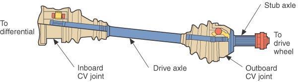
4 1. The drive line assembly (drive axle assembly) transmits from the engine and transmission to the vehicle s wheels. The drive line components also multiply torque, change direction of power flow, and allow different speeds between the driving wheels. Pressure Force Torque

5


6 2. FWD axle shafts are fitted with (CV) joints that transfer uniform torque at a constant speed while operating through a wide range of angles up to 40 degrees. Continuously Variable Common Vehicle Constant Velocity

7

8 3. CV joints allow the of the axle assembly to change as the wheel travels up & down. Length Angle Torque

9


10 4. CV joints are classified by,, and. Location Function Design ATASA 5 th
11 POSITION
12 FUNCTION

13 DESIGN
14 5. joints are nearest the transaxle. joints are nearest the wheels. Outboard Inboard Onboard


15 6. joints are capable of length changes. joints cannot change length. Nixed, Plunge Fixed, Plunge Plunge, Fixed
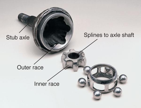
16 7. The is typically an outboard, fixed CV joint with 6 balls in a roller cage.


17 8. CV joints & CV joints are plunging ball types. Double Offset, Cross Groove

18 9. A has 3 trunions fitted with spherical rollers on needle bearings. (plunge or fixed) Trio Tripod Triangle

19 10. FWD shafts can be either equal or unequal length and can be either solid or tubular. Drive Axle Half


20 Intermediate Shafts
21 11. On hard acceleration vehicle s tend to steer toward the side with the longer half shaft. Bump Memory Torque
22 12. A small weight attached to a half shaft can reduce harmonic vibrations. Pamper Damper Camper

23

24 13. CV joints have a higher failure rate characterized by a clicking while cornering. Rear Outboard Inboard


25

26 14. Torn or leaking CV boots should be replaced ASAP along with new grease & clamps. True or False
27 15. Best Practice is to recheck alignment after replacing half shafts. True or False


28 16. Hotchkiss type RWD drive shafts are often fit with joints, known as cardan joints or spicer joints. Universal Rzeppa Ball & Socket
29


30 17. A or external carrier bearing is used on excessively long shafts. Center Support Cross Groove Hanging Bearing


31 18. A yoke is used to allow effective length change of the RWD shaft. Slip Dip Rip

32 19. When universal joint yokes are in the same plane, the joints are said to be. In Phase In Sync In Touch
33 20. Maintaining minimal universal joint is critical to smooth operation. Operating Room Operating Angle Operating Temperature

34
35 21. & binding can be reduced by using canceling angles on the U joints. Vibration Citation Commotion

 Internal,")
36 22. U Joints can be held onto their yokes with either an snap ring, an snap ring, or a combination of the two ring types. (Spicer Mechanics or Detroit/Saginaw Cleveland) Internal, External Intrinsic, Extrinsic Interval, Extrovert

37


38

39


40 23. A joint is also known as a double cross & roller or RWD CV joint. Constant Volume Constant Velocity Common Velocity


41


42 24. A worn extension housing can cause a rear trans fluid leak even with a good seal. Bushing Bearing Shaft

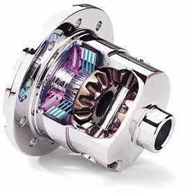
43 25. provide a gear reduction & allow the cornering wheels to turn at different speeds. Transmissions Differentials Transaxles

44
45

46


47 Overhung, Straddle Overhang, Saddle Overhead, Scandal


48 Gearsets can be classified as either: hunting, non hunting, or partial hunting. A non hunting gearset always has the same teeth in contact with each other. A non hunting set is characterized by a whole number ratio such as 3:1, 4:1, 5:1. A hunting gearset does not mesh the same gear teeth during each revolution and would have a decimal ratio such as 2.89:1 or 3.27:1 or 4.11:1. A partial hunting gearset would be characterized by ratios like 2.5:1 or 3.5:1 or 4.5:1.

49
50
51

52 Limited Slip Lost Torque Lever Actuated
53

54


55 SAE 80 or SAE 90 SAE 20 or SAE40 SAE 5W30 or 0W30

56 26. Differentials mesh an input gear with a gear to achieve the final drive reduction. A reduction in speed of a gearset results in an increase of torque through that gearset. Pinion, Ring Spider, Crown Bevel, Worm

57 27. Differential input pinions are either or mounted on bearings. Overhung, Straddle Overhang, Saddle Overhead, Scandal

58 28. differential gearsets have more than one gear in contact at a time in a wiping motion. Hypiod Thyroid Steroid

59 29. Gearsets can be classified as either, or partial hunting. Hunting, Non Hunting Hunting, Some what Hunting Hunting, Fishing


60 30. Rear axle housings are either or carrier in design. Integral, Removable Internal, Detachable Ingenious, Rzeppa
61
62 31. differentials supply the most torque to the axle that s easiest to turn. (has the least traction) Open Closed Ajar

63 32. differentials supply the torque to the axle that has the most traction. Limited Slip Lost Torque Lever Actuated

64 32. differentials supply the torque to the axle that has the most traction. Limited Slip Lost Torque Lever Actuated

65 33. The axle transfers torque from the differential to the vehicle s driving wheels. Booster Shaft Cylinder


66 34. A axle does not drive a vehicle. A axle is one that transfers torque to drive a vehicle. Live, Dead Dead, Live Wanted, Escaped

67 35. Most RWD vehicles have axles that transmit only driving torque. Semi floating Semi driving Semi sonic


68 36. floating axles & floating axles are used in heavy duty vehicles. Three Quarter, Full Five Quarter, Full One Quarter, Full
. Radial.")
69 37. Axle shaft bearings are subjected to both loading and loading (axial). Radial. Thrust Radial, Axial Radial, Axial


70 38. Axle bearings are lubricated by the gear oil in the. (hypoid 80w90) (Limited slip may require a special additive.) Oil Pan Axle Housing Oil Tank

71 39. Noises happen in different modes:,,, and mode. Drive, Cruise, Coast, Float


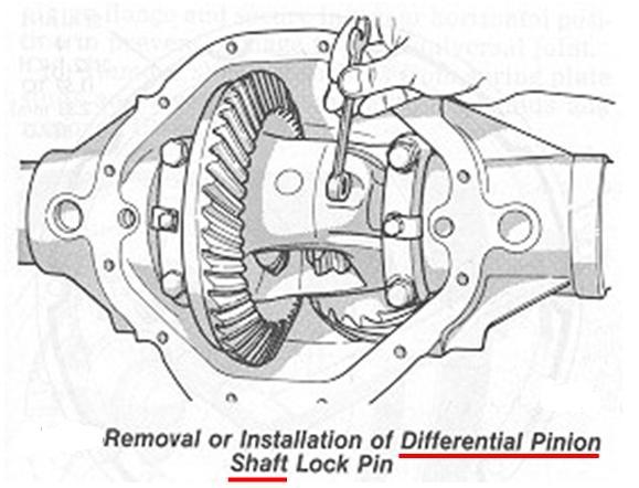
72 40. While removing & replacing an integral carrier differential from the axle housing, a tool called a case must be used to distort the housing just enough to slide the carrier in and out. Shredder Spreader Threader

73


74 41. Differential side gears are held on to axle shafts by shaped washers fit into axle shaft grooves. C F Z

75

76 Systems Repair


77 42. Pinion bearing and gearset are critical checks and possibly adjustments to be made when assembling, servicing, or diagnosing differential complaints. Preload, Backlash Runout, Parallelism End Play, Clearance


78

79 43. A ring gear is never replaced without replacing its mating gear. (wear mated parts) Drive Pinion


80 44. Gearset backlash is measured with a dial indicator on a ring gear tooth, holding the input pinion, and noting the movement while the ring gear. It is then adjusted to meet specs <.004 Hammering Rocking Spinning
81 45. Gearset backlash is adjusted either with or by turning both bearing adjusting. Shims, Nuts
82 46. Turning only 1 adjusting nut or installing only 1 shim will change carrier bearing. Preload Backlash Runout


83 47. Both input pinion bearing & carrier bearing preload is measured with an inch pound wrench connected in such a way to indicate the torque needed to turn the components. Collapsible Spacer Torque Crow s Foot Pipe

84 48. The pattern of gear teeth determines how the two meshed gears will run and describes where on the faces of the teeth the two gears will. Quietly, Contact


85 49. Checking tooth contact pattern is done by the ring gear teeth with a marking compound & turning the input yoke or companion flange in both directions. Contact should be in the middle of the flank, toe, & heel of the ring gear teeth. If not, gearset noise is the result. Painting or Coating

86


87 50. Rear axles use either SAE or gear oil. (GL 4 or GL 5) (Limited slip may require a special additive.) 80 or or or 30

88 51. A bent axle or axle runout can also be a source of rear end vibration. Flange Pinch Weld Overlap

89
90 Now that we re through Keeping in mind that Career Clusters sensibly link education to careers Ask yourself: What careers could be linked to the topics in this slide series? Which of those careers might interest me? How do career clusters relate to my other high school classes? Do I need to change my 4 year plan to fit my desired career?


91


92


93


94

95


96


97


98

99

100

101

102

103

104

105

106
107

108

109

110

111

112

113


114
Advanced Auto Tech. ASE A 3 Test Preparation Clutch & Drive Line Service
 Advanced Auto Tech ASE A 3 Test Preparation Clutch & Drive Line Service The clutch and the drive line both have their own unique symptoms and noises, separate from the transmissions used to change torque
Purposes of a Drive Axle Assembly
 Differentials Purposes of a Drive Axle Assembly To transmit power from the drive shaft to the wheels To turn the power flow 90 degrees on RWD cars To allow the wheels to turn at different speeds while
AUT 231 (A3) MANUAL TRANSMISSION/TRANSAXLE AND DRIVETRAIN
 MANUAL TRANSMISSION/TRANSAXLE AND DRIVETRAIN") AUT 231 (A3) MANUAL TRANSMISSION/TRANSAXLE AND DRIVETRAIN COURSE DESCRIPTION: Prerequisites: TRN 120 Corequisites: None This course covers the operation, diagnosis, and repair of manual transmissions/transaxles,
AUT 231 (A3) MANUAL TRANSMISSION/TRANSAXLE AND DRIVETRAIN COURSE DESCRIPTION: Prerequisites: TRN 120 Corequisites: None This course covers the operation, diagnosis, and repair of manual transmissions/transaxles,
DRIVE AXLE - INTEGRAL HOUSING
 DRIVE AXLE - INTEGRAL HOUSING 1993 Toyota Celica 1993 DRIVE AXLES Toyota Differentials & Axle Shafts - Integral Housing Toyota; Celica All-Trac DESCRIPTION Drive axle assembly is a hypoid type with integral
ATASA 5 th. Wheel Alignment. Please Read The Summary. ATASA 5 TH Study Guide Chapter 47 Pages: Wheel Alignment 64 Points
 ATASA 5 TH Study Guide Chapter 47 Pages: 1403 1423 64 Points Please Read The Summary Before We Begin Keeping in mind the Career Cluster of Transportation, Distribution & Logistics Ask yourself: What careers
Drive Shaft Purposes. Transmits power from the transmission to the differential
 Drive Shafts Drive Shaft Purposes Transmits power from the transmission to the differential Allows the transmission and the rear axle assembly to be at different heights Allows the rear axle to move up
DF 78. HINT: Face the rough side of the thrust washer marked by # to the differential case. INSPECTION
 78 DIFFERENTIAL REAR DIFFERENTIAL CARRIER ASSEMBLY (w/ Differential Lock) Face the rough side of the thrust washer marked by # to the differential case. INSPECTION 1. DIFFERENTIAL SIDE GEAR (w/ LSD Differential)
UNIT III TRANSMISSION SYSTEMS CONTENTS: Clutch-types and construction Gear boxes- manual and automatic Gear shift mechanisms Over drive Transfer box
 UNIT III TRANSMISSION SYSTEMS CONTENTS: Clutch-types and construction Gear boxes- manual and automatic Gear shift mechanisms Over drive Transfer box Fluid flywheel Torque converter Propeller shaft Slip
ASE Practice Test A3 Manual Drive Train
 Clutch Diagnosis and Repair ASE Practice Test A3 Manual Drive Train 1) Which of the following are the three critical clutch pedal measurements? a. Pedal height, apply pressure, and free play b. Pedal free
DRIVE AXLE Nissan 240SX DESCRIPTION & OPERATION AXLE RATIO & IDENTIFICATION AXLE SHAFT & BEARING R & I DRIVE SHAFT R & I
 DRIVE AXLE 1990 Nissan 240SX 1990 DRIVE AXLES Rear Axle - R200 240SX, 300ZX DESCRIPTION & OPERATION The axle assembly is a hypoid type gear with integral carrier housing. The pinion bearing preload adjustment
Front Wheel Drive Notes
 Front Wheel Drive Notes Drive Axle Components Outer CV-joint Allows wheels to steer while axle is rotating Inner CV-joint Allows for suspension changes while axle is rotating Axle shaft Transmits power
M Ring and Pinion Installation
 !!! PLEASE READ ALL OF THE FOLLOWING INSTRUCTIONS CAREFULLY PRIOR TO INSTALLATION. Axle Shaft Removal (1994-2012 Mustang typical) STEP 1: STEP 2: Remove the 10 differential housing cover bolts and drain
SECTION 3A FRONT DRIVE AXLE TABLE OF CONTENTS SPECIFICATIONS GENERAL SPECIFICATIONS. Description Drive Shaft Type. CV Joint Axle Housing Type
 SECTION 3A FRONT DRIVE AXLE TABLE OF CONTENTS Specifications........................ 3A-1 General Specifications.................. 3A-1 Fastener Tightening Specifications......... 3A-2 Component Locator...................
SECTION 3D REAR AXLE TABLE OF CONTENTS
 SECTION 3D REAR AXLE TABLE OF CONTENTS General Description and Operation... 3D-2 Specifications... 3D-2 Fastener Tightening Specifications... 3D-2 Diagnostic Information and Procedures... 3D-3 Component
DRIVE AXLE - 4WD MODELS WITH INTEGRAL HOUSING
 DRIVE AXLE - 4WD MODELS WITH INTEGRAL HOUSING 1988 Toyota Celica DRIVE AXLES Toyota Integral Housing Celica (Rear) DESCRIPTION housing. Drive axle assembly is hypoid type with integral carrier AXLE RATIO
PROPELLER SHAFT & DIFFERENTIAL CARRIER SECTIONPD CONTENTS
 PROPELLER SHAFT & DIFFERENTIAL CARRIER SECTIONPD CONTENTS PREPARATION...2 PROPELLER SHAFT...5 On-Vehicle Service...6 Removal and Installation...7 Inspection...7 Disassembly...7 Assembly...8 ON-VEHICLE
Manual Transmission/Driveline. Final Review
 Manual Transmission/Driveline Final Review 1. The Pressure Plate is a spring-loaded device that presses the clutch disc against the flywheel. 2. The clutch Release Mechanism allows the driver to disengage
G Class Transfer Case. 217 HO 06 Transfer Case (IC GC OP TF)
") G Class Transfer Case 217 HO 06 Transfer Case (IC GC OP TF) 1-30-03 2 These technical training materials are current as of the date noted on the materials, and may be revised or updated without notice.
G Class Transfer Case 217 HO 06 Transfer Case (IC GC OP TF) 1-30-03 2 These technical training materials are current as of the date noted on the materials, and may be revised or updated without notice.
INSPECTION DF 80. Install the rear differential side gear and rear differential spider onto the differential case RH.
 80 INSPECTION 1. INSPECT DIFFERENTIAL PINION AND SIDE GEAR (a) Check that there is no damage to the differential pinion or differential side gear. If the differential pinion and/or differential side gear
CHAPTER 7 FRONT AXLE
 CHAPTER 7 FRONT AXLE 1. STRUCTURE FRONT AXLE 1.1 FRONT AXLE STRUCTURE 704W701A (1) Front Bracket (2) Rear Bracket (3) Center Pin (4) Front Axle Support (5) Bevel Gear Case (6) Front Axle Case (7) Front
REAR AXLE Click on the applicable bookmark to selected the required model year
 REAR AXLE 27-2 REAR AXLE General Information GENERAL INFORMATION 27100010118 The rear axle is a banjo-type semi-floating type. The axle shaft bearings are: *Single taper bearings for vehicles without
DF 15. DIFFERENTIAL 1GR-FE FRONT DIFFERENTIAL CARRIER ASSEMBLY (for 4WD) REMOVAL
 REMOVAL") DIFFERENTIAL 1GR-FE FRONT DIFFERENTIAL CARRIER ASSEMBLY (for 4WD) 15 REMOVAL 1. REMOVE FRONT WHEELS 2. REMOVE REAR ENGINE UNDER COVER ASSEMBLY (a) Remove the 6 bolts and engine under cover assembly. 3.
DIFFERENTIAL 1GR-FE FRONT DIFFERENTIAL CARRIER ASSEMBLY (for 4WD) 15 REMOVAL 1. REMOVE FRONT WHEELS 2. REMOVE REAR ENGINE UNDER COVER ASSEMBLY (a) Remove the 6 bolts and engine under cover assembly. 3.
Rear Drive Axle and Differential
 Page 1 of 13 Rear Drive Axle and Differential GENERAL Item Part Number Description A - Electronic rear differential B - Open rear differential 1 - Rear driveshaft 2 - Electronic rear differential 3 - RH
DF 43 DIFFERENTIAL REAR DIFFERENTIAL CARRIER ASSEMBLY REMOVAL
 DIFFERENTIAL REAR DIFFERENTIAL CARRIER ASSEMBLY 43 REMOVAL 1. DISCONNECT CABLE FROM NEGATIVE BATTERY TERMINAL 2. REMOVE REAR WHEEL 3. DRAIN BRAKE FLUID 4. REMOVE REAR BRAKE DRUM SUB-ASSEMBLY (See page
REAR AXLE GROUP CONTENTS GENERAL DESCRIPTION DRIVE SHAFT ASSEMBLY REAR AXLE DIAGNOSIS
 27-1 GROUP 27 CONTENTS GENERAL DESCRIPTION 27-2 DIAGNOSIS 27-2 INTRODUCTION 27-2 TROUBLESHOOTING STRATEGY 27-2 SYMPTOM CHART 27-3 SYMPTOM PROCEDURES 27-3 SPECIAL TOOLS 27-8 ON-VEHICLE SERVICE 27-12 TOTAL
1994 Mitsubishi Eclipse GS
 APPLICATIONS CHRYSLER MOTORS MANUAL TRANS OVERHAUL - MITSUBISHI W5M & W6M SERIES MANUAL TRANSMISSIONS Mitsubishi W5M31, TRANSMISSION APPLICATIONS (CHRYSLER MOTORS) Vehicle Application Transmission Model
TION AND OPERATION Procedure revision date: 01/22/1999
 TION AND OPERATION Procedure revision date: 01/22/1999 Main Components and Functions AX4S Main Components http://www.fordtechservice.dealerconnection.com/pubs/content/~wsww/~mus~len/20/sww71006.htm (1
LIFT TRUCK SERIES: G35S-2 G40S-2 G45S-2 G40SC-2 G45SC-2 G50SC-2. November 15, 2000 CODE 3150 LT3150-L0 SUBJECT: NEW DRIVE AXLE
 LIFT TRUCK SERIES: G35S-2 G40S-2 G45S-2 G40SC-2 G45SC-2 G50SC-2 November 15, 2000 CODE 3150 LT3150-L0 SUBJECT: NEW DRIVE AXLE A new drive axle has been introduced in the above model lift trucks. The purpose
Model 4360 Teardown and Reassembly Instructions
 Clean the outside surface of the transaxle. Place the shifter in neutral position. Remove detent cover screw (item 3), detent cover (item 4), detent springs (item 5), and detent balls (item 6). Use a magnet
A 1 SERVICE SPECIFICATIONS
 A1 A2 Clutch CLUTCH Specifications Pedal height (from asphalt sheet) Release point (from pedal stroke end position) Push rod play at pedal top Pedal freeplay Disc rivet head depth Disc runout Diaphragm
PROPELLER SHAFTS 16-1 PROPELLER SHAFTS CONTENTS
 Z PROPELLER SHAFTS 16-1 PROPELLER SHAFTS CONTENTS page GENERAL INFORMATION... 1 PROPELLER SHAFT REPLACEMENT... 7 SERVICE DIAGNOSIS/PROCEDURES... 3 page TORQUE SPECIFICATIONS... 14 UNIVERSAL JOINT REPLACEMENT...
REAR AXLE Click on the applicable bookmark to selected the required model year
 REAR AXLE 27-1 REAR AXLE CONTENTS GENERAL INFORMATION.................. 2 SERVICE SPECIFICATIONS................. 3 LUBRICANTS.............................. 3 SEALANTS AND ADHESIVES.............. 4 SPECIAL
2007 Hummer H Driveline/Axle Propeller Shaft - H3. Fastener Tightening Specifications Specification Application
 2007 Driveline/Axle Propeller Shaft - H3 SPECIFICATIONS FASTENER TIGHTENING SPECIFICATIONS Fastener Tightening Specifications Specification Application Metric English Bolt - Front Propeller Shaft CV Joint
SECTION 17 SUSPENSION CONTENTS FRONT SUSPENSION REAR SUSPENSION MAINTENANCE SERVICES
 SECTION 17 SUSPENSION CONTENTS 17-1. FRONT SUSPENSION...................................... 17-2 17-2. REAR SUSPENSION...................................... 17-15 17-3. MAINTENANCE SERVICES................................
1. General Description
 1. General Description A: SPECIFICATIONS 1. Type Transmission gear ratio Front reduction gear Rear reduction gear 2. TRANSMISSION GEAR OIL Recommended oil Final Transfer 5-forward speeds with synchromesh
REMOVAL & INSTALLATION
 REMOVAL & INSTALLATION AXLE SHAFTS & BEARINGS Removal CAUTION: Failure to turn off air suspension power before raising vehicle may result in unexpected inflation or deflation of air springs. DO NOT reconnect
1999 Toyota RAV DRIVE AXLES AWD & FWD Axle Shafts - RAV4 & RWD Axle Shafts - MR2. AWD & FWD Axle Shafts - RAV4 & RWD Axle Shafts - MR2
 1999-2000 DRIVE AXLES AWD & FWD Axle Shafts - RAV4 & RWD Axle Shafts - MR2 DESCRIPTION & OPERATION On RAV4 models, axle shafts transfer power from transaxle to front wheels (FWD), or front and rear wheels
Installation Kit Instructions
 Installation Kit Instructions Please read completely before beginning. Over the years we have gathered information from Gleason gear design manuals, Dana Spicer instruction manuals, technical bulletins,
AXLE SHAFTS - 2.2L Toyota Celica DESCRIPTION TROUBLE SHOOTING REMOVAL, DISASSEMBLY, REASSEMBLY & INSTALLATION AXLE SHAFTS
 AXLE SHAFTS - 2.2L 1994 Toyota Celica 1994 DRIVE AXLES Toyota FWD Axle Shafts Celica 2.2L 4 Cyl DESCRIPTION Axle shafts transfer power from transaxle to the front wheels. Axle shaft consists of axle shaft
PPM-D44538RJK JK Rear 5.38 Ring and Pinion Installation Instructions Version 1
 PPM-D44538RJK JK Rear 5.38 Ring and Pinion Installation Instructions Version 1 GENERAL NOTES: Gear set up and installation should be performed by someone experienced in gear and axle set up Special tools
DRIVE AXLE Volvo 960 DESCRIPTION & OPERATION AXLE IDENTIFICATION DRIVE AXLES Volvo Differentials & Axle Shafts
 DRIVE AXLE 1994 Volvo 960 1994 DRIVE AXLES Volvo Differentials & Axle Shafts 960 DESCRIPTION & OPERATION All 960 station wagon models use type 1041 rear axle assembly. All 960 4-door models use type 1045
REAR AXLE AND SUSPENSION RA 1
 REAR AXLE AND SUSPENSION RA1 RA2 REAR AXLE AND SUSPENSION Troubleshooting TROUBLESHOOTING Problem Possible cause Remedy Page Wanders/pulls Tires worn or improperly inflated Replace tires or inflate to
2007 Hummer H Driveline/Axle Wheel Drive Shafts - H3. Fastener Tightening Specifications Specification Application
 2007 Driveline/Axle Wheel Drive Shafts - H3 SPECIFICATIONS FASTENER TIGHTENING SPECIFICATIONS Fastener Tightening Specifications Specification Application Metric English Front Wheel Drive Shaft Nut 260
TO INDEX DIFFERENTIAL FRONT DIFFERENTIAL CARRIER OIL SEAL (4WD) FRONT DIFFERENTIAL CARRIER ASSEMBLY (4WD) REAR DIFFERENTIAL CARRIER OIL SEAL
 FRONT DIFFERENTIAL CARRIER ASSEMBLY (4WD) REAR DIFFERENTIAL CARRIER OIL SEAL") TO INDEX DRIVE LINE / AXLE DIFFERENTIAL DIFFERENTIAL SYSTEM PRECAUTIONS.............................................. OPERATION CHECK......................................... PROBLEM SYMPTOMS TABLE.................................
TO INDEX DRIVE LINE / AXLE DIFFERENTIAL DIFFERENTIAL SYSTEM PRECAUTIONS.............................................. OPERATION CHECK......................................... PROBLEM SYMPTOMS TABLE.................................
This file is available for free download at
 This file is available for free download at http://www.iluvmyrx7.com This file is fully text-searchable select Edit and Find and type in what you re looking for. This file is intended more for online viewing
INSTALLATION KIT INSTRUCTIONS
 INSTALLATION KIT INSTRUCTIONS Please read completely before beginning This installation guide was written to provide the novice and professional with easy guidelines for differential setup. Over the years
Critical Areas of Setup: Although there are many steps to differential repair, there are 4 critical areas of setup that all differentials share:
 DISASSEMBLY: Integral style with rear cover (aka salisbury) 1. Support vehicle or rearend on suitable lift or stands. 2. Drain oil by removing differential cover. 3. Remove wheels, brake drums, rotors
DIFFERENTIALS & AXLE SHAFTS
 DIFFERENTIALS & AXLE SHAFTS 2001 Chevrolet Camaro 2000-01 DRIVE AXLES General Motors Differentials & Axle Shafts Chevrolet; Camaro Pontiac; Firebird DESCRIPTION & OPERATION Drive axle is a semi-floating,
REAR DIFFERENTIAL LOCATION INDEX
 2007 DRIVELINE/AXLES Differential - MX-5 Miata REAR DIFFERENTIAL LOCATION INDEX Fig. 1: Identifying Location Of Rear Differential Components DIFFERENTIAL OIL INSPECTION 1. Park the vehicle on level ground
DISASSEMBLY AND ASSEMBLY
 205-03-1 Front Drive Axle/Differential Ford 8.8-Inch Ring Gear 205-03-1 DISASSEMBLY AND ASSEMBLY Axle Front Drive Special Tool(s) 2-Jaw Puller 205-D072 (D97L-4221-A) Special Tool(s) Carrier Bearing Replacer
1999 F-150/250 Workshop Manual
 Page 1 of 30 SECTION 205-03: Front Drive Axle/Differential Ford 8.8-Inch Ring Gear 1999 F-150/250 Workshop Manual DISASSEMBLY AND ASSEMBLY Procedure revision date: 01/08/2003 Axle Front Drive Special Tool(s)
Steer Axles. Spicer. Service Manual. AXSM-0070 November Front Drive Steer Axle Model 60
 Spicer Steer Axles Service Manual AXSM-0070 November 2017 Front Drive Steer Axle Model 60 General Information The description and specifications contained in this service publication are current at the
SECTION steering mechanism
 07-302.01/ 1 2011MR17 SECTION 07-302.01 GENERAL Description See Figure 1. The includes the steering wheel (1), the steering column, the miter box (3), the steering shafts (2 and 4), and the drag link (7).
DF 47 DIFFERENTIAL REAR DIFFERENTIAL CARRIER ASSEMBLY REMOVAL
 47 REMOVAL 1. DISCONNECT CABLE FROM NEGATIVE BATTERY TERMINAL 2. REMOVE REAR WHEEL 3. DRAIN BRAKE FLUID Immediately wash off any brake fluid that comes into contact with any painted surfaces. 4. DRAIN
SECTION Front Drive Axle/Differential
 205-03-i Front Drive Axle/Differential 205-03-i SECTION 205-03 Front Drive Axle/Differential CONTENTS PAGE Axle... 205-03-2 205-03-2 Front Drive Axle/Differential 205-03-2 Axle Special Tool(s) C-Frame
Drive pinion and ring gear,
 Page 1 of 38 39-166 Drive pinion and ring gear, adjusting General notes: Drive pinion and ring gear must be very carefully adjusted to ensure long service life and smooth running. At the factory, drive
13. DRIVE TRAIN 13-0 DRIVE TRAIN MXU 500
 13 DRIVE TRAIN SERVICE INFORMATION------------------------------------------------ 13-2 TROUBLESHOOTING----------------------------------------------------- 13-2 FRONT DRIVE SHAFT REMOVAL/INSPECTION/ INSTALLATION
Section II REAR AXLE CONTENTS
 REAR AXLE 1 Section II REAR AXLE CONTENTS Page Removal of Differential Carrier Assembly 5 Removing Drive Gear and Case Assembly 6 Drive Pinion and Bearing Disassembly 8 Pinion Bearing Pre-Load and Pinion
SPICER MODEL44 TRAC-LOK LIMITED SLIP DIFFERENTIAL FORT WAYNE, INDIANA
 SPICER MODEL44 TRAC-LOK LIMITED SLIP DIFFERENTIAL FORT WAYNE, INDIANA GENERAL INFORMATION IMPORTA NT SAFETY NOTICE Should an axle assembly require component parts replacement, it is recommended that "Original
4. Rear Differential REAR DIFFERENTIAL
 DIFFERENTIALS 4. Rear Differential A: REMOVAL 1) Set the vehicle on a lift. 2) Disconnect the ground cable from battery. 3) Move the select lever or gear shift lever to N. 4) Release the parking brake.
PROPELLER SHAFT & DIFFERENTIAL CARRIER SECTIONPD CONTENTS IDX. PROPELLER SHAFT...3 Preparation...3 C200. REAR FINAL DRIVE...40 Preparation...
 PROPELLER SHAFT & DIFFERENTIAL CARRIER SECTIONPD GI MA EM LC EC CONTENTS FE PROPELLER SHAFT...3 Preparation...3 SPECIAL SERVICE TOOLS...3 Noise, Vibration and Harshness (NVH) Troubleshooting...4 NVH TROUBLESHOOTING
Installation Instructions for the Tera low range Dana 20 (LOW20)
") Installation Instructions for the Tera low range Dana 20 (LOW20) Tera Manufacturing, Inc. 5251 South Commerce Dr. Murray, Utah 84107 Phone/801.288.2585 Fax/801.288.2571 www.teraflex.biz Attention: Verify
Installation Instructions for the Tera low range Dana 20 (LOW20) Tera Manufacturing, Inc. 5251 South Commerce Dr. Murray, Utah 84107 Phone/801.288.2585 Fax/801.288.2571 www.teraflex.biz Attention: Verify
SA 82 Front Differential (Disassembly and Assembly of Differential w/ ADD) Disassembly and Assembly of Differential (with A.D.D.)
 Disassembly and Assembly of Differential (with A.D.D.)") SA82 SUSPENSION AND AXLE Disassembly and Assembly of Differential (with A.D.D.) DISASSEMBLY OF DIFFERENTIAL 1. REMOVE ACTUATOR (a) Remove the four bolts. (b) Using a hammer, remove the actuator. SA83 2.
SA82 SUSPENSION AND AXLE Disassembly and Assembly of Differential (with A.D.D.) DISASSEMBLY OF DIFFERENTIAL 1. REMOVE ACTUATOR (a) Remove the four bolts. (b) Using a hammer, remove the actuator. SA83 2.
DIAGNOSIS AND TESTING
 205-02B-1 DIAGNOSIS AND TESTING Rear Drive Axle and Differential Special Tool(s) Dial Indicator Gauge with Holding Fixture 100-002 (TOOL-4201-C) or equivalent 205-02B-1 4 Has the driveline system been
FRONT AXLE - 9 1/4 AA
 DR FRONT AXLE - 9 1/4 AA 3-45 FRONT AXLE - 9 1/4 AA TABLE OF CONTENTS page FRONT AXLE - 9 1/4 AA DESCRIPTION......................... 45 OPERATION........................... 45 DIAGNOSIS AND TESTING................
DIM Drive Train Systems
 2014 NATEF JOB TASKS COMPLETION REQUIREMENT: P1-95% P2-70% P3-25% Student Name: DETAILED COURSE CONTENT II. DRIVE TRAIN A. CLUTCH -- The student will be able to: P1 P2 P3 Level Date 1. Identify causes
Take off case cover.
 33 14 520 Replacing complete locking differential (Type M) - final drive removed - Removing and installing final drive, included in Repair Manual MF, model-dependent, from '85, refer to 33 10 010. Drain
REAR AXLE <4WD> GROUP 27B 27B-1 CONTENTS REAR AXLE HUB ASSEMBLY... GENERAL INFORMATION... SERVICE SPECIFICATIONS... LUBRICANTS...
 -1 GROUP GEERAL IFORMATIO........ SERVICE SPECIFICATIOS....... LUBRICATS.................. SEALAT AD ADHESIVE........ SPECIAL TOOLS................ O-VEHICLE SERVICE........... REAR AXLE TOTAL BACKLASH
TROUBLESHOOTING SPECIAL TOOL ASSEMBLY AND ADJUSTMENT
 1 INDEX Models FD, FE, FF and SG REAR AXLE 10-1 10-108E-07 CHAPTER 10 REAR AXLE Models FD, FE, FF and SG TROUBLESHOOTING...10-2 10 SPECIAL TOOL...10-3 WHEEL HUB AND RELATED PARTS DISASSEMBLY...10-7 INSPECTION...10-9
DIFFERENTIAL AND DRIVELINE
 ZG DIFFERENTIAL AND DRIVELINE 3-1 DIFFERENTIAL AND DRIVELINE CONTENTS page 181 FBI AXLE... 15 194 RBI AXLE... 50 page 216 RBA AXLE... 87 PROPELLER SHAFTS... 1 PROPELLER SHAFTS INDEX page GENERAL INFORMATION
PROPELLER SHAFT GROUP CONTENTS GENERAL DESCRIPTION PROPELLER SHAFT PROPELLER SHAFT DIAGNOSIS SPECIFICATIONS...
 25-1 GROUP 25 CONTENTS GENERAL DESCRIPTION 25-2 DIAGNOSIS 25-2 INTRODUCTION TO DIAGNOSIS 25-2 DIAGNOSTIC TROUBLESHOOTING STRATEGY 25-2 SYMPTOM CHART 25-2 SYMPTOM PROCEDURES 25-3 SPECIAL TOOL 25-4 25-4
1. General Description
 1. General Description A: SPECIFICATION 1. MANUAL TRANSMISSION AND FRONT DIFFERENTIAL Type Transmission gear ratio Front reduction gear Rear reduction gear Front differential Center differential Final
25-1 PROPELLER SHAFT CONTENTS GENERAL INFORMATION... 2 SEALANT... 2 SERVICE SPECIFICATIONS... 2 SPECIAL TOOL... 2 LUBRICANT... 2 PROPELLER SHAFT...
 25-1 PROPELLER SHAFT CONTENTS GENERAL INFORMATION... 2 SERVICE SPECIFICATIONS... 2 LUBRICANT... 2 SEALANT... 2 SPECIAL TOOL... 2 PROPELLER SHAFT... 3 25-2 PROPELLER SHAFT - General Information/Service
REAR AXLE <4WD> GROUP 27B 27B-1 CONTENTS REAR AXLE HUB ASSEMBLY... 27B-8 GENERAL INFORMATION... 27B-2 SERVICE SPECIFICATIONS...
 27B-1 GROUP 27B COTETS GEERAL IFORMATIO........ 27B-2 SERVICE SPECIFICATIOS....... 27B-3 LUBRICATS.................. 27B-3 SEALAT AD ADHESIVE........ 27B-3 SPECIAL TOOLS................ 27B-4 O-VEHICLE
Additions, Revisions, or Updates
 1 SUBJECT DATE Model 4 Single Model 4 Rear Tandem Pinion Bearing Repair October 2013 Additions, Revisions, or Updates Publication Number / Title Platform Section Title Change DDC-SVC-MAN-0141 Detroit Axles
SISU MP-330 DRIVE GEAR. Maintenance Manual
 SISU MP-330 DRIVE GEAR Maintenance Manual Sisu Axles, Inc. Autotehtaantie 1 PO Box 189 Fin-13101 Hameenlinna Finland Phone +358 204 55 2999 Fax +358 204 55 2900 MP330DG.PDF (4/2007) TABLE OF CONTENTS
2002 F-Super Duty /Excursion Workshop Manual
 Page 1 of 5 SECTION 205-02D: Rear Drive Axle/Differential Ford 10.50-Inch Ring Gear 2002 F-Super Duty 250-550/Excursion Workshop Manual DIAGNOSIS AND TESTING Procedure revision date: 02/02/2005 Rear Drive
REMOVAL & INSTALLATION
 Page 1 of 6 REMOVAL & INSTALLATION AXLE SHAFTS Removal Raise and support vehicle. Remove front wheels. Remove engine undercovers. Remove cotter pin and lock nut cap. See Fig. 2. Apply brakes and remove
UNIT -I. Ans: They are specified by the no. of strands & the no. of wires in each strand.
 VETRI VINAYAHA COLLEGE OF ENGINEERING AND TECHNOLOGY, THOTTIAM, NAMAKKAL-621215. DEPARTMENT OF MECHANICAL ENGINEERING SIXTH SEMESTER / III YEAR ME6601 DESIGN OF TRANSMISSION SYSTEM (Regulation-2013) UNIT
PROPELLER SHAFT / / PROPELLER SHAFT GENERAL OVERVIEW AND OPERATION PROCESS 1. SPECIFICATION...
 3310-01/3310-00/3310-06 GENERAL 1. SPECIFICATION... 3 OVERVIEW AND OPERATION PROCESS 1. OVERVIEW... 2. COMPONENT LOCATOR... 3310-01 FRONT... 3310-06 REAR... 3310-00 DISASSEMBLY AND REASSEMBLY PROPELLER
SISU DP-330 DRIVE GEAR. Maintenance Manual
 SISU DP-330 DRIVE GEAR Maintenance Manual Sisu Axles, Inc. Autotehtaantie 1 PO Box 189 Fin-13101 Hameenlinna Finland Phone +358 204 55 2999 Fax +358 204 55 2900 DP330DG.PDF (3/2007) TABLE OF CONTENTS
2005 Mustang Workshop Manual
 SECTION 205-00: Driveline System General Information 2005 Mustang Workshop Manual GENERAL PROCEDURES Procedure revision date: 07/29/2004 Driveline Angle Inspection Printable View (122 KB) Special Tool(s)
SERVICE MANUAL STEERING AND RIGID DRIVE AXLES SERIES 068. Date Revision Description Owner 06/10/ Document emission PM
 SERVICE MANUAL STEERING AND RIGID DRIVE AXLES SERIES 068 Date Revision Description Owner 06/10/09 1.0 Document emission PM COMER INDUSTRIES Axles & Wheel Drive Units Via Magellano, 37-42046 Reggiolo (RE)
615 Service Manual SERVICE MANUAL. 615 Series Axle
 SERVICE MANUAL 615 Series Axle Issue 1 - February 2002 CONTENT: 1 INTRODUCTION... Page - 1-2 GENERAL DESCRIPTION... Page - 1-3 IDENTIFICATION... Page - 1-4 GENERAL SERVICE INFORMATION... 4.1 Routine Maintenance...
11.AWD Transfer System
 W1860BE.book Page 54 Tuesday, January 28, 2003 11:01 PM 11.AWD Transfer System A: MPT MODELS 1. GENERAL This all-wheel-drive (AWD) transfer system uses an electronically controlled multi-plate type transfer
MANUAL TRANSAXLE Return to Main Table of Contents
 MANUAL TRANSAXLE Return to Main Table of Contents GENERAL... 2 MANUAL TRANSAXLE CONTROL... 12 SHIFT LEVER ASSEMBLY... 14 MANUAL TRANSAXLE... 15 MANUAL TRANSAXLE ASSEMBLY... 17 FIFTH SPEED SYNCHRONIZER
GEAR CONTENTS POWER TRANSMISSION GEAR TYPES OF GEARS NOMENCLATURE APPLICATIONS OF GEARS VELOCITY RATIO GEAR TRAINS EXAMPLE PROBLEMS AND QUESTIONS
 GEAR CONTENTS POWER TRANSMISSION GEAR TYPES OF GEARS NOMENCLATURE APPLICATIONS OF GEARS VELOCITY RATIO GEAR TRAINS EXAMPLE PROBLEMS AND QUESTIONS GEAR.. Power transmission is the movement of energy from
COMPONENTS REAR DIFFERENTIAL COMPONENTS
 COMPONENTS REAR DIFFERENTIAL COMPONENTS REMOVAL 1. Drain the differential gear oil. 2. Remove the rear disk brake. 3. Remove the parking brake and cable. 4. Remove the stabilizer bar. 5. Pull out the
SERVICE MANUAL. 915 Series Axle
 SERVICE MANUAL 915 Series Axle Issue 1 September 2003 CONTENT: 1 INTRODUCTION Page 3-2 GENERAL DESCRIPTION Page 3-3 IDENTIFICATION Page 3-4 GENERAL SERVICE INFORMATION Page 5 -.1 4.1 Routine Maintenance
FRONT AXLE Click on the applicable bookmark to selected the required model year. Purchased from
 FRONT AXLE Click on the applicable bookmark to selected the required model year. 26-1 FRONT AXLE CONTENTS GENERAL INFORMATION... 2 SERVICE SPECIFICATIONS... 4 LUBRICANTS... 4 SEALANTS... 5 SPECIAL TOOLS...
Take off case cover.
 33 14 520 Removing complete locking differential. (Type K) - final drive removed - Removing and installing final drive, refer to 33 10 010 Drain off fluid. Secure final drive to special tool 33 1 010 (retaining
ME6601 DESIGN OF TRANSMISSION SYSTEMS
 SYED AMMAL ENGINEERING COLLEGE (Approved by the AICTE, New Delhi, Govt. of Tamilnadu and Affiliated to Anna University, Chennai) Established in 1998 - An ISO 9001:2008 Certified Institution Dr. E.M.Abdullah
Copyright Notice. Small Motor, Gearmotor and Control Handbook Copyright Bodine Electric Company. All rights reserved.
 Copyright Notice Small Motor, Gearmotor and Control Handbook Copyright 1993-2003 Bodine Electric Company. All rights reserved. Unauthorized duplication, distribution, or modification of this publication,
Lecture (7) on. Gear Measurement. By Dr. Emad M. Saad. Industrial Engineering Dept. Faculty of Engineering. Fayoum University.
 on. Gear Measurement. By Dr. Emad M. Saad. Industrial Engineering Dept. Faculty of Engineering. Fayoum University.") 1 Lecture (7) on Gear Measurement Fayoum University By Dr. Emad M. Saad Industrial Engineering Dept. Faculty of Engineering Fayoum University Faculty of Engineering Industrial Engineering Dept. 2015-2016
1 Lecture (7) on Gear Measurement Fayoum University By Dr. Emad M. Saad Industrial Engineering Dept. Faculty of Engineering Fayoum University Faculty of Engineering Industrial Engineering Dept. 2015-2016
INSTALLATION AND PARTS MANUAL
 INSTALLATION AND PARTS MANUAL FOR JOHN DEERE PS TRACTORS NOTE: This manual covers mounting and control group installation, and parts specific to this winch on the specified tractor. For all other winch
DISASSEMBLY AND ASSEMBLY (Continued)
") 205-03-23 Front Drive Axle/Differential Ford 8.8-Inch Ring Gear 205-03-23 49. Measure the ring gear backlash at four places to obtain a consistent reading. 1 Mount the special tools on the indicator base.
205-03-23 Front Drive Axle/Differential Ford 8.8-Inch Ring Gear 205-03-23 49. Measure the ring gear backlash at four places to obtain a consistent reading. 1 Mount the special tools on the indicator base.
SERVICE MANUAL MODEL FRONT CARRIER TYPE
 SPICER AXLE SERVICE MANUAL MODEL FRONT CARRIER TYPE INDEX Page LUBRICATION... 3 SPECIAL SERVICE TOOLS...................................................... 4 AXLE IDENTIFICATION... 5 SHAFT BEARINGS AND
TC Series Rear Axle. Table of Contents. TC Series Rear Axle
 TC Series Rear Axle Table of Contents Table of Contents...1 Safety...2 Warnings and Cautions...2 Introduction...2 Description of Operation...2 Service Parts and Axle Identification...3 Special Tools...3
Inspection & Diagnosis
 History The Rzeppa CV joint was patented by Alfred H. Rzeppa in 1928. These early designs had six tracks in the housing and race, and a cage with six balls just like the modern version. These early designs
2007 Hummer H Driveline/Axle Rear Drive Axle - H3. Axle Preload and Backlash Specifications Specification Application
 2007 Driveline/Axle Rear Drive Axle - H3 SPECIFICATIONS AXLE PRELOAD AND BACKLASH SPECIFICATIONS Axle Preload and Backlash Specifications Specification Application Metric English Backlash 0.08-0.25 mm