Quick-start. Normal Mode Backlight Switch Screens Stop Watch. Setup Mode. Enter Setup Switch Screens. or Scroll Value. Next Digit.
|
|
|
- Christopher Skinner
- 5 years ago
- Views:
Transcription

1
2 2
3 Quick-start Normal Mode Backlight Switch Screens Stop Watch Setup Mode Data Reset Enter Setup Switch Screens Scroll Value Next Digit Reset Ride Data Adjust Trip Distance Mode Enter / Exit or Scroll Value 3
4 A Note to You Trail Tech brings functionality and life to your motor vehicle with high quality and innovation. To ensure long and trouble-free operation, this User s Manual contains valuable information about how to operate and maintain your digital gauge properly. Please read this manual carefully. If you call to request service for your Striker digital gauge, you need the date of purchase, dealer s name, address, and telephone number. Warranty service requires proof of purchase. PURCHASE DATE DEALER NAME DEALER ADDRESS DEALER PHONE Keep this book and sales slip together for future reference. 4
5 Precautions WARNING Read all instructions before using Striker. Avoid contact with gasoline, degreasers or other chemical cleaners. When installing radiator hose temperature sensors, make sure it fits BEFORE cutting the radiator hose. Do not leave the main unit in direct sunlight when not riding. Striker can be used in the rain but should not be used underwater. Do not wash with pressure washer. When installing Striker, disconnect the vehicle battery. Check gap between speed sensor and magnet periodically. Do not bend, twist, kink or abuse the sensor cables. To reduce the risk of injury, do not disassemble Striker or its accessories. PAY ATTENTION TO THE TRAIL! 5
6 Specifications FUNCTION Current Speed Average Speed Maximum Speed (Trip) Distance Odometer Voltage Minimum Voltage Maximum Voltage Hourmeter / Clock Ride Time Stop Watch Accum. Ride Time Air Temperature Engine Temperature Max Engine Temp Oil Reminder Care Reminder Low Battery Tire Size ICON UNITS KM/H or M/H KM/H or M/H KM/H or M/H KM or M KM or M VAC/VDC VAC/VDC VAC/VDC H:M:S H:M:S H:M:S H:M:S ºC or ºF ºC or ºF ºC or ºF KM/H or M/H KM/H or M/H 3V mm RANGE h or 24h 0:0:0-9999:59 0:0:0-9999:59 0:0:0-9999: º 0-999º 0-999º ~ 1 year life mm 6
7 Specifications PHYSICAL FEATURE Speed/Distance Sensor Temperature Sensors Voltage Sensor Remote Thumb Switch Backlight Product Dimensions Screen Dimensions Product Weight Wheel Circumference Operation Temperature Storage Temperature Battery External Power Input Critical Environment DESCRIPTION Non-contact Magnetic Sensor External Ambient and Engine Thermistor Sensors Red/Black Power Wire Optional, Mirrors Main Buttons 5 White LED Group x59.46x23.7mm WxHxD (4.21x2.34x0.93 ) x 28.6mm (3.1 x 1.13 ) 3.9 oz. (110 grams) (0.24 lbs.) 0 to 3999 mm 0 C to 60 C (32 F to 140 F) -20 C to 80 C (-4 F to 176 F) 3V CR2032 (About 1 Year life) VAC (No Polarity) VDC (No Polarity) Amber/Red LED Alert System 7
8 Physical Features Striker Computer: Main Computer: The Striker computer has 3 buttons and 2 LED s. LEDs: Amber Warning LED: Red Danger LED: Voltage [Flash], Temperature [Solid] Voltage [Flash], Temperature [Solid] Remote Switch: Duplicates buttons on the main computer (sold separately.) REMOTE AMBER LED RED LED TOP MIDDLE BOTTOM LEFT BUTTON CENTER BUTTON RIGHT BUTTON 8
9 Physical Features The Wires: Temperature Sensor: The temperature sensor is mounted in the radiator hose or cylinder head. Remote Switch: Connect the handlebar remote switch accessory (sold separately) to this connector. The remote switch mirrors the buttons on the main unit, for accessibility closer to the hand while riding. Ambient Temperature Sensor Power Cable: The power wire connects anywhere in the vehicle s electrical circuit, or straight to the battery terminals. Speed Sensor: The speed sensor is mounted to the brake caliper on the wheel. Without the speed sensor mounted, Striker cannot display speed or gather distance data. 9
10 Physical Features Reset Button: Use of the reset button will erase data for the current ride including stop watch and trip distance. ODO and ART are permanent. RESET BUTTON BATTERY MOUNTING HOLES Internal Battery: Striker has an internal 3.0V watch type battery (#CR2032). The computer can be run from the internal battery without being connected to a vehicle power source. For proper, full-featured use (LEDs and voltage readouts), connect to vehicle power. To change the battery, unscrew the battery cap on the back of the computer with a coin. Make sure the positive side of the battery is facing up when replaced. REPLACE WITH BATTERY MODEL NUMBER #CR
11 Physical Features Bar Mounting: Place nuts and bolts as shown in picture. Temperature Sensors: Please see-model-specific instructions for mounting procedure. RADIATOR HOSE SPARK PLUG TEMP. SENSOR Cylinder Head Temperature Sensor for air-cooled machines. Temperature Sensor in-line in radiator hose for water-cooled machines. 11
12 DRILL TEMPLATE SCALE 1:1 Physical Features Flat/Surface Mount: There are two screw holes on the back of Striker. Use the included M4 bolts to mount to any flat surface. 40mm Drill Size: 4.2mm If other than provided screws are used, make sure they are not too long for mounting holes. Screws that are too long will damage internal components of Striker mm RESET 59.5mm Mounting Hole Accepts M4 Bolts 12 40mm
13 Physical Features 12 Volt Systems: Connect to 12 volt system: The backlight will be 5x brighter. The temperature and voltage indicator LEDs will be enabled. The voltage readout will function. OPTION 1) BATTERY WIRED: Connect the power cables directly to the vehicle s 12 volt battery. OPTION 2) SYSTEM TAP: As an alternative to running wires all the way to the battery, it is possible to tap into the electrical system. It is best to connect so power is not interrupted by the key switch. The LO indicator will activate if voltage drops below 2.45V. Striker draws too little power to drain the vehicle battery. Striker is polarity independent. Power Wire 13
14 Physical Features ATV Sensor/Magnet Installation: Striker needs two things to be able to collect distance data: 1. A magnet placed on the spinning part of the wheel. 2. A speed sensor, placed on the stationary part of the wheel. ATV Magnet Bolt The magnet spins around tripping the sensor switch each time-- giving Striker speed, distance and time data. The magnet is installed on the brake rotor because it spins with the wheel. The provided magnetic bolt can simply replace a stock rotor bolt (see above picture). If that will not work, glue the spare magnet in a hole on the ATV Speed Sensor brake rotor. (JB Weld or a similar slow-cure epoxy works well.) 14 After the magnet is in, the sensor is placed on a nonspinning part the wheel, rotor shield, or provided bracket.
15 Physical Features Motorcycle Sensor/Magnet Installation: Motorcycles, like ATVs, need a magnet placed on the spinning part of the wheel and the sensor installed to a nonspinning part. The magnet typically gets bolted or glued to the brake rotor. The speed sensor wire should come from the back of the Magnet About to Pass Under Sensor computer, be cable-tied to the brake line as it travels down the front forks, then attached to the brake caliper. Striker can tell how far and fast it s traveled by how many times the magnet passes the sensor. Optimum Magnet Rotation Path Many Motorcycles and ATVs have special installation procedures. Refer to the provided installation insert for model-specific instructions. 15
16 Measure Wheel Size Overview: Knowing your exact wheel size it critical for Striker to calculate correct speed and distance data. The more accurate the wheel size, the better Striker performs. Method 1: Ruler Find the circumference of front wheel by measuring its diameter in millimeters. Multiply the Wheel Diameter by The result is your wheel size. Wheel Size = Wheel Diameter(mm) x3.14 Diameter x3.14 Method 2: Rolling On a flat surface, mark the tire sidewall and the ground with a marking pen. Roll the wheel until the mark on the tire completes one revolution and is back on the ground. Mark the ground at this location. Measure the distance between the marks on the ground in millimeters (multiply inches by 25.4 to convert to mm). Use this number for your wheel size. For accuracy, the rider s weight should be on the bike when making the measurement. 16
17 Measure Wheel Size Method 3: Distance Measurement This is the most accurate method. 1. Set the wheel size to 2110mm (motorcycle) or 1675 (ATV). 2. Find a length of road where the distance is known. 3. Ride the distance, noting how far the computer reads (i.e. the road is known to be 5 miles and the computer shows 4.95 miles.) 4. Use the numbers to solve for X in the following equation: (new wheel size) = (actual miles) x (current wheel size) (current miles) X = 5 x X = X = Enter the number found above into Striker. 17
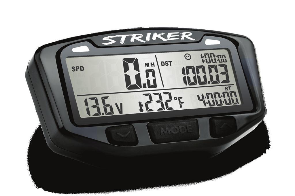
18 User Interface Normal Mode: All of the information that Striker provides is on one of these 3 screens. When riding, the user has the choice of staying on Screen 1 or Screen 2. Screen 3 contains statistical information and reverts back to screen 1 after a short period. TO SWITCH BETWEEN SCREENS, PRESS THE CENTER BUTTON (or the middle button on the remote.) or Screen 1: Speed (pg.21) Trip Distance (pg.22) Clock (pg.26) Voltage (pg.24) Engine Temp (pg.25) Ride Time (pg.27) 18
19 User Interface Screen 2: Speed (pg.21) Trip Distance (pg.22) Clock (pg.26) Voltage (pg.24) Air Temp (pg.25) Stop Watch (TT) (pg.26) Average speed may be set up to display on screen 2 rather than on screen 3 (pg.38). Screen 3: Avg Speed (pg.21) Max Speed (pg.21) Odometer (pg.22) Clock (pg.26) Accum. Ride Time (pg.27) Max Voltage (pg.24) Min Voltage (pg.24) Max Engine Temp (pg.25) Striker alternately displays min/max voltage and avg/max speed every 2 seconds. 19
20 System Features Overview: System Modes: Normal Mode is displayed during regular use. (pg.18-19) Sleep Mode displays only the clock after inactivity. (pg.20) Setup Mode edits system options. (pg.31-38) Trip Distance Edit Mode edits the distance (DST) value. (pg.23) Trip Data Reset resets temporary values to 0. (pg.30) Available Data: Speedometer (Speed, Average Speed, Maximum Speed) Voltage (Voltage, Maximum Voltage, Minimum Voltage) Distance (Odometer, Adjustable Trip Distance) Clock (Time of Day, Ride Time, Stop Watch, Accumulated Ride Time) Temperature (Ambient Air and Engine) Sleep Mode: If Striker sees no activity (either wheel movement or a button press) for 5 minutes, it will enter sleep mode and only display the clock. Sleep mode will end when any activity is noticed. 20
21 System Features Speedometer: Description: The speedometer function provides a display of current, average and max speed. Vehicle speed is calculated from the wheel sensor and user-entered wheel circumference. Speed: Displayed on screen 1 accompanied by a lit SPD icon. Average Speed: Displayed on screen 3 with a lit AVG SPD icon. AVG SPD is reset during a trip data reset. Maximum Speed: Displayed on screen 3 with a lit MAX SPD icon. Max speed is reset during a trip data reset. SPD on Screen 1 AVG SPD on Screen 3 MAX SPD on Screen 3 By default, Striker alternately displays avg speed and max speed every 2 seconds on screen 3. Average speed can move to screen 2 using setup mode. If done, average speed will move to screen 2 and replace the current speed. (pg.38) 21
22 System Features Distance: Description: The distance function provides a display of current trip distance and a permanent odometer. Distance is calculated from the wheel sensor and user-entered wheel size. (pg.16) Trip Distance: Displayed on screens 1 and 2 in the upper right with a lit DST icon. DST is reset during a trip data reset. Odometer: Displayed on screen 3 in the upper left with a lit ODO icon. ODO is NOT resettable. ODO has a resolution of 0.1 from , then shifts to a resolution of 1 from ,999. DST on Screen 1 ODO on Screen 3 PERFORM A TRIP DATA RESET BY HOLDING THE LEFT AND CENTER BUTTONS FOR 3 SECONDS. (pg.30) Striker can display tenths (0.0) or hundredths (0.00) decimal places for distance and odometer. (pg.38) 22
23 System Features Trip Distance Edit Mode: Description: The trip distance meter shows how much distance has been traveled since the last reset. Trip distance can be incremented manually using trip distance edit mode. Modifying trip distance is useful for synchronizing computers in the field for use in racing and technical comparisons. Adjust Trip Distance: When in trip distance edit mode, Striker displays only trip distance and the DST icon. Use the buttons to modify the DST value. ENTER OR EXIT TRIP DISTANCE EDIT MODE BY HOLDING THE CENTER BUTTON FOR 3 SECONDS. SCROLL DISTANCE VALUE BY PRESSING THE RIGHT OR LEFT BUTTONS. Hold to scroll faster. or Striker will return to normal mode after 5 seconds of inactivity. Striker can display tenths (0.0) or hundredths (0.00) decimal places during trip distance edit mode. (pg.38) 23
24 System Features Voltage: Description: The voltage function provides a display of voltage, maximum voltage, and minimum voltage. Voltage data is measured from the power input wire. It has a resolution of 0.1 volts and is accurate across the entire sensor range. Voltage: Displayed on screens 1 and 2 in the lower left with a lit V icon. Displays 0.0V if not connected to vehicle power. Displays HI if voltages exceeds the maximum specification (52.6V.) Voltage on Screen 1 Max/Min Voltage: Displayed on screen 3 in the lower left. Exceeding 52.6 Volts Min/Max voltage alternates being displayed every second, accompanied by V and the respective MIN/MAX icon. Min/Max Voltage on Screen 3 Voltage LEDs: The LEDs will flash if the voltage falls below the values defined by the user in setup mode, alerting of potential electrical system problems. See data setup mode for more information. (pg.36) 24
25 System Features Temperature: Description: The temperature function includes engine temperature, ambient temperature, and maximum engine temperature. The LEDs can alert of over-temp issues. Engine Temperature: Displayed on screen 1 in the lower middle with a thermometer icon. Ambient Temperature: Displayed on screen 2 with the AIR icon. Engine Temperature on Screen 1 Max Engine Temperature: Displayed on screen 3 with the MAX icon. Ambient Temperature on Screen 2 Temperature LEDs: The LEDs will turn on solid if the temperature exceeds the values defined by the user in setup mode, alerting of potential over-temp motor issues. (pg.35) 25
26 System Features Time: Description: The time features consist of a clock, current ride timer, accumulated run time, and stop watch (TT.) Clock: Displayed in the upper right on all screens, the clock increments continuously and has a selectable 12H or 24H H:M:S display. Time-of-Day Clock on All Screens Stop Watch (TT): Displayed on screen 2 in the lower right corner. The clock icon flashes while the stop watch is running. The stop watch is reset during a trip data reset. Stop Watch on Screen 2 START OR PAUSE THE STOP WATCH BY PRESSING THE LEFT BUTTON ON ANY SCREEN. TO RESET THE STOP WATCH, PERFORM A TRIP DATA RESET BY HOLDING THE LEFT AND CENTER BUTTONS FOR 3 SECONDS. (pg.30) 26
27 System Features Ride Time: Displayed in the bottom right corner of screen 1. Ride time shows how long the bike has been rolling since the last trip data reset. Ride time only increments when the vehicle is in motion. Ride Time on Screen 1 TO RESET THE RIDE TIME, PERFORM A TRIP DATA RESET BY HOLDING THE LEFT AND CENTER BUTTONS. (pg.30) Accumulated Ride Time: Similar to the odometer, accumulated ride time (ART) is not user resettable. Displayed in the bottom right corner of screen 3. ART tracks the total amount of time the vehicle has been in motion. Accumulated Ride Time on Screen 3 After 99 hours, ART rolls from H:M:S display to H:M up to 9999 hours. ART does not roll over to 0 when the max value is reached. 27
28 System Features Maintenance Icons: Description: There are two maintenance icons: OIL CAN and WRENCH. They alert of upcoming maintenance intervals. There is also a LO-BATTERY indicator to alert of low internal battery life. Maintenance Icons: Set a value in setup mode for each icon. Striker will countdown the miles, then display the icon. (pg.37) Lo Battery: The Lo-Battery icon is activated when the internal battery needs to be replaced. (Below 2.45V.) Wrench, Oil and Lo Battery Icons Things that will NOT reset the maintenance reminders: 1. Entering data setup mode. 2. Using the adjustable trip distance feature. 3. Resetting single-ride data. 4. Pressing the reset button on the back of Striker. When maintenance reminder setting screens are viewed in data setup mode, the icons will clear if they have been activated. (pg.37) 28
29 System Features Backlight: Description: Striker is equipped with a quality LED backlight for night-time operation. Connected to Vehicle Power: The backlight will turn off and Striker will enter sleep mode after 5 minutes of inactivity (any button press or wheel movement.) Internal Battery Only: The backlight must be activated by pressing the RIGHT button, will only remain lit for 3 seconds, and will light dimly to conserve internal battery power. If the LO-BATTERY icon is lit, the backlight will not turn on. Sleep mode will be entered after 5 minutes of inactivity. TO ACTIVATE THE BACKLIGHT MANUALLY, PRESS 29
30 Data Reset Data Reset: Description: After every ride, a trip data reset should be performed. The data will be reset to zero so that new information can be logged on the next ride. Values reset during a Data Reset: Avg Speed (pg.21) Max Speed (pg.21) Trip Distance (pg.22) Stop Watch (TT) (pg.26) Ride Time (pg.27) Max Voltage (pg.24) Min Voltage (pg.24) Max Engine Temp (pg.25) PERFORM A TRIP DATA RESET BY HOLDING THE LEFT AND CENTER BUTTONS FOR 3 SECONDS. Notes: The reset can be done from any screen. Accumulated Ride Time (ART) and Odometer (ODO) cannot be reset and are intended to maintain cumulative information. 30
31 Setup Mode Overview: Description: Setup mode is crucial for Striker to operate correctly. SETTINGS ORDER A. Distance Units B. Tire Size C. Clock D. Temperature E. LED Alerts F. Maintenance G. AVG SPD H. Distance VALUE KM/H or M/H Millimeters 12Hr or 24Hr Time-of-Day ºF or ºC Temperature High Alert Temperature Danger Alert Voltage Low Alert Voltage Danger Alert Oil Countdown Care Countdown Screen 2 or 3 Resolution DEFAULT M/H 2109mm 12Hr 12:00:00 ºF 000º 000º 0V 0V 0000 M/H 0000 M/H Screen 3 Res 2 Enter Setup Mode: HOLD DOWN ALL THREE BUTTONS FOR 3 SECONDS. All segments on the screen will turn black. Release to continue. 31
32 Setup Mode Setup Distance Units: Striker defaults to M/H. TO CYCLE BETWEEN M/H AND KM/H, PRESS THE LEFT BUTTON. TO CONFIRM, PRESS THE CENTER BUTTON. Striker will move on to the next setting. Setup Wheel Size: See Measure Wheel Size on page 16 for more information. DEFAULT ATV: MOTORCYCLE: 1675mm 2110mm MODIFY DIGIT: LEFT BUTTON NEXT DIGIT: RIGHT BUTTON TO CONFIRM, PRESS THE CENTER BUTTON. Striker will move on to the next setting. or 32
33 Setup Mode Setup Clock Format: Striker defaults to 12 Hr format. TO CYCLE BETWEEN A 12 HR OR 24 HR CLOCK, PRESS THE LEFT BUTTON. TO CONFIRM, PRESS THE CENTER BUTTON. Striker will move on to the next setting. Setup Time of Day: MODIFY DIGIT: LEFT BUTTON NEXT DIGIT: RIGHT BUTTON TO CONFIRM, PRESS THE CENTER BUTTON. Striker will move on to the next setting. or 33
34 Setup Mode Setup Temperature Units: Striker defaults to fahrenheit. TO CYCLE BETWEEN ºF and ºC, PRESS THE LEFT BUTTON. TO CONFIRM, PRESS THE CENTER BUTTON. Striker will move on to the next setting. The next two sections detail the over-temperature and undervoltage alert LEDs. The temperature alert will light up the LEDs solid-on, while the voltage alerts cause the LEDs to flash. Because a high engine temperature alert is a serious issue, it will override the voltage alert, should they happen to activate simultaneously. Striker must connect to vehicle power for LEDs to function. 34
35 Setup Mode Setup High Temperature LED: If engine temperature reaches this setting, the yellow LED will turn on as a caution. 0º (default) disables this alert. MODIFY DIGIT: LEFT BUTTON NEXT DIGIT: RIGHT BUTTON TO CONFIRM, PRESS THE CENTER BUTTON. Striker will move on to the next setting. or Setup Danger Temperature LED: If engine temperature reaches this setting, the red LED will turn on as a critical warning. 0º (default) disables this alert. MODIFY DIGIT: LEFT BUTTON NEXT DIGIT: RIGHT BUTTON TO CONFIRM, PRESS THE CENTER BUTTON. Striker will move on to the next setting. or 35
36 Setup Mode Setup Low Voltage LED: If voltage falls below this setting, the yellow LED will flash on as a caution. 0V (default) disables this alert. MODIFY DIGIT: LEFT BUTTON NEXT DIGIT: RIGHT BUTTON TO CONFIRM, PRESS THE CENTER BUTTON. Striker will move on to the next setting. or Setup Danger Voltage LED: If voltage falls below this setting, the red LED will flash as a critical warning. 0V (default) disables this alert. MODIFY DIGIT: LEFT BUTTON NEXT DIGIT: RIGHT BUTTON TO CONFIRM, PRESS THE CENTER BUTTON. Striker will move on to the next setting. or 36
37 Setup Mode Setup Oil and Wrench Alerts: Set the number of kilometers or miles left until Striker displays the oil and wrench reminder icons. After setting <OIL>, the <CARE> setting will appear. 0 KM/H or M/H (default) disables these alerts. Each km/mile travelled lowers the reminder values by 1. When the countdown reaches 0, the respective icon will activate. Striker will not reset these values automatically; they must be manually increased in setup mode. When these screens are viewed in setup mode, the icons will clear if they have been activated by reaching their countdowns. NOT affected by: Entering setup mode. Using the adjustable trip distance feature. Resetting single-ride data. A system reset. MODIFY DIGIT: LEFT BUTTON NEXT DIGIT: RIGHT BUTTON TO CONFIRM, PRESS THE CENTER BUTTON. Striker will move on to the next setting. or 37
38 Setup Mode Setup Average Speed s Screen: Choose screen for AVG SPD (default 3.) If screen 3, then AVG SPD and MAX SPD rotate every 2 seconds. If screen 2, AVG SPD replaces SPD. MODIFY DIGIT: LEFT BUTTON NEXT DIGIT: RIGHT BUTTON TO CONFIRM, PRESS THE CENTER BUTTON. Striker will move on to the next setting. or Setup Distance Resolution: Choose if Striker should display one (0.0) or two (0.00) decimal places for distance and odometer. TO CYCLE BETWEEN ONE (0.0) and TWO (0.00) DECIMALS, PRESS LEFT BUTTON. TO CONFIRM, PRESS THE CENTER BUTTON. Striker will return to normal mode. 38
39 Notes Notes: 39
40 FAQ Troubleshooting Frequently Asked Questions: Why does nothing work? Try the reset button on the back of Striker. The internal battery may be dead, or Striker is not hooked up to vehicle power properly. Review installation procedure. What kind of electrical systems does Striker work with? The voltage readout works on systems with any type of battery (lead acid, NiMH, NiCad, Li-Ion, etc.) Striker works best on vehicles with DC electrical systems (where a battery or capacitor is installed.) The voltage readout will be accurate and comparable to quality multi-meters. Striker will operate on AC electrical systems but displays voltage with less accuracy. (Not a true RMS meter.) Striker operates with a 4-point floating voltage average. Everything is working, but the (K)MPH reading is way off. The speed sensor/magnet may be installed incorrectly. Double check installation. See page The wheel size setting may be incorrect. Please review wheel size measurement instructions in this manual. See page
41 FAQ Troubleshooting The screen is hazy or crazed. Did gasoline, degreasers, or other chemical cleaners come in contact with Striker s screen? Chemicals can damage Striker. The backlight won t stay lit. Striker needs to be connected to vehicle s 12 volt system in order for the backlight to be continuous on. Review installation procedure. See page 9 and 29. Striker s internal battery is dead. To replace the battery, use a coin to unscrew the round panel on the back of Striker. Remove the old battery and install the new one. Make sure the positive pole is facing up. Replace with common watch battery CR2302. See page 10. Why aren t the LEDs working? Striker needs to be connected to the vehicle battery in order for the LEDs to function. Settings must be programmed manually. See pages The LEDs dim or go out if the vehicle battery voltage is too low. The maintenance icons won t clear off the screen. Go into setup mode and make sure OIL and CARE are both set to 0. The icons should then disappear from the normal screens. See page
42 Glossary ACCUMULATED RIDE TIME (ART): The long-term total amount of time spent riding (all ride times added together.) ART cannot be reset. ADJUSTABLE DISTANCE EDIT: Special mode to edit the distance traveled since the last data reset. Page 23. AVERAGE SPEED (AVG SPD): The mean (average) speed the vehicle has been traveling since the last data reset. BACKLIGHT: The light that brightens up Striker s display. (TRIP) DISTANCE (DST): The distance covered since the last data reset. LEDs: The LEDs at the top of Striker can be programmed to alert of problems with voltage or temperature. MAINTENANCE REMINDERS ( ): The user programmable countdown in miles or kilometers for oil and wrench reminder icons. MAXIMUM SPEED (MAX SPD): The fastest speed achieved since the last data reset. 42
43 Glossary ODOMETER (ODO): The total accumulated distance Striker has traveled. The odometer is permanent and cannot be reset. REMOTE SWITCH: Optional remote control that mounts to handlebar next to the hand. The remote s buttons duplicate the buttons on the main computer, but make them easier to reach. RIDE TIME (RT): The amount of time the wheels have been rolling since the last data reset. SENSORS: The speed sensor works with the magnet to let Striker collect its wheel data; a second sensor measures the temperature. SLEEP MODE: If Striker doesn t receive any sensory information it will go into Sleep Mode and only display the clock. SPEED (SPD): The vehicle s current speed. STOP WATCH (TT): This is a short term, regular stop watch. VOLTAGE (V): The condition of the vehicle s battery and electrical system. WHEEL SIZE: Very important. Used to determine speed and distance. Refer to the measurement section. Page
44 LIMITED WARRANTY Within one year from the date of original purchase, Trail Tech will repair or replace, at its option, any Trail Tech powersport computer which is deemed defective in workmanship or materials. Please contact Trail Tech or the dealer where the item was purchased for assistance. Damage or injuries resulting from negligence or misuse are not covered by this warranty. Incidental or consequential damages are specifically excluded.* This warranty gives you specific legal rights. You may also have other rights which vary from state to state. *Because some states do not allow the exclusion of incidental or consequential damages, this exclusion may not apply to you. Trail Tech and Striker are trademarks of Trail Tech, Inc. Tech Support: (844)
Table of Contents. Page # Table of Contents. 2 Precautions 3 SPECIFICATIONS. 4 Overview. 6 Installation. 9 Measure Wheel Size. 14 Data Setting Mode
 Table of Contents Page # Table of Contents 1 A Note To You 2 Precautions 3 SPECIFICATIONS 4 Overview 6 Installation 9 Measure Wheel Size 14 Data Setting Mode 16 Normal Mode Screens 28 VAPOR FEATURES 30
MOTORSPORT COMPUTER USER S MANUAL
 MOTORSPORT COMPUTER USER S MANUAL A PRODUCT Table of Contents PAGE # TABLE OF CONTENTS 1 A NOTE TO YOU 2 PRECAUTIONS 3 SPECIFICATIONS 4 PARTS & FEATURES 6 INSTALLATION 10 MEASURE WHEEL SIZE 16 DATA SETTING
Owner s Manual. Made in USA
 Owner s Manual Made in USA www.icoracing.com 2 Installation Connect to 12V Battery Avoid routing the wires directly against the ignition coil and spark plug wiring. Your Rallye MAX is designed to use 12V
Trip 2, 2L, 3 and 5W Owner s Manual. ENGLISH
 Trip 2, 2L, 3 and 5W Owner s Manual. ENGLISH WELCOME. Thank you for buying a Bontrager Trip computer. We hope this computer gives you miles (or kilometers) of pleasure. Your Trip computer may not include
ENGLISH CONTENTS 1. INTRODUCTION 2. WARNINGS & CAUTIONS 3. V100 ILLUSTRATIONS 4. BUTTON FUNCTIONS
 ENGLISH CONTENTS 1. INTRODUCTION 2. WARNINGS & CAUTIONS 3. V100 ILLUSTRATIONS HEAD UNIT COMPONENT ILLUSTRATIONS 4. BUTTON FUNCTIONS SETUP MODE OPERATING MODE 5. V100 SCREEN DISPLAY SEQUENCE: BI-LEVEL MEMORY
Trip 1 & Trip 4W Owner s Manual. ENGLISH
 Trip 1 & Trip 4W Owner s Manual. ENGLISH WELCOME. Thank you for buying a Bontrager Trip computer. We hope this computer gives you miles (or kilometers) of pleasure. Your Trip computer may not include all
CYCLE COMPUTER OWNER'S MANUAL ENGLISH FRANÇAIS ESPANOL DEUTSCH ITALIANO
 CYCLE COMPUTER OWNER'S MANUAL ENGLISH FRANÇAIS ESPANOL DEUTSCH ITALIANO INTRODUCTION Congratulations on your purchase of the new Vetta C-06 cycle computer. The C-06 is designed to be the simplest, smallest
UTV-1200 Multi Gauge for 2008 Yamaha Rhino
 IMPORTANT NOTE! This gauge has an hour meter and odometer preset option available only for the first 1.0 engine hour and 10 miles (16km). See ODO/HR PRESET for instructions. UTV-1200 Multi Gauge for 2008
EX-RAY LIMITED WARRANTY
 EX-RAY LIMITED WARRANTY Within 1 year from the date of purchase, Alltrax Inc., Will repair or replace, at it s option, and EX-RAY which is deemed defective in workmanship or materials. EX-RAY VOLTAGE Digital
Driver s Display. ALFA-Elite & ALFA-Pro. Owners Manual. Rev 1.2, July (Preliminary) (September 21, 2012) Small Systems Specialists
 (September 21, 2012) Small Systems Specialists") Driver s Display ALFA-Elite & ALFA-Pro Owners Manual Rev 1.2, July 2010 (Preliminary) (September 21, 2012) Small Systems Specialists P.O. Box 310 Windsor, NJ 08561 Phone 609-301-0541 Email ALFA@Rally.cc
Driver s Display ALFA-Elite & ALFA-Pro Owners Manual Rev 1.2, July 2010 (Preliminary) (September 21, 2012) Small Systems Specialists P.O. Box 310 Windsor, NJ 08561 Phone 609-301-0541 Email ALFA@Rally.cc
UTV-1000 Multi Gauge for Yamaha Rhino
 IMPORTANT NOTE! This gauge has an hour meter and odometer preset option available only for the first 1.0 engine hour and 10 miles (16km). See ODO/HR PRESET for instructions. UTV-1000 Multi Gauge for 2004-2006
CATEYE STRADA SLIM CYCLOCOMPUTER CC-RD310W
 CC-RD310W ENG 1 CATEYE STRADA SLIM CYCLOCOMPUTER CC-RD310W This model comes with a sensor inspired by modern road bikes. It may not be used for bikes with a large space between the front fork and spoke.
MODEL MCL /8 SPEEDOMETER/TACHOMETER for 2004 up
 MODEL MCL-3204 3-3/8 SPEEDOMETER/TACHOMETER for 2004 up IMPORTANT NOTE! This gauge has an odometer preset option that is only available one time in the first 100 miles (160km) of operation. See Odometer
Attention! 1 Accessories. 2-1 Installation description ❹ ❺. Please proceed as follows
 Thank you for purchasing the TNT-B meter for Yamaha Bolt. Before installing, please read the instruction carefully and keep it for future reference. Attention! For installation, please follow the steps
CATEYE URBAN WIRELESS+
 CATEYE URBAN WIRELESS+ CYCLOCOMPUTER CC-VT5W Mounting the computer Setting up the computer Starting measurement This instruction manual is subject to change without notice. See our website for the latest
MODEL MCL-3212 SPEEDOMETER/TACHOMETER for 2012 up Dyna and Softail with 4 gauge
 MODEL MCL-3212 SPEEDOMETER/TACHOMETER for 2012 up Dyna and Softail with 4 gauge IMPORTANT NOTE! This gauge has an odometer preset option that is only available one time in the first 100 miles (160km) of
MODEL MVX-2011 TANK MOUNT SPEEDOMETER/TACHOMETER
 MODEL MVX-2011 TANK MOUNT SPEEDOMETER/TACHOMETER Wiring Diagram The MVX-2011 gauges will work on 2011-up Softail models with 5 gauges or 2012-up Dyna models with 5 gauges. It is a direct plug in on these
GB C10WL. English page 1-18 D C10WL F C10WL I C10WL E C10WL NL C10WL. Deutsch Seite Français page Italiano pagine 57-74
 English page 1-18 Deutsch Seite 19-38 Français page 39-56 Italiano pagine 57-74 Español pagina 75-92 Nederlands pagina 93-1 D F I E NL ETRTO WS in mm KMH WS in inch MPH 47-305 16x1,75 1272 50,1 47-406
Rallye VR Light. MADE IN USA
 Rallye VR Light MADE IN USA www.icoracing.com Contents Introduction Overview of operation New Functions Button Symbols Page 11 2 Setup functions Functions in a race Edit Set wheel circumference Show clock/hide
CATEYE VELO WIRELESS CYCLOCOMPUTER CC-VT230W. Mounting the. computer. Setting up the. computer. Starting measurement.
 CATEYE VELO WIRELESS CYCLOCOMPUTER CC-VT0W Mounting the computer Setting up the computer Starting measurement This instruction manual is subject to change without notice. See our website for the latest
MCL-30K-SPD IMPORTANT NOTE!
 MCL-30K-SPD Thank you for purchasing the Dakota Digital MCL-30K-SPD gauge for your Harley Davidson Touring bike. This is designed to be a replacement for all touring models from 1996 2003. This is part
MCL-3014 gauge kit. Optional Readings: Boost Pressure with MBM-09, Front or Rear Air Suspension Pressure with MBM-19
 MCL-3014 gauge kit Thank you for purchasing the Dakota Digital MCL gauge kit for your Harley Davidson Touring bike. This kit is designed to be a direct plug in replacement for all touring models from 2014
REMOVAL OF FACTORY GAUGE ULTRA FLHT & FLHX (STREET GLIDE
 MCL-36K-SPD Thank you for purchasing the Dakota Digital MCL-36K-SPD gauge for your Harley Davidson Touring bike. This kit is designed to be a direct, plug in replacement for all touring models from 2004
Garden Thermometer with Solar Lighting
 Garden Thermometer with Solar Lighting Model 306-645 FEATURES Clear Functional Design Large digital Display with 2 Diff Modes Maximum and Minimum Clock Automatic Backlight Solar Panel with 180 Degree Rotation
Wireless Tire Pressure and Temperature Monitoring System Instruction Manual Model #: TM Cap Sensors
 Wireless Tire Pressure and Temperature Monitoring System Instruction Manual Model #: TM-510 510 Cap Sensors Thank you for purchasing the TST Tire Pressure Monitoring System. With minimal care, your new
ALFA-Club. Owners Manual Rev 4.0, August Small Systems Specialists 201 N. Lobb Ave. Pen Argyl, PA Memory Checkpoint Clock
 ALFA-Club Memory Checkpoint Clock Dual Odometer/Clock Owners Manual Rev 4.0, August 2018 Small Systems Specialists 201 N. Lobb Ave. Pen Argyl, PA 18072 609-301-0541 ALFA@Rally.cc On the web at www.rally.cc
TALON 22 WHEEL & TALON X-TREME 38 WHEEL TPMS, UP to 188 PSI PRESSURE AND TEMPERATURE WITH CAP OR FEEDTHRU SENSORS
 TALON 22 WHEEL & TALON X-TREME 38 WHEEL TPMS, UP to 188 PSI PRESSURE AND TEMPERATURE WITH CAP OR FEEDTHRU SENSORS Thank you for your purchase of The HawksHead TALON OR TALON X-TREME TPMS System With ease
Information displays GENERAL INFORMATION A : 238.7
 Information displays GENERAL INFORMATION The message center display panel is situated within the instrument cluster, between the tachometer and speedometer gauges. The message center is active as soon
PN# A,13-316A,13-317A, , , & TireGard
 PN# 13-315A,13-316A,13-317A, 13-325, 13-326, & 13-327 TireGard Wireless Tire Pressure Monitoring System Table of Contents Precautions 2 TireGard Features and Benefits 2 Controls 3 LCD Receiver/Monitor
MODEL MCL-2004(-R) TANK MOUNT SPEEDOMETER/TACHOMETER
 TANK MOUNT SPEEDOMETER/TACHOMETER") MODEL MCL-2004(-R) TANK MOUNT SPEEDOMETER/TACHOMETER Wiring Diagram The MCL-2004(-R) gauges will work on 2004-2011 models except 2011 Softail. It is a direct plug in on these models and requires no additional
MODEL MCL-2004(-R) TANK MOUNT SPEEDOMETER/TACHOMETER Wiring Diagram The MCL-2004(-R) gauges will work on 2004-2011 models except 2011 Softail. It is a direct plug in on these models and requires no additional
DAFM4. Digital Air Flow Meter INSTRUCTION MANUAL Fax: (503) ENGLISH DAFM4 VOL CFM
 ENGLISH DAFM4 VOL CFM") Digital Air Flow Meter INSTRUCTION MANUAL ENGLISH DAFM4 DAFM4 VOL CFM LW MODE HOLD START STOP EXIT LW-D-AREA MAX / MIN [HOLD TO EXIT AVG AVG MODE] ON / OFF (SET) 1-800-547-5740 Fax: (503) 643-6322 www.ueitest.com
Digital Air Flow Meter INSTRUCTION MANUAL ENGLISH DAFM4 DAFM4 VOL CFM LW MODE HOLD START STOP EXIT LW-D-AREA MAX / MIN [HOLD TO EXIT AVG AVG MODE] ON / OFF (SET) 1-800-547-5740 Fax: (503) 643-6322 www.ueitest.com
MODEL MCL-2002 TANK MOUNT SPEEDOMETER/TACHOMETER
 MODEL MCL-2002 TANK MOUNT SPEEDOMETER/TACHOMETER *To avoid damage to motorcycle, please see Speedometer, Tachometer, and Status and Warning Indicators sections for details on locating VSS, Tachometer,
REMOVAL OF FACTORY GAUGES ULTRA FLHT & FLHX
 MVX-8X04 gauge kit Thank you for purchasing the Dakota Digital MVX gauge kit for your Harley Davidson Touring bike. This kit is designed to be a direct plug in replacement for all touring models from 2004
Mid-Drive Electric Bicycle Kit EVBIKE-SET-CMS-48 EVBIKE-SET-CMS-36
 INSTALLATION MANUAL Mid-Drive Electric Bicycle Kit EVBIKE-SET-CMS-48 EVBIKE-SET-CMS-36 Thank you for purchasing EVBIKE product and we hope that you will become a happy user. Carefully read the entire manual
Quick Guide. Unipro Laptimer Version September Go faster faster. UNIPRO ApS
 Quick Guide Unipro Laptimer 6003 Version 1.45 5. September 2009 Go faster faster UNIPRO ApS VIBORG HOVEDVEJ 24 DK-7100 VEJLE DENMARK Tel.: +45 75 85 11 82 Fax: +45 75 85 17 82 www.uniprolaptimer.com mail@uniprolaptimer.com
SL150 Digital Speed Log Owner s Manual
 SL150 Digital Speed Log Owner s Manual Marine Division of Vertex Standard LIMITED WARRANTY STANDARD HORIZON MARINE DIVISION OF VERTEX STANDARD warrants to the original purchaser that each new Marine Product
2007 Mercury Marine SmartCraft Gauges
 i 27 Mercury Marine SmartCraft Gauges 9-89828315 97 ii TABLE OF CONTENTS System Tachometer/Speedometer Basic Operation and Features...1 Automatic Engine Detection Feature...1 Master Reset...2 Alarm Warnings...3
Components. Options Accessory Harness USB Charger. Quick Connector. Hook & Loop / Cable-ties. RFID Antenna. Module. Main Harness.
 SRX SERIES Table of Contents - Components - Planning The Install - Mounting - Switched Power - Attach Accessory Harness - Plug In Module - Back-Up Battery - Remote Encoding - 2-Way RFID Remote User Instructions
Contents. Introduction Features... 1 About AutoCal... 2 Installing Batteries... 4 Button Logic... 5 Messages Programming
 Contents Introduction Features... 1 About AutoCal... 2 Installing Batteries... 4 Button Logic... 5 Messages... 6 Programming Running Miscellaneous ChEc Wheel Size... 8 Adjust Wheel Size... 9 LoAd Resets...
Caution! Some procedures must be followed in order to avoid damages from occuring to the vehicle.
 Thank you for purchasing KOSO's TNT-04 meter. Please read the instructions carefully and retain them for future reference. Notice To avoid a short circuit from occuring do not pull or modify the wires
TIMER INTERFACE USER MANUAL
 TIMER INTERFACE USER MANUAL Premium Efficiency Two-Speed Motor with Integrated Timer Formerly A. O. Smith Electrical Products Company A Regal Beloit Company COPYRIGHT Copyright 2011, Regal Beloit EPC,
Owner s Manual. Rallye CAP. Made in USA.
 Owner s Manual Rallye CAP Made in USA www.icoracing.com 2 Foreward Dear Rally Competitor, Thank you for purchasing the ICO Racing Rallye CAP instrument. We hope you enjoy this new ICO Racing product. For
Quick Guide. Unipro Laptimer Version Go faster faster. UNIPRO ApS
 Quick Guide Unipro Laptimer 5004 Version 1.32 Go faster faster UNIPRO ApS VIBORG HOVEDVEJ 24 DK-7100 VEJLE DENMARK Tel.: +45 75 85 11 82 Fax: +45 75 85 17 82 www.uniprolaptimer.com mail@uniprolaptimer.com
Digatron s DT-46K Instruction Manual
 Digatron s DT-46K Instruction Manual PLAY PAUSE MAX EVENT FUNCTION POWER EXIT Introduction Congratulations on the purchase of your new DT-46K. The DT-46K is Digatron s small, easy to use, multi-function,
User Manual Solar Charge Controller 3KW
 User Manual Solar Charge Controller 3KW Version: 1.3 CONTENTS 1 ABOUT THIS MANUAL... 1 1.1 Purpose... 1 1.2 Scope... 1 1.3 SAFETY INSTRUCTIONS... 1 2 INTRODUCTION... 2 2.1 Features... 2 2.2 Product Overview...
USER MANUAL EN IN 902 Wireless Cycle Computer insportline CY-200W
 USER MANUAL EN IN 902 Wireless Cycle Computer insportline CY-200W 1 CONTENTS ITRODUCTION... 3 MAIN ITEM LIST... 4 DISPLAY... 5 HOW TO SETUP CYCLE COMPUTER... 6 WHEEL CIRCUMFERENCE... 6 INSTALLING THE BRACKET...
KOSO RX1N / PGO Gauge Cluster
 KOSO RX1N / PGO Gauge Cluster Thank you for the purchase of this wonderful gauge! Here is some background information about the PGO gauge. When manufactured by Koso, it was called the RX1N. Recently, Koso
Wireless Tire Pressure and Temperature Monitoring System Instruction Manual Model #: TM-507 SCE 507 Commercial Cap Sensors with Monochrome Display
 Wireless Tire Pressure and Temperature Monitoring System Instruction Manual Model #: TM-507 SCE 507 Commercial Cap Sensors with Monochrome Display Thank you for purchasing the TST Tire Pressure Monitoring
Volkswagen Information System. Introduction
 Volkswagen Information System Introduction In this section you ll find information about: Using the instrument cluster menus: Basic version Using the instrument cluster menus: Premium version with multi-function
MCL-30K-TCH. Remove nuts/screws and clamp to remove factory gauges 1 MAN#650336
 MCL-30K-TCH Thank you for purchasing the Dakota Digital MCL-30K-TCH gauge for your Harley Davidson Touring bike. This kit is designed to be a replacement for all touring models, from 1996 2003. This is
TABLE OF CONTENTS. chargex - Onboard charger chargex mini Charger with EL display
 TABLE OF CONTENTS CG-25 chargeguard Monitoring System 2 CX-10 CXM-20 chargex - Onboard charger chargex mini Charger with EL display 3 CGF-10 CGS-10 CGM-10 CX-10 CXM-20 chargeguard Multi-function Display
Gauge installation The MLX-2011 is designed to fit in the Fat Bob style five-inch diameter dash mount gauge openings.
 MLX-2011 TANK MOUNT SPEEDOMETER/TACHOMETER 2011-newer Harley Davidson Softail, 2012-newer Dyna and 2014-newer Road King models Included parts: MBM harness 2x 8-32 x ½ screw 2x #8 lock washer 2x L-bracket
CATEYE MICRO Wireless
 CATEYE MICRO Wireless CYCLOCOMPUTER CC-MC200W Before using the computer, please thoroughly read this manual and keep it for future reference. Please visit our website, where detailed instructions with
Combined Ventilation Controller RVWS-T-224HA
 Combined Ventilation Controller RVWS-T-224HA 8-stage Control for Power/Natural Applications 2 variable speed stages, 2 curtain winch stages, 2 fixed speed ventilation stages, 1 thermo/mister cycle stage
G203V / G213V MANUAL STEP MOTOR DRIVE
 G203V / G213V MANUAL STEP MOTOR DRIVE PRODUCT DIMENSIONS PHYSICAL AND ELECTRICAL RATINGS Minimum Maximum Units Supply Voltage 18 80 VDC Motor Current 0 7 A Power Dissipation 1 13 W Short Circuit Trip 10
Instruction Manual. Duo-battery Solar Panel Controller EPIP20-DB series For Both 10 and 20 amp. Controllers (for use with solar panels only) + -
 + -") Instruction Manual Duo-battery Solar Panel Controller EPIP20-DB series For Both 10 and 20 amp. Controllers (for use with solar panels only) + - Optional - Switch to disconnect solar panel when engine alternator
Instruction Manual Duo-battery Solar Panel Controller EPIP20-DB series For Both 10 and 20 amp. Controllers (for use with solar panels only) + - Optional - Switch to disconnect solar panel when engine alternator
UNIVERSAL GAUGE WIRE HARNESS
 2650-1797-00 UNIVERSAL GAUGE WIRE HARNESS For Installing Auto Meter Electric Speedometer, Tachometer, And Short Sweep Electric Oil Pressure, Water Temperature, Fuel Level, and Volt Meter Gauges. This harness
IMPORTANT! DO NOT THROW AWAY THE SHIPPING CARTON AND PACKING MATERIAL
 Operator s Manual IMPORTANT! DO NOT THROW AWAY THE SHIPPING CARTON AND PACKING MATERIAL ii Table of Contents Operator Safety... 1 Introduction... 2 Unpacking and Setup... 3 Unpacking... 3 Setup... 4 ROCKET
MLX-8414 Direct plug in instrument system for 2014-up Harley Davidson Touring models
 The MLX-8414 kit includes: MLX-8414 Direct plug in instrument system for 2014-up Harley Davidson Touring models MLX displays Oil temperature sensor harness Cable ties Interconnect harness Oil temperature
Operations Manual. Zero Speed Switch Sensor Model ZS09P
 Zero Speed Switch Sensor Model ZS09P The must be referred to for correct installation. Failure to comply with the shall void all warranties and liabilities. Overview The Phares Electronics Model ZS09P
OPERATING MANUAL Digital Diesel Control Remote control panel for WhisperPower generator sets
 Art. nr. 40200261 OPERATING MANUAL Digital Diesel Control Remote control panel for WhisperPower generator sets WHISPERPOWER BV Kelvinlaan 82 9207 JB Drachten Netherlands Tel.: +31-512-571550 Fax.: +31-512-571599
CONTACT TACHOMETER User s ManUal CT6235B
 CONTACT TACHOMETER User s ManUal CT6235B Please read this manual carefully and thoroughly before using this product. TABLE OF CONTENTS Introduction......................... 3 Key Features........................
SPA MICROPROCESSOR COMBINED TACHO&SPEEDO/GAUGE INSTALLATION AND OPERATING MANUAL PAGE 2...INSTRUMENT FEATURES PAGE 3...OPERATING INSTRUCTIONS
 SPA MICROPROCESSOR COMBINED TACHO&SPEEDO/GAUGE INSTALLATION AND OPERATING MANUAL PAGE 2...INSTRUMENT FEATURES PAGE 3...OPERATING INSTRUCTIONS PAGE 3...MENU SYSTEM PAGE 9...INSTALLATION DIAGRAMS PAGE 13...INSTALLATION
Solar Dock Post Lites
 12 Lumens Solar Dock Post Lites 8X brigthter and longer lasting than solar garden lights! The Solar Dock Lite v5 is a great way to light up your dock or pier. During the day the solar panel collects the
User Manual. T6 Tachometer. Online: Telephone: P.O. Box St. Petersburg, Florida 33736
 User Manual T6 Tachometer Online: www.phareselectronics.com Telephone: 727-623-0894 P.O. Box 67251 St. Petersburg, Florida 33736 Table of Contents Overview... 1 Description... 1 Wiring... 1 T6 Tachometer
Intelli-Feed Controller User s Manual Intelli-Feed Digital Tachometer and Hourmeter
 Intelli-Feed Controller User s Manual Intelli-Feed Digital Tachometer and Hourmeter Part #: 9047 Table of Contents: Table of Contents 2 Intelli-Feed TM User Interface 3 Equipment Diagnostic Indicators
DAKOTA DIGITAL MVX-8K Series Analog Gauges
 tech DAKOTA DIGITAL Story by Brandt Wettestad Photos by Jesse B. Nelson I have found it difficult to find somebody who doesn t like Dakota Digital. Their technology with digital gauges is outstanding as
Digital Mobile Charge Advanced Electronic In-Transit 4-Stage Battery to Battery Charger
 Digital Mobile Charge Advanced Electronic In-Transit 4-Stage Battery to Battery Charger Owner s Manual and Installation Guide Model Part Number Description Digital Mobile Charge 05502 Advanced In-Transit
Information displays GENERAL INFORMATION A : 392.4
 Information displays GENERAL INFORMATION The driver message and information centre display panel is situated within the instrument panel, between the tachometer and speedometer gauges. The message and
Owner s Guide PROCOMP
 professional series Owner s Guide PROCOMP Deluxe Vehicle Security and Remote Start System with 900 Mhz 2 Way Confirming OLED Remote Control IMPORTANT NOTE: The operation of the Security and Convenience
MCL-3006 gauge kit IMPORTANT NOTE!
 MCL-3006 gauge kit Thank you for purchasing the Dakota Digital MCL-3006 gauge kit for your Harley Davidson Touring bike. This kit is designed to be a direct, plug in replacement for all touring models
MLX-8696/MLX-8496 Direct plug in instrument system for Harley Davidson Touring models
 MLX-8696/MLX-8496 Direct plug in instrument system for 1996-2003 Harley Davidson Touring models The MLX-8696 kit includes: MLX displays (MLX-8496 features two small gauges) Oil temperature sensor harness
Installation and Maintenance Instructions. World Leader in Modular Torque Limiters. PTM-4 Load Monitor
 World Leader in Modular Torque Limiters Installation and Maintenance Instructions PTM-4 Load Monitor 1304 Twin Oaks Street Wichita Falls, Texas 76302 (940) 723-7800 Fax: (940) 723-7888 E-mail: sales@brunelcorp.com
MLX-8604/MLX-8404 Direct plug in instrument system for Harley Davidson Touring models
 MLX-8604/MLX-8404 Direct plug in instrument system for 2004-2013 Harley Davidson Touring models The MLX-8604 kit includes: MLX displays (MLX-8404 features two small gauges) Oil temperature sensor harness
MODEL MCV-7000 series SPEEDOMETER/TACHOMETER INFORMATION GAUGE Please read this before beginning installation or wiring.
 MODEL MCV-7000 series SPEEDOMETER/TACHOMETER INFORMATION GAUGE Please read this before beginning installation or wiring. IMPORTANT NOTE! This gauge has an odometer preset option that is only available
USB Charge Port Installation Instructions
 USB Charge Port Installation Instructions Lifetime Technical Support support@logolites.com 770-476-7322 www.logolites.com Manual 100-0014C Thank you for purchasing a Logo Lites USB Charge Port! USB Charge
ECLIPSE Laundry Dispenser Controller
 ECLIPSE Laundry Dispenser Controller Reference Manual Programming and Operation Online and downloadable Product Manuals and Quick Start Guides are available at www.hydrosystemsco.com Please check online
COMBINATION SPEEDOMETER/TACHOMETER GAUGE KIT J
 COMBINATION SPEEDOMETER/TACHOMETER GAUGE KIT J05306 2015-04-24 GENERAL Figure 1. Title 49, United States Code GENERAL (Continued) Table 1. Speedometer Features Available MODELS FEATURES GEAR INDICATOR
DP10001 UNIVERSAL 5 GAUGE DIGITAL PANEL
 Nordskog Performance Products DP10001 UNIVERSAL 5 GAUGE DIGITAL PANEL **Before beginning the installation, read through these instructions thoroughly. Also, disconnect the positive battery cable to avoid
User Manual. MB-6000-UD Rev. 1.03
 User Manual MB-6000-UD Rev. 1.03 Table of Contents I. The Controls II. III. IV. Unit Operations A. Folding the Unit B. Folding the Handlebars C. Unlocking and Unfolding D. Precautions and Starting E. Power
Solar Differential Temperature Controller Model DTC-D
 OVERVIEW The DTC-D is specifically designed for solar heating applications where the collector circulation pump is powered from a solar (PV) panel, or optionally, battery power or any 12VDC source. Its
Active Controlled Cooling System
 Active Controlled Cooling System April 2011 3267 Progress Dr Orlando, FL 32826 www.apecor.com Preliminary www.apecor.com Table of Contents General Information... 3 Safety... 3 Introduction... 3 What s
Assembly & Usage Guide - IZIP E3Metro
 Assembly & Usage Guide - IZIP E3Metro This guide is intended to be followed by an experienced bicycle mechanic. If you have any doubts about your ability to safely assemble a bicycle, please let a professional
INSTRUCTIONS SPECIAL FEATURES
 INSTRUCTIONS Discharge Termination: auto-cut based on individual cell voltages 2.75V per cell in Quick-Balance Mode 3.0V per cell in Interface Mode with separate discharger Discharge Current: 120mA per
Manual Installation & Operation
 Manual Installation & Operation Model: NCxxLxx 12A or 30A Solid State Solar Charging Regulator and 12A Load Controller. 231 Patent #: 5,642,030 Applies Page 1 Warnings When Installing, connect grounds,
A Cheap Speedometer for Touring by Tony Cimorelli
 A Cheap Speedometer for Touring by Tony Cimorelli How many times have you been out touring and wanted to know the distance between point A and B? Maybe you want to know the distance that a tour takes or
USER MANUAL Raptor V G Digital Wireless System
 USER MANUAL Raptor V1.0 2.4G Digital Wireless System Thank you for choosing Shanren products We focus on developing intelligent professional cycling equipment This manual includes instructions for the
ELECTRIC FOLDING BIKE OWNERS MANUAL. e-power 36v. Go City-Lite
 P o w e r ELECTRIC FOLDING BIKE OWNERS MANUAL e-power 36v Go City-Lite Thank you for purchasing a Seago electric folding bike. In order to get the best out of your new bike you must read and fully understand
**Detailed instructions for balancing aluminum wheels in Section 15 of manual.
 PWB-1530 Manual Please read this Manual before using the Machine. You will need to know the safety instructions, System Settings, Wheel Parameters Input and Calibration process before you can properly
Bio Lion Table Top Centrifuge XC-H165
 Bio Lion Table Top Centrifuge XC-H165 Operation Manual Table of contents Section Specification Page 1 Pictures Page 2-3 Starting Safety information Page 4 Set up Page 5-7 Operation Page 7-8 Troubleshooting
Thermometer models / 00831A
 Instruction Manual Thermometer models 00822 / 00831A CONTENTS Unpacking Instructions... 2 Package Contents... 2 Product Registration... 2 Features & Benefits... 3 Setup... 4 Install or Replace Batteries...
Wireless Tire Pressure and Temperature Monitoring System Color Display Manual. Wide Screen Color Display Model #: TST-507-D-C
 Wireless Tire Pressure and Temperature Monitoring System Color Display Manual Wide Screen Color Display Model #: TST-507-D-C Thank you for purchasing the TST Tire Pressure Monitoring System. With minimal
rtable Electric Scooter USER MANUAL A new era in urban mobility PLEASE CAREFULLY READ THE USER MANUAL AND WARRANTY BOOK BEFORE USING!
 rtable Electric Scooter USER MANUAL A new era in urban mobility PLEASE CAREFULLY READ THE USER MANUAL AND WARRANTY BOOK BEFORE USING! The most economical vehicle in history User Manual Page 1 / 20 04/2017
TMD90A Dual Input Digital Thermometer
 TMD90A Dual Input Digital Thermometer User Manual For detailed specifications and ordering info go to www.testequipmentdepot.com TMD90A Dual Input Thermometer Contents Safety Information 2 Symbols Used
MODEL MCL-2002 TANK MOUNT SPEEDOMETER/TACHOMETER
 MODEL MCL-2002 TANK MOUNT SPEEDOMETER/TACHOMETER *To avoid damage to motorcycle, please see Speedometer, Tachometer, and Status and Warning Indicators sections for details on locating VSS, Tachometer,
Cruising Charger Series OWNER S MANUAL
 R Cruising Charger Series OWNER S MANUAL ON BOARD BATTERY CHARGERS Models DC Amperage No. Of Banks Volts 2614A 5,10 Amps 2 Bank 12/12 2614A-230 2621A 5,5,10 Amps 3 Banks 12/12/12 2621A-230 2622A 10,10
BAPI-Stat Quantum Temperature Sensor with Display and Slider Setpoint
 Product Identification and Overview The BAPI-Stat Quantum style room temperature sensor features a large format LCD and slider setpoint adjustment. Additional options include button override and communication
ELECTRIC BICYCLE OWNER S MANUAL
 ELECTRIC BICYCLE OWNER S MANUAL For Owners of EG Kyoto 350 Electric Bicycle Table of Contents Descriptions: Page Installation Instructions 2 How to install the bicycle out of the box 2 Operation Instructions
CATEYE STRADA WIRELESS
 STRADA WIRELESS CC-RD310W ENG 1 CATEYE STRADA WIRELESS CYCLOCOMPUTER CC-RD310W Before using the computer, please thoroughly read this manual and keep it for future reference. Please visit our website,
2012 Mercury Marine System Tachometer/Speedometer Gauges 90-8M eng i
 eng i 2012 Mercury Marine System Tachometer/Speedometer Gauges 90-8M0070297 412 ii eng Product Overview System Tachometer and Speedometer Product Identification... 1 System Tachometer/Speedometer Basic