Burners. Metallic free flame burners. EMB (E3004 rev /02/2010)
|
|
|
- Aubrey Sherilyn Cummings
- 5 years ago
- Views:
Transcription


1 Burners Metallic free flame burners EMB (E3004 rev /02/2010)
2 GENERAL WARNINGS: DISPOSAL: ¾ All installation, maintenance, ignition and setting must be performed by qualified staff, respecting the norms present at the time and place of the installation. ¾ To avoid damage to people and things, it is essential to observe all the points indicated in this handbook. The reported indications do not exonerate the Client/User from observing general or specific laws concerning accidents and environmental safeguarding. ¾ The operator must wear proper DPI clothing (shoes, helmets...) and respect the general safety, prevention and precaution norms. ¾ To avoid the risks of burns or high voltage electrocution, the operator must avoid all contact with the burner and its control devices during the ignition phase and while it is running at high temperatures. ¾ All ordinary and extraordinary maintenance must be performed when the system is stopped. To dispose of the product, abide by the local legislations regarding it. GENERAL NOTES: ¾ In accordance to the internal policy of constant quality improvement, ESA-PYRONICS reserves the right to modify the technical characteristics of the present document at any time and without warning. ¾ It is possible to download technical sheets which have been updated to the latest revision from the website. CERTIFICATIONS: ¾ To assure correct and safe use of the combustion plant, it is of extreme importance that the contents of this document be brought to the attention of and be meticulously observed by all personnel in charge of controlling and working the devices. ¾ The functioning of a combustion plant can be dangerous and cause injuries to persons or damage to equipment. Every burner must be provided with certified combustion safety and supervision devices. ¾ The burner must be installed correctly to prevent any type of accidental/undesired heat transmission from the flame to the operator or the equipment. EN746-2 The products manufactured by ESA-PYRONICS have been created in conformity to the UNI EN Norms: Equipment for industrial thermal process - Part 2: Safety requirements for combustion and the movement and treatment of combustible elements. This norm is in harmony with the Machine Directive 98/37/CE. It is certified that the products in question respect all the requirements prescribed by the above mentioned Norms and Directives. These have been designed, produced, controlled and tested in accordance to the company s internal procedures for quality control, certified in conformity with the UNI EN ISO 9001 Norm by DNV Italia s.r.l. The products conform to the Russian market requirements according to the GOST and GOSGORTEKHNADZOR certification. ¾ The performances indicated in this technical document regarding the range of products are a result of experimental tests carried out at ESA-PYRONICS. The tests have been performed using ignition systems, flame detectors and supervisors developed by ESA-PYRO- NICS. The respect of the above mentioned functioning conditions cannot be guaranteed if equipment, which is not present in the ESA-PYRONICS catalogue, is used. Headquarters: Esa s.r.l. Via Enrico Fermi Curno (BG) - Italy Tel Fax esa@esacombustion.it CONTACTS / SERVICE: International Sales: Pyronics International s.a. Zoning Industriel, 4ème rue B-6040 Jumet - Belgium Tel Fax marketing@pyronics.be 2
 and other types of gaseous combustive agents with heating different")

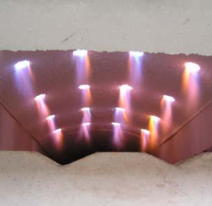
3 The EMB are metallic gas burners are used for direct heating. These burners allow excess air, stoichiomentric and excess gas regulation. Depending on the size and use, this type of burner can be used for natural gas and LPG combustion (in the standard version) and other types of gaseous combustive agents with heating different properties (special versions on request). APPLICATIONS ¾Ceramic furnaces or fibre cover treatment furnaces. ¾Tunnel or chariot furnaces. ¾Dryers. ¾Textile and dry cleaning machines (Rameause). ¾Stretching furnaces. F3400I03 CHARACTERISTICS GENERAL: ¾Capacity: From 20 to kw ¾Temperature limit: C ¾Air and gas pressure to burner: 45mbar ¾Flow ratio: 8 : 1 ¾Flame speed: m/s ¾Low CO2 content: <10PPM (@ 3% O 2 ) ¾Excess air: up to 400% MATERIAL COMPOSITION: ¾Mixer body: ¾Gas collector: ¾Flameproof tube: ¾Combustion head: ¾Fixing flange: Cast iron G25 Cast iron G25 AISI304 AISI310 Fe F3400I04 3
4 PARAMETER CAPACITY AND FLAME LENGTH The EMB burner ignition takes place through a high tension discharge obtained via an electrode and the detection is performed by another electrode. Both are included with the supply. The adoption of flame control systems is highly recommended in all plants operating at temperatures lower than 750 C (UNI EN746/2 Regulation). Model Capacity [kw] Flame length [mm] Flame tube outlet diameter [mm] Flame speed [m/s] Flame ignition and detection EMB N.1 WAND electrode EMB N.2 WAND electrodes EMB N.2 WAND electrodes EMB N.2 EN electrodes EMB N.2 EN electrodes EMB N.2 EN electrodes EMB N.2 EN electrodes EMB N.2 EN electrodes EMB N.2 EN electrodes The flame lengths and velocities are approximate, they refer to burners fed by natural gas that are placed in open air and function in stoichiometric ratio at nominal capacity. In special applications, mono-electrodes for the ignition and flame detection are used or else an electrode for flame ignition and a UV photocell for the flame detection is used. DESCRPTION The EMB metallic burners are "nozzle mix" type burners. The fuel and combustive agents are mixed at the combustion head to avoid dangerous flame flashbacks. Furthermore, the special shape of the combustion head allows regulation in stoichiometric ratio as well as in excess air. The EMB burners develop the maximum capacity in stoichiometric ratio with 45mbar of air pressure. This implies the use of low prevalence blowers which are also inexpensive; the setting is simplified due the special differential pressure plugs that allow the measurement of air and gas flow. 4
5 BURNER PERFOMANCE The flame capacity, length and speed refer to a natural gas fed burner (8600 Kcal/Nm³) placed in a combustion chamber at zero pressure above sea level, functioning with 10% of excess air. ¾Chamber temperature 1000 C ¾NOx < 200 mg/nm 3 [O 2 = 3% ref.] ¾Room air temperature MAXIMUM CAPACITY Max capacity Free flame application Burner model EMB-0 EMB-1 EMB-2 EMB-3 EMB-4 EMB-5 EMB-6 EMB-7 EMB-8 Burner capacity (2% O 2 ) [kw] Combustion air flow [Nm 3 /h] Gas flow [Nm 3 /h] Burner air inlet pressure [mbar] 45 Δp flange gas measurement [mbar] 10 MINIMUM CAPACITY Min capacity Free flame application Burner model EMB-0 EMB-1 EMB-2 EMB-3 EMB-4 EMB-5 EMB-6 EMB-7 EMB-8 Burner capacity(2% O 2 ) [kw] Combustion air flow [Nm 3 /h] 2,2 3,3 8,8 16, ,5 Gas flow [Nm 3 /h] 0,2 0,3 0,8 1,5 3,0 4,0 6,0 9,0 15,0 Burner air inlet pressure [mbar] 0,5 Δp flange gas measurement [mbar] 0,1 5

 @ 30 C P.")
6 NATURAL GAS CAPACITY TABLE AIR CAPACITY TABLE Burner feeding pressure [mbar] Differential pressure at orifice flow meter [mbar] Natural gas 20 C P.S.=0,6 [Nm 3 /h] G3004I01 Total air flow (burner + 30 C P.S.= 1 [Nm3/h] G3004I02 6
7 FLOW SCHEME -FREE FLAME METALLIC BURNER D3004I01 Pos. Description Included Not included 1 Main gas interception ball valve X 2 Balanced modulator X 3 Impulse line X 4 Servo-controlled air regulation butterfly valve X 5 Electric servo-control X 6 Single burner gas interception ball valve X 7 Main burner safety gas solenoid valve X 8 DP gas measurement calibrated flange X 9 Gas passage limiting device X 10 Manual air regulation butterfly valve X 11 DP inlet air pressure measurement calibrated orifice X 12 Free flame burner X 13 Ignition transformer X 14 Flame control X 15 Premix air regulation kit (only LPG versions) X 7
8 FLOW SCHEME -FREE FLAME METALLIC BURNER D3004I02 Pos. Description Included Not included 1 Main gas interception ball valve X 2 Balanced modulator X 3 Impulse line X 4 Servo-controlled air regulation butterfly valve X 5 Electric servo-control X 6 Single burner gas interception ball valve X 7 Main burner safety gas solenoid valve X 8 DP gas measurement calibrated flange X 9 Gas passage limiting device X 10 Manual air regulation butterfly valve X 11 DP inlet air pressure measurement calibrated orifice X 12 Free flame burner X 13 Ignition transformer X 14 Flame control X 15 Premix air regulation kit (only LPG versions) X 8
9 WARNINGS ¾ The EMB burner ignition must always be carried out at minimum power, modulating towards the maximum, facilitating the ignition and reducing the outlet overpressures. Thus it is opportune to use slow opening solenoid valves on the fuel line. ¾ The passing from minimum to maximum power and vice-versa, must be gradual and not instantaneous. In double stage regulations, the use of MRBV regulation valves (data sheet E1302) is suggested. ¾ For all low temperature applications (up to 750 C), the burner ignition and the fuel gas solenoid valve commands must be performed via a certified burner control device. ¾ To avoid possible damage to burners, make sure that the blower does not send them air that may be fouled by combustion products, oils, solvents or other. To avoid these phenomena from taking place, possibly install the blower or the suction duct outside the establishment and far from the exhaust pipes. ¾ Check the correct connection of the feeding lines after installation. Before switching the burner on, check that the combustive air and fuel gas pressure values are correct (Pag.05). ¾ The burner can only function within the indicated power range. Functioning at lower or higher powers could compromise the burner performance as well as its life span. In which case, the general warrantee conditions will automatically expire and ESA will not be held responsible for any damage to persons or things. ¾ If there is trouble with other devices during the burner start up phase, use the connector with anti disturbance filter for the high-tension (HT) cable connection of the ignition electrode. ¾ Avoid burner ignition close to each other so as not to heat the ignition command system devices (solenoid valves and transformers). Prewash time lapse + first safety time lapse + min. of 5 sec. = time lapse between one ignition and another. (however, do not attempt more than 2 ignitions during a 30sec. time lapse). ¾ Make sure the power supply is TURNED OFF when intervening on the burner and its devices. In case of burner malfunctioning, follow the indications in the 'Maintenance' chapter of the present manual or contact ESA-PYRONICS assistance. ¾ Any modification or repair done by third parties can compromise the application safety and automatically cause the general warrantee conditions to expire. 9

10 INSTALLATION The EMB series burners are supplied with a special furnace wall fixing flange. The light obtained for the burner housing must leave open space around the burner. This space has then to be filled with ceramic-fibre. For the installation carefully follow the instructions below: 1 - Place the EMB burners far from heat sources and products such as: liquids, solvents or corrosive gases. 2 - Make sure that the housing dimensions and the distance between the centers of the feeding pipes correspond to what is specified in the "Overall dimensions" chapter. 3 - Assemble the burner on the furnace wall (pos. 01) interposing a ceramic fibre gasket between the attachment flange and the furnace wall (pos.02). During the burner insertion phase check that the insulation previously wrapped around the outside is not altered nor damaged. Once the spacer has been fixed onto the furnace, from the inside of the combustion chamber, seal any possible cracks that may be left between the wall and the spacer with ceramic fibre. 4 - Connect the combustion air and fuel gas inlet piping, interposing, if possible, dilation joints in AISI. D3004I Connect electricity to the ignition electrode and to the uv-scan detector making sure not to pass the conductors near heat sources. 6 - Check that the burner body and all its metallic elements are earthed with appropriate conductors. 7 - The connecting cable from the ignition transformer to the electrode must be specific for high tension and not screened. It must not be more than 1 metre long; otherwise the ignition transformer must be positioned near the burner. The high tension cable must be placed far from the power cables and not in metallic ducts. Ideally it should be left in open air. 8 - For further information please consult the technical data sheet concerning the ignition transformers. 9 - Connect electricity to the ignition electrode and to the uv-scan detector making sure not to pass the conductors near heat sources. D3004I
11 START-UP - SETTING The procedures indicated in the following chapter must be carried out by expert technicians. The non-observance of the instructions given can provoke dangerous conditions. 1 - Check that the combustion air pressure exiting the blower and the combustive fuel feeding pressure are both within the allowed range. 2 - Adjust the working pressure and the safety device pressure of the combustion plant, whether there is one per burner or one for the whole plant i.e. gas pressure reduction gear, block valve, relief valve, pressure switches etc. Simulate the intervention of all the safety devices including the intervention of the safety over temperature, checking that the fuel safety block devices act properly. 3 - Place the motorized air regulation valve in its maximum opening position and, via the gate valve, regulate the inlet air pressures to the burner, referring to the values indicated in the "burner performance" chapter for the maximum capacities (pag.05). 5 - Activate the burner control device and attempt the ignition until the burner switches on. While attempting to ignite the burner, act on the gas adjustment valve and, starting from the totally closed position, open it gradually until the burner ignites. 6 - Fully open the air regulation valve and adjust the maximum fuel capacity via the gas adjustment valve, checking the differential pressure created on the calibrated gas flange. 7 - Double check that, at minimum and maximum power, the burner inlet pressure corresponds to the values in the in the 'Parameter capacity" chapter. These values may be different depending on whether the burner is on or off. 8 - If necessary, with all burners turned onto the same power, analyse the combustion products in the chamber (where possible). 9 - Repeatedly attempt ignition at minimum burner power, with maximum amplitude, to check the ignition reliability and flame stability during the adjustment. 4 - Place the motorized air regulation valve in its minimum opening position and regulate its opening to obtain (in burner and ejector inlet) the relative minimum power pressure. PREMIX AIR FLOW SETTING WHERE SCHEDULED (LPG BURNERS) The premix line is supplied with the LPG burners. The setting must be carried out with burner off and in minimum flow conditions. The premix line must be fed by an inlet necessarily placed upstream the air flow regulation valve, whether it is in zone or interlocked by the main burner. 1. Place the burner in the minimum combustion air flow conditions. EMB-1: Gas body pressure = 2 mbar EMB-2: Gas body pressure = 2 mbar EMB-3: Gas body pressure = 2 mbar EMB-4: Gas body pressure = 2 mbar EMB-5: Gas body pressure = 2 mbar EMB-6: Δp = 6.5 mbar EMB-7: Δp = 2.5 mbar EMB-8: Δp = 5 mbar 2. Open the premix air tap. 3. Regulate the micrometric pin valve according to the following conditions: 4. Check, however, that at minimum power, the burner does not create black smoke on the combustion head and on the electrodes. In case this should occur, increase the premix air setting. 11
12 GENERAL MAINTENANCE PLAN Operation Type Advised time Notes High tension electrode connection O annual check integrity of outer plastic and oxidi -zation of internal electrode terminal. Electrode ignition / detection O annual replace if the kantal terminal is worn. Flanged tube combustion head O annual Replacement of gas side gaskets (**) S biennale Burner setting S annual Premix air setting (where scheduled) S annual during furnace stop, check that the two elements do not show signs of oxidization caused by high temperature Check that the gaskets are free of air leaks and that there is no vulcanization in the rubber From the inside check that there are no cracks in the refractory material every time the furnace is stopped for maintenance From the inside check that there are no cracks in the refractory material every time the furnace is stopped for maintenance NOTES: Key: O=ordinary / E=extraordinary (*) it is suggested that the gaskets on the gas side are replaced after every disassembly of the gas feeding line. (**) use high temperature gaskets 12
13 ORDINARY MAINTENANCE For correct dismantling and better maintenance of the EMB burner, meticulously follow the instructions below with the plant turned off. IGNITION AND FLAME DETECTION ELECTRODE REPLACEMENT 1 - Check that the burner control device is disconnected. 2 - Disconnect electrical supply to the electrodes (pos.01). 3 - Unscrew the connector (pos.02) at the base of the gas collector, removing the electrode (pos.03). 4 - Replace the faulty electrode (pos.03) paying attention to the correct repositioning of the new electrode. 5 - Reconnect the electrical supply (pos.01). 6 - Check the electrode's correct flame ignition/detection. D3400I
14 EXTRAORDINARY MAINTENANCE For correct dismantling and better maintenance of the EMB burner, meticulously follow the instructions below with the plant turned off. BURNER-SHUTDOWN For correct dismantling and better maintenance of the EMB burners, meticulously follow the instructions with the plant turned off. In shutdown conditions of the burner refer to the burner control device indications and to the relative manual to identify the cause. The main cases are indicated here below: ¾Illegal flame detection: the shutdown is due to an illegal flame detection during the phases prior to ignition or after the turning off. The causes are within the detection system (broken or faulty sensor or presence of humidity), or in the gas draw from the solenoid safety valve, which allows the burner to remain turned on. ¾Failed ignition: shutdown is caused due to the fact that no flame has been created during the starting process. The causes can be found in the start-up system (spark absence, faulty electrodes or incorrect position), in the bad setting of the fuel and combustion flow or in the detection system (faulty sensor or interrupted cables). More precisely, in the first two cases the flame is not ignited, while in the last case the flame is created but the burner control device is unable to detect it. ¾Flame signal loss: shutdown due to the loss of flame signal during the normal functioning of the burner. The causes can be found in the combustion air flow adjustment (rapid flow variations, adjustment out of allowed range). They can also be found in the detection system (faulty, dirty or badly positioned sensors). 14
15 EMB-0 OVERALL DIMENSIONS D3400I
16 EMB-1-CH4 OVERALL DIMENSIONS D3400I
17 EMB-1 LPG OVERALL DIMENSIONS D3400I
18 EMB-2-CH4 OVERALL DIMENSIONS D3400I
19 EMB-2 LPG OVERALL DIMENSIONS D3400I
20 EMB-3-CH4 OVERALL DIMENSIONS D3400I
21 EMB-3 LPG OVERALL DIMENSIONS D3400I
22 EMB-4-CH4 OVERALL DIMENSIONS D3400I
23 EMB-4 LPG OVERALL DIMENSIONS D3400I
24 EMB-5-CH4 OVERALL DIMENSIONS D3400I
25 EMB-5 LPG OVERALL DIMENSIONS D3400I
26 EMB-6-CH4 OVERALL DIMENSIONS Gas inlet Rp 2" X= Wall thickness Air inlet DN150 Gas inlet Ø 2" 100 Min. (a) Min. (a) Gas orifice flowmeter (included) Assembly by customer R A Ø Ø168 NOTES: (a) by customer Nr.4 holes Ø14 on 235 D.B.C. D3400I
27 EMB-6 LPG OVERALL DIMENSIONS 501± Premix air Inlet Rp 1.1/2" 94 Gas inlet Rp 1.1/2" 100 Min. (a) Min. (a) Gas inlet Ø 1.1/2" Gas orifice flowmeter (included) Assembly by customer 624 Air inlet DN150 Ø168 R A Ø X= Wall thickness NOTES: (a) by customer Nr.4 holes Ø14 on 235 D.B.C. D3400I
28 EMB-7-CH4 OVERALL DIMENSIONS CH4 inlet Rp 2" AIR inlet DN 150 Rp 2" X = WALL THICKNESS Rp 2" 217 Ø195 Ø207 Min=100mm (b) 67 Min=100mm (b) Gas orifice flowmeter (included) Assembly by customer Nr.4 holes Ø18 (a) NOTES: (a) Suitable on customer request (b) by customer Ø 360 (a) Ø 400 (a) D3400I
29 EMB-7 LPG OVERALL DIMENSIONS 454 ± Premix air inlet Rp 1/2" LPG inlet Rp 2" AIR inlet DN 150 X = WALL THICKNESS Ø195 Rp 2" Min=100mm (b) 67 Min=100mm (b) Gas orifice flowmeter (included) Assembly by customer Rp 2" Ø207 Nr.4 holes Ø18 (a) NOTES: (a) Suitable on customer request (b) by customer Ø360 (a) Ø400 (a) D3400I
30 EMB-8-CH4 OVERALL DIMENSIONS GAS INLET DN AIR inlet DN 200 X = WALL THICKNESS 217 Ø219.1 Ø88.9 Min.=100mm (b) 42 Min.=100mm (b) Ø88.9 Ø231 Nr.4 holes Ø18 (a) Gas orifice flowmeter (included) Assembly by customer NOTES: (a) Suitable on customer request (b) by customer Ø360 (a) Ø400 (a) D3400I
31 EMB-8 LPG OVERALL DIMENSIONS 454 ± Premix air inlet Rp 1/2" 150 GAS INLET DN AIR inlet DN 200 Ø X = WALL THICKNESS 226 Min.=100mm by customer 42 Min.=100mm by customer Ø88.9 Gas orifice flowmeter (included) Assembly by customer Ø Ø 231 Nr.4 holes Ø18 (a) NOTES: (a) Suitable on customer request (b) by customer Ø 360 (a) Ø 400 (a) D3400I
32 ORDERING CODE FOR COMPLETE BURNER EMB Model Flame length EMB-0 EMB-1 EMB-2... (see capacity table) Short flame ( 2 ) Long flame ( 3 ) Ignition and detection FC* FL ( 5 ) Gas adjuster 02 Ign. + det. Electrode Mono electrode Pilot burner ( 4 ) E* M P With gas adjuster Without gas adjuster GA* F 06 "X" flanged tube length Fuel 03 Indicate the length in mm (see overall dimenions)... Natural gas LPG Poor gas ( 1 ) CH4 GPL GP 07 Type of flanging According to ESA drawing According to Client's drawing E* C The codes marked with an asterisk (*) indentify the standards. Notes: 1 Particular performance according to gas characteristics 2 Standard version for free flame applications 3 Version for applications with burner placed in open tube. Available up to version 4. 4 Available in the 3,4,5 and 6 models (see "ignition and detection"paragraph). 5 In open radiant tube applications. 32
Free flame burners EMB (E3004 rev /02/2015)
") Burners Free flame burners EMB (E3004 rev. 08-10/02/2015) GENERAL WARNINGS: DISPOSAL: ¾ All installation, maintenance, ignition and setting must be performed by qualified staff, respecting the norms present
Burners Free flame burners EMB (E3004 rev. 08-10/02/2015) GENERAL WARNINGS: DISPOSAL: ¾ All installation, maintenance, ignition and setting must be performed by qualified staff, respecting the norms present
Burners. Pilot Heads BTC & BTSA (E3121 rev /04/2018)
") Burners Pilot Heads BTC & BTSA (E3121 rev. 02-24/04/2018) GENERAL WARNINGS: DISPOSAL: ¾ All installation, maintenance, ignition and setting must be performed by qualified staff, respecting the norms present
Burners Pilot Heads BTC & BTSA (E3121 rev. 02-24/04/2018) GENERAL WARNINGS: DISPOSAL: ¾ All installation, maintenance, ignition and setting must be performed by qualified staff, respecting the norms present
Burners. High velocity LOW NOx combustion air burners EMB-SIK-NxT (E3507 rev /11/2016)
") Burners High velocity LOW NOx combustion air burners EMB-SIK-NxT (E3507 rev. 05-28/11/2016) GENERAL WARNINGS: GENERAL NOTES: ¾ All installation, maintenance, ignition and setting must be performed by qualified
Burners High velocity LOW NOx combustion air burners EMB-SIK-NxT (E3507 rev. 05-28/11/2016) GENERAL WARNINGS: GENERAL NOTES: ¾ All installation, maintenance, ignition and setting must be performed by qualified
Burners. Pilot Heads BTC & BTSA (E3121 rev /09/2010)
") Burners Pilot Heads BTC & BTSA (E3121 rev. 01-06/09/2010) GENERAL WARNINGS: DISPOSAL: ¾ All installation, maintenance, ignition and setting must be performed by qualified staff, respecting the norms present
Burners Pilot Heads BTC & BTSA (E3121 rev. 01-06/09/2010) GENERAL WARNINGS: DISPOSAL: ¾ All installation, maintenance, ignition and setting must be performed by qualified staff, respecting the norms present
Orifice Flow Meters POP-S (E5720 rev /03/2013)
") Accessories Orifice Flow Meters POP-S (E5720 rev. 05-20/03/2013) GENERAL WARNINGS: DISPOSAL: ¾ All installation, maintenance, ignition and setting must be performed by qualified staff, respecting the norms
Accessories Orifice Flow Meters POP-S (E5720 rev. 05-20/03/2013) GENERAL WARNINGS: DISPOSAL: ¾ All installation, maintenance, ignition and setting must be performed by qualified staff, respecting the norms
Burners. Self-recuperative burners high speed with flat flame REKO-SIK-SW (E3903 rev /06/2015)
") Burners Self-recuperative burners high speed with flat flame REKO-SIK-SW (E3903 rev. 01-08/06/2015) GENERAL WARNINGS: DISPOSAL: ¾ All installation, maintenance, ignition and setting must be performed by
Burners Self-recuperative burners high speed with flat flame REKO-SIK-SW (E3903 rev. 01-08/06/2015) GENERAL WARNINGS: DISPOSAL: ¾ All installation, maintenance, ignition and setting must be performed by
Valves. Rapid opening and closing solenoid valves VMR (E1110 rev /11/2012)
") Valves Rapid opening and closing solenoid valves VMR (E1110 rev. 03-19/11/2012) GENERAL WARNINGS: DISPOSAL: ¾ All installation, maintenance, ignition and setting must be performed by qualified staff, respecting
Valves Rapid opening and closing solenoid valves VMR (E1110 rev. 03-19/11/2012) GENERAL WARNINGS: DISPOSAL: ¾ All installation, maintenance, ignition and setting must be performed by qualified staff, respecting
Burners. Self-recuperative burners high speed free flame REKO-SIK-FF (E3901FF rev /05/2009)
") Burners Self-recuperative burners high speed free flame REKO-SIK-FF (E3901FF rev. 04-06/05/2009) GENERAL WARNINGS: DISPOSAL: ¾ All installation, maintenance, ignition and setting must be performed by qualified
Burners Self-recuperative burners high speed free flame REKO-SIK-FF (E3901FF rev. 04-06/05/2009) GENERAL WARNINGS: DISPOSAL: ¾ All installation, maintenance, ignition and setting must be performed by qualified
Radiant tube burners RT (E3900 rev /01/2018)
") Burners Radiant tube burners RT (E3900 rev. 09-23/01/2018) GENERAL WARNINGS: DISPOSAL: ¾ All installation, maintenance, ignition and setting must be performed by qualified staff, respecting the norms present
Burners Radiant tube burners RT (E3900 rev. 09-23/01/2018) GENERAL WARNINGS: DISPOSAL: ¾ All installation, maintenance, ignition and setting must be performed by qualified staff, respecting the norms present
Burners. Ribbon linear flame burners AB & ABM (E3010 rev /11/2017)
") Burners Ribbon linear flame burners AB & ABM (E3010 rev. 09-14/11/2017) GENERAL WARNINGS: DISPOSAL: ¾ All installation, maintenance, ignition and setting must be performed by qualified staff, respecting
Burners Ribbon linear flame burners AB & ABM (E3010 rev. 09-14/11/2017) GENERAL WARNINGS: DISPOSAL: ¾ All installation, maintenance, ignition and setting must be performed by qualified staff, respecting
Valves. Slow opening and rapid closing solenoid valves VM-L (E1111 rev /11/2012)
") Valves Slow opening and rapid closing solenoid valves VM-L (E1111 rev. 03-19/11/2012) GENERAL WARNINGS: DISPOSAL: ¾ All installation, maintenance, ignition and setting must be performed by qualified staff,
Valves Slow opening and rapid closing solenoid valves VM-L (E1111 rev. 03-19/11/2012) GENERAL WARNINGS: DISPOSAL: ¾ All installation, maintenance, ignition and setting must be performed by qualified staff,
OIL REGULATORS RFG SERIES FEATURES APPLICATIONS DESCRIPTION INSTALLATION. Bulletin E5301 rev03 02/04/03. Body and valve seat: Shutter seat:
 OIL REGULATORS RFG SERIES FEATURES Body and valve seat: AVP Shutter seat: C40 Valve stem: AISI303 Diaphragm: anti-petrol rubbered fabrics Max viscosity: 3 E Max operating pressure: 7 bar Max differential
Valves. Double stage and modulant motorized butterfly valves MRBV & MRBV-CMAP (E1302 rev /04/2011)
") Valves Double stage and modulant motorized butterfly valves MRBV & MRBV-CMAP (E1302 rev. 04-07/04/2011) GENERAL WARNINGS: DISPOSAL: ¾ All installation, maintenance, ignition and setting must be performed
Valves Double stage and modulant motorized butterfly valves MRBV & MRBV-CMAP (E1302 rev. 04-07/04/2011) GENERAL WARNINGS: DISPOSAL: ¾ All installation, maintenance, ignition and setting must be performed
Electronics. Permanent operation microprocessor burner control device ESA GENIO-S (E7021 rev /05/2015)
") Electronics Permanent operation microprocessor burner control device ESA GENIO-S (E7021 rev. 01-06/05/2015) GENERAL WARNINGS: GENERAL NOTES: ¾ All installation, maintenance, ignition and setting must be
Electronics Permanent operation microprocessor burner control device ESA GENIO-S (E7021 rev. 01-06/05/2015) GENERAL WARNINGS: GENERAL NOTES: ¾ All installation, maintenance, ignition and setting must be
Electronics. Permanent operation microprocessor burner control device ESA GENIO-PRS (E7022 rev /05/2015)
") Electronics Permanent operation microprocessor burner control device ESA GENIO-PRS (E7022 rev. 01-13/05/2015) GENERAL WARNINGS: GENERAL NOTES: ¾ All installation, maintenance, ignition and setting must
Electronics Permanent operation microprocessor burner control device ESA GENIO-PRS (E7022 rev. 01-13/05/2015) GENERAL WARNINGS: GENERAL NOTES: ¾ All installation, maintenance, ignition and setting must
Electronics. Permanent Operation Microprocessor Burner Control ESA ESTRO-PO (E7014PO rev /05/2013)
") Electronics Permanent Operation Microprocessor Burner Control ESA ESTRO-PO (E7014PO rev. 01-21/05/2013) GENERAL WARNINGS: DISPOSAL: ¾ All installation, maintenance, ignition and setting must be performed
Electronics Permanent Operation Microprocessor Burner Control ESA ESTRO-PO (E7014PO rev. 01-21/05/2013) GENERAL WARNINGS: DISPOSAL: ¾ All installation, maintenance, ignition and setting must be performed
North American 4485 Tempest SE
 Combustion North American 4485 Tempest SE Medium/High Velocity Gas Burner Low NOx gas burner, durable construction and flexible desgin to fit a variety of applications. NPT or BSP air/gas inlets, adjustable
Field proven low emissions. State-of-the-art low NOx firing - adjustable for application flexibility
 -.9- KINEDIZER LE High capacity low NOx gas burners Field proven low emissions. State-of-the-art low NOx firing - adjustable for application flexibility Lower NOx and less excess air than standard KINEDIZER
Specifications of STICKTITE and PILOTPAK Nozzles
 -.-5 Specifications of STICKTITE and PILOTPK Nozzles This graph indicates the relationship between capacity and applied mixture differential pressure for STICKTITE and PILOTPK nozzles when fed with an
KINEMAX. Medium velocity gas or oil burners
 KINEMAX Medium velocity gas or oil burners High Temperature Burners - KINEMAX -.- Exit velocities up to 00 km/h (8 m/s) to promote workload heat penetration and better furnace temperature uniformity Operate
2.0 Burner Operating Parameters and Requirements
 ECLIPSE INFORMATION GUIDE Silicon Carbide Radiant Auto-Recupes Info 322 2/99 WARNING Handle silicon carbide tubes carefully. Do not drop them or hammer on them. Although they feature excellent mechanical
Specifications of STICKTITE and PILOTPAK Nozzles
 Low Temperature urners - STICKTITE and PILOTPK Nozzles 1-1.1-5 Specifications of STICKTITE and PILOTPK Nozzles This graph indicates the relationship between capacity and applied mixture differential pressure
Info 110 4/98. RatioMatic Burners. RM Series version through 600 Sizes. 750 through 2000 Sizes
 Info 110 4/98 RatioMatic Burners RM Series version 1.01 50 through 600 Sizes 750 through 2000 Sizes For Ratiomatic Serial Numbers 95-5500 and Above Version 1.01 7/97 Contents 1.0 Operating Parameters &
INDUSTRIAL MICRODIFFUSION DUAL-FUEL BURNERS
 Operations and Maintenance Manual for INDUSTRIAL MICRODIFFUSION DUAL-FUEL BURNERS Models MD-25-OG MD-7500-OG December 2012 Copyright 2012 Periflame, Design Guide 113 Industrial Dual-Fuel Burners, 12/01/2012
LVDT/HC PILOT BURNER. External raw gas pilot burner
 4-22.4-1 LVDT/HC PILOT URNER External raw gas pilot burner Stable pilot flame in combination with MXON IRFLO LV, HC, DELT-TE and COMUSTIFUME burners Rugged design urns natural gas, propane and LPG Suitable
PREMIX TUNNEL BURNERS
 FOR ENCLOSED GASAIR COMBUSTION MODEL: 01, 0, 06 Revision: 0 BULLETIN 01, 0, 06 EXPLODED VIEW Pyronic Tunnel Burners will burn any standard fuel gas at mixture pressures ranging from 0.1 to 60 W. C. Exclusive,
ONE STAGE GAS BURNER GULLIVER RSF SERIES RS5F kw
 ONE STAGE GAS BURNER GULLIVER RSF SERIES 160 330 kw The Riello Gulliver, is a new model of the series of one stage gas burners, developed to respond to any request for light industrial processes like bakery
VF VFH. elektrogas.com. Butterfly valves DN40 DN150 EE155-11/11
 VF VFH Butterfly valves DN40 DN150 elektrogas.com EE155-11/11 VF VFH Butterfly valves Contents Description.. 2 Features...... 2 Functioning and application.. 3 Technical specifications.... 4 Flow chart
Eclipse RatioAir Burners
 Parameter Maximum Input, BTU/hr (kw) 1, Minimum Input, BTU/hr (kw) Lower inputs may be achieved. Contact factory. Main Gas Inlet Pressure, "w.c. (mbar) 3 Fuel pressure at ratio regulator inlet. High Fire
MULTIFIRE. High temperature dual fuel burner
 MULTIFIRE High temperature dual fuel burner High temperature burners - MULTIFIRE 3-11.3-1 Operates on-ratio or with excess air to meet the specific demands of your combustion process needs Burns most clean,
all combustible gases and fuel oil, extra light gases up to 1 bar, fuel oil up to 40 bar Fuel Connection gases ½, fuel oil ¼
 Technical Specification High Velocity Burner Type HV Content 1 Type Designation Code Key Technical Data 3 Deployment and Mode of Operation 4 Basic Construction of the Burner Installation and Startup.1
X4 Installation and Operation Manual - POWER FLAME INCORPORATED
 7.13.2 Set the burner s combustion air inlet damper to the approximate setting as shown in this manual for the desired firing rate. Also, verify that the correct main orifice is installed in the main orifice
RS/E-EV MZ SERIES. Modulating Gas Burners FIRING RATES
 The RS/E-EV MZ burners series covers a firing range from 44 to 2650 kw, and it is based on a new Digital Burner Management System, Riello REC27, which is able to manage the air-fuel ratio by independent
RS/1 SERIES. One Stage Gas Burners RS 34/1 MZ RS 44/1 MZ kw kw GAS
 The RS/1 series of burners covers a firing range from 70 to 550 kw, and they have been designed for use in low or medium temperature hot water boilers, hot air or steam boilers, diathermic oil boilers.
PRESSURIZED STEEL BOILER WITH REVERSED FLAME
 smoke pipes PRESSURIZED STEEL BOILER WITH REVERSED FLAME OUTPUT RANGE from 340 to 7000 WORKING TEMPERATURE minimum return temperature 55 OPERATION WITH gas or oil fired jet burners MODELS 340 420 510 630
ATTENTION: Industrial machinery for professional use. These instructions are for qualified personnel USE AND MAINTENANCE MANUAL
 USE AND MAINTENANCE MANUAL PUMPING HEADS ATTENTION: Industrial machinery for professional use. These instructions are for qualified personnel METERING PUMP WITH SPRING RETURN SR Series mod. B HYDRAULIC
North American 4575 HiRAM
 Combustion North American 4575 HiRAM The quality and performance of our Tempest, but bigger. Low NOx burner High Velocity - High Turndown Inputs to 4-25 million Btu/hr Direct Spark or Pilot Lighting Furnace
VALUPAK. Packaged gas burners
 VALUPAK Packaged gas burners Low Temperature Burners - VALUPAK 1-1.5-1 High turndown. Available in 6 sizes. Capacities: 2 kw -1124 kw (HHV). Stable and clean combustion. Suitable for UV scanner and flame
1470 SERIES HOT AIR GAS BURNER
 1 SERIES HOT AIR GAS BURNER CAPABILITIES High or low temperature furnace High excess air 800% or more Ratio or tempered flame operation Nominal capacity range 0,000 to 3.5 MM Btu/hour Suitable for light
G72x Series Direct Spark Ignition Controls
 Installation Sheets Manual 121 Gas Combustion Combination Controls and Systems Section G Technical Bulletin G72x Issue Date 1299 G72x Series Direct Spark Ignition Controls Figure 1: G72x Direct Spark Ignition
TWO STAGE GAS BURNER GULLIVER RSD SERIES RS5D 160/ kw
 TWO STAGE GAS BURNER GULLIVER RSD SERIES 160/208 345 kw The Riello Gulliver is a new model of the series of two stage gas burners, characterized for its small dimensions in spite of its high combustion
Oil, gas and dual fuel burners. Burner series
 Oil, gas and dual fuel burners Burner series 350...450 Group 4B Capacity 700-5500 kw 1 2 Table of contents General 5 Light fuel oil burners 6 Dimensions and PI diagram 6 Technical data 7 Capacity/back
1200 SERIES FTR HOT AIR BAFFLE BURNER
 CAPABILITIES High release rates with moderate air pressure Good turn down with flame characteristics and direction maintained Stable flames tailored to the job applications can be from highly oxidizing
HOT WASHER MODEL NO: KING 125 OPERATION & MAINTENANCE INSTRUCTIONS PART NO: LS1009
 HOT WASHER MODEL NO: KING 125 PART NO: 7320170 OPERATION & MAINTENANCE INSTRUCTIONS LS1009 INTRODUCTION Thank you for purchasing this Hot Washer. This machine is a portable, high pressure power washer,
Specifications of LVDT/HC-pilot burner. Materials of construction. Duct burners - LVDT/HC-pilot burner. combustion systems for industry
 4-22.4-4 Specifications of LVDT/HC-pilot burner Typical burner data 15 C 21 % O 2 combustion air 50 % humidity natural gas with 10.9 kwh/m³(st) HHV - sg = 0.6 [1] Stated pressures are indicative - actual
RS SERIES. Two Stage Progressive Gas Burners FIRING RATES
 The RS burners series covers a firing range from 44 to 2290 kw, and it has been designed for use in low or medium temperature hot water boilers, hot air or steam boilers, diathermic oil boilers. Operation
TWO STAGE PROGRESSIVE AND MODULATING GAS BURNERS RIELLO 40 GS/M SERIES GS 10/M 22/ kw GS 20/M 43/ kw
 TWO STAGE PROGRESSIVE AND MODULATING GAS BURNERS RIELLO GS/M SERIES GS /M / 5 3/8 19 The Riello GS/M series of two stage progressive or modulating gas burners, is a complete range of products developed
822 NOVAMIX GAS FLOW RATE ADJUSTMENT AS A FUNCTION OF THE AIR FLOW GAS/AIR RATIO 1:1 DOUBLE AUTOMATIC SOLENOID SHUT-OFF VALVE
 SIT Group 822 NOVAMIX MULTIFUNCTIONAL GAS CONTROL GAS FLOW RATE ADJUSTMENT AS A FUNCTION OF THE AIR FLOW GAS/AIR RATIO 1:1 DOUBLE AUTOMATIC SOLENOID SHUT-OFF VALVE SERVO-CONTROLLED PRESSURE REGULATOR PIN
PNEUMATIC PUMP Series
 PNEUMATIC PUMP Series 3103... User and Maintenance Manual Original text translation TABLE OF CONTENTS 1. INTRODUCTION 2. GENERAL DESCRIPTION 3. PRODUCT-MACHINE IDENTIFICATION 4. TECHNICAL CHARACTERISTICS
available in battery up to 4 units for a total of 560 kw
 MODULATING CONDENSING BOILER with double premix low NOx burner and double heat exchanger EXPANDABLE IN BATTERY for indoor and outdoor installations (IPX5D) OUTPUT RANGE from 10 to 560 kw (in battery) WORKING
LOW NOx TWO STAGE GAS BURNERS GULLIVER BSD SERIES BS1D 16/19 52 kw BS2D 35/40 91 kw BS3D 65/ kw BS4D 110/ kw
 LOW NOx TWO STAGE GAS BURNERS GULLIVER BSD SERIES 1/19 5 kw 35/4 91 kw 5/75 19 kw 11/14 4 kw The Riello Gulliver BSD series of two stage gas burners, is a complete range of Low NOx emission products, developed
Low emissions, high performance natural gas burners
 -.6- OVENPAK LE Burners Low emissions, high performance natural gas burners Burns any clean fuel gas Operates on low gas supply pressures Provides clean combustion with low NOx and CO levels Compact burner
NOx-Beta Ultra Low NOx Burners
 NOx-Beta Ultra Low NOx s February NOx-Beta Features Ultra low NOx without any performance loss Staged air principle no external NOx reducing devices or FGR needed Robust, well engineered construction Cost
Installation- and maintenance instruction ST120 S75/21
 Installation- and maintenance instruction ST120 S75/21 1 171 615 30 05-01 178 058 15 DESCRIPTION Components 1. Reset button 2. Control box 3. Ignition transformer 4. Ignition cables 5. Nozzle assembly
US - UP2/OIL 12V US - UP2/OIL 24V
 SELF PRIMING ELECTRIC PUMP FOR TRANSFERRING LUBRICATING OILS OR VISCOUS FLUIDS INSTRUCTIONS FOR USE 164 220 12-US - UP2/OIL 12V 164 220 13-US - UP2/OIL 24V 15/05/14 Rev.02 A PRODUCT DESCRIPTION Self-priming
VQ400M SERIES CLASS A COMBINATION VALVES PRODUCT HANDBOOK APPLICATION
 VQ400M SERIES PRODUCT HANDBOOK APPLICATION The VQ400M Series class A safety combination valves are used for control and regulation of gaseous fluids in gas power burners, atmospheric gas boilers, melting
Mobile Diesel Heaters GRY-D / GRY-I Service Training Course
 Mobile Diesel Heaters GRY-D / GRY-I Service Training Course 1 Rev. No. 3 January 24, 2011 GRY-I Indirect-fired Diesel Heaters GRY-I 15 WU GRYP 50 AP GRY-I 25 WU GRYP 90 AP GRY-I 40 WU GRYP 135 AP 2 GRY-D
![[Vacuum valves and solenoid valves] 4](/thumbs/95/125066489.jpg "[Vacuum valves and solenoid valves] 4")
Low Temperature Burners - STICKTITE and PILOTPAK Nozzles
 Low Temperature Burners - STICKTITE and PILOTPK Nozzles STICKTITE & PILOTPK Flame retention nozzles -.- For open-port firing or open environment firing Provides positive flame retention and stable clean
ONE STAGE GAS BURNERS RS/1 SERIES RS 28/ kw RS 34/1 MZ kw RS 38/ kw RS 44/1 MZ kw
 ONE STAGE GAS BURNERS RS/1 SERIES RS 28/1 163 349 kw RS 34/1 MZ 7 39 kw RS 38/1 232 465 kw RS 44/1 MZ 55 kw The RS/1 series of burners covers a firing range from 7 to 55 kw, and they have been designed
VGD20... VGD40... Double Gas Valves. Siemens Building Technologies Landis & Staefa Division
 7 631 ISO 9001 VGD40... Double Gas Valves VGD40... Double gas valves for use on gas trains, consisting of 2 safety shut-off valves of class A. Suited for use with gases of gas families I...III. The double
VAL6 KBE5S. Service Manual
 VAL6 KBE5S Service Manual 1 2 Specifications Type VAL6 KBE5S Heat Output 111,000BTU/h Fuel Kerosene, Diesel Tank Capacity 9 gallons Fuel Consumption 0.85gallon/h Power Source 120V, 60Hz single phase Power
RS/M SERIES. Modulating Gas Burners FIRING RATES
 The RS/M burners series covers a firing range from 45 to 2650 kw, and it has been designed for use in low or medium temperature hot water boilers, hot air or steam boilers, diathermic oil boilers. Operation
VALIADIS S.A. HELLENIC MOTORS
 Explosion proof motors MAK 56-250 (MAKe 63-250) series Groups IIB and IIC Ex db / Ex db e (EPL) executions Gb or Ex tb IIIC (EPL) Db II 2 G, II 2D, 2GD SAFETY INSTRUCTIONS Safety Instructions MAK and MAKe
Safety. Operating instructions Solenoid valve for gas VG 6 VG 15/10 DANGER. Contents WARNING CAUTION. Changes to edition 07.15
 17 Elster GmbH Edition 1.17 Translation from the German 519 D F NL I E DK S N P GR TR CZ PL RUS H www.docuthek.com Operating instructions Solenoid valve for gas VG VG 15/1 Contents Solenoid valve for gas
North American Combustion Burners
 Combustion North American Combustion Burners 4441 North American Tempest High Velocity Gas Burner Jet action burner offering superior recirculation Slotted tile produces exceptional temperature uniformity
PRESS G SERIES. Two Stage Light Oil Burners FIRING RATES
 The PRESS G series of burners covers a firing range from 107 to 1660 kw and they have been designed for use in civil installations of average dimensions, like building areas and large apartment groups
ONE STAGE GAS BURNERS RDBS SERIES
 ONE STAGE GAS BURNERS RDBS SERIES 16 47 kw RDBS.1 16 47 kw The Riello RDBS is a new series of one stage gas burners with integrated gas train, characterised by its small dimensions in spite of its high
SARGON S - M - L. All rights reserved INSTALLATION MANUAL
 INSTALLATION MANUAL Our compliments for your excellent choice. SARGON LINE S (300mm) M (400mm) and L (600mm) electro-mechanical gear motor has been produced for reliability and high quality. This Manual
FABER BURNER ROUTINE MAINTENANCE
 FABER BURNER ROUTINE MAINTENANCE Version 2016 The Faber burner is designed for minimal maintenance; however, the frequency and quantity of maintenance that is required depends upon many factors which vary
Installation- and maintenance instruction BENTOFLEX ST 108 PL
 Installation- and maintenance instruction BENTOFLEX ST 108 PL 1 171 625 30 03-01 178 001 13 DESCRIPTION COMPONENTS 1. Reset button 2. Control box 3. Ignition transformer 4. Ignition cables 5. Nozzle assembly
TWO STAGE LIGHT OIL BURNERS PRESS G SERIES
 TWO STAGE LIGHT OIL BURNERS PRESS G SERIES 7/178 356 kw PRESS 1G 13/19 534 kw PRESS 2G 214/356 712 kw PRESS 3G 273/534 1168 kw PRESS 4G 415/83 166 kw The PRESS G series of burners covers a firing range
INSTALLATION, OPERATION AND MAINTENANCE TECHNICAL MANUAL
 ISO 9001:2008 Via Renata Bianchi, 12 16152 Genova ITALY Tel. +39.01.6017016 Fax. +39-010-601-6021 www.tecnidro.com s INDEX 1. Introduction 1.1 Premise 1.2 Generality 1.3 Principle of operation 2. INSTALLATION
Oil, Gas and Dual Fuel Burners
 Oil, Gas and Dual Fuel Burners Burner series 130...150 50, 0 Group 3 Capacity 390-3,500 Table of contents General 1 How to choose a burner Light oil burners Technical data and dimensions 3- PI-diagrams
VQ400M SERIES CLASS A COMBINATION VALVES PRODUCT HANDBOOK APPLICATION
 VQ400M SERIES PRODUCT HANDBOOK APPLICATION The VQ400M Series class A safety combination valves are used for control and regulation of gaseous fluids in gas power burners, atmospheric gas boilers, melting
Installation- and maintenance instruction BENTOFLEX ST120KAV
 Installation- and maintenance instruction BENTOFLEX ST120KAV 1 171 625 61 05-01 178 001 16 DESCRIPTION COMPONENTS 1. Reset button 2. Control box 3. Ignition transformer 4. Ignition cables 5. Nozzle assembly
RatioAir Burners. Model RA0750. Data /31/05. Main Specifications - RA0750
 Main Specifications - RA0750 PARAMETER Maximum input, Btu/hr (kw) at neutral chamber conditions. (Natural Gas) 60Hz Packaged 50Hz Packaged Minimum input, Btu/hr (kw) Lower inputs may be achieved. Contact
GAS BURNERS BLU 3000 PR BLU 4000 PR
 GAS BURNERS techniques for energy saving MODELS BLU 3000 PR BLU 4000 PR 220/380 V 60 Hz L.P.G. LB 450 03.03.97 TECHNICAL DATA MODELS BLU 3000 PR BLU 4000 PR Thermal power max. kcal/h 2.580.000 3.440.000
Doing more for clean environment and energy saving
 Doing more for clean environment and energy saving Rütli Burners Switzerland AG is a worldwide leading industrial burner solution supplier. Our head quarter is located in Schaffhausen, Switzerland one
VALUPAK. Packaged gas burners
 VALUPAK Packaged gas burners 1-1.5-1 E - i - 11/14 High turndown. Available in 6 sizes. Capacities: 0.007 MBtu/hr - 4 MBtu/hr. Stable and clean combustion. Suitable for UV scanner and flame rod. Natural
RatioAir Burners. Model RA1000. Data /31/05. Main Specifications - RA1000
 Main Specifications - RA1000 PARAMETER Maximum input, Btu/hr (kw) at neutral chamber conditions. (Natural Gas) 60Hz Packaged Blower 50Hz Packaged Blower Minimum input, Btu/hr (kw) Lower inputs may be achieved.
Installation- and maintenance instruction BENTOFLEX ST133K
 Installation- and maintenance instruction BENTOFLEX ST133K 171 625 37 07-01 178 004 17 TECHNICAL DATA Type designation ST133K Dimensions B 200 258 ø89 54 237 158 295 Burner tube Length of burner tube Incl.
Instructions. for Installation, Operation and Maintenance of ABO Butterfly Valves, Series 600 and 900
 Instructions for Installation, Operation and Maintenance of ABO Butterfly Valves, Series 600 and 900 1. Instructions 2. Valve Description 3. Installation 4. Operation 5. Removal 6. Maintenance 7. Repairs
E Series CE Approved Intermittent Pilot Ignition Control
 Installation Instructions Issue Date January 11, 2013 E Series CE Approved Intermittent Pilot Ignition Control Application The E Series CE Approved Intermittent Pilot Ignition Control is a safety control
DB Series. Technical Data Leaflet. Industrial Dual Block Oil, Gas and Dual Fuel Burners. Industrial TS0086UK00
 Technical Data Leaflet Industrial TS0086UK00 DB Series Industrial Dual Block Oil, Gas and Dual Fuel Burners DB 4 1000/2500 5000 kw DB 6 1400/4000 7800 kw DB 9 1500/5000 9500 kw DB 12 1700/7000 12500 kw
Safety. Operating instructions Solenoid valve VGP DANGER. Contents WARNING CAUTION. Changes to edition Elster GmbH Edition 10.
 27 Elster GmbH Edition.7 Translation from the German 344297 D F NL I E DK S N P GR TR CZ PL RUS H www.docuthek.com Operating instructions Solenoid valve Contents Solenoid valve... Contents... Safety....
Specifications of OPTIMA SLS Burners
 1.1.9-4 Low emperature urners - PIM L pecifications of PIM L urners ypical burner data Fuel: natural gas at 60 F with 1000 tu/ft 3 (st) HH - sg = 0.6 (1) ombustion air: 60 F - 21% 2-50% humidity - sg =
TECHNICAL DATA LEAFLET GAS. RS/1 Series. One Stage Gas Burners. RS 34/1 MZ kw RS 44/1 MZ kw.
 TECHNICAL DATA LEAFLET GAS RS/1 Series One Stage Gas Burners RS 34/1 MZ 7 39 kw RS 44/1 MZ 1 kw www.riello.com One Stage Gas Burners RS/1 Series The RS/1 series of burners covers a firing range from 7
Governor with solenoid valve VAD Air/gas ratio control with solenoid valve VAG
 Governor with solenoid valve Air/gas ratio control with solenoid valve All-purpose servo-governor for gaseous media with integrated safety valve Suitable for a max. inlet pressure of 500 mbar Outlet pressure
INSTALLATION OPERATION AND MAINTENANCE MANUAL SMITSVONK HIGH ENERGY IGNITION UNIT TYPE: E-LIGHT
 INSTALLATION OPERATION AND MAINTENANCE MANUAL SMITSVONK HIGH ENERGY IGNITION UNIT TYPE: E-LIGHT-161609 Read before commencement of all work! This ignition unit must be mounted in accordance with the applicable
G76x Direct Spark Ignition Controls
 Installation Sheets Manual 121 Gas Combustion Combination Controls and Systems Section G Technical Bulletin G76x Issue Date 0400 G76x Direct Spark Ignition Controls Figure 1: G76x Direct Spark Ignition
SENSOR MUT2300. Electromagnetic flowmeter. The electromagnetic flowmeter designed for the toughest applications DS401-1-ENG
 SENSOR MUT2300 Electromagnetic flowmeter The electromagnetic flowmeter designed for the toughest applications DS401-1-ENG Sensor MUT2300 The MUT2300 sensors represent the state of the art of Euromag International
Electromagnetic flowmeters
 02/97 Electromagnetic flowmeters Primary heads Installation instructions ECOFLUX IFS 1000 F Compact flowmeters IFM 1010 K IFM 1080 K CONTENTS Installation in the pipeline Pages 4-5 and 7-8 Grounding Pages
DIAPHRAGM PUMPS: Instruction Manual
 INTRODUCTION DIAPHRAGM PUMPS: Instruction Manual Congratulations for choosing a product Imovilli Pompe, the result of a careful manufacturing process supported by over fifty years of specific experience
VML. elektrogas.com. Safety solenoid valves for gas Slow opening and fast closing type DN10 DN80 EE
 VML Safety solenoid valves for gas Slow opening and fast closing type DN10 DN80 elektrogas.com EE162-1208 VML Safety solenoid valves for gas Slow opening and fast closing type Contents Description.. 2
North American Combustion Burners
 Combustion North American Combustion Burners 4441 North American Tempest High Velocity Gas Burner Jet action burner offering superior recirculation Slotted tile produces exceptional temperature uniformity
Ignition Reliability in SGT-750 for Gas Blends at Arctic Conditions. Magnus Persson Combustion Expert / Distributed Generation / Sweden
 Ignition Reliability in SGT-750 for Gas Blends at Arctic Conditions Magnus Persson Combustion Expert / Distributed Generation / Sweden siemens.com/power-gas Table of content Objectives of the Project SGT-750
G600 Series Replacement Intermittent Pilot Ignition Controls
 Installation Instructions G600 Issue Date 0601 G600 Series ment Intermittent Pilot Ignition Controls Installation IMPORTANT: These instructions are intended as a guide for qualified personnel installing
XID ENHANCEMENT SYSTEM IMPROVED EFFICIENCY AND PERFORMANCE
 IMMERSION FIRED HOT WATER BOILER April 1, 2003 GENERAL DESCRIPTION The Sellers immersion fired hot water boiler is a horizontal, single pass, firetube boiler designed to burn natural gas. The unique burner
EVS RP6020. Instruction Manual
 Instruction Manual TDK Lambda BEFORE USING THE PRODUCT Be sure to read this instruction manual thoroughly before using this product. Pay attention to all cautions and warnings before using this product.