MNPV 3. MNPV Combiners. Been mooned lately?
|
|
|
- Jayson Collins
- 5 years ago
- Views:
Transcription


 Configured for 150VDC Breakers (Offgrid) Been mooned lately? www.midnitesolar.")
1 MNPV Combiners M I D N I T E S O L A R MidNite Solar offers a range of PV Combiners from our MNPV3 to the MNPV16. This range of combiners accommodates PV systems as small as a two string off grid cabin up to 16 strings for a 100KW commercial grid tie inverter. The MNPV series of combiners are the result of 20 years of design and manufacturing experience in the renewable energy industry. Each unit has the same quality features such as: * Aluminum rainproof type 3R enclosure * Internal plastic injection molded dead front covers * Knock outs that accept waterproof strain reliefs, conduit or panel mount MC type connectors * Knock outs for lightning arrestors * Uses 150VDC & 300VDC breakers or 600VDC fuses depending on model number * ETL listed to UL1741for use in the US and Canada * Adaptable for two separate inverters or charge controllers on certain models MNPV 3 Installation photo courtesy of APRS World Configured for 600VDC Fuses (Gridtie) Configured for 150VDC Breakers (Offgrid) Been mooned lately? th Ave NE, Unit C, Arlington WA Ph Fax
 150 3 63 CB 150V 14-6 1 60 14-1/0 90 to 14 0 3R/Alum UL1741 MNPV3 (HV) MNPV6 (LV) MNPV6 (HV) MNPV6-250 600 150 600 300 2 6 4 3 30 63 30 63")
2 PV Combiner: MNPV3 Model Max VDC Max # of Strings Max OCPD Rating Amps PV Source Circuits OCPD Wire Range AWG Max # of Output Strings PV Output Circits Max Output Amps Wire Range AWG Approved Mounting Angle Enclosure Type/ Material Rating MNPV3 (LV) CB 150V /0 90 to R/Alum UL1741 MNPV3 (HV) MNPV6 (LV) MNPV6 (HV) MNPV FUSE CB 150V FUSE CB 300V /0 14-1/0 14-1/0 14-1/0 90 to to to to R/Alum 3R/Alum 3R/Alum 3R/Alum UL1741 UL1741 UL1741 UL1741 MNPV12 (LV) MNPV12 (HV) MNPV MNPV16 (HV) CB 150V FUSE CB 300V FUSE /0 14-2/0 14-2/ mcm 90 to to to to R/Alum 3R/Alum 3R/Alum 3R/Alum UL1741 UL1741 UL1741 UL1741 MNPV CB 300V /0 90 to R/Alum UL1741 MNPV CB 150V mcm 90 to R/Alum UL1741 PREWIRED MNPV2-HVPR FUSE /0 90 to R/Alum UL1741 MNPV4-HVPR FUSE /0 90 to R/Alum UL1741 MNPV6-HVPR FUSE /0 90 to R/Alum UL1741 * Installer to confirm number of input circuits vs. specified OCPD rating vs. continuous current rating of Buss bar NOTE: All of the connections have a 90 deg C rating except the 2/0 positive lug that carries a 70 deg C rating. MidNite can supply 1/0 lugs to substitute in these cases where 90 deg C is required. MNPV3 (For 150 VDC charge controllers and 600 VDC gridtie inverters) (The second most popular PV combiner in North America.) Gray aluminum type 3R rainproof enclosure with insulating deadfront, will accept three 150VDC (MNEPV) breakers or two 600/1000 VDC fuse holders. With modifications to the deadfront 3 dinrail fuse holders can be used. Includes a 60 amp plus bus bar, 6 position PV negative bus bar and a 6 position ground bus bar. Punch out tabs on the plastic deadfront make for a clean installation using circuit breakers. An included vsnap in adapter makes for a professional looking installation when installing fuse holders. A single 300VDC breaker from 7 to 50 amps may be installed as a disconnect (no combining busbar). The enclosure may be mounted to a pole or wall indoors or out. Breakers/fuse holders sold separately Boxed size: 11 x 5 x 4 weight: 2 Lbs Configured with VDC fuses Configured with VDC breakers ETL Listed for US & Canada th Ave NE, Unit C, Arlington WA Ph Fax
.")
3 MNPV2, MNPV3, MNPV4, MNPV6 Instructions The MNPV6 combiner is rated for outdoor use. Designed for combining PV strings up to 150VDC and 120 amps total using breakers, or high voltage strings up to 1000VDC using 10mm x 38mm fuses up to 80 amps total (MNPV6). The use of touch safe din rail mount fuse holders and fuses allow operation up to 1000 Volts. The MNPV6 combiner comes with two copper bus bars. One for circuit breakers and one for fuses. The MNPV3 busbar is designed for circuit breakers or fuses. The MNPV3 busbar is rated for 60 amps total. Applications: Features: PV combiner up to six strings using MNEPV breakers rated for 150VDC. 120 amps total output PV combiner up to three strings using MNEPV breakers rated for 300VDC. 120 amps total output PV combiner up to four strings using 1000VDC fuses and MNTS touch safe fuse holders rated for 1000VDC DC load center using MNPV breakers All aluminum powder coated housing that won t rust Flip up cover that can stay in the open position during installation PV Negative bus bar with 14 useable openings (10 #14-6 and 4#1/0-14) Chassis ground bus bar with 14 useable openings (10 #14-6 and 4#1/0-14) Standard din rail to mount up to 6 breakers or 4 fuse holders (MNPV6) Tin plated copper bus bar to combine breaker outputs (MNPV6 busbar may be split in two) Dead front cover snaps into place after wiring is complete for safety Knockouts for PV in and PV out on bottom and sides Top surface is available to bring conduit in from directly above the enclosure
4 MNPV2, MNPV3, MNPV4, MNPV6 Instructions (continued) IMPORTANT SAFETY INSTRUCTIONS SAVE THESE INSTRUCTIONS! - These instructions contain important safety and operating instructions for the MidNite Solar MNPV2, MNPV3, MNPV4 and MNPV6 solar combiner boxes. If you do not fully understand any of the concepts, terminology, or hazards outlined in these instructions, please refer installation to a qualified dealer, electrician or installer. These instructions are not meant to be a complete explanation of a renewable energy system. GENERAL PRECAUTIONS WORKING WITH OR IN THE VICINITY OF A LEAD ACID BATTERY, SEALED OR VENTED IS DANGEROUS. VENTED BATTERIES GENERATE EXPLOSIVE GASES DURING NORMAL OPERATION. FOR THIS REASON, IT IS VERY IMPORTANT THAT BEFORE SERVICING EQUIPMENT IN THE VICINITY OF LEAD-ACID BATTERIES YOU REVIEW AND FOLLOW THESE INSTRUCTIONS CAREFULLY. If service or repair should become necessary, contact MidNite Solar Inc. Improper servicing may result in a risk of shock, fire or explosion. To reduce these risks, disconnect all wiring before attempting any maintenance or cleaning. Turning off the inverter will not reduce these risks. Solar modules produce power when exposed to light. When it is not possible to disconnect the power coming from the Photovoltaics by an external means such as a combiner, cover the modules with an opaque material before servicing any connected equipment. Never attempt to charge a frozen battery. When it is necessary to remove a battery, make sure that the battery bank disconnect breaker is in the off position and that the PV breakers, grid breakers and any other sources of power to the inverter are in the off position. Then remove the negative terminal from the battery first. To reduce risk of battery explosion follow these instructions and those published by the battery manufacturer as well as the manufacturer of any additional equipment used in the vicinity of the batteries. Before installing the battery enclosure, read all instructions and cautionary markings in or on any connected electrical equipment. Avoid producing sparks in the vicinity of the batteries when using vented batteries. Provide ventilation to clear the area of explosive gases. Sealed AGM and Gel batteries do not under normal conditions create explosive gases. Be especially cautious when using metal tools. Dropping a metal tool onto batteries can short circuit them. The resulting spark can lead to personal injury or damage to the equipment. Provide ventilation to outdoors from the battery compartment when installing vented batteries such as golf cart T-105 batteries. The addition of a spill tray is also a good idea. Clean all battery terminals. Very high currents are drawn from the batteries; even a small amount of electrical resistance can result in overheating, poor performance, premature failure or even fire. Have plenty of fresh water and soap nearby in case battery acid contacts skin, clothing or eyes. Wear complete eye and clothing protection. Always avoid touching eyes while working near batteries. If battery acid or battery terminal corrosion contacts skin or clothing, wash immediately with soap and water. If acid enters the eyes, immediately flood with cool running water for at least 15 minutes and get medical attention immediately. Baking soda neutralizes battery acid electrolyte. Keep a supply near the batteries. Do not work alone. Someone should be in the range of your voice or close enough to come to your aid when you work with or near electrical equipment. Remove rings, bracelets, necklaces, watches etc. when working with batteries, photovoltaic modules or other electrical equipment. Power from an illuminated photovoltaic array makes a very effective arc welder with dire consequences if one of the welded pieces is on your person. To reduce the risk of injury, connect only deep cycle lead acid type rechargeable batteries. Other types of batteries may leak or burst, causing personal injury or damage. 2 P a g e R E V : G
5 Installation MNPV2, MNPV3, MNPV4, MNPV6 Instructions (continued) The installation of a PV combiner is fairly straight forward. Select the location to install your combiner first. Some systems have the PV modules located close to the inverters and or battery system. If this is the case, you can elect to mount the MNPV inside and run each PV string down to the MNPV inside the house. This is convenient for trouble shooting and upgrading. For longer runs the combiner will be mounted outdoors on the pole for pole mounted PV arrays or similar mounting for rack mounted arrays. The combiner can be mounted in the vertical position or slanted backwards to accommodate up to a 3/12 (22.5 ) roof pitch. All unused holes should be blocked using RTV sealant or some similar goop in order to keep rain and insects out of the enclosure. Care must be taken to insure that no water will get on terminal busbars when mounted less than vertical. The following dimensioned drawings show the location and size of knockouts available on the MNPV3&6. Note that on the MNPV6 the center bottom knock out is sized for a 1 1/4 conduit adapter. The left and right side each have a ½ knock out for either wire entry or for lightning arrestors. Lightning arrestors may require a locknut on the outside in order to clear the lid. The MNPV3 and MNPV6 are type 3R rainproof enclosures. On MNPV3 models the knockouts on the sides should only be used when mounted vertically. Water can enter through these openings when mounted at an angle. On MNPV6 units these knockouts can be used with the combiner tilted as much as 45. MNPV6 & MNPV6-250 Bottom conduit locations and sizes MNPV3 bottom conduit locations 3 P a g e R E V : G
6 MNPV2, MNPV3, MNPV4, MNPV6 Instructions (continued) Note: The plastic dead front fits very tight. You must first remove the lid in order to remove the deadfront. Remove the deadfront: Pry off the lid as shown using something like a screwdriver as a lever. The dead front will then come out easily. Torque Fuseholder / Circuit Breaker QY Circuit breakers 20 in-lbs (2.3Nm) USM1 Fuseholders 15 in-lbs (1.7Nm) Torque Terminal Bus Bar 10AWG 8AWG 6AWG 4AWG 2AWG 1/0 20 in-lbs (2.3Nm) 25 in-lbs (2.8Nm) 35 in-lbs (4.0Nm) 45 in-lbs (5.1Nm) 50 in-lbs (5.6Nm) MNPV6 shown with breakers & MNSPD Surge Suppressor MNPV3 with 3 breakers The MNPV6 enclosure can be split into two sections making it equivalent to 2 MNPV3 combiners in one. This is sometimes done in 12 and 24V systems where more controllers are required for additional power. For instance in a 24 volt system using a 60 amp charge controller, you are limited to about 1600 watts of PV per controller. If using Kyocera KC130 modules, you can make three strings of 4 modules in series. This adds up to 1560 watts per controller. That is a good match of PV vs. controller capability. The MNPV3 can accommodate this arrangement directly, but the MNPV6 can accommodate two of these systems, thus saving wiring, space and money. See the following figure on splitting the busbar into two systems. Important notes for busbars on 1000 Volt units Extra care must be taken with higher voltage units to ensure that safe spacing is maintained around all connections.!caution! Never work on a live system. Lethal voltages are present when energized. Lockout and tagout do not take chances with your life. 4 P a g e R E V : G


7 MNPV2, MNPV3, MNPV4, MNPV6 Instructions (continued) Circuit breaker selection. When selecting breakers for use with the MidNite combiners, first check with the PV manufacturer to determine the proper series fuse. The term fuse is used even though you are probably using breakers. This is a carryover from UL terminology. MidNite Solar offers PV combiner breakers rated at 150VDC and 300VDC. The 150V breakers come in these amp ratings. 1, 2, 3, 4, 5, 6, 7, 8, 9, 10, 12, 15, 20, 30, 40, 50, 60 and 63. Other sizes are available on special order. Part numbers for breakers are as follows: MNEPV10, MNEPV15, MNEPV20 etc, the last 2 digits being the amperage rating of the breaker. The 300VDC breakers are twice as wide as the 150 volt versions and use two positions in the combiner. The wire input and output are located on the top side. These breakers come in 7,10,12,15,20,30 and 50 amps. Part numbers: MNEPV is a 12 amp 300VDC breaker, MNEPV is a 15 amp 300VDC breaker etc. IMPORTANT! Polarity of the din rail DC breakers. The DC breakers supplied by MidNite Solar are custom manufactured in Lesotho Africa by CBI. These breakers are polarity sensitive. This means that they need to be installed correctly in order to insure that they will be able to trip if called upon to do so. In a PV combiner the + sign marked on the breaker connects to the PV positive output. The same breaker when hooked up to the battery circuit (not in a PV combiner) hooks up a little different. The + sign hooks up to the battery plus. This hook up is not obvious. The + sign designates the highest potential should be connected there. This is an easy one to determine in a PV combiner. Follow the current path through the combiner, into the PV input of a charge controller and out of the controller to an output breaker and then into the battery plus. You would think that the end of the output breaker connected to the controller would be at a higher potential than the battery plus. In normal operation this is true. The main job of this output breaker is to trip when and if there is a catastrophic failure. (Any manufacturer of power electronics will tell you that power electronics can fail). If the output breaker fails to trip, you are at risk of fire from the output wires burning up. When a charge controller fails, they always short from positive output to negative output. Since these two terminals inside the charge controller are normally connected up to a very large battery bank, you have a direct short across the battery bank if the controller fails. During this condition, the controller is acting like a piece of wire. The battery positive terminal is the highest potential! Make sure that the plus (line) of the breaker is connected to the battery plus terminal. If the breaker is connected backwards, it can fuse in the closed position as it attempts to open. That could ruin your entire day! FUSES/FUSEHOLDERS. The MidNite MNPV3 & MNPV6 can also utilize touch safe fuse holders and fuses rated for up to 1000 volts DC for high voltage strings. Fuseholders are wider than circuit breakers. The MNPV6 can hold four fuseholders and comes with a special busbar that has four legs to accommodate four USM1 type fuse holders made by Mersen (Ferraz Shawmut). The MNPV3 can hold two USM1 type fuseholders. The busbar on the MNPV3 has two sides, one side for circuit breakers and one side for fuseholders. A plastic adapter is included for use with fuseholders. Fuses are available from 1 to, 30 amps. (80 amps total MNPV4, MNPV6, 60 amps total MNPV2, MNPV4). Use MidNite Solar 1000 Volt fuses. These devices are not polarity sensitive, but do not open them under load. You WILL have a fire on your hands! USM1 Fuse touch safe fuse holder 5 P a g e R E V : G


8 Combiner wiring. MNPV2, MNPV3, MNPV4, MNPV6 Instructions (continued) Caution! Always ensure that the disconnect means is turned off. Never do any wiring or cleaning/maintenance while there is power in the combiner. Death, fire or serious injury can result. There are numerous ways to hook up a PV array. There are no best or correct ways to accomplish this. They all have merit. For instance if the battery bank is 24 volts and you have six 24 volt PV modules, what would be the best way to wire them? For this installation we will assume a Classic 150 or similar charge controller that allows the freedom to change PV array voltages. 1. This array could have all 6 panels hooked in parallel using the MNPV6 combiner and 6 MNEPV15 breakers. This array would be ok if situated close to the battery bank. It requires larger wires than would a higher voltage array, but has the advantage of being directly connected to the battery bank in case the controller fails. You can also substitute a PWM controller for the MPPT in the event it becomes necessary. 2. The array could be wired in three strings of two panels in series for a 48 volt nominal array. This is a very common installation and could be made in the MNPV3. This hook up is safe from a cold VOC standpoint, but you cannot directly connect it to the battery bank. You cannot easily hook up a PWM controller either. If the PV array is between 30 and 100 feet from the battery bank, this hook up may offer the best power production. 3. The array could also be hooked up in two strings of three modules in series. The MNPV3 and two breakers will accommodate this array. You have room to grow this system without adding another combiner if only three more modules are added later. Combiners can also be combined for additional power, so if six modules or more get added later, you can simply add an additional MNPV3. When putting three 24 V modules in series you must pay attention to VOC during cold spells so that you do not over voltage the controller. MidNite Solar breakers are rated for 150 and 300VDC. This configuration works very well especially when the array is far away from the battery bank. You can sometimes save enough money on reduced wire size to pay for an MPPT charge controller. The following wiring diagrams are intended to help you decide which type of combiner installation to do. Be sure to comply with all local and national code requirements including National Electrical Code, ANSI/NFPA 70. Use Class 1 wiring methods for field wiring connections to terminals of a Class 2 circuit. Use only 14-1/0 gauge AWM wire. Select the wire gauge used based on the protection provided by the circuit breakers/fuses. Combiners should be mounted with #10 or larger stainless steel hardware. MNPV3 With circuit breakers MNPV6 With circuit breakers MNPV3 With fuseholders Always install the busbar with the box lug to the left of the fuseholders as shown above. This is necessary to maintain safe spacing. 6 P a g e R E V : G


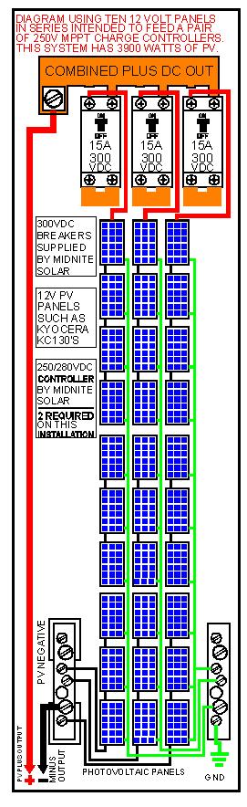
9 MNPV2, MNPV3, MNPV4, MNPV6 Instructions (continued) MNPV6-250 With (3) 300VDC Breakers installed This is a special configuration that is possible with the MidNite Solar Classic charge controller. Note that in order to use 300VDC breakers you will need the MNPV6-250 or the MNPV combiner. 300VDC breakers take up two spaces. The MNPV6-250 holds three 300VDC breakers. The MNPV holds six 300VDC breakers. Here we have 3 strings of watt panels for a total of 3900 watts Additional sample wiring diagrams and information are available at Customer Service (360) X151 7 P a g e R E V : G


10 Typical install. MNPV2, MNPV3, MNPV4, MNPV6 Instructions (continued) The picture on the right is from Lance Barker. It shows an MNPV6 with a MidNite Solar DC-GFP installed inside along with two combiner breakers. This is a novel use of the DC-GFP in the combiner enclosure. The use of din rail mount breakers makes for real flexibility. 18 trenching is reduced to 12 when a DC-GFP is on the PV end of the trench NEC article 300- wiring methods page , table minimum cover requirements, 0 to 1000 volts, burial in millimeters (inches) column 4: residential branch circuits rated 120 volts or less with GFCI protection and maximum over-current protection of 20 amps or less. Lance s inspector used the working voltage rather than max voltage in his determination. Lance was digging in a rocky area, so this trick made the job possible. You would not be allowed to reduce the trench depth if using a 200 or 250 volt controller and PV array. 4 Touch safe fuseholders installed in an MNPV6 MNPV6 and MNPV3 3 Fuse holders in deadfront shown with the fuse adapter installed Disclaimer of Liability MidNite products are not intended for use in connection with Life Support Systems. MidNite Solar makes no warranty or representation in connection with their products for such uses. Since the use of this manual and the conditions or methods of installation, operation, use of the Combiner(s) are beyond the control of MidNite Solar, this company does not assume responsibility and expressly disclaims liability for loss, damage or expense, whether direct, indirect, consequential or incidental, arising out of or anyway connected with such installation, operation, or use. MidNite Solar th Ave NE Arlington, Wa (360) P a g e R E V : G


11 MidNite Solar PV Combiners explained (MNPV) The MNPV6 PV combiner is designed to work with 6 150V breakers or 4 touch safe 600VDC fuse holders. Busbars for both configurations are included. Based on sales, this little combiner has become the favorite of the RE industry. It is the first PV combiner to come with a custom deadfront to hide wiring when the metal cover is opened. One comment we have received is that the fuse holder configuration results in a compromise when the plastic dead front is used. It is difficult to make one deadfront that works well for both scenarios. The picture below shows how the touch safe fuse holders look when used with the deadfront as compared to breakers. The breakers are a better match with the deadfront. There is a gap around touch safe fuse holders. This is not a safety issue, but rather a cosmetic one. Not wanting to have a cosmetically challenged combiner, we recently designed a snap in adapter that will be included with all MNPV3 and 6 combiners. (February or March 2009). Check out the CAD pictures here. The fuse adapters and dead fronts are actually black. The left picture has fuse holders installed.


12 The snap in adapter has notches built in to act as a guide for cutting down for MNPV3 applications. To use for MNPV3 applications, cut the large piece down to 2 or 3 spaces using a Stanley knife. The two pieces will need to be glued or taped together. Material is ABS, so common ABS pipe glue should work nicely. Snap in adapter ready for the MNPV6 combiner Snap in adapter cut down and ready to glue together for installation into the MNPV3 combiner BusBars for the MNPV3: We never thought customers would be using the MNPV3 with touch safe fuse holders. Well, we were wrong big time. These are used all the time for high voltage applications. They are used as a combiner for string inverters as well as a high voltage disconnect. The problem is that they do not come with a fuse holder busbar. Starting sometime in February 2009, the MNPV3 will come with a new internal combining busbar. The new busbar is shown below
 and cut it down for use in the MNPV3. Notice how the new MNPV3 busbar is set up for three breakers or three fuses.")
13 The new 1/8 thick copper busbar is rated for 83 amps and is reversible for use with fuses or breakers. In the past, customers would use the MNPV6 fuse busbar ($13.00 list) and cut it down for use in the MNPV3. Notice how the new MNPV3 busbar is set up for three breakers or three fuses. Each breaker is ½ wide where as the fuse holders are almost ¾ wide, thus separate finger arrangement for each application. The fact that we are putting three fuse holder fingers on the new busbar presents another problem. The MNPV3 Deadfront has three ½ knockouts. Three circuit breaker knockouts is the same width as two fuse holders. Take a close look at the back of the deadfront above. There have always been notches that would allow up to two more breakers. Now the numbers don t exactly work out perfectly for three fuse holders, but they do fit (3/4 x 3 = 2 ¼ vs. ½ x 5 = 2 ½ ). There will be a 1/8 gap on either side. The new adapter helps cover this gap somewhat though. All the MNPV3 combiners now come with a din rail that will accept up to 5 breakers, so three fuse holders is not a problem. We do not supply a busbar for more than three breakers, but the MNPV6 breaker busbar is available for $ At this point you may just want to consider the MNPV6 as it has sufficient room for more than three breakers. PV minus and ground busbars inside the MNPV6 accommodate up to 14 wires while the MNPV3 accommodate 6. By the way, don t ever open a touch safe fuse holder under load!!! The following pictures are the result of a 250 volt array that had only 5 amps flowing through it when the fuse holder was opened. This fuse holder is UL listed to 1000VDC and 30 amps. It does say Do not open under load. It s a good thing we build our combiners out of metal. The arc and fire lasted for about two full minutes until it burned out. The upcoming 250VDC MidNite Classic controller presents some problems. There will be consumers installing this high voltage controller. We highly recommend professional installation. The pictures above show a very real issue. MidNite has addressed this potential problem by creating high voltage circuit breakers and new combiners to house the new breakers. The high voltage breakers are UL listed at 250VDC. MidNite has employed ETL to conduct tests to bring the listing up to 300VDC.
14 Notice the copper plate at the bottom of the high voltage breaker. The input and output of this breaker is from the top surface. The breaker is essentially two of our 150VDC breakers in series. They are internally ganged so when one pole trips, the other also trips at the same time. It is not sufficient to handle tie two 150VDC breakers externally. They would not withstand the high voltage. High voltage arcing tends to weld internal contacts together so when you need the breaker to trip, it would in fact fuse itself in the on position. That could ruin your entire day or worse, so use the breakers that are designed for this extreme high voltage DC. The following picture shows six 300VDC breakers installed in the MNPV The large reliefs in the busbars allow PV wiring to easily enter the upper left pole of each breaker. These 168 amp busbars may be combined as shown or set up as two separate systems with three each high voltage breakers. The high voltage breakers currently stocked are 10A, 15A and 50A. Additional values are on order so check with us for available current ratings. These are very custom breakers with long lead times, so be aware not all values may be available for a while. These breakers are only available from MidNite Solar. List price for a 300VDC breaker is $ This is the regular MNPV12 combiner with the dead front and metal cover removed. In this picture the reversible busbar is combining ten touch safe fuse holders. The 200 amp busbars can be configured for up to VDC breakers or 10 fuses either separated into two systems or combined as shown. The MNPV12 and MNPV has recently passed ETL testing. Notice the picture of the MNPV12 deadfront to the right. You will notice a snap in adapter for use with fuse holders. Each combiner comes with the main large deadfront and two fuse holder adapters. This combiner with its 200 amp busbar is well equipped to handle the newer more powerful PV modules. Most existing combiners can t handle a bunch of 20 amp breakers or fuse holders. MNPV16: This new combiner has also passed ETL testing (December 08). It is intended for use with up to 16 touch safe fuse holders. The current rating is 240 amps. It can accommodate up to 250MCM output wires. There is plenty of room for PV and ground wiring. The input knockouts are concentric ½ / 7/8


15 knockouts. The ½ inner knockout can be used to install bulkhead mounted MC connectors for ease of installation at the jobsite. See pictures below. MNPV12 chassis showing concentric knockouts MNPV16 with bulkhead mount MC connectors The MNPV16 can be used with up to twenty four 150VDC circuit breakers or VDC breakers. Each version requires a different busbar arrangement, so different model numbers apply MNPV16 is for VDC fuse holders MNPV is for VDC circuit breakers MNPV is for volt breakers Go to to get wiring diagrams for each specific application. Midnite Solar th Ave NE unit C Arlington, WA USA PH: The arc here is from only 165 VDC. This arc is quenched inside the circuit breaker. A 300 VDC arc is only going to be worse. Any volunteers to run the ETL test?


16 MNPV MNPV16 WITH FUSE HOLDERS MNPV MNPV12 WITH 150VDC BREAKERS


17 MNPV6 MNPV6 MNPV6 WITH 250 BUSBARS MNPV3

18 14000 Burn Rd Arlington, WA USA Ph (425) MNPV Installation Instructions The MNPV6 combiner is rated for outdoor use. Designed for combing PV strings up to 150VDC and 120 amps total using breakers, or high voltage strings using 10mm x 38mm fuses up to 80 amps total. The use of touch safe din rail mount fuse holders and fuses allow operation up to 600 Volts. The MNPV6 combiner comes with two copper bus bars. One for circuit breakers and one for fuses. The MNPV3 busbar is designed for circuit breakers or fuses. The MNPV3 busbar is rated for 60 amps total. Applications: PV combiner up to six strings using MNPV breakers rated for 150VDC. 120 amps total output PV combining up to four strings using 600VDC fuses and MNTS touch safe fuse holders rated for 600VDC DC load center using MNPV breakers Features: All aluminum powder coated housing that won t rust Flip up cover that can stay in the open position during installation PV Negative bus bar with 14 useable openings (10 #14-6 and 4#1/0-14) Chassis ground bus bar with 14 useable openings (10 #14-6 and 4#1/0-14) Standard din rail to mount up to 6 breakers or 4 fuse holders Tin plated copper bus bar to combine breaker outputs (MNPV6 busbar may be split in two) Dead front cover snaps into place after wiring is complete for safety Knock outs for PV in and PV out on bottom and sides Top surface is available to bring conduit in from directly above the enclosure Note: The plastic dead front fits very tight. You must first remove the lid in order to remove the dead front. Rev: C Page 1 of 6

19 MNPV Installation Instructions (continued) The installation of a PV combiner is fairly straight forward. Select the location to install your combiner first. Some systems have the PV modules located close to the inverters and or battery system. If this is the case, you can elect to mount the MNPV inside and run each PV string down to the MNPV inside the house. This is convenient for trouble shooting and upgrading. For longer runs the combiner will be mounted outdoors on the pole for pole mounted PV arrays or similar mounting for rack mounted arrays. The combiner can be mounted in the vertical position or slanted backwards to accommodate up to a 3/12 roof pitch. All unused holes should be blocked using RTV sealant or some similar goop in order to keep rain and insects out of the enclosure. Care must be taken to insure that no water will get on terminal busbars when mounted less than vertical. The following dimensioned drawings show the location and size of knockouts available on the MNPV3&6. Note that on the MNPV6 the center bottom knock out is sized for a 1 1/4 conduit adapter. The left and right side each have a ½ knock out for either wire entry or for lightning arrestors. Follow directions above when using side knockouts. Lightning arrestors may require a locknut on the outside in order to clear the lid. MNPV6 & MNPV6-250 Bottom conduit locations and sizes MNPV3 bottom conduit locations Rev: C Page 2 of 6

20 MNPV Installation Instructions (continued) MNPV6 shown with breakers & lightning arrestor MNPV3 with 3 brkrs The MNPV6 enclosure can be split into two sections. This is sometimes done in 12 and 24V systems where more controllers are required for additional power. For instance in a 24 volt system using the MX60 charge controller, you are limited to about 1600 watts of PV per controller. If using Kyocera KC130 modules, you can make three strings of 4 modules in series. This adds up to 1560 watts per controller. That is a good match of PV vs. controller capability. The MNPV3 can accommodate this arrangement directly, but the MNPV6 can accommodate two of these systems, thus saving wiring, space and money. See the following figure on splitting the busbar into two systems. When selecting breakers for use with the MidNite combiners, first check with the PV manufacturer to determine the proper series fuse. The term fuse is used even though you are probably using breakers. This is a carry over from UL terminology. Rev: C Page 3 of 6
21 MNPV Installation Instructions (continued) MidNite Solar offers PV combiner breakers rated at 150VDC and 300VDC. The 150V breakers come in these amp ratings. 1,2,3,4,5,6,7,8,9,10,12, 15, 20, 30,40,50 and 63. Other sizes are available on special order. Part numbers for breakers are as follows: MNEPV10, MNEPV15, MNEPV20 etc. The 300VDC breakers are twice as wide as the 150 volt versions. The wire input and output are located on the top side. These breakers come in 7,10,12,15,20,30 and 50 amps. Part numbers are MNEPV etc. Polarity of the din rail DC breakers IMPORTANT! The DC breakers supplied by MidNite Solar are custom manufactured in Lesotho Africa by CBI. These breakers are polarity sensitive. This means that they need to be installed correctly in order to insure that they will be able to trip if called upon to do so. In a PV combiner the + sign marked on the breaker connects to the PV positive output. The same breaker when hooked up to the battery circuit (not in a PV combiner) hooks up a little different. The + sign hooks up to the battery plus. This hook up is not obvious. The + sign designates the highest potential should be connected there. This is an easy one to determine in a PV combiner. Follow the current path through the combiner, into the PV input of a charge controller and out of the controller to an output breaker and then into the battery plus. You would think that the end of the output breaker connected to the controller would be at a higher potential than the battery plus. In normal operation this is true. The main job of this output breaker is to trip when and if there is a catastrophic failure. (Any manufacture of power electronics will tell you that power electronics can fail). If the output breaker fails to trip, you are at risk of fire from the output wires burning up. When a charge controller fails, they always short from positive output to negative output. Since these two terminals inside the charge controller are normally connected up to a very large battery bank, you have a direct short across the battery bank if the controller fails. During this condition, the controller is acting like a piece of wire. The battery positive terminal is the highest potential! Make sure that the plus (line) of the breaker is connected to the battery plus terminal. If the breaker is connected backwards, it can fuse in the closed position as it attempts to open. That could ruin your entire day! The MidNite MNPV6 can also utilize touch safe fuse holders and fuses rated for up to 600 volts DC for high voltage strings. The MNPV6 comes with a special busbar that has four legs to accommodate four of these USM1 type fuse holders made by Ferraz Shawmut. Fuses are available from 1 to, 30 amps. (80 amps total) These devices are not polarity sensitive, but do not open them under load. You WILL have a fire on your hands! USM1 Fuse touch safe fuse holder Busbar, Fuse Holder The following wiring diagrams are intended to help you decide which type of combiner installation to do. There are numerous ways to hook up a PV array. There are no best or correct ways to accomplish this. They all have merit. For instance if the battery bank is 24 volts and you have six 24 volt PV modules, what Rev: C Page 4 of 6


22 MNPV Installation Instructions (continued) would be the best way to wire them? For this installation we will assume an MX60 or similar charge controller that allows the freedom to change PV array voltages. 1. This array could have all 6 panels hooked in parallel using the MNPV6 combiner and 6 MNEPV15 breakers. This array would be ok if situated close to the battery bank. It requires larger wires than higher voltage arrays, but has the advantage of temporarily directly connection to the battery bank in case the controller fails. You can also substitute a PWM controller for the MPPT in the event it becomes necessary. 2. The array could be wired in three strings of two panels in series for a 48 volt nominal array. This is a very common installation and could be made in the MNPV3 with 3 breakers. This hook up is safe from a cold VOC standpoint, but you cannot directly connect it to the battery bank. You cannot easily hook up a PWM controller either. If the PV array is between 30 and 100 feet from the battery bank, this hook up may offer the best power production. 3. The array could also be hooked up in two strings of three modules in series. The MNPV3 and two breakers will accommodate this array. You have room to grow this system without adding another combiner if only three more modules are added later. Combiners can also be combined for additional power, so if six modules or more get added later, you can simply add an additional MNPV3. When putting three 24 V modules in series you must pay attention to VOC during cold spells so that you do not over voltage the controller. MidNite Solar breakers are all rated for 150 volts DC which is higher than any present MPPT controller (2006). This configuration works very well especially when the array is far away from the battery bank. You can sometimes save enough money on reduced wire size to pay for an MPPT charge controller. To remove the dead front: Pry off the lid as shown using something like a screwdriver as a lever. The dead front will then come out easily. Rev: C Page 5 of 6


23 MNPV Installation Instructions (continued) The picture on the right is from Lance Barker. It shows an MNPV6 with a MidNite Solar DC-GFP installed inside along with two combiner breakers. This is a novel use of the DC-GFP in the combiner enclosure. The use of din rail mount breakers makes for real flexibility. 18 trenching is reduced to 12 when a DC-GFP is on the PV end of the trench NEC article 300- wiring methods page , table minimum cover requirements, 0 to 600 volts, burial in millimeters (inches) column 4: residential branch circuits rated 120 volts or less with GFCI protection and maximum over-current protection of 20 amps or less. Lance s inspector used the working voltage rather than max voltage in his determination. Lance was digging in a rocky area, so this trick made the job possible. You would not be allowed to reduce the trench depth if using a 200 or 250 volt controller and PV array. This is a special configuration that is possible with the MidNite Solar Classic charge controller. Note that in order to use 300VDC breakers you will need the MNPV6-250 or the MNPV combiner. 300VDC breakers take up two spaces. The MNPV6-250 holds three breakers. The MNPV holds six breakers. MNPV3 and MNPV6 3 Fuse holders in deadfront shown with the fuse adapter installed Fuse holders in enclosure Rev: C Page 6 of 6


24 MNPV6 Disco / MNPV6-250 MNPV6-AC Disco Installation Instructions MNPV6 Disco Shown with optional circuit breakers The MNPV6 Disco combiner is rated for outdoor use. Designed for combining PV strings up to 150VDC, 120 amps total output with the MNPV6 Disco or 300 VDC, 120 amps total output with the MNPV6-250 Disco, or 240 VAC, 120 Amps per phase with the MNPV6-AC Disco. Applications: PV combiner up to six strings using MNEPV 150 VDC breakers with the MNPV6 Disco PV combiner up to three strings using MNEPV 300 VDC breakers with the MNPV6-250 Disco AC Combiner for up to three strings for use with micro inverters using MNEAC 240 VAC Breakers DC load center using MNPV breakers Features: Convenient disconnect handle All aluminum powder coated housing that won t rust Flip up cover that can stay in the open position during installation PV Negative bus bar with 14 useable openings (10 #14-6 and 4#1/0-14) Chassis ground bus bar with 14 useable openings (10 #14-6 and 4#1/0-14) Standard din rail to mount up to 6, 150V or 3, 300 Volt breakers 120 Amp tin plated copper bus bar to combine breaker outputs - bus bar may be split in two Dead front cover snaps into place after wiring is complete for safety Knockouts for PV in and PV out on bottom and sides Top surface is available to bring conduit in from directly above the enclosure MidNite Solar inc th Ave Ne Voice Arlington, Wa USA Fax
25 MNPV6 Disco / -250 / AC Disco Installation Instructions Cont. IMPORTANT SAFETY INSTRUCTIONS SAVE THESE INSTRUCTIONS - These instructions contain important safety and operating instructions for the MidNite Solar MNPV6 Disco and MNPV6-250 Disco solar combiner boxes. If you do not fully understand any of the concepts, terminology, or hazards outlined in these instructions, please refer installation to a qualified dealer, electrician or installer. These instructions are not meant to be a complete explanation of a renewable energy system. GENERAL PRECAUTIONS WORKING WITH OR IN THE VICINITY OF A LEAD ACID BATTERY, SEALED OR VENTED IS DANGEROUS. VENTED BATTERIES GENERATE EXPLOSIVE GASES DURING NORMAL OPERATION. FOR THIS REASON, IT IS VERY IMPORTANT THAT BEFORE SERVICING EQUIPMENT IN THE VICINITY OF LEAD-ACID BATTERIES YOU REVIEW AND FOLLOW THESE INSTRUCTIONS CAREFULLY. If service or repair should become necessary, contact MidNite Solar Inc. Improper servicing may result in a risk of shock, fire or explosion. To reduce these risks, disconnect all wiring before attempting any maintenance or cleaning. Turning off the inverter will not reduce these risks. Solar modules produce power when exposed to light. When it is not possible to disconnect the power coming from the Photovoltaics by an external means such as a combiner, cover the modules with an opaque material before servicing any connected equipment. Never attempt to charge a frozen battery. When it is necessary to remove a battery, make sure that the battery bank disconnect breaker is in the off position and that the PV breakers, grid breakers and any other sources of power to the inverter are in the off position. Then remove the negative terminal from the battery first. To reduce risk of battery explosion follow these instructions and those published by the battery manufacturer as well as the manufacturer of any additional equipment used in the vicinity of the batteries. Before installing the battery enclosure, read all instructions and cautionary markings in or on any connected electrical equipment. Avoid producing sparks in the vicinity of the batteries when using vented batteries. Provide ventilation to clear the area of explosive gases. Sealed AGM and Gel batteries do not under normal conditions create explosive gases. Be especially cautious when using metal tools. Dropping a metal tool onto batteries can short circuit them. The resulting spark can lead to personal injury or damage to the equipment. Provide ventilation to outdoors from the battery compartment when installing vented batteries such as golf cart T-105 batteries. The addition of a spill tray is also a good idea. Clean all battery terminals. Very high currents are drawn from the batteries; even a small amount of electrical resistance can result in overheating, poor performance, premature failure or even fire. Have plenty of fresh water and soap nearby in case battery acid contacts skin, clothing or eyes. Wear complete eye and clothing protection. Always avoid touching eyes while working near batteries. If battery acid or battery terminal corrosion contacts skin or clothing, wash immediately with soap and water. If acid enters the eyes, immediately flood with cool running water for at least 15 minutes and get medical attention immediately. Baking soda neutralizes battery acid electrolyte. Keep a supply near the batteries. Do not work alone. Someone should be in the range of your voice or close enough to come to your aid when you work with or near electrical equipment. Remove rings, bracelets, necklaces, watches etc. when working with batteries, photovoltaic modules or other electrical equipment. Power from an illuminated photovoltaic array makes a very effective arc welder with dire consequences if one of the welded pieces is on your person. To reduce the risk of injury, connect only deep cycle lead acid type rechargeable batteries. Other types of batteries may leak or burst, causing personal injury or damage. 2 P a g e R E V : B

26 MNPV6 Disco / -250 / AC Disco Installation Instructions Cont. Installation The installation of a PV combiner is fairly straight forward. Select the location to install your combiner first. Some systems have the PV modules located close to the inverters and or battery system. If this is the case, you can elect to mount the MNPV6 Disco / MNPV6-250 Disco inside and run each PV string down to the MNPV6 Disco / MNPV6-250 Disco inside the house. This is convenient for trouble shooting and upgrading. For longer runs the combiner will be mounted outdoors on the pole for pole mounted PV arrays or similar mounting for rack mounted arrays. The combiner can be mounted in the vertical position or slanted backwards to accommodate up to a 3/12 roof pitch. All unused holes should be blocked using RTV sealant or some similar goop in order to keep rain and insects out of the enclosure. Care must be taken to insure that no water will get on terminal busbars when mounted less than vertical. The following dimensioned drawings show the location and size of knockouts available on the MNPV6 Disco / MNPV6-250 Disco. Note that on the MNPV6 Disco the center bottom knock out is sized for a 1 1/4 conduit adapter. The left and right side each have a ½ knock out for either wire entry or for lightning arrestors. Follow directions above referring to rain and insects when using side knockouts to keep water off terminal busbars. Lightning arrestors may require a locknut on the outside in order to clear the lid ( 1 2" KO) Ø0.89 Ø0.50 (FOR BULKHEAD MOUNT MC CONNECTORS Ø1.75 (1 1 4" KO) MNPV6 Disco Bottom conduit locations and sizes (not to scale) Note: The plastic dead front fits very tight. You must first remove the lid in order to remove the deadfront. Remove the deadfront: Pry off the lid as shown using something like a screwdriver as a lever. The dead front will then come out easily. 3 P a g e R E V : B

27 MNPV6 Disco / -250 / AC Disco Installation Instructions Cont. Handle Installation To avoid possible damage to the combiner parts it is important to follow these instructions carefully. 1. Turn off breakers. 2. Move handle to the off position. 3. Orient the grabber as shown. 4. Close cover. Do not use force. With the breakers and the handle in the Off position, place the grabber into the opening In the handle where shown (Photo right and image on slider). Ensure that the grabber lines up with the rail on the circuit breaker slider. Check for proper actuation by moving the handle and listening for the breakers. Grabber Slider The MNPV6 Disco s busbar can be split into two sections making the MNPV6 Disco equivalent to 2 MNPV3 combiners in one. This is sometimes done in 12 and 24V systems where more controllers are required for additional power. For instance in a 24 volt system using a 60 amp charge controller, you are limited to about 1600 watts of PV per controller. If using Kyocera KC130 modules, you can make three strings of 4 modules in series. This adds up to 1560 watts per controller. That is a good match of PV vs. controller capability. The MNPV3 can accommodate this arrangement directly, but the MNPV6 Disco can accommodate two of these systems, thus saving wiring, space and money. See the following figure on splitting the busbar into two systems. Busbar for 300VDC Breakers. (MNPV6-250 Disco) 300 VDC breakers take up two spaces and require a larger busbar. Install the busbar into the connection marked - on the breakers. 4 P a g e R E V : B
28 MNPV6 Disco / -250 / AC Disco Installation Instructions Cont. Circuit breaker selection. When selecting breakers for use with the MidNite combiners, first check with the PV manufacturer to determine the proper series fuse. The term fuse is used even though you are probably using breakers. This is a carryover from UL terminology. MidNite Solar offers PV combiner breakers rated at 150VDC, 300VDC and 240 VAC. 150V DC breakers come in these amperage ratings. 1, 2, 3, 4, 5, 6, 7, 8, 9, 10, 12, 15, 20, 30, 40, 50, 60 and 63. Part numbers for breakers are as follows: MNEPV10, MNEPV15, MNEPV20 etc, the last 2 digits being the amperage rating of the breaker. 300VDC breakers are twice as wide as the 150 volt versions. The wire input and output are located on the top side. These breakers come in 7,10,12,15,20,30 and 50 amp sizes. Part numbers are MNEPV etc. Other sizes are available on special order. AC breakers come in 10, 15, 20, 30, 40, 50 and 60 amp sizes. Part numbers for AC breakers are as follows: MNEAC10, MNEAC20-2P etc. IMPORTANT! Polarity of the din rail DC breakers. The DC breakers supplied by MidNite Solar are custom manufactured in Lesotho Africa by CBI. These breakers, like many other DC breakers are polarity sensitive. This means that they need to be installed correctly in order to insure that they will be able to trip if called upon to do so. In a PV combiner the + sign marked on the breaker connects to the PV positive output. The same breaker when hooked up to the battery circuit (not in a PV combiner) hooks up a little different. The + sign hooks up to the battery plus. This hook up is not obvious. The + sign designates the highest potential should be connected there. This is an easy one to determine in a PV combiner. Follow the current path through the combiner, into the PV input of a charge controller and out of the controller to an output breaker and then into the battery plus. You would think that the end of the output breaker connected to the controller would be at a higher potential than the battery plus. In normal operation this is true. The main job of this output breaker is to trip when and if there is a catastrophic failure. (Any manufacturer of power electronics will tell you that power electronics can fail). If the output breaker fails to trip, you are at risk of fire from the output wires burning up. When a charge controller fails, they always short from positive output to negative output. Since these two terminals inside the charge controller are normally connected up to a very large battery bank, you have a direct short across the battery bank if the controller fails. During this condition, the controller is acting like a piece of wire. The battery positive terminal is the highest potential! Make sure that the plus (line) of the breaker is connected to the battery plus terminal. If the breaker is connected backwards, it can fuse in the closed position as it attempts to open. That could ruin your entire day! Combiner wiring. There are numerous ways to hook up a PV array. There are no best or correct ways to accomplish this. They all have merit. For instance if the battery bank is 24 volts and you have six 24 volt PV modules, what would be the best way to wire them? For this installation we will assume a Classic 150 or similar charge controller that allows the freedom to change PV array voltages. 1. This array could have all 6 panels hooked in parallel using the MNPV6 combiner and 6 MNEPV15 breakers. This array would be ok if situated close to the battery bank. It requires larger wires than would a higher voltage array, but has the advantage of being directly connected to the battery bank in case the controller fails. You can also substitute a PWM controller for the MPPT in the event it becomes necessary. 2. The array could be wired in three strings of two panels in series for a 48 volt nominal array. This is a very common installation and could be made with 3 breakers. This hook up is safe from a cold VOC standpoint, but you cannot directly connect it to the battery bank. You cannot easily hook up a PWM controller either. If the PV array is between 30 and 100 feet from the battery bank, this hook up may offer the best power production. 3. The array could also be hooked up in two strings of three modules in series. The MNPV6 disco / MNPV6-250 Disco and two breakers would accommodate this array. You have room to grow this system without adding 5 P a g e R E V : B

29 MNPV6 Disco / -250 / AC Disco Installation Instructions Cont. another combiner. Combiners can also be combined for additional power, so if more modules are added later, you can simply add an additional combiner. When putting three 24 V modules in series you must pay attention to VOC during cold spells so that you do not over voltage the controller. MidNite Solar breakers are rated for 150 and 300VDC. This configuration works very well especially when the array is far away from the battery bank. You can sometimes save enough money on reduced wire size to pay for an MPPT charge controller. The following wiring diagrams are intended to help you decide which type of combiner installation to do. Above left: MNPV6 Disco wired with a split bus bar. A basic wiring diagram is located inside the top cover of the combiner. Additional wiring diagrams are available at in AutoCad format. These diagrams may be downloaded and modified to represent a specific installation. Torque - Circuit Breaker QY Circuit breakers 150 or 300 V 20 in-lbs (2.3Nm) Important! Re-Torque to 20 in-lbs (2.3Nm) after 1 hour. Torque Terminal Bus Bar 10AWG 20 in-lbs (2.3Nm) 8AWG 25 in-lbs (2.8Nm) 6AWG 35 in-lbs (4.0Nm) 4AWG 45 in-lbs (5.1Nm) 2AWG 1/0 50 in-lbs (5.6Nm) Above right is a special configuration that is possible with the MidNite Solar Classic charge controller. The MNPV6-250 Disco holds three 300VDC breakers. 300VDC breakers take up two spaces. Here we have 3 strings of watt panels for a total of 3900 watts. Note that PV input and combined output are both wired to the top side of the breaker. Observe polarity as noted above. 6 P a g e R E V : B
30 MNPV6 Disco / -250 / AC Disco Installation Instructions Cont. L1 ON ON ON ON ON ON L2 OFF OFF OFF OFF OFF OFF 20A 20A 20A 20A 20A 20A L2 L1 L2 L1 L2 L1 Ground Neutral Combined Out In from micro inverters 7 P a g e R E V : B MNPV6 Disco Wired as a three position AC Combiner for Micro Inverters
31 MNPV6 Disco / -250 / AC Disco Installation Instructions Cont. MIDNITE SOLAR INC. LIMITED WARRANTY MidNite Solar Power electronics, sheet metal enclosures and accessories MidNite Solar Inc. warrants to the original customer that its products shall be free from defects in materials and workmanship. This warranty will be valid for a period of five (5) years for all products except the MNKID Charge Controller which will be two (2) years. At its option, MidNite Solar will repair or replace at no charge any MidNite product that proves to be defective within such warranty period. This warranty shall not apply if the MidNite Solar product has been damaged by unreasonable use, accident, negligence, service or modification by anyone other than MidNite Solar, or by any other causes unrelated to materials and workmanship. The original consumer purchaser must retain original purchase receipt for proof of purchase as a condition precedent to warranty coverage. To receive in-warranty service, the defective product must be received no later than two (2) weeks after the end of the warranty period. The product must be accompanied by proof of purchase and Return Authorization (RA) number issued by MidNite Solar. For an RMA number contact MidNite Solar Inc., th Ave NE, Arlington, WA (360) Purchasers must prepay all delivery costs or shipping charges to return any defective MidNite Solar product under this warranty policy. Except for the warranty that the products are made in accordance with, the specifications therefore supplied or agreed to by customer: MIDNITE SOLAR MAKES NO WARRANTY EXPRESSED OR IMPLIED, AND ANY IMPLIED WARRANTY OF MERCHANTABILITY OR FITNESS FOR A PARTICULAR PURPOSE WHICH EXCEEDS THE FOREGOING WARRANTY IS HEREBY DISCLAIMED BY MIDNITE SOLAR AND EXCLUDED FROM ANY AGREEMENT MADE BY ACCEPTANCE OF ANY ORDER PURSUANT TO THIS QUOTATION. MIDNITE SOLAR WILL NOT BE LIABLE FOR ANY CONSEQUENTIAL DAMAGES, LOSS OR EXPENSE ARISING IN CONNECTION WITH THE USE OF OR THE INABILITY TO USE ITS GOODS FOR ANY PURPOSE WHATSOEVER. MIDNITE SOLAR S MAXIMUM LIABILITY SHALL NOT IN ANY CASE EXCEED THE CONTRACT PRICE FOR THE GOODS CLAIMED TO BE DEFECTIVE OR UNSUITABLE. Products will be considered accepted by customer unless written notice to the contrary is given to MidNite Solar within ten (10) days of such delivery to customer. MIDNITE SOLAR is not responsible for loss or damage to products owned by customer and located on MIDNITE SOLAR S premises caused by fire or other casualties beyond MIDNITE SOLAR s control. This warranty is in lieu of all other warranties expressed or implied. MIDNITE SOLAR INC TH AVE NE ARLINGTON, WA info@midnitesolar.com PH: FAX: P a g e R E V : B


 MNPV2-MC4 two strings, MNPV3 two strings with fuses, three strings with 150 volt breakers Powder coated aluminum with stainless")


32 MidNite Solar s S s PV Combiners MidNite Solar offers a range of PV Combiners from our MNPV3 to the MNPV12v. This range of combiners accommodates PV systems as small as a two string off grid cabin up to 12 strings for a 50KW commercial grid tie inverter MNPV2-MC4 and MNPV3 MNPV8-MC4, MNPV12 and MNPV Enclosure rating Outdoor Rainproof NEMA 3R Outdoor Rainproof NEMA 3R Outdoor Rainproof NEMA 3R Enclosure material Mounting options and angle Number of PV strings Maximum number of output circuits Wire range for string input Maximum OCPD rating MNPV2-MC4 and MNPV3 Powder coated aluminum with stainless hardware Vertical wall mount, pole mount or sloped roof mount to 14 degrees incline (3 in 12 roof pitch) MNPV2-MC4 two strings, MNPV3 two strings with fuses, three strings with 150 volt breakers Powder coated aluminum with stainless hardware Vertical wall mount, pole mount or sloped roof mount to 14 degrees incline (3 in 12 roof pitch) MNPV4-MC4 four strings, MNPV6 four strings with fuses, six strings with 150 volt breakers, MNPV6-250 three strings with 300 volt breakers 1 for all MNPV4-MC4 and MNPV6 is two, MNPV6-250 is one MNPV2-MC4 NA uses MC4 connectors, MNPV AWG 30 amp with fuses and 63 amps with 150 volt breakers MNPV4-MC4, MNPV6 and MNPV6-250 MidNite Solar PV Combiner Specifications MNPV4-MC4, MNPV6 and MNPV6-250 MNPV4-MC4 NA uses MC4 connectors MNPV6 and MNPV AWG 30 amp with fuses, 63 amps with 150 volt breakers and 50 amps with 300 volt breakers MNPV8-MC4, MNPV12 and MNPV Powder coated aluminum with stainless hardware Vertical wall mount, pole mount or sloped roof mount to 14 degrees incline (3 in 12 roof pitch) MNPV8-MC4 four strings MNPV12 eight strings with fuses and twelve strings with 150 volt breakers MNPV six strings with 300 volt breakers 2 for all MNPV8-MC4 NA uses MC4 connectors MNPV12 and MNPV AWG 30 amp with fuses, 63 amps with 150 volt breakers and 50 amps with 300 volt breakers Maximum output amps 60 amps for all 80 amps for fused, 120 amp for breakers 200 Amps with Fuses and 150 volt breakers, 168 amps with 300 volt breakers Output wire range 14 to 1/0 AWG 14 to 1/0 AWG 14 to 1/0 AWG Lug temperature rating 90 deg C 90 deg C 90 deg C Deadfront Custom molded plastic deadfront Custom molded plastic deadfront Custom molded plastic deadfront Lockable Yes Yes Yes Rating UL1741 UL1741 UL th Ave NE Arlington, n WA PH FAX
MNPV Installation Instructions
 14000 Burn Rd Arlington, WA 98223 USA Ph (425)374-9060 www.midnitesolar.com MNPV Installation Instructions The MNPV6 combiner is rated for outdoor use. Designed for combining PV strings up to 150VDC and
MNPV2, MNPV3, MNPV4, MNPV6 Instructions
 MNPV2, MNPV3, MNPV4, MNPV6 Instructions The MNPV6 combiner is rated for outdoor use. Designed for combining PV strings up to 150VDC and 120 amps total using breakers, or high voltage strings up to 1000VDC
SAVE THESE INSTRUCTIONS
 MNPV12 & 16 Combiner Instructions Applications: SAVE THESE INSTRUCTIONS PV combiner up to 16 strings using MNPV breakers rated for 150VDC. 120 amps total output PV combiner up to 12 strings using 600VDC
SAVE THESE INSTRUCTIONS
 MNPV10, MNPV12 Combiner Applications: SAVE THESE INSTRUCTIONS PV combiner up to 12 strings using MNPV breakers 1000 VDC Combiner using MNTS touch safe fuse holders and fuses rated for 1000VDC DC load center
MNPV6 Disco / MNPV6-250 MNPV6-AC Disco Installation Instructions
 MNPV6 Disco / MNPV6-250 MNPV6-AC Disco Installation Instructions MNPV6 Disco Shown with optional circuit breakers The MNPV6 Disco combiner is rated for outdoor use. Designed for combining PV strings up
Battery Enclosure Installation Instructions
 MNBE-C Battery Enclosure Instructions Battery Enclosure Installation Instructions MNBE-C These instructions are for the installation of Midnite Solar Battery Enclosure models MNBE-C, MNBE-CL16 and MNBE-C8D
MNDC-X2 INSTRUCTIONS
 MNDC-X2 INSTRUCTIONS Models: MNDC125-X2, MNDC175-X2, MNDC250-X2 The MNDC125-X2 Based on our Narrow E-Panel chassis and MNDC175-X2 and MNDC250-X2 based on our wide E-Panel chassis with a blank door the
Magnum AC Coupled In a D3R battery box MND3RACCPLME 7/20/18
 Magnum AC Coupled In a D3R battery box MND3RACCPLME 7/20/18 SAVE THESE INSTRUCTIONS - These instructions contain important safety and operating instructions for the MidNite Solar Battery Enclosure Size
MNPVHV Disco Installation Instructions
 MNPVHV Disco Installation Instructions MNPV8HV TYPE 4X MNPV8HV TYPE 3R The MNPVHV combiners are rated for outdoor use. Designed for combining high voltage strings using 10mm x 38mm fuses. The use of touch
XW E-Panel installation manual
 14000 Burn Rd Arlington, WA 98223 USA Ph (425)374-9060 www.midnitesolar.com XW E-Panel installation manual Model MNE250XW The MidNite Solar XW E-Panel is designed for a single XW inverter installation.
MASTERsine Inverter PXA Series Installation Guide
 Backup Power System Expert TM MASTERsine Inverter PXA Series Installation Guide Important Safety Instructions IMPORTANT: Read and save this Installation Guide for future reference. This chapter contains
MODEL 6010A 6 12 VOLT BATTERY CHARGER ASSOCIATE
 MODEL 600A 6 VOLT BATTERY CHARGER ASSOCIATE IMPORTANT SAFETY INSTRUCTIONS. SAVE THESE INSTRUCTIONS. This manual contains important safety and operating instructions for the battery charger you have purchased.
AUTO CHARGE DUAL MODEL #: AUTOMATIC DUAL OUTPUT BATTERY CHARGER INSTRUCTION MANUAL. Ph: Fax:
 INSTRUCTION MANUAL AUTO CHARGE DUAL AUTOMATIC DUAL OUTPUT BATTERY CHARGER MODEL #: 091-145-12 INPUT: 120 Volt, 50/60 Hz, 3.5 Amps OUTPUT BAT 1: 10 Amps OUTPUT BAT 2: 10 Amps File: IM_091-145-12_revb.indd
LESTRONIC II BATTERY CHARGER MODEL 07210
 LESTRONIC II BATTERY CHARGER MODEL 07210 PLEASE SAVE THESE IMPORTANT SAFETY AND OPERATING INSTRUCTIONS For correct operation of the equipment, it is important to read and be familiar with this entire manual
 Retail Price list December, 2007 NOTE: ALL E-PANELS HAVE SWITCHED TO LEFT HAND HINGE AS THE STANDARD E-Panel, OutBack version ETL listed for the US and Canada Model No. Price Description shipping Size
AUTO CHARGE D2 MODEL #: AUTOMATIC TRIPLE OUTPUT BATTERY CHARGER INSTRUCTION MANUAL
 INSTRUCTION MANUAL AUTO CHARGE D2 AUTOMATIC TRIPLE OUTPUT BATTERY CHARGER Designed Specifically for Vehicles with DDEC ENGINES MODEL #: 091-74-12 INPUT: 120 Volt, 60 Hz, 8 Amps OUTPUT VEHICLE BATTERY 1
AUTO CHARGE 11 MODEL #: XX. AUTOMATIC BATTERY CHARGER U.L. Configuration INSTRUCTION MANUAL
 INSTRUCTION MANUAL AUTO CHARGE 11 AUTOMATIC BATTERY CHARGER U.L. Configuration MODEL #: 091-11-XX NOTE : This charger is designed for vehicles with dual batteries and negative ground. CAUTION This unit
AUTO CHARGE D PUMP PLUS
 INSTRUCTION MANUAL AUTO CHARGE D PUMP PLUS AUTOMATIC DUAL OUTPUT BATTERY CHARGER Designed Specifically for Vehicles with DDEC ENGINES MODEL #: 091-9-DPP INPUT: 120 Volt, 60 Hz, 8 Amps OUTPUT VEHICLE BATTERY:
AUTO CHARGE 12 HO MODEL #: MODEL #: MODEL #: AUTOMATIC SINGLE OUTPUT BATTERY CHARGER INSTRUCTION MANUAL
 INSTRUCTION MANUAL AUTO CHARGE 12 HO AUTOMATIC SINGLE OUTPUT BATTERY CHARGER MODEL #: 091-170-6 MODEL #: 091-170-12 MODEL #: 091-170-24 File: IM_091-170-xx_revd.indd Rev: D Revised By: MFG Date: 10-23-2013
OPERATOR'S MANUAL IMPORTANT SAFETY INSTRUCTIONS
 ASSOCIATED OPERATOR'S MANUAL IMPORTANT SAFETY INSTRUCTIONS MODEL 6366 12 VOLT, 0-20 AMP 4 X 20 BATTERY CHARGER 1. SAVE THESE INSTRUCTIONS. This manual contains important safety and operating instructions
BATTERY SAVER LOW RIPPLE HO
 INSTRUCTION MANUAL BATTERY SAVER LOW RIPPLE HO LOW RIPPLE POWER SUPPLY / AUTOMATIC LOAD SWITCH FOR 12VDC VEHICLE SYSTEMS MODEL #: 091-195-12 INPUT: 120 Volt, 50/60 Hz, 4.5 Amps RMS OUTPUT: 13.2 Volts DC,
Cruising Charger Series OWNER S MANUAL
 R Cruising Charger Series OWNER S MANUAL ON BOARD BATTERY CHARGERS Models DC Amperage No. Of Banks Volts 2614A 5,10 Amps 2 Bank 12/12 2614A-230 2621A 5,5,10 Amps 3 Banks 12/12/12 2621A-230 2622A 10,10
LPC 20 MODEL #: LOW PROFILE CHARGER AUTOMATIC SINGLE OUTPUT BATTERY CHARGER INSTRUCTION MANUAL
 INSTRUCTION MANUAL LPC 20 LOW PROFILE CHARGER AUTOMATIC SINGLE OUTPUT BATTERY CHARGER Unit supplied with one of these displays MODEL #: 091-207-12 INPUT: 120 Volt, 50/60 Hz, 7 Amps OUTPUT: 20 Amps File:
AUTO CHARGE 12 AUTOMATIC BATTERY CHARGER
 INSTRUCTION MANUAL FILE: 091-165-12 reve Rev: E, page 8 DATE: 7-02-15 AUTO CHARGE 12 AUTOMATIC BATTERY CHARGER MODEL #091-165-12 NOTE : This charger is designed for vehicles with a single battery and negative
AUTO CHARGE 4000 MODEL #: LOW PROFILE CHARGER AUTOMATIC DUAL OUTPUT BATTERY CHARGER INSTRUCTION MANUAL
 INSTRUCTION MANUAL AUTO CHARGE 4000 LOW PROFILE CHARGER AUTOMATIC DUAL OUTPUT BATTERY CHARGER Unit supplied with this display MODEL #: 091-89-12 INPUT: 120 Volt, 50/60 Hz, 5 Amps OUTPUT: 45 Amps File:
AUTO CHARGE 4000 MODEL #: AUTOMATIC DUAL OUTPUT BATTERY CHARGER INSTRUCTION MANUAL. Ph: Fax:
 INSTRUCTION MANUAL AUTO CHARGE 4000 AUTOMATIC DUAL OUTPUT BATTERY CHARGER MODEL #: 091-89-12 INPUT: 120 Volt, 50/60 Hz, 8 Amps OUTPUT BATTERY CHARGER: 40 Amps OUTPUT BATTERY SAVER: 5 Amps File: IM_091-89-12_reve.indd
AUTOMATIC BEST BATTERY SELECTOR INSTALLATION & OPERATION BBS-4800 BBS-4800E
 AUTOMATIC BEST BATTERY SELECTOR INSTALLATION & OPERATION BBS-4800 BBS-4800E SENS part no: 101312 Document revision: K DCN No. 107455 Date 4/2/18 1840 Industrial Circle Longmont, CO 80501 Fax: (303) 678-7504
Clipper Instructions
 Clipper Instructions The MNCLIPPER works alone or with the MidNite Solar Classic MPPT Charge Controller to provide the highest level of performance and protection possible. Features: Helps protect turbine
MODEL 6017 OPERATOR'S MANUAL
 MODEL 6017 OPERATOR'S MANUAL ASSOCIATE D IMPORTANT SAFETY INSTRUCTIONS 1. SAVE THESE INSTRUCTIONS. This manual contains important safety and operating instructions for the battery charger you have purchased.
LESTRONIC II BATTERY CHARGER MODEL 19740
 *01679* LESTRONIC II BATTERY CHARGER MODEL 19740 PLEASE SAVE THESE IMPORTANT SAFETY AND OPERATING INSTRUCTIONS For correct operation of the equipment, it is important to read and be familiar with this
SunLink PV System Disconnect with Arc Fault Detection Installation and Operations Manual
 Combiner Box Installation & Operations Manual SunLink PV System Disconnect with Arc Fault Detection Installation and Operations Manual TABLE OF CONTENTS Notices and Safety Precautions Pages 1-2 Combiner
PUMP PLUS 2000 PLC MODEL #: PP AUTOMATIC DUAL OUTPUT BATTERY CHARGER INSTRUCTION MANUAL
 INSTRUCTION MANUAL PUMP PLUS 2000 PLC AUTOMATIC DUAL OUTPUT BATTERY CHARGER Supplied with Dual Bar Graph Display MODEL #: 091-237-12-PP INPUT: 120 Volt, 60 Hz, 3.5 Amps OUTPUT BATTERY 1 and 2: 15 or 18
MNBRATKIT MidNite Brat Solar Charging Kit
 1 pc MNBRAT 20/30-amp PWM Charge Controller 1 pc MNBIGBABY Breaker Box 3 pcs 1-10A 1-20A 1-30A MNEPV- PV, Battery and Load Breakers 2 pcs 2 pcs 9-161-1 Strain Relief 9-162-1 Lock Nut 2-4 Hole Strain Reliefs
INSTRUCTION MANUAL. 12-Station HD Shop 12V Portable Battery Charger
 INSTRUCTION MANUAL 12-Station HD Shop 12V Portable Battery Charger IMPORTANT SAFETY INSTRUCTIONS 1. SAVE THESE INSTRUCTIONS This manual contains important safety and operating instructions for your HD
12V 1 AMP (1000 ma) Automatic Battery Charger & Maintainer
 Automatic Battery Charger & Maintainer") 12V 1 AMP (1000 ma) Automatic Battery Charger & Maintainer For lead-acid batteries THIS MANUAL CONTAINS IMPORTANT SAFETY AND OPERATING INSTRUCTIONS FOR 12V BATTERY CHARGER: YUA1201000 / INT1201000 KEEP
12V 1 AMP (1000 ma) Automatic Battery Charger & Maintainer For lead-acid batteries THIS MANUAL CONTAINS IMPORTANT SAFETY AND OPERATING INSTRUCTIONS FOR 12V BATTERY CHARGER: YUA1201000 / INT1201000 KEEP
LESTRONIC II BATTERY CHARGER BUILT-IN OR PORTABLE CHARGERS
 LESTRONIC II BATTERY CHARGER BUILT-IN OR PORTABLE CHARGERS PLEASE SAVE THESE IMPORTANT SAFETY AND OPERATING INSTRUCTIONS For correct operation of the equipment, it is important to read and be familiar
2017 Clearance Sale. Updated
 2017 Clearance Sale SunWize Power and Battery has overstock and older inventory that needs to find a new home. All items are limited to stock on hand and are subject to prior sale. All Sales are final,
PUMP PLUS 1000 PLC MODEL #: PP AUTOMATIC SINGLE OUTPUT BATTERY CHARGER INSTRUCTION MANUAL
 INSTRUCTION MANUAL PUMP PLUS 1000 PLC AUTOMATIC SINGLE OUTPUT BATTERY CHARGER Unit supplied with one of these displays MODEL #: 091-215-12-PP INPUT: 120 Volt, 60 Hz, 3.5 Amps OUTPUT BATTERY 1 and 2: 15
2/10/50 AMP 12 VOLT BATTERY CHARGER/ ENGINE STARTER
 2/10/50 AMP 12 VOLT BATTERY CHARGER/ ENGINE STARTER WARNING This product contains or, when used, produces a chemical known to the State of California to cause cancer and birth defects or other reproductive
SAVE THESE INSTRUCTIONS
 R MODEL 2611 10 AMP ON BOARD BATTERY CHARGER Two Outputs OWNER S MANUAL Connections at a glance: For the best charging results both 12 Volt independent batteries should be equally discharged. The charger
Safety, Installation And Operating Instructions For The Following Battery Charger Models: i2412, i3612, i4809, i2425, i3625, and i4818
 Safety, Installation And Operating Instructions For The Following Battery Charger Models: i2412, i3612, i4809, i2425, i3625, and i4818 IMPORTANT NOTICE: Please save and read these safety, operating and
AC CONVERTER / BATTERY CHARGER
 AC CONVERTER / BATTERY CHARGER User s Manual MODEL #: CON120AC12/24VDC Listed to UL 458 and CSA 22.2 NO. 107.1 Standards Contents INTRODUCTION... 3 Important Safety Instructions... 3 1. General Description...
Model: SE-4020-CA Automatic Battery Charger
 OWNERS MANUAL Model: SE-4020-CA Automatic Battery Charger PLEASE SAVE THIS OWNERS MANUAL AND READ BEFORE EACH USE. This manual will explain how to use the battery charger safely and effectively. Please
Sentry Battery Charger. Installation and Operations Manual Section 75
 Sentry Battery Charger Installation and Operations Manual 00-02-0616 03-03-08 Section 75 In order to consistently bring you the highest quality, full featured products, we reserve the right to change our
801 BUSINESS CENTER DRIVE MOUNT PROSPECT, ILLINOIS
 280-600 Send Warranty Product Repairs to: 1025 E. Thompson Ave., Hoopeston, IL 60942-0280. Call Customer Service if you have questions: 1-800-621-5485 A. IMPORTANT SAFETY INSTRUCTIONS 1. SAVE THESE INSTRUCTIONS
MODEL A96 SERIES. 130Vdc Switchmode Utility Rectifier / Battery Charger. Used with LaMarche Power Cage ECN/DATE
 MODEL A96 SERIES 130Vdc Switchmode Utility Rectifier / Battery Charger Used with LaMarche Power Cage CPN112138 ECN/DATE ISSUE DATE: ECN 17010-12/05 106 BRADROCK DRIVE DES PLAINES, IL. 60018-1967 (847)
Installation and Operating Instructions (for chargers shown below)
") Installation and Operating Instructions (for chargers shown below) For additional information please call our Technical Support Group 800.742.2740 PRO CHARGING SYSTEMS, LLC 1551 Heil Quaker Boulevard,
Installation and Operating Instructions (for chargers shown below) For additional information please call our Technical Support Group 800.742.2740 PRO CHARGING SYSTEMS, LLC 1551 Heil Quaker Boulevard,
LPC 40 MODEL #: LOW PROFILE CHARGER WITH PLC AUTOMATIC SINGLE OUTPUT BATTERY CHARGER INSTRUCTION MANUAL
 INSTRUCTION MANUAL LPC 40 LOW PROFILE CHARGER WITH PLC AUTOMATIC SINGLE OUTPUT BATTERY CHARGER Unit supplied with one of these displays MODEL #: 091-200-12 INPUT: 120 Volt, 50/60 Hz, 5 Amps OUTPUT: 40
10 AMP ON BOARD BATTERY CHARGER
 R A Valley Forge Company MODEL 2611A-1-B 10 AMP ON BOARD BATTERY CHARGER One Output OWNER S MANUAL IMPORTANT! READ THESE INSTRUCTIONS BEFORE INSTALLING AND USING THIS PRODUCT. Keep these instructions for
PSJ-2212, PSJ-3612, PSJ-4424
 Model: PSJ-2212, PSJ-3612, PSJ-4424 Jump Starter and DC Power Source OWNER S MANUAL PSJ-2212 PLEASE SAVE THIS OWNER S MANUAL AND READ BEFORE EACH USE. This manual will explain how to use your jump starter
AUTOMATIC BEST BATTERY SELECTOR INSTALLATION & OPERATION BBS-1600 BBS-1600E
 AUTOMATIC BEST BATTERY SELECTOR INSTALLATION & OPERATION BBS-1600 BBS-1600E SENS part no: 101314 Document revision: H DCN No. 107395 Date 11/22/17 1840 Industrial Circle Longmont, CO 80501 Fax: (303) 678-7504
Off Grid Residential Package 1.0KW
 Off Grid Residential Package 1.0KW List Price: $12,876.63 Our Price: $11,545.59 Save: $1,331.04 (10%) Model: Off-Grid Res Pkg 1kW Our Code: KITOFFGRID-B This item is a package made up of the following
801 BUSINESS CENTER DRIVE MOUNT PROSPECT, ILLINOIS Ext. 322
 277-999 ELECTRIC CORP. 801 BUSINESS CENTER DRIVE MOUNT PROSPECT, ILLINOIS 800-621-5485 Ext. 322 Send Warranty Product Repairs to: 605 South Vermilion, Suite C, Brownsville, TX 78521-6851 Call Customer
MODEL 2602A-12 3 STAGE AUTOMATIC BATTERY CHARGER OWNER S MANUAL SAVE THESE INSTRUCTIONS
 R A Valley Forge Company MODEL 2602A-12 3 STAGE AUTOMATIC BATTERY CHARGER OWNER S MANUAL SAVE THESE INSTRUCTIONS 1. INTRODUCING THE CHARGER The 2602A-12 is a 3-stage electronic battery charger. Rainproof,
A48 / A48B (base plate) BATTERY CHARGER
 BATTERY CHARGER") A48 / A48B (base plate) BATTERY CHARGER CPN41054 ISSUE DATE: 12315-8/98 ECN/DATE 106 BRADROCK DRIVE DES PLAINES, IL. 60018-1967 (847) 299-1188 FAX: (847)299-3061 15349-07-07/02 16041 6/03 14575-2/01 INSTRUCTION
A48 / A48B (base plate) BATTERY CHARGER CPN41054 ISSUE DATE: 12315-8/98 ECN/DATE 106 BRADROCK DRIVE DES PLAINES, IL. 60018-1967 (847) 299-1188 FAX: (847)299-3061 15349-07-07/02 16041 6/03 14575-2/01 INSTRUCTION
INTELLIGENT BATTERY CHARGER/MAINTAINER
 INTELLIGENT BATTERY CHARGER/MAINTAINER OWNER S MANUAL Read carefully and understand all ASSEMBLY AND OPERATION INSTRUCTIONS before operating. Failure to follow the safety rules and other basic safety precautions
E-Panel Instructions. Regular (narrow) OutBack E-Panel parts. OutBack E-Panel as installed (narrow)
 OutBack E-Panel parts. OutBack E-Panel as installed (narrow)") E-Panel Instructions Model: MNE125ST, MNE175ST, MNE250ST, MNE125AL, MNE175AL, MNE250AL, MNE175STS, MNE250STS, MNE125LT, MNE175LT, MNE250LT, MNE125ALT, MNE175ALT, MNE250ALT, MNE125AL PLUS, MNE175AL PLUS,
E-Panel Instructions Model: MNE125ST, MNE175ST, MNE250ST, MNE125AL, MNE175AL, MNE250AL, MNE175STS, MNE250STS, MNE125LT, MNE175LT, MNE250LT, MNE125ALT, MNE175ALT, MNE250ALT, MNE125AL PLUS, MNE175AL PLUS,
USER MANUAL. GS Series Hybrid Inverter
 USER MANUAL GS Series Hybrid Inverter CONTENTS ABOUT THIS MANUAL... 1 Purpose... 1 Scope... 1 IMPORTANT SAFETY INSTRUCTIONS... 1 General Precautions... 1 Personal Precautions... 2 INSTALLATION... 3 Unpacking
Midnite Kid Basic Solar Charging Kit
 What does my kit come with? 1pc MNKID-B 30-amp MPPT Charge Controller 1pc MNBIGBABY- 4 position breaker box 2 pcs MNEPV30- PV and battery breaker 1 pc GFP63 Ground Fault Protection Breaker 2pcs each Strain
installation and operating instructions for the following xtreme Battery chargers:
 installation and operating instructions for the following xtreme Battery chargers: Model Name No. of Banks Amps Per Bank Battery System Dual Pro SE Xtreme Dual Pro Xtreme Three Bank SE Xtreme Three Bank
SP6. Automatic Battery Charger. Model
 Model SP6 Automatic Battery Charger OWNERS MANUAL PLEASE SAVE THIS OWNERS MANUAL AND READ BEFORE EACH USE. This manual will explain how to use the charger safely and effectively. Please read and follow
PUMP PLUS 1200 MODEL #: AUTOMATIC SINGLE OUTPUT BATTERY CHARGER INSTRUCTION MANUAL
 INSTRUCTION MANUAL UM LUS 1200 AUTOMATIC SINGLE OUTUT BATTERY CHARGER Unit supplied with one of these displays MODEL #: 091-193-12 INUT: 120 Volt, 60 Hz, 10 Amps OUTUT: 40 Amps File: IM_091-193-12_revH.indd
IMPORTANT SAFETY INSTRUCTIONS
 1163714 1.5 AMP 12VOLT TRICKLE 1.5 AUTOMATIC AMP AUTOMATIC TRICKLE 1.5 AMP AUTOMATIC 12V12VOLT BATTERY CHARGER IMPORTANT SAFETY INSTRUCTIONS 1. SAVE THESE INSTRUCTIONS This product offers a wide range
Model: OBD-L On-Board-Diagnostics II Memory Saver Detector
 Model: OBD-L On-Board-Diagnostics II Memory Saver Detector OWNERS MANUAL IMPORTANT SAFETY INSTRUCTIONS SAVE THESE INSTRUCTIONS This manual will show you how to use your memory saver detector safely and
BATTERY CHARGER CHR-1445
 BATTERY CHARGER CHR-1445 / 2685 TEL:886-4-2238-0698 FAX:886-4-2238-0891 Web Site:http://www.monicon.com.tw E-mail:sales@monicon.com.tw Copyright 2007 Monicon Instruments Co., Ltd. All right reserved. Contents
Off Grid Cabin Special Pkg 1-170W PV
 Off Grid Cabin Special Pkg 1-170W PV List Price: $2,693.75 Our Price: $2,346.90 Save: $346.85 Model: Solar Cabin DC Package 1 Our Code: KITCABIN1 This item is a package made up of the following components.
Apollo Solar Inverter Switchgear Module Installation Manual Rev 1.2 Page 1
 Apollo Solar Inverter Switchgear Module Installation Manual Rev 1.2 Page 1 Model/Configuration: ISM 120/240, ISM 120/240-T80, ISM 120, ISM 120-T80 The Apollo Solar Inverter Switchgear Module (ISM) meets
MODEL A97 SERIES. Switchmode Utility Rectifier/Battery Charger ECN/DATE
 MODEL A97 SERIES Switchmode Utility Rectifier/Battery Charger CPN108172 ISSUE DATE: 16071 7/03 ECN/DATE 106 BRADROCK DRIVE DES PLAINES, IL. 60018-1967 (847) 299-1188 FAX: (847)299-3061 Page 1 of 7 INSTRUCTION
GET GROUNDED. Renewable Energy System Grounding Basics
 GET GROUNDED Renewable Energy System ing Basics by Christopher Freitas ASK TEN RENEWABLE ENERGY INSTALLERS ABOUT SYSTEM GROUNDING and you ll likely get ten different opinions as to what the National Electrical
672W Off Grid Residential Package
 672W Off Grid Residential Package List Price:$9,578.71 Our Price: $8,523.43 Save: $1,055.28 Our Code: KITOFFGRID-A This item is a package made up of the following components. Please call to speak to a
Power Back Up Product Announcement
 Power Back Up Product Announcement MNBE-C -250 Gen/Grid MNBE-B-175 Gen/Grid C enclosure configured for battery backed up grid tie using OutBack Power electronics Transfer switches and circuit breakers
Models: SP3, SPSS3 Automatic Battery Charger
 OWNERS MANUAL Models: SP3, SPSS3 Automatic Battery Charger PLEASE SAVE THIS OWNERS MANUAL AND READ BEFORE EACH USE. This manual will explain how to use the charger safely and effectively. Please read and
Components for your PV Solar Electric System
 Components for your PV Solar Electric System Here is a brief description of the major components of a Solar Electric System. The components vary depending on whether batteries will be used in your system.
IMPORTANT SAFETY INSTRUCTIONS IMPORTANT: READ AND SAVE THIS SAFETY AND INSTRUCTION MANUAL. KEEP IT WITH OR NEAR CHARGER AT ALL TIMES.
 IMPORTANT SAFETY INSTRUCTIONS IMPORTANT: READ AND SAVE THIS SAFETY AND INSTRUCTION MANUAL. KEEP IT WITH OR NEAR CHARGER AT ALL TIMES. SPECIFICATIONS: For technical assistance, call your Dealer with the
2603 Battery Pal 3 AMP, 1 2 VOLT BATTERY CHARGER
 R 2603 Battery Pal 3 AMP, 1 2 VOLT BATTERY CHARGER Connections at a glance: The GUEST Battery Pal 2603 is designed to recharge your battery, and extend your battery s life in applications where it is stored
CRS1, CRS2 and CRS3. For additional information please call our. PRO CHARGING SYSTEMS, LLC 1551 Heil Quaker Boulevard, LaVergne, TN
 CRS1, CRS2 and CRS3 For additional information please call our Technical Support Group 800.742.2740 PRO CHARGING SYSTEMS, LLC 1551 Heil Quaker Boulevard, LaVergne, TN 37086-3539 110310 Installation and
Solar Charge Controller
 Table 3: Charging voltage for 4 types of battery Battery Type Battery Type Code SC-600W MPPT Bulk Voltage Floating Voltage Vented 01 28.6 V 26.4 V Sealed 02 28.6 V 26.8 V Gel 03 28.6 V 27.4 V NiCd 04 28.6
BatteryMINDer 1500* & BatteryMINDer Plus 1510*
 BatteryMINDer 1500* & BatteryMINDer Plus 1510* both with SmarTECHnology 12 Volt 1500 ma Charger - Maintainer - Desulfator INCLUDES: Auto-Temp Compensation Sensor, installed (1500 & 1510) Optional Permanent
SCC-MPPT Solar Charge Controller
 Table 3: Charging voltage for 4 types of battery Battery Battery 12V battery system 24V battery system Type Type Code Bulk Floating Bulk Floating Vented 01 14.3 V 13.2 V 28.6 V 26.4 V Sealed 02 14.3 V
24 VOLT AUTOMATIC BATTERY CHARGER PART NO
 24 VOLT AUTOMATIC BATTERY CHARGER PART NO. 957732 AC Input: DC Output: Battery Type: Specifications 230 volts, 50 hertz, 3.5 amps, single-phase 24 volts, 20 amps initially tapering to 6 amps 24 volt, 12
OWNER S MANUAL. Model YUA2AMPCH 2 AMP Dual-Bank Automatic Battery Charger & Maintainer READ ENTIRE MANUAL BEFORE USING THIS PRODUCT
 Model YUA2AMPCH 2 AMP Dual-Bank Automatic Battery Charger & Maintainer Certified by California BCS Regulations OWNER S MANUAL READ ENTIRE MANUAL BEFORE USING THIS PRODUCT READ ENTIRE MANUAL BEFORE USING
SCC-MPPT Solar Charge Controller
 Solar Charge Controller Quick Guide 200W 300W 400W 600W 850W V. 2.2 1. Introduction solar charge controller uses PWM-based DSP controller to keep the batteries regulated and prevent batteries from overcharging
USER MANUAL. PW Series Inverter / Charger
 USER MANUAL PW Series Inverter / Charger CONTENTS ABOUT THIS MANUAL... 1 Purpose... 1 Scope... 1 IMPORTANT SAFETY INSTRUCTIONS... 1 General Precautions... 1 Personal Precautions... 2 INSTALLATION... 3
Installation and Construction Notes for EVSE4
 Installation and Construction Notes for EVSE4 You need to read and understand this if you want to build an EVSE that will be safe and need to pass a building inspectors review. Before beginning this process
SCC-MPPT Solar Charge Controller
 Table 4: Alarm point for low battery voltage table Model Alarm point SCC-MPPT-300 10.5 V SCC-MPPT-600 21.0 V Table 5: Charging hour table for reference Battery Capacity To 90% capacity @ 25A charging current
Guardian Battery Charger Series. Installation and Operations Manual Section 75
 Guardian Battery Charger Series Installation and Operations Manual 00-02-0615 02-29-08 Section 75 In order to consistently bring you the highest quality, full featured products, we reserve the right to
PI1500X Power Inverter User s Manual
 PI1500X Power Inverter User s Manual featuring WARNING Failure to follow instructions may cause damage or explosion, always shield eyes. Read entire instruction manual before use. Warning: This product
OWNERS MANUAL Models: XP400, XP500, XP750C INSTANT POWER Jump Starter and DC Power Source
 OWNERS MANUAL Models: XP400, XP500, XP750C INSTANT POWER Jump Starter and DC Power Source XP400 XP500 XP750C PLEASE SAVE THIS OWNER S MANUAL AND READ BEFORE EACH USE. This manual will explain how to use
OPERATOR S MANUAL JUMP STARTER. and DC Power Source. Model No CAUTION: Sears, Roebuck and Co., Hoffman Estates, IL U.S.A.
 OPERATOR S MANUAL JUMP STARTER and DC Power Source Model No. 71489 CAUTION: Read and follow all Safety Rules and Operating Instructions before Every Use of this Product. SAVE THESE INSTRUCTIONS. Sears,
Intelligent Charging System Series
 R Intelligent Charging System Series OWNER S MANUAL ON BOARD BATTERY CHARGERS Models Amperage No. Of Banks Volts 16061 s 1 Bank 12 16102 6,s 2 Banks 12 or 24 16153 6,6,s 3 Banks 12 or 24 or 36 16202 10,10
MNCHINOOK DIVERSION LOAD
 MNCHINOOK DIVERSION LOAD PRODUCT SPECIFICATIONS MANUAL The MidNite Chinook Diversion Load (MNCDL) is an integrated solution designed to prevent 12, 24 or 48 volt batteries from overcharging. It is designed
ACCUSENSE CHARGE SERIES ON/OFF BOARD FULLY AUTOMATIC BATTERY CHARGER
 ACCUSENSE CHARGE SERIES ON/OFF BOARD FULLY AUTOMATIC BATTERY CHARGER SPECIFICATIONS: *Photo for reference only* Part number 8890439 Mode Select: Selects Battery Type Refer to Section 6. IMPORTANT: READ
Installation and Operating Instructions (for chargers shown below)
") Installation and Operating Instructions (for chargers shown below) For additional information please call our Technical Support Group 800.742.2740 PRO CHARGING SYSTEMS, LLC 1551 Heil Quaker Boulevard,
Installation and Operating Instructions (for chargers shown below) For additional information please call our Technical Support Group 800.742.2740 PRO CHARGING SYSTEMS, LLC 1551 Heil Quaker Boulevard,
Operating Instructions
 Operating Instructions PRO- If you sell, inventory or service lead-acid batteries, you want the battery you take off the shelf to be as new as the day it was manufactured. However, batteries that sit idle
MB V 3-IN-1 JUMP STARTER WITH SPIRAL WOUND BATTERY
 MB3730 12V 3-IN-1 JUMP STARTER WITH SPIRAL WOUND BATTERY 1 IMPORTANT SAFETY INSTRUCTIONS 1. SAVE THESE INSTRUCTIONS - This manual contains important safety and operating instructions for this PowerStation.
Installation and Operating Instructions (for chargers shown below)
") Installation and Operating Instructions (for chargers shown below) For additional information please call our Technical Support Group 800.742.2740 PRO CHARGING SYSTEMS, LLC 1551 Heil Quaker Boulevard,
Installation and Operating Instructions (for chargers shown below) For additional information please call our Technical Support Group 800.742.2740 PRO CHARGING SYSTEMS, LLC 1551 Heil Quaker Boulevard,
User Manual. Solar Charge Controller 3KW
 User Manual Solar Charge Controller 3KW 1 CONTENTS 1 ABOUT THIS MANUAL... 3 1.1 Purpose... 3 1.2 Scope... 3 1.3 SAFETY INSTRUCTIONS... 3 2 INTRODUCTION... 4 2.1 Features... 4 2.2 Product Overview... 5
SunWize SWPB Series Solar Modules GENERAL INSTALLATION & USER GUIDE
 SunWize SWPB Series Solar Modules GENERAL INSTALLATION & USER GUIDE Introduction This guide contains application and user safety information you should become familiar with before using your SWPB series
General Precautions. Personnel Precautions
 USER MANUAL General Precautions 1. Before using Inverex, read all instructions and cautionary markings on : (1) Inverex (2) the batteries (3) this manual 2. CAUTION --To reduce risk of injury, charge only
GSL Electronics Modified Sine Wave Power Inverters
 GSL Electronics Modified Sine Wave Power Inverters Congratulations on choosing one of our Modified Sine Wave Inverters for your application. There are 6 models in the range, which will meet most of your