Pac/eatd. Sesuidceman'L ^n&uuita Book SERVICING THE COMPANY PACKARD MOTOR CAR DETROIT, MICHIGAN
|
|
|
- Jean Harrison
- 5 years ago
- Views:
Transcription

1 I Pac/eatd Sesuidceman'L ^n&uuita Book SERVICING THE PACKARD MOTOR CAR DETROIT, MICHIGAN COMPANY


2 Foreword: It is an accepted fact in the automobile industry that the Packard Ultramatic Drive is one of the finest and most up to date design of all automatic drives. It is a precision built unit using the finest materials available. Therefore, it is most important that all precautions for care and cleanliness be taken when servicing the Packard Ultramatic Drive. It cannot be over-emphasized that the bench or work space, tools and the hands must be clean when servicing this unit. Remove all parts gently without forcing them. If a part is slightly stuck, use a soft faced hammer to jar it loose. Be sure all parts have the proper fit and that all tolerances are maintained. To sum it up, the finest automatic drive on the finest car deserves the finest service. J. A. Carr, Manager Parts and Service Department Packard Motor Car Company


3 REMOVAL OF THE TRANSMISSION: Remove the floor panel cover Servicing the Ultramatic Drive Parti Place the selector lever in the neutral position. Remove the front seat cushion. Install seat cover over the front seat lazy back. Install door trim panel covers on both front doors. Remove the front floor mat or carpet. Remove floor panel transmission inspection cover. Remove the lower flywheel housing. Using the remote control starter switch, rotate the engine until one converter drain plug is at the bottom. Loosen drain plug. Rotate the engine until the other drain plug is at the bottom. Lift both ends of the car!«# ' < tf Support the car at all four wheels Lift both ends of the car. Support the car on stands at all four wheels. Connect the Remote Control Starter Switch J-2679 between the ungrounded post ot the battery and the solenoid small terminal. Remove the converter drain plug and drain fluid into a clean container. Drain fluid from the transmission oil pan. Install the drain plugs after fluid has drained out. Disconnect the selector control linkage. Disconnect the engine throttle to transmission throttle valve linkage.


4 Disconnect the oil cooler lines. Disconnect the speedometer cable. Disconnect the propeller shaft at both ends and remove the propeller shaft. Disconnect the hand brake cable at the equalizer lever. Support the engine on a support beam across the frame channels, or on a hydraulic jack with a block of wood over the jack ram, large enough to cover the rear end of the engine oil pan. Raise the engine and transmission until the load is off the engine supports. Remove the engine snubber. Remove both rear engine support insulators. Lower the transmission with the transmission lift. Remove the transmission from under the car and place it on the bench, or a reconditioning fixture. Remove the converter from the transmission. DISASSEMBLY OF THE CONVERTER: Measure the reactor shaft end play n %? Place the transmission lift under the transmission. Be sure the adapter fits properly around the transmission pan. Pick up the transmission load by slightly raising the lift. Mark the relative position of the flywheel and converter clutch housing. Remove the flywheel to direct drive clutch housing bolts. Tap the clutch housing to loosen and slide the converter to the rear. Remove the bell cap screws housing Place the converter on a bench with the pump end up. Using dial indicator and special clamp No. PU-306, measure the reactor shaft end play, to determine if a new thrust washer is needed. The end play should be.018" to.022". Remove the converter pump Remove the transmission bell housing to flywheel housing bolts. Fasten the converter to the transmission bell housing, to prevent it from falling off. Slide the transmission to the rear until the clutch housing is of the flywheel. clear Remove converter pump to clutch housing cap screws.


. Remove the reactor, shaft and ball thrust bearing. '.")
5 'T Caution: These are special cap screws and should not be interchanged with other cap screws of the same size. Tap the converter pump with a plastic hammer to loosen, and slip off the converter pump and thrust spacer. turbine. Remove the reactor thrust washer. Remove the direct drive clutch driven <fjlate Remove the second turbine Remove the direct clutch stationary driving plate. Remove the clutch driven plate. S* f-'s Remove the second turbine to first turbine bolts. Remove the second turbine, after tapping it loose with a plastic hammer. Remove the reacto and shaft assembly Remove the clutch moveable driving plate and piston, by bumping the clutch housing on the bench. (Note the piston rings on the inner diameter of the clutch housing, and the outer diameter of the piston). Remove the reactor, shaft and ball thrust bearing. '.: *: CLEANING AND INSPECTION OF THE CONVERTER: Important: Cleanliness is a law when servicing a converter. Make sure your hands are clean, as well as the cleaning solvent, container, bench and tools. Unlock and remove' the first turbine to converter clutch driven plate hub cap screws. Remove the first Wash all the converter parts in clean unleaded gasoline, kerosene or carbon tetrachloride. Dry all the parts by blowing them off with compressed air.


6 sac, **** Inspect the reactor to first turbine thrust washer. Inspect the reactor to converter pump thrust bearing, for wear, pits or scores, Inspect the direct drive clutch driven plate for worn or loose facings, or loose torque springs. Inspect the driven plate hub splines. Inspect the clutch stationary driving plate for wear, burrs, pits, and scores. Inspect the condition of the driving lugs. Measure the ring gap Inspect the contact surface of the outer flange of the converter pump, and outer edge of the clutch housing, for nicks, burrs, indentations, warpings, or low spots that might cause the converter to leak. Inspect the machined area around the vanes and torus ring for wear or rubbing condition, which would be an indication of worn reactor bearing or thrust washer. Inspect the vanes and torus ring for any indication of cracks. Inspect the converter pump shaft surface for pits, scores or wear. If the shaft surface is scored or worn, replace the shaft, and the babbit bearing in the transmission bell housing. Inspect the condition of the converter pump shaft splines. Inspect the general condition of the second turbine for any indication of cracks. Inspect the machined area around the vanes for wear or rubbing condition, which would be an indication of worn reactor bearing or thrust washer. Inspect the mounting flange of the second turbine for being warped or cracked bolt hole bosses. Inspect the general condition of the first turbine for any indication of cracks. Inspect the machined area around the vanes, torus ring and center for wear or rubbing condition, which would be an indication of worn converter bearings or thrust plates. Inspect the outer mounting flange for being warped or distorted. Inspect the condition of the bolt holes and threads. Inspect the center mounting surface for burrs, nicks or distortion. Inspect the condition of the Inspect the clutch moveable driving plate and piston for wear, burrs, pits and scores. Inspect the condition of the piston rings and grooves. Measure the ring gap of the inner and outer rings. The gap should be.003" to.012". Install new rings if they do not come up to specifications. Inspect the condition of the clutch housing to converter pump contact surface for nicks, burrs, indentations, warping or low spots that may cause the converter to leak. Clean and inspect the oil passage from the input shaft bearing to the direct drive clutch piston. Upon cleaning and inspection of all the converter parts, the converter may be reassembled with utmost care using new gaskets. ASSEMBLY OF THE CONVERTER: Install the direct drive clutch piston center alignment flange. Inspect the general condition of the reactor for any indication of cracks. Inspect the machined area around the vanes and hub for wear or rubbing condition which would be an indication of worn reacto r bearing or thrust plate. Inspect the reactor shaft bearing surfaces and splines for wear, pits, or scores. Inspect the reactor shaft attaching flange and cap screws.


7 Install and tighten the drain plugs in the converter direct drive clutch housing. Place the clutch housing on the bench with the rear side up. Install the direct drive clutch piston. Be sure there are no burrs on the clutch cylinder, piston or rings. Make sure the driving plate lugs do hot bind in the clutch housing grooves. Be sure the rings are free in the ring grooves. Center the rings for easy installation and to prevent ring damage. Install the direct drive clutch driven plate '" Install the thrust washer in the hub of the first turbine. Coat the thrust washer with clean cup grease to hold it in place. Install the reactor and shaft. Install the clutch driven plate. Install the stationary driving plate. Install the second turbine. Install the attaching cap screws and lock plates. Tighten the cap screws evenly to a torque tightness of 6 to 7I/2 foot pounds. Install the ball thrust bearing in place over the reactor shaft. Coat the ball thrust bearing with clean cup grease to hold it in place. Install the bearing spacer in the forward end of the converter pump shaft. Install the converter pump and torque tighten. T*-uf I rt T/"» if» Install the first turbine attaching it to the driven plate hub. Tighten the attaching cap screws evenly to a torque tightness of 12 to 15 foot pounds. Be sure to bend over the lock plate tabs to lock the attaching cap screws.


8 Install a new converter pump gasket. Install the converter pump. Install all converter pump attaching cap screws and washers. Tighten the cap screws evenly to a torque tightness of 10 to 12 foot pounds. Y$ii«t'i the hcnrf d<twn fixture en ti,i> Install the hold-down fixture PU-308 on the low range band lever and the reverse band lever. This is Check driven plate for free rotation, by spinning the driven plate with a dummy input shaft. There should not be any drag on the driven plate. accomplished by inserting the narrow end of the fixture between the lever and the piston, attaching the other end to the transmission case by two knurled head screws. This will prevent dropping the band struts when the valve assembly is removed. DISASSEMBLY OF TRANSMISSION: Removal of the Oil Pan and Control Valve: Remove the oil pan and gasket RemoVe the oil screen. Disconnect the control valve link. Remove the control valve lower body, separator, and upper body as an assembly. The assembly may be further disassembled if necessary. Removal of the Bell Housing: Remove the.-hei' h -\us'j trig After the transmission is removed from the car, place it on a clean work bench or work stand, upside down so the oil pan is on the top. Remove the oil pan and gasket.


9 Remove the 8 attaching cap screws and remove the bell housing. Remove the gasket. Removal of the High Range Clutch Unit: Remove the governor assembly Remove the governor cover. Remove the governor adapter attaching screws, and remove the governor assembly. Remove the speedometer drive pinion and retainer. Remove the rear bearing retainer Loosen the low range band adjustment. Remove the high range clutch assembly. Remove the front sun gear thrust bearing. Remove the low range band Remove the rear bearing retainer cap screws and remove the retainer. Remove the converter outlet valve. Remove the snap ring, and the parking gear Remove the hold-down fixture from the low range band lever. Remove the struts from the low range band. Be careful that the struts do not drop into the transmission case. Remove the low range band. Removal of the Planetary Unit: Remove the snap ring to the rear of the parking gear. Remove the parking gear. Remove the speedometer drive gear and spacers. Remove the entire pia'h>'tt»"y unit Remove the high range clutch assembly Then remove the entire planetary unit and output shaft through the front end of the transmission case.


10 Remove^ the reverse! drum and planetary ring gear Further Disassembly: Remove the starter gaiety v Loosen the reverse band adjustment. Remove the reverse drum and planetary ring gear. Remove the reverse band Under normal operation, further disassembly of the transmission case may not be necessary. However, if it is desired to strip the case, the starter safety switch may be removed. The selector control detent may be removed. Remove the lock, screws, and remove the control valve cross shaft. Remove the lever hold down fixture from the reverse band lever. Remove the reverse band struts. Remove the reverse band. Remove the rear oil pump The control valve cross shaft and lever may be removed by removing the lock bolt on the, inner lever and slipping the shaft from the case. The throttle valve lever and shaft may be removed. Remove the band lever pivot pins Remove $ the levers Remove the rear oil pump. m


11 The low range and reverse band levers may be removed by driving out the lever pivot pins. The parking gear pawl and lever may be removed after removing the pivot pin. Disassembly of the Planetary Unit: Remove the forward half of the planetary cage Remove the rear sun gear, and thrust washer. Pry away locking plate tabs. Support the output shaft and planetary cage in a soft jawed vise. Remove the cap screws attaching the forward half of the planetary cage to the rear half and output shaft. Remove the forward half of the cage by tapping it sharply, with a plastic hammer. Move the long planetary pinion shaft to the rear and remove the locking woodruff key. Remove the long planetary pinions,, shafts, thrust washers, and roller bearings, as an assembly. The pinions, shafts, and rollers may be further disassembled. Disassembly of the High Range Clutch: Remote the snap ring from the low range drum Move the short planetary pinion shaft to the rear and remove the locking woodruff key. Remove the three short planetary pinions, shafts, thrust washers, and roller bearings, as an assembly. Remove the large snap ring from the low range drum. Remove the front sun gear and flange from the drum.


12 ola't^*' emove the clutchj hub and; input shart. Remove, the-'^iu.b h ' \ Remove the clutch hub and input shaft. Remove the clutch plates. lo^press the "clutch 'piston- return prvi'i Remove, ihe-'snap; ring-.j Remove the snap ring from the input shaft to the rear of the clutch hub. Remove clutch hub from input shaft. Disassembly of the Bell Housing: )Ve the front oil pump Using clutch spring compressor PU-304, compress the clutch piston return spring. Remove the retaining snap ring. Release the compressing tool and remove the clutch piston spring and seat. i oil Remove the 8 attaching screws and remove the front pump and reactor over-running clutch housing. (Do not disassemble.) Remove the front pump relief valve and spring. Remove the threaded plugs from the oil pressure passage. Disassembly of the Front Oil Pump: Disassemble the front oil pimp REACTOR CLUTCH HOUSING Bump the low range drum, piston side down, on a wooden block or bench to dislodge and remove the clutch piston. Remove the outer piston ring from the piston. Remove the inner piston ring from the inner hub of the low range drum. 10


13 Remove the two retaining screws holding the pump together with the reactor over-running clutch housing. Remove the pump front cover plate. Remove the pump body and rotors. Separate the pump body and rotors. Separate the pump rear plate from the reactor overrunning clutch housing. Disassembly of the Rear Oil Pump: Disassemble the rear oil y-usii V -* csa-*,* pump 'J^^S I m yuasa Remove the cover plate from the rear pump. Remove the inner and outer rotors from the pump body. The rotors of the rear pump are smaller than those of the front pump and are not interchangeable. Reactor Over-Running Clutch: Disassembly of the Control Valve: Caution: Although it is important that all precautions of care and cleanliness be taken when servicing the Packard Ultramatic Drive, it cannot be over-emphasized that the bench or work space must be clean when servicing the control valve. Be sure to have a clean pan and solvent for cleaning the valve parts as they are removed. The parts miy be blown dry with clean, dry compressed air, or they may be wiped dry with a clean lintless cloth. Have another clean lintless cloth or dean paper to lay the parts on after they are cleaned. Lay out the valve parts as they are removed in the same sequence as they are installed in the valve body. Be careful that the valve parts do not bump or hit each other, as this may cause nicks Remove the valve or burrs on the edges or surfaces. parts by a slight twisting motion as this will generally free a sticking part, and will help to prevent a part from becoming wedged in a bore. Do not force any of the valve parts. Because if they are binding it is most likely they are wedged, and forcing them would cause the sharp edges to gouge or cut ridges in the aluminum valve body. Be sure to cover the cleaned valve parts so that they will be clean when ready to inspect and assemble the valve. Do not grip the valve bodies or parts in a vise, as it may crack or distort the body, or damage the internal bores. Gently remove one of the sprags for inspection Procedure: Remove the low range and reverse cylinder bodies and pistons Caution: Do not disassemble the reactor over-running clutch. If the unit is faulty or worn, replace the entire unit. However, to inspect the condition of the over-running clutch races and sprags, slip the circular coil spring from the front end of the sprags. Gently remove one of the sprags from the unit with a pair of long nosed pliers. Visually inspect the condition of the sprag and inner and outer races. If they are worn, pitted or brinelled, install a new reactor overrunning clutch. If the inspection reveals that the races and sprags are in good condition, gently install the sprag in its correct position, and install the coil spring in the groove of the front end of the sprags.


14 Remdve the throttle valve assembly. Remote the control valve forward end, and at the center of the modulating valve bore. Remove the modulating valve, guide and the direct drive shift valve. * -"&?' [ THROTTLE VALVE! ASSEMBLY 4 4 Remove the throttle valve piston spring seat screws. Remove the throttle valve, piston, spacer, spring and seat. Remove the control valve and link, using a slight twisting motion. Remove the plate at the forward end of the upper valve body. Remove the pump check valve, pump selector valve and converter inlet valve. Disassembly of the Hydraulic Governor: Measure the governor shaft end play Remove the low range and reverse cylinder bodies and pistons from the upper valve body. Remove the two cap screws attaching the governor housing to the governor drive shaft flange. Separate the housing from the driving flange. Check the governor drive shaft to adapter end play and side clearance. The end play should be.010 to.018 inch, while the driveshaft side clearance should be.0005 to.002 inch. Remove the plate at the rear end of the timing valve Remove the timing valve and spring. Remove the bore. plate at the rear end of the direct drive shift valve bore. Remove the shift valve piston. Remove the pins at the If the end play or side clearances exceed these limits, disassemble the driveshaft as follows: Drive out the driving gear pin. Press off the driving gear, and remove the driving shaft from the adapter. 12


15 '""- Check the governor valve for free operation. Push the governor valve into the inner limit of its travel. The spring should push it out to its outer limit of travel when released, without any drag. Inspect: the governor vent valve for free movement Pull the vent valve flyweight and valve to its outer limit of travel. The spring should pull the valve and flyweight into its inner limit of travel when released, without any drag. If any sticking or excessive looseness between the valves and housing is noticed, disassemble the valves as follows: Pull the vent valve to its outer limit of travel and remove the small snap ring holding the flyweight. Remove the flyweight. Disassemble the governor


16 ..^* sj^*r*" ; Inspect the low range and reverse bands for wear, scores and out-of-round. Replace with new bands if necessary. Inspect the high clutch plates Inspect all bearings, races, and thrust washers for scores, roughness, flat spots, or looseness due to wear. Install new bearings, races or thrust washers when necessary. If the ball bearings are in good condition do not wash them nor soak them in cleaning solvent. Wipe them with a clean lintless cloth. Inspect the drums Inspect the drums for wear, scores, cracks and nicks. Be sure to inspect the low range drum clutch plate splines and inner hub surfaces. Inspect the reverse drum gear for wear, scores, nicks, and burrs. Inspect the pilot bearing. Inspect the bands ; "-! *>.3fc 'SsgJjRft; 1... B 1 1*^1 ' -c- ^Sf """ J f^^^'**1 '' 'i' ' %L: mhi Jf..^*%fe#


17 Measure the ring gap of the high range piston rings. The gap should be.003" to.012". Inspect the cylinders for wear, ridges, scores and pits. Inspect the low range and reverse cylinder bodies. Install new parts if neces- Measure the bores in the valve bodies using gauges PU-324 Inspect the oil pump parts Measure all the bores in the vaive bodies with plug gauges PU-324. Install new valve bodies if they do not come up to specifications. Inspect the front and rear oil pump rotors for wear, pits, and scores. Inspect the outer surface of the outer pump rotor and pump body for wear, and scores. Replace with new parts if necessary. Inspect the contact surfaces of the lower body, separator plate and upper body for evidence of oil leaks between passages, which might indicate that the body may be uneven or have low spots. Remove the low spots by rubbing the valve body on a surface plate or plate glass kerosene. using No. 400A wet or dry sandpaper soaked in Inspect the lower valve body and control valve for binding, looseness, wear, scores, gouges, or pits. A very close clearance must be maintained between the valve and valve body, to prevent loss of oil pressure. However, the control valve must be able to slip in and out of the body, by its own weight. If the valve and body do not come up to inspection requirements, install new parts. 15


18 Inspect the throttle valve and plunger for free operation, looseness, wear and scores. Inspect the modulating valve and direct drive clutch shift valve for free operation, looseness, wear and scores. These valves should always be free enough to move by their own weight through their entire length of travel. Replace the valves and lower valve body with new parts if necessary. inspect the Control valve Operating lever and shaft OUTER LEVER Inspect the bell housing and front pump relief valve Inspect the control valve operating lever, shaft and linkage for wear and looseness. Inspect the condition of the detent and detent wells in the selector inner lever. Inspect the condition of the starter safety switch. Install new parts if necessary. ; Inspect the bell housing for proper fit of the front pump relief valve. Inspect the valve and spring. Install new parts if necessary. Inspect the governor parts Inspect the throttle valve operating lever and shaft for free movement and looseness. The throttle valve and linkage must operate freely and without wobbly movement. Install new parts if necessary to obtain desired operation. Inspect the parking gear, lever, pawl and linkage for Inspect the hydraulic governor and vent valves for free movement, looseness, wear, scores, and burrs. Inspect the governor housing and valve support. Inspect the condition of the governor drive shaft, drive gear and adapter for wear, scores, and looseness. Replace any parts that do not come up to inspection requirements, with new parts. wear, chips, broken teeth, rounded corners, and burrs. Install new parts if necessary. Inspect and clean all oil passages with compressed air. Do not use a drill or wire for cleaning passages. Do not enlarge the passages, ports nor orifices under any circumstances. Be sure to keep all parts clean. 16


19 ASSEMBLY OF UNITS: Note: Be sure to use new oil seals and a complete set of gaskets. Do not open the hermetically sealed cellophane gasket envelope until the gaskets are to be used. The composition of the gaskets is such, that it absorbs the moisture from the air, which expands the gaskets. If the gaskets have expanded and do not fit the transmission or converter surfaces, dry them out in an electric oven at a temperature of 175 F to 700 F. The drying will shrink the gaskets back to normal size. Do not use a gas heated oven to dry the gaskets, since there is a great amount of moisture emitted from gas combustion that would be absorbed by the gaskets. Transmission Case: Before installing any units into the transmission case, be sure to install the following detail parts into the case first. Install the parking gear pawl lever and pivot pin Install a new control valve operating cross shaft seal in the transmission case. Install the cross shaft into the case. Install the inner operating lever and parking ratchet spring load. Lock the inner operating lever in place with the lock screw and nut. Install the selector detent ~T TafeiL - Install the parking gear lever, pawl and linkage. Install the low range band lever and pivot pin. Install the reverse band lever and pivot pin. Install the selector detent. Install the starter safety switch. Install the converter outlet valve. Hydraulic Governor: Assemble the governor shaft and adapter. Measure the shaft end play Install the throttle valve operating cross shaft seal in the case. Install the throttle valve inner operating lever and shaft. Install the woodruff key and outer lever. Lock the lever with the clamp bolt. 17 Install the governor drive shaft and flange into the adapter. Press on the driving gear. Be sure the shaft


20 turns freely, and there is.010 to.018 inch end play between the driving gear and adapter. If a new shaft was installed, drill a ys inch pin hole in the new shaft and press in a new pin. Install the vent valve flyweight and snap ring. Install the governor housing assembly on the drive shaft flange and attach securely with the two cap screws. Torque tighten to 6 to 7 l /2 foot pounds. Make sure the housing seats firmly and evenly on the drive shaft flange. Install the governor valve, in the housing Control Valve Assembly: Install the governor valve in the governor housing, small end out. Make sure the valve operates freely in the housing. Install the governor valve spring. Install the vent valve support and snap ring Install the converter inlet valve and spring, the pump selector valve and spring, and the pump check valve in the forward end of the upper valve body. Install the retaining plate and screws. Be sure all valves operate freely. Install the vent valve and spring. Press in the vent valve support and install the support snap ring. Try the vent valve for free movement, by pulling out on the valve and releasing. The spring should push the valve in. Install tr e direct drive clutch shift valve through the forward end of the bore in the lower valve body. Install the stop pin at the center of the bore. Install the modulating valve and guide. Install the retaining pin. Install the direct drive shift valve piston at the rear end of the bore. Install the retaining plate and screws. Be sure the valves operate freely. They should fall by their own weight when turned from end to end. Install the timing valve and spring. Be sure the valve operates freely. Install the retaining plate and screws. 18
. Install the control valve and link, using a slight twisting motion.")


21 Install the control valve and throttle valve Assemble the fast acting pistons, seats and retainers in the low range and reverse pistons. Install the seals on the pistons. Moisten the seals with Ultramatic Drive oil and install the pistons in the cylinder body (piston cover). Install the control valve and link, using a slight twisting motion. Install the throttle valve, piston, spacer, spring and seat. Install the seat attaching screws and tighten evenly. Be sure valve operates freely. Assemble the upper/ and lower valve bodies and separator plate. Be sure the correct length screws are installed in their proper positions. Torque tighten the «p screws to 6 to 7I/2 foot pounds. Assemble the pistons and cylinder bodies to the control valve upper body. Be sure the piston does not damage the upper seal. Attach the cylinder bodies with the round head Phillips screws. Reactor Over-Running Clutch: The reactor* over-running clutch should not be disassembled. However, if it should accidentally come apart, it may be assembled in the following manner: Install the low range and-reverse piston upper seal retaining rings and snap rings in the upper valve body. Install the lower seal rings. pistons in the cylinder bodies Install the Hold the inner race with the front face toward you. Install the sprags so that the curved side of the sprags at the top is toward the left, and the curved side of the sprags at the bottom is to the right. Hold the sprags around the inner race with a strong rubber band. Be sure the sprags lean counterclockwise at the top. Install the coil spreader spring at each end of the sprags. Carefully install the over- running clutch into the housing, letting the housing slip off the rubber band. 19


22 Be sure the spreader springs are in place. When the over-running clutch is assembled, be sure the inner race will rotate clockwise from the front, and will lock up when attempting to rotate it counterclockwise. Rear Oil Pump: _ Front Oil Pump: Assemble the front oil pump Place the rear oil pump body with the reverse drum bearing journal down. Install the outer rotor. Install the inner rotor. The output shaft will automatically line up the inner rotor. Install the rear plate and 2 attaching screws. Tighten the screws evenly. Place the pump rear plate on the reactor over-running clutch housing, with the journal end of the reactor clutch housing down. Place the pump body in the correct position on the rear plate. Be sure all oil passages line up. Bell Housing: Install the outer rotor in the pump body. Install the inner rotor with the inner groove down, with the centering ring in place. In the correct position the rotors mesh at the bottom. Install the front pump front plate be sure all oil passages line up Install the front pump relief valve. Be sure it operates freely in the bore of the bell housing. Install the relief valve retaining plug. Install the relief valve spring and plug. Install the pump front plate. Be sure all oil passages line up. Hold the plate and pump body in alignment with two reactor clutch housing cap screws. Install the two pump attaching screws and torque tighten to 7^2 to S'/t foot pounds. 20


23 Install the front oil pump and reactor over- running clutch into the hell housing. Be sure the oil passages line up. Install the 8 cap screws and tighten evenly to a torque tightness of 12 to 15 foot pounds. '^(j /yi^hflbs^**" '* Install all oil passage plugs and tighten securely. Install a new converter pump shaft seal in the bell housing. High Range Clutch: Install the high range clutch piston ring


24 Install the clutch driving and driven plates, installing each alternately, starting with a steel plate. Install the front sunj gear and flange Grip the output shaft in a soft jawed vise in a horizontal position. Install the long planetary pinion assemblies in the planetary cage with the chamferred ends to the front. Push the shafts far enough to insert the woodruff keys, then push the shafts forward, so the keys will lock the shafts. Install the rear sun gear in, the planetary cage Install the front sun gear and flange. Install the retaining snap ring. Be sure it is seated correctly in place. Planetary Unit: Install the rear thrust washer on the rear sun gear, holding it in place with clean cup grease. Install the rear sun gear in the planetary cage. Be sure the thrust washer seats in the cage. Assemble the planetary pinions, spacers, and roller bearings on each corresponding shaft. Be sure the chamferred end of the pinion is opposite the woodruff key end of the shaft. Each planetary pinion -has 38 rollers, 19 at each end Separated by a spacer. Hold the Install the short planetary pinions \* rollers in place with clean cup grease. Install the planetary pinion thrust washers. Install the long planetary pinions Install the short planetary pinion assemblies in the planetary cage with the chamferred end to the front, push the shafts to the rear and insert the woodruff keys, then push the shafts forward so the keys will lock the shafts. Be sure all the thrust washers are in place. 22


25 - Install (he front half of the planetary cage. Be sure marks line up Install the reverse drum thrust washer Install the front half of the planetary cage. Be sure the marks line up. Install the lock plate and the attaching cap screws. Coat the reverse drum thrust washer with clean cup grease and place in position over the rear oil pump body journal. Install the reverse band. Torque tighten the cap screws Install the reverse band struts. LARGE - 25 TO 30 FOOT.POUNDS SMALL-- 12 TO 15 FOOT,'OUNDS -TBI» * '-)/ Torque tighten the larger cap screws to 25 to 30 foot pounds. Torque tighten the small cap screws to 12 to 15 foot pounds. Bend over the tabs of the lock plate. INSTALLATION OF UNITS: Planetary Unit: Install the reverse band struts. Install the band levei holding fixture PU-308. Install the reverse drum bring careful not to score the reverse drum bushing. Install the rear oil Torque tighten pump. Install the entire planetary unit a.«hmsskkk 12 to 15 L^teJ' ^^"^^ FOOT POUNDS * * Install the rear oil pump. Be sure the oil passages line up. Attach the pump with the cap screws and torque tighten evenly to 12 to 15 foot pounds. Install the entire planetary unit and output shaft through the front end of the transmission. Be sure it is all the way in against the reverse drum thrust surface. 23


26 Install the speedometer driving gear and spacers foot pounds. Using a new cover gasket, install the governor cover and attaching cap screws. Tighten the cover cap screws evenly to 6 to 71/2 foot pounds. Install the speedometer drive pinion and retainer. High Range Clutch: Install the low range band. Install the rear sun gear thrust ball bearing Install the speedometer driving gear spacer. Install the speedometer driving gear. Install the parking gear spacer. Install the parking gear and transmission output shaft rear bearing. Install the parking gear snap ring. Install tru ear^ bearing retainer, and torque tighten Install the low range band. Install the rear sun gear front thrust ball bearing. Hold it in place with clean cup grease. Install the high range clutch unit Install a new transmission rear bearing retainer oil seal in the retainer. Install the retainer and attach securely with the cap screws. Tighten the attaching cap screws evenly to a torque tightness of 12 to 15 foot pounds. Install the governor and torque tighten Install the high range clutch unit. Be sure it is all the way back, with the front sun gear in mesh with the planetary pinions and seated against the rear sun gear thrust ball bearing. nstall the low range band struts 7'/l TO 81/2 FOOT POUNDS Install the hydraulic governor. Install the adapter attaching cap screws and tighten evenly to 7'/ 2 to 8'/ 2 24


27 Install the low range band struts. Install the band lever holding fixture PU-308. Measure the distance from rear face of bell housing to rear face of k reactor clutch housing Bell Housing: Install the bell housing and torque tighten Using gauge PU-302 measure the distance from the milled rear face of the bell housing to the milled surface at the rear face of the reactor. over-running clutch housing. Lock the gauge cylinder in this position. Using other end of gauge, measure distance from forward thrust face of low range drum to front face of transmission case Using a new gasket install the bell housing. Install the attaching cap screws and tighten evenly to a torque tightness of 45 to 50 foot pounds. Control Valve: Install the control valve and attaching cap screws GAUGE PU-302 Using the other end of gauge PU-302 measure the distance from the forward face of the low range drum thrust surface to the milled front face of the transmission case. Observe the micrometer reading. This measurement determines the correct thickness of the thrust washer. The thrust washers are available in.010 inch variation starting with.085 inch to.135 inch. Install the control valve and the attaching cap screws. Note that longest cap screw belongs in the position indicated in the illustration. Tighten the cap screws finger tight. Be sure the collar of the throttle valve slips onto the throttle valve operating lever. Torque tighten the control valve attaching screws Caution: Be sure the gasket is removed when the measurement is taken on the bell housing. With the correct thrust washer being used, the gasket will then provide the necessary end clearance of.008 to.0-htinch. After the measurements have been taken and the correct thrust washer selected, coat the thrust washer with clean cup grease and stick it in place. 25


28 Remove the two oil pump screen attaching cap screws as indicated in the illustration. Tighten the remaining control valve body and cylinder body cap screws evenly to a torque tightness of 10 to 12 foot pounds. Oil Pan: Install the oil pan and Connect the control valve link to the cross shaft inner lever. Adjust the link as follows. torque tighten : Control Valve Adjustment: v^fihskb Using a new gasket install the transmission oil pan. Install the attaching cap screws and tighten evenly to a torque tightness of 12 to 15 foot pounds. Place the control valve inner lever in the reverse (R) position. Be sure the detent is in the well. Using control valve adjusting gauge PU-316, adjust the link so that the rear land of the control valve is % inch out of the control valve lower body. In this position, the distance from the center of the link pin to the control valve lower body should be 1.28 inches. Tighten the link clamp bolt. Band Adjustment: Install the oil pump screen CAP SCREW REMOVED The band anchors may be adjusted, by turning the anchor adjusting screws to a torque tightness of 20 foot pounds, and then backing off 1% turns. Be sure to tighten the anchor adjusting screw lock nuts. Install the converter on the transmission input shaft. Install the oil pump screen, and attach it with the two valve body attaching cap screws. Tighten evenly to a torque tightness of 10 to 12 foot pounds. Remove the low range and reverse band lever holding fixture PU Fasten the converter to the bell housing to prevent it from falling off. Caution: Be sure to place at least 7 quarts of fluid in the transmission before the engine is started, putting the last quart in more slowly than the previous 6. 26


29 INSTALLATION OF THE TRANSMISSION: Place the transmission and lift under the carl Slide transmission forward. Install the bell housing attaching cap screws After the transmission and converter have been properly serviced, place the transmission and lift under the car, directly under the opening in the floor panel. Slide the transmission forward until the clutch housing pilot enters the crankshaft, and the bell housing contacts the flywheel housing. Install the bell housing to upper flywheel housing cap screws. Remove the pilot studs and install the clutch housing to flywheel cap screws, and torque tighten to 25 to 30 foot pounds. Install 2 pilot studs in the forward side of the clutch housing to guide it onto the flywheel. Be sure the converter drain plug lines up with the opening in the flywheel. Install the lower flywheel housing. Install the bell housing to lower flywheel housing cap screws. With the transmission bell housing tightly against the flywheel housing, tighten the cap screws evenly to a torque tight ness of 25 to 30 foot pounds. Raise the transmission with the lift until the clutch housing pilot is in line with the bore in the center of the crankshaft. 27


30 Install the rear engine support insulators. Install the insulator to bracket attaching cap screws, washers and nuts. Do not tighten at this time. Lower the transmission lift, and the beam supporting the engine, so that the engine will rest on its rear supports. Rock the engine back and forth to neutralize the supports, and tighten the insulator to bracket cap screws. Install the engine snubber. Remove the support beam from under the engine, and the lift from under the transmission. Connect the oil cooler lines. Install the propeller shaft. Be sure attaching cap screws are tight and properly locked. Connect the speedometer cable. Connect the hand brake cable. Connect and adjust the selector control linkage. Connect the throttle to transmission throttle valve linkage and adjust properly. To refill install 7 quarts of fluid in the transmission, putting the last quart in more slowly than the previous 6. Start and operate the engine at approximately 800 r.p.m. for 2 minutes to fill the converter. Stop the engine and add approximately 5 quarts of fluid to bring the level up to the full mark. Start and operate the With the car on the stands test the operation of the converter and transmission. If the operation is satisfactory, remove the stands and set the car on the floor. Install the floor panel transmission inspection cover. Install the floor mat or carpet. Install the front seat. Remove the door trim panel covers. Road test the car, to make sure the converter and transmission operates satisfactorily and quietly, before the car is delivered to its owner. engine at 800 r.p.m. for one. minute to be sure the converter is filled. Recheck the fluid level. Adjustments: Part II Maintenance Selector Control Linkage: Place the steering column selector lever in the low range ("L") position. Be sure the detent plunger going into the well can be felt. Caution: The engine and transmission should be properly warmed up. The engine should be idling properly at 375 RPM in high range ("H"), with the hand brake "ON", before any adjustments are made on the Ultramatic Drive. The control linkage and throttle linkage should operate freely. Correct adjustments cannot be made with worn or binding linkage. Replace the linkage with new parts if they are worn, and free up all points of pfvot before attempting to make a correct adjustment. 28 Adjust the selector rod turnbuckle so the steering column lever stop is.030 to.040 inch away from the stop on the bracket. Tighten the turnbuckle lock nut. Recheck the lever in other positions. "N" neutral, "R" reverse, and "P" park should be possible without permanent overtravel when contacting stops.


31 Throttle Valve Linkage: Adjust the relay lever to cross shaft rod Place the throttle shaft adjusting gauge PU-312 over the throttle cross shaft and the end of the carburetor throttle rod. When the rod length is properly adjusted, the forward end of the gauge will rest on the upper milled surface of the carburetor throttle body. The rod can be lengthened or shortened, by loosening the lock nut and turning the spring loaded throttle override. This adjustment determines the proper length of the carburetor throttle rod and the correct angle of the cross shaft lever. Adjust the accelerator relay lever to throttle cross shaft rod, so that when the carburetor throttle is wide open, the accelerator pedal push rod lever will come within.050 inch of the spring-loaded stop. Low Range and Reverse Band: Loosen the band anchor adjusting screw lock nut. Turn the adjusting screw clockwise to a torque tightness of 20 foot pounds. Back off the adjusting screw complete turns and tighten the lock nut to a torque 13/i tightness of 25 tr 30 foot pounds. Checking the Fluid Level: Disconnect the throttle cross shaft to transmission throttle valve link rod. Push the rod downward lightly to seat the transmission throttle valve plunger against the stop. Adjust'the clevis so the link rod is %._, inch short of lining up.vith the pin hole in the throttle cross shaft. Use throttle valve rod gauge BU-326 to obtain this distance. Tighten the clevis lock nut. Connect the throttle cross shaft to transmission link rod. Lock the pin with a cotter pin. The inch upward movement of the rod will move the transmission r > :i._, throttle valve plunger.050 inch from its stop. 29
 position within five minutes after the engine has been allowed to operate at 800 r.p.m. for at least one minute.")


32 ' Packard Ultramatic Drive Fluid should be used or any type "A" automatic transmission fluid which has an AQ-ATF number embossed on the top of the can may be used. The Ultramatic Drive Fluid level should be checked with the transmission control lever in the neutral ("N") position within five minutes after the engine has been allowed to operate at 800 r.p.m. for at least one minute. To check the fluid level turn the filler tube cap located on the left side of the unit, approximately \/2 turn counterclockwise, and remove the cap and dipstick. Add fluid to bring the level ur to the full mark on the dipstick. Changing the Transmission and Converter Fluid: The transmission and converter should be drained and refilled regularly at 10,000 mile intervals. The draining and refilling is accomplished as follows: Install the lower flywheel housing Fluid may be added through the filler tube from the underside of the car, by using an oil gun or pump with a flexible hose or curved spout. If an oil gun or pump is not available and it is necessary to pour the fluid in, the filler hole plug in the upper rear end of the unit may be reached through the floor, by folding over the rear corner of the front floor mat, and removing the filler hole cover from the floor transmission cover. Be sure to recheck the level after fluid is added. If frequent addition of fluid is required in the tran% Remove the front lower flywheel housing. Loosen one converter drain plug so it may act as a vent. Rotate the flywheel 180 (one-half turn) until the other drain plug is at the lowest point. Place a shallow 4-gallon container under the flywheel and remove the converter drain plug. If the container is long enough to reach under the transmission at the same time, remove the transmission drain plug. Otherwise, drain the transmission after the converter has drained. Install and tighten all the drain plugs. Install the lower flywheel housing. To refill install 7 quarts of fluid in the transmission, putting the last quart in more slowly than the previous 6. Start and operate the engine at approximately 800 r.p.m. for 2 minutes to fill the converter,. Stop the engine and add approximately 5 quarts of fluid to bring the level up to the full mark. Start and operate the engine at 800 r.p.m. for one minute to be sure the converter is filled. Recheck the fluid level. mission, inspect the transmission and converter to locate the fluid leak. Correct the fluid leak and bring the fluid up to the full mark. The transmission fluid level should be checked at 1,000 mile intervals. 30


 High range clutch pressure. (3) Direct drive clutch pressure. (4) Front pump relief valve boost pressure. (5) Hydraulic governor pressure. (6) Converter inlet pressure.")
33 Part III Hydraulic Tests Caution: Do not disassemble any unit or assembly, until the oil level is checked and filled to level, the car road tested,, a hydraulic unit pressure test made, an accurate and precise ' diagnosis made, and the cause of the complaint definitely located or established. Too many times a unit or assembly are disassembled, and when the inspection is made the cause of the complaint cannot be found, because the clue or evidence of the cause of the complaint has been lost or destroyed. Fluid Level: The fluid level should be checked and brought up to the full mark before any further diagnosis is made. Low fluid level can be the cause of many complaints ranging from excessive noise to a noticeable slip or all of the operating ranges. in any (1) Front pump regulated pressure. (2) High range clutch pressure. (3) Direct drive clutch pressure. (4) Front pump relief valve boost pressure. (5) Hydraulic governor pressure. (6) Converter inlet pressure. (7) Throttle valve pressure. (8) Low range application pressure. (9) Reverse application pressure. Pressure test gauges PU-30Q Road Test: After the oil level is brought up to the full mark, road test the car to determine if correcting the oil level has corrected the complaint. The road test will also warm up the engine and transmission to operating temperature necessary to make an accurate pressure A pressure gauge calibrated from to 100 p.s.i., and flexible line 48 inches long with a l/ 8 " elbow fitting may be used for all the pressure tests except the reverse application test. A 3/ 8 " to %" pipe reducer may be used when making the front pump regulated pressure test. A pressure gauge calibrated to 200, or to 300 p.s.i., must be used for the reverse application test. Preparation: test. Drive the car with frequent stops and starts, at low speed, accelerating, and ai medium speeds, similar to the conditions that would exist in driving in heavy traffic and highway driving. After the engine and transmission are thoroughly warmed up, and the non-standard operation noted, make a hydraulic pressure test as outlined below: Hydraulic Pressure Test: To diagnose and isolate the cause of the. faulty operation a pressure test should be made of the following hydraulic units: ' 31
 high range position.")


34 - Remove the front floor mat and transmission inspection cover from the floor panel, to permit entry of pressure gauge and lines into front compartment where the pressure gauge can be seen while driving. outlet passage plug. Connect the pressure gauge flexible line to this opening. Road test the car. With the engine running, place the control lever in the ("H") high range position. Observe the reading on the gauge. The pressure should be approximately 35 to 43 p.s.i. with the throttle closed, and approximately 85 p.s.i. with the throttle wide open. Repeat this test, operating the car in low range at first and then shift to high range. If the readings do not come within this range, correct the condition as described in the Trouble Shooting and Corrective Measures section of this manual. If the readings are correct, disconnect the flexible line and install the i/ " 8 pipe plug. Continue with the other tests. Remove the 3/ 8 " pipe plug from the lower left side of the transmission bell housing. Insert a %" to " l /s pipe reducer. Support the to 100 p.s.i. gauge from one of the fresh air ventilating system knobs. Connect the flexible pressure line from the gauge to the reducer. Direct Drive Clutch Pressure: Start the engine and operate at 600 RPM. Observe the pressure reading on the gauge; the reading should be 80 to 85 pounds per square inch. If the reading does not come within this range, correct the condition as described in the Trouble Shooting and Corrective Measures section of this manual. If the pressure reading is correct, remove the pressure gauge, flexible line and reducer. Install the %" pipe plug and continue with the other tests. High Range Clutch Pressure Test: With die pressure gauge supported inside the front compartment, remove the i/ " 8 pipe plug, just to the right of the center of the lower rear end of the transmission bell housing. This plug is located just to the right of the high range passage plug. Connect the pressure gauge flexible line to this opening. Road test the car at light throttle opening. At speeds between 15 to 18 m.p.h. steady driving and light engine load, when the clutch engages, the reading on the gauge should be approximately 33 to 41 p.s.i. At full throttle engagement at approximately 56 m.p.h. the reading on the gauge should be approximately 85 p.s.i. With the pressure gauge supported inside the front compartment, remove the l/ " 8 pipe plug at the center of the lower rear end of the transmission bell housing. This plug is located just to the right of the front pump If the readings do not come within this range, correct the condition as described in the Trouble Shooting and Corrective Measures section of this manual. If the readings are correct, disconnect the flexible line and install the 1/g" pipe plug. Continue with the other tests. 32


35 Front Pump Relief Valve Boost Pressure Test: If the readings do not register in direct proportion to car speed, or if they do not come within the specified range, correct the condition as described in the Trouble Shooting and Corrective Measures section of this manual. If the readings are correct, disconnect the flexible line and install the l/ 8 " pipe plug. Continue with the other tests. Converter Inlet Pressure: With the pressure gauge supported inside the front compartment, remove the 1/8 " P'P e P lu 8 at tne lower right rear end of the transmission bell housing. Connect the pressure gauge flexible line to this opening. Start and operate the engine at 600 to 1000 RPM. Observe the reading on the gauge. The pressure should be 65 to 75 p.s.i. If the reading does not come within this range, correct the condition as described in the Trouble Shooting and Corrective Measures section of this manual. If the reading is correct, disconnect the flexible line and install the l/ 8 ". pipe plug. Continue with the other tests. Hydraulic Governor Pressure Test: With the pressure gauge supported inside the front compartment, remove the %" P'P e P,u 8 at tne u PP er left side of the bell housing. Connect the pressure gauge line to this opening. Start and operate the engine at 600 RPM. Observe the reading on the gauge. The pressure should be 60 t<> 75 p.s.i. If the reading does not come within this range, correct the condition as described in the- Trouble Shooting and Corrective Measures section of this manual. 1! the reading is correct, disconnect the flexible line and install the l/s" P'P e P^ u8- Continue with the other tests. With the pressure gauge supported inside the front compartment, remove the >/ H " pipe plug at the right rear end of the transmission case, just to the rear of the hydraulic governor. Connect the gauge flexible lint to this opining. Road test the cat at various speeds above 15 m.p.h. Observe the reading on the pressure gauge. The readings at the various speeds should be in direct proportion to the car speed, and should come within the range of approximately 31 p.s.i. at 15 m.p.h., and 61 p.s.i. at 56 m.p.h. 33 Note: The next three tests, including the throttle valve pressure, low range application pressure, and reverse application pressure, require the removal of the transmission oil pan to connect the flexible gauge lines. It is recommended for this test to use a three gauge panel to make all three tests at the same time. However, a single gauge may be used, removing and installing the pan for each test. The pressure gauge flexible lines may be inserted into the transmission through the oil filler tube, and the test pan installed after they are connected to their respective openings. Caution: He sure to use a gauge ot O-200 p.s.i. scale or over for the reverse application test. The description of the following procedure is using a single gauge, however, a three gauge panel may be used following the same connection and test procedure.


36 Throttle Valve Pressure Test: Throttle valve pressure test \jk With the gauge supported in the front compartment, the flexible line inserted through the filler tube, and the oil pan removed, remove the»/ " 8 pipe plug from the low range cylinder body located at the right front end of the control valve upper body. Connect the flexible line to this opening. Install the test pan, and pour the oil back into the transmission. Road test the car under conditions similar to those of driving in heavy traffic, making frequent stops and starts in low range, at low speed, accelerating and shift into high range. Observe the readings on the pressure gauge. The readings should be from approximately 37 to 45 p.s.i. when the low range band application starts at Kght With the pressure gauge supported in the front compartment, drain the transmission oil, and remove the oil pan. Remove the i/ 8 " pipe plug from the throttle valve body, located at the right side of the control valve lower body. Insert the flexible gauge line through the oil filler tube and connect to the opening in the throttle valve body. Install the test pan, and pour the oil back into the transmission. Road test the car at various throttle openings. Observe the readings on the gauge. They should be in direct proportion to the throttle opening, ranging from throttle, to 80 to 90 p.s.i. at full throttle. If the readings do not come within this ranee, correct the condition as described in the Trouble Shooting and Corrective Measures section of this manual. If the readings are correct, drain the transmission oil and remove the test pan. Disconnect the flexible line and install the l/ 8 " pipe plug. Continue with the reverse application pressure test. Reverse Application Pressure Test: Reverse application pressure test 24 to 28 p.s.i. at closed throttle to 54 to 63 p.s.i. at full throttle. Compare the readings with those of the Throttle Valve and Modulated Pressure Chart in this manual. If the readings do not come within this range, correct the condition as described in the Trouble Shooting and Corrective Measures section of this manual. If the readings are correct, drain the transmission oil and remove the test pan. Disconnect the flexible line and install the l/ 8 " pipe plug. Continue with the low range application pressure test. Low Range Application Pressure Test: Be sure to use a gauge of p.s.i. minimum scale. With the gauge supported in the front compartment, the flexible line inserted through the filler tube, and the oil pan removed, remove the l/ " 8 pipe plug from the reverse cylinder body located at control valve upper body. the left rear end of the Connect the flexible line to this opening. Install the test pan and pour the fluid into the transmission. Road test the car, making frequent stops and using reverse as it would be normally used. Observe the reading on the pressure gauge. The reading should be 160 to 180 p.s.i. when the control lever is in reverse position and the engine operating at 1500 r.p.m. 34


37 If the readings do not come within this range, correct the condition as described in the Trouble Shooting and Corrective Measures section of this manual. If the readings are correct, remove the flexible line and install the %" pipe plug. Using a new gasket, install the oil pan. Pour the fluid back into the transmission. If all pressure readings are correct and the transmission is operating properly, start and idle the engine. Fill the transmission to proper level with Packard Ultramatic Drive Fluid. Install the transmission inspection cover in the floor panel. Install the front mat or carpet. Road test the car to be sure that the transmission is in normal operating condition before it is delivered to the owner. REGULATED PUMP PRESSURE CHART CONTROL VALVE POSITION
 CORRECTION (a) Check the oil level and bring up to full mark. (b) Clogged inlet screen to oil pumps. (b) Perform front pump pressure test.")

 Pump selector valve stuck in the open position. (d) Perform front jsump pressure test. If little or no pressure is indicated and front pump relief valve is OK, remove the control valve assembly.")
38 ' 36 Part IV Trouble Shooting and Corrective Measures CONDITION POSSIBLE CAUSE 1. Car fails to move regard- (a) Low oil level in transmission. less of selector lever position. (Appears to be in neutral.) CORRECTION (a) Check the oil level and bring up to full mark. (b) Clogged inlet screen to oil pumps. (b) Perform front pump pressure test. If little or no pressure is indicated, remove oil pan and screen. Clean the inlet screen. (c) Front oil pump relief valve stuck (c) Perform pump pressure test. If in the open position. little or no pressure is indicated, remove the front oil pump relief valve and spring and correct cause of sticking condition. Note: An alternate method for checking the front pump relief valve, is to push the car at 25 m.p.h. If car will move under its own power above 25 m.p.h. the front relief valve is at fault. (d) Pump selector valve stuck in the open position. (d) Perform front jsump pressure test. If little or no pressure is indicated and front pump relief valve is OK, remove the control valve assembly. Remove the pump selector valve and correct the cause of the sticking condition. (e) nected. Selector control linkage discon- (e) Inspect the selector control linkage. Connect and adjust the linkage. (f) Broken axle shaft. (f) Jack up the car, and operate the engine with the selector lever in high range. If the propeller shaft rotates and the rear wheels do not, it is an indication of a broken axle shaft. Install a new axle shaft.
 (continued) (g) Transmission output shaft (tail shaft) broken loose from the planetary cage. (g) Jack up the car and operate the engine with the selector lever in high range.")

 Jack up the car, and try to rotate the propeller shaft by hand. If the propeller shaft cannot be rotated, it is possible that the parking gear pawl is engaged.")
39 Trouble Shooting and Corrective Measures Continued CONDITION POSSIBLE CAUSE CORRECTION 1. Car fails to move regardless of selector lever position. (Appears to be in neutral.) (continued) (g) Transmission output shaft (tail shaft) broken loose from the planetary cage. (g) Jack up the car and operate the engine with the selector lever in high range. Holding your left foot on th< brake pedal accelerate the engine. If the engine accelerates and the propeller shaft does not rotate, it is an indication of an output shaft broken loose from the planetary cage. If this condition exists, the test will be accompanied by a grating noise in the transmission. (h) Parking gear lever spring broken, allowing the pawl to remain engaged in the parking gear. (h) Jack up the car, and try to rotate the propeller shaft by hand. If the propeller shaft cannot be rotated, it is possible that the parking gear pawl is engaged. Remove the still transmission rear bearing retainer, and remove the parking gear. Remove the oil pan and remove the lever and spring. Install a new spring and reassemble. (i) Hand brake may be on. (i) Release the hand brake. (j) Low and reverse bands adjusted (j) Adjust the low and reverse bands too tight. properly. (k) Bushings or bearings seized in the (k) Disassemble the transmission. Intransmission. Noise may or may not be spect all bearings and bushings. Replace present. all faulty parts. 1. Car fails to move regard- (1) If the parking gear pawl disen- (1) Remove the transmission, disassemless of shift lever position, gages, but the transmission is still ble, inspect and replace any damaged Cont. (Rear Wheels locked locked up, it may be due to broken parts. car cannot be moved.) parts within the transmission. 2. Car fails to move in "high (a) Low oil level in the transmission. (a) Check the oil level and bring up to range." full mark. (b) Selector control linkage discon- (b) Connect the selector control linknected or out of adjustment. Check by age and adjust properly. moving the selector lever slightly to each side of the "H" detent. (c) Loss of pressure to the high range (c) Perforin hydraulic pressure test. If clutch piston. pressure is not within limits, locate the cause of pressure leakage and correct. Check the condition of high range clutch piston rings. 37
 Perform hydraulic pressure test.")
 If high range clutch pressure is OK but car still fails to move, the high range clutch plates are worn or burned.")
 Selector control linkage out of ad- (a) Adjust the selector control linkage range and in high justment. Check the adjustment by mov- properly.")
40 Trouble Shooting and Corrective Measures Continued CONDITION POSSIBLE CAUSE CORRECTION 2. Car foils to move in "high range." (continued) (d) valve. Sticking or inoperative modulating (d) Perform hydraulic pressure test. If high range clutch pressure is extremel low, remove the transmission control assembly and free up the modulating valve. (e) Burned or worn clutch plates. (e) If high range clutch pressure is OK but car still fails to move, the high range clutch plates are worn or burned. Disassemble the transmission and recondition the high range clutch. 3. Car fails to move in low range. Operation in high (a) Selector control linkage out of ad- (a) Adjust the selector control linkage range and in high justment. Check the adjustment by mov- properly. reverse satisfac- ing the selector lever slightly to either torily. side of the low detent. (b) Worn low range band, or broken end of band. (c) Band strut dropped out of position. (d) Low range apply piston jammed. (e) Vent for release side of the low range fast acting piston (automatic take-up) is closed.
 Timing valve stuck in the \"high range\" position. Car ads as if in neutral.")


41 Trouble Shooting and Corrective Measures Continued CONDITION POSSIBLE CAUSE CORRECTION 3. Car fails to move in low range. Operation in high range and reverse satisfactorily, (continued) 4. Car will not move in reverse, but operates satisfactorily in low and high range. (f) Timing valve stuck in the "high range" position. Car ads as if in neutral. (a) Selector control linkage out of adjustment. (f) To check for a sticking timing valve, disconnect the carburetor throttle link rod from the throttle cross shaft bell crank. Start and operate the engine at 800 r.p.m. and place the selector control lever in "L" position. Holding foot on the brake pedal push and accelerator pedal to floor to increase the modulated pressure on the timing valve to free it. Connect the carburetor throttle link rod and try to operate the car in "low range." If the car will now operate in is low range the timing valve sticking. Remove the transmission oil pan and transmission control assembly. Disassemble and free up the timing valve. (a) Check the adjustment by moving selector control lever slightly to either side of the reverse detent. Adjust the selector control linkage. (b) of band. Worn reverse band, or broken end (b) Check the adjustment of the reverse band. If the adjusting screw goes in too far, band is worn or end is broken. Disassemble the transmission and install a new band. (c) Band strut dropped out of position. (c) Check the adjustment of the reverse band. If the screw goes in too far, the strut may have dropped out of position. Remove the transmission pan. Install the strut and adjust the band. Install the transmission oil pan. (d) Reverse apply piston jammed. (d) With the car on stands and the engine running, check the reverse band adjusting screw for looseness when the selector control lever is in the "R" position. If the screw is loose, the reverse apply piston is probably jammed. Remove the transmission oil pan. Remove the reverse piston and cylinder body. Free up the piston or install necessary new parts. 5. Excessive slip In all ranges. (a) Low oil level in the transmission. (a) Check the oil level and bring up to full mark. (b) Selector control linkage out of (b) Adjust the selector control linkage, adjustment. 39
 (c) Low front oil pump pressure due to faulty front pump relief valve or spring. (c) Perform front pump relief valve boost pressure test.")
 Low front oil pump pressure due to faulty pump selector valve.")
 Low front oil pump pressure due to worn or scored rotors.")
42 Trouble Shooting and Corrective Measures Continued CONDITION POSSIBLE CAUSE CORRECTION 5. Excessive slip in all ranges, (continued) (c) Low front oil pump pressure due to faulty front pump relief valve or spring. (c) Perform front pump relief valve boost pressure test. If the pressure reading is below 65 p.s.l, at 800 r.p.m., the pump selector valve is at fault. If the boost pressure is 65 to 70 p.s.i. and the pump pressure is low, the front pump relief valve is at fault. Remove front pump relief valve and spring. Inspect valve and spring. Install new parts if necessary. (d) Low front oil pump pressure due to faulty pump selector valve. (d) Perform front pump relief valve boost pressure test, as described in paragraph (c). If the pump selector valve is at fault, remove the transmission oil pan and control assembly. Free up the pump selector valve, or install a new valve and spring if necessary. (e) Low front oil pump pressure due to worn or scored rotors. (e) If the pump selector and front pump relief valves are OK, but the front pump pressure is still low, the pump rotors may be worn or scored. Remove the transmission. Remove the bell housing from the transmission. Disassemble the front pump. Inspect the front pump rotors. If the rotors are worn or scored, install a new pump. 6. Excessive range" only. slip in "high (a) Control valve link out of adjustment. (a) Readjust the control valve link properly. (b) Loss of pressure to the high (b) Perform high range clutch pres- range clutch. The leakage may be in the high range pressure passages, bush- sure test. Locate and correct the cause of high range pressure leak. If pres- ing in the low range drum, check valve in the reactor clutch housing, or in the sure tests OK, the trouble is with the clutch itself. high range clutch piston rings. (c) High range clutch piston stuck in (c) Disassemble the transmission. Free the cylinder in the low range drum. up the high range clutch piston and install new rings. (d) High range clutch plates sticking (d) Disassemble the transmission. Fret on their splines. up tne clutch plates or install new clutch plates. / (e) High range clutch plates worn or (e) Disassemble the transmission. Inburned, stall new clutch plates. 40
 Readjust the control valve link properly. (b) Timing valve sticking. (b) Perform pressure test. If the pressure builds up very slowly in low range cylinder body, the timing valve may be at fault.")
 Low range piston sticking in cylinder body, or worn seals.")
 Low range band or drum worn, (f) If all other tests seem OK. Disburned or scored. assemble the transmission. Inspect the and drum. Install new parts if necessary. 8.")
43 i band Trouble Shooting and Corrective Measures Continued CONDITION POSSIBLE CAUSE CORRECTION 7. Excessive slip in low range only. (a) Control valve link out of adjustment. (a) Readjust the control valve link properly. (b) Timing valve sticking. (b) Perform pressure test. If the pressure builds up very slowly in low range cylinder body, the timing valve may be at fault. Free up the timing valve. (c) Vent for the release side of fast acting piston closed. (c) Allow several minutes to elapse with engine running and the selector lever in low range. If the slippage disappears, the vent for release side of fast acting piston is at fault. Remove the low range piston and correct. (d) Low range piston sticking in cylinder body, or worn seals. (d) Remove the low range piston and cylinder body. Free up the piston and install new seals. (e) Band out of adjustment. (e) Adjust the low range band properly. (f) Low range band or drum worn, (f) If all other tests seem OK. Disburned or scored. assemble the transmission. Inspect the and drum. Install new parts if necessary. 8. Excessive slip In reverse (a) Control valve link out of adjust- (a) Readjust the control valve link only. ment. properly. (b) Loss of pressure to reverse piston. (b) Perform pressure test. Locate the leak in the reverse circuit and correct. (c) Lack of boost pressure to the pump selector valve. (c) Perform front pump relief valve boost test in reverse. The pressure boost should be 155 p.s.i. at 800 to 1000 r.p.m. If the pressure is low, check for obstruction or leak in the boost passage to the pump selector valve. (d) Vent for the release side of fast acting piston closed. (d) Allow several minutes to elapse with engine running and the selector lever in reverse. If the slippage disappears, the vent for the release side of the fast acting piston is at fault. Remove the reverse piston and correct. (e) Reverse piston sticking in the cylinder body or worn seals. (e) Remove the reverse piston and cylinder body. Free up the piston and install new seals. 41
 (g) Reverse band or drum worn, (g) if all other tests seem OK, disburned or scored. assemble the transmission. Inspect the band and drum. Install new parts if necessary. 9.")
 ammed in the (b) Loosen the low range band and \"on\" position. test the car in high range. If car now operates OK, low range piston is jammed.")
 Timing valve stuck in the low (d) Operate the car in low range and range position, keeping the low range shift into high below 15 m.p.h. If the band on, when in high range or re- drag occurs in high range, the timing verse, valve is probably stuck.")
44 1 Trouble Shooting and Corrective Measures Continued CONDITION POSSIBLE CAUSE CORRECTION 8. Excessive slip in reverse (f) Band out of adjustment. (f) Adjust the reverse band properly. only, (continued) (g) Reverse band or drum worn, (g) if all other tests seem OK, disburned or scored. assemble the transmission. Inspect the band and drum. Install new parts if necessary. 9. Excessive drag in "high (a) Low range band too tight. (a) Adjust range" or reverse. OK in low properly. the low range band range. Car acts as if hand brake were on. *b * L W ran e P iston ) ammed in the (b) Loosen the low range band and "on" position. test the car in high range. If car now operates OK, low range piston is jammed. Remove the low range piston and free up. (c) Low range band strut out of posi- (c) Reinstall the low range band strut tion. in proper position. (d) Timing valve stuck in the low (d) Operate the car in low range and range position, keeping the low range shift into high below 15 m.p.h. If the band on, when in high range or re- drag occurs in high range, the timing verse, valve is probably stuck. Remove the timing valve and free up Excessive drag in high (a) Reverse band too tight. (a) Adjust the reverse band properly. range and low. OK in reverse. (b) Reverse piston jammed in "on" (b) Loosen the reverse band and test position. car in high range. If the car now operates OK, the reverse piston is jammed. Remove the reverse piston and free up. (c) Reverse band strut out of position. (c) Reinstall the reverse band strut in proper position. 1. Car creeps forward in (a) Control valve link out of adjust- (a) Readjust the control valve link neutral. ment. properly. (b) Low range band too tight. (b) Readjust the low range band properly. (c) High range clutch pressure line (c) If this condition exists, the bell vent ball check in the reactor clutch housing must be removed and the vent housing may be stuck. This is generally ball check freed up. indicated by creeping only when the engine is speeded up. 42
 Disassemble the transmission. Free up the high range clutch plates on their splines. 1 2. Car creeps excessively In high range during idle. (a) Engine idling too fast.")
 Control valve link is out of adjustment.")
 Steering column tube not in position with the key on the steering gear case. (a) Readjust the control valve link properly. (a) Readjust the control valve link properly. (a) Adjust the selector control linkage properly.")
45 Trouble Shooting and Corrective Measures Continued CONDITION POSSIBLE CAUSE CORRECTION II. Car creeps forward neutral, (continued) in (d) High range clutch plates may be sticking on their splines. (d) Disassemble the transmission. Free up the high range clutch plates on their splines Car creeps excessively In high range during idle. (a) Engine idling too fast. (a) Idle engine at 375 RPM when selector lever is in high range, and the hand brake is on. Set fast idle on carburetor at 800 RPM in neutral Car creeps forward when selector lever is in reverse. 14. Car creeps backward when selector lever is in low range. 15. High range clutch engages when the selector lever is in the park position. (a) Control valve link is out of adjustment. (a) Control valve link is out of adjustment. (a) Control valve and detents out of adjustment with the stops on the steering column. (b) Steering column tube not in position with the key on the steering gear case. (a) Readjust the control valve link properly. (a) Readjust the control valve link properly. (a) Adjust the selector control linkage properly. Be sure there is.030 to.040 inch between the stop and pin when the selector lever is in the "L" low range position. (b) Line up the steering column tube with the key on the steering gear case. Adjust the selector control linkage properly Excessive lag when shifting from low range to high. (c) Control valve link is out of adjustment. (d) Inner control valve lever may be bent, giving the wrong geometry in the park ("P") position. (a) Sticking timing valve. (b) Obstruction in the metered passage to rear end of timing valve. A sticking timing valve or obstruction in the metered passage will cause the low range band to remain on after the high range clutch has engaged. This causes the low range band to act as a brake and will cause the car to lag. (c) position. Low range piston sticking in "on" (d) Low range fast acting piston vent valve not dumping the pressure, as soon as the pressure is cut off. (c) Readjust the control valve link properly. (d) If control valve link adjustment does not correct the condition, install a new inner lever and readjust the control valve link. (a & b) Perform pressure test. Observe the length of delay of low range releasing after high range has engaged. Remove the timing valve. Blow out all passages and free up the valve in the bore. (c) Remove the low range piston and cylinder body. Free up the piston and install new seals. (d) Remove the low range piston. Free up the fast acting piston vent valve. Install new parts if necessary. 43
 Obstruction in the metered passage * tne low range band after the high at rear end of the timing valve. range clutch is disengaged.")
 Low range band out of adjustment. (c) Adjust the low range band properly.")
 Low range piston sticking in cylin- (e) Remove the low range piston and der body, or worn seals. cylinder body. Free up the piston and install new seals. 1 8.")
46 Trouble Shooting and Corrective Measures Continued CONDITION POSSIBLE CAUSE CORRECTION *ZJ X 'V SiVe Jl lay WhCn (3) Stkking timing V3lve - < a * b > ^ Perform P«ssure test. Observe shifting from h.gh range to the,ength of of ^ appucation (b) Obstruction in the metered passage * tne low range band after the high at rear end of the timing valve. range clutch is disengaged. Remove the A sticking timing valve or obstruction timing 've. Blow out all passages and free up...e timing valve. in the metered passage will cause the engine to race for a period of time before the low range band is applied. (c) Low range band out of adjustment. (c) Adjust the low range band properly. (d) Vent for the release side of the (d) Remove the low range piston. Free fast acting piston closed. up the vent valve. (e) Low range piston sticking in cylin- (e) Remove the low range piston and der body, or worn seals. cylinder body. Free up the piston and install new seals Severe shift from low (a) Transmission throttle valve link- (a) Adjust the throttle valve linkage range to high at light throttle age out of adjustment. properly. opening, but normal at greater throttle opening.,.,, ^.,,... (b) Throttle valve sticking in bore. (b) Free up the throttle valve and adjust linkage. 19 Severe shift from low to (a) Throttle valve linkage out of ad- (a) Adjust the throttle linkage properly. high range at all times. justment. (b) Throttle valve stuck open. (b) Perform pressure test. Free up the throttle valve. Install new parts if necessary. (c) Faulty modulating valve. (c) Perform pressure test. Disassemble the modulating valve and free up. Install a new valve if necessary. * (d) Low range band out of adjustment., (d) Adjust the low range band properly. (e) Worn, scored or damaged clutch (e) Disassemble the transmission. In- P Iates - spect the high range clutch plates, instajl new parts if necessary. (f) Loose cover at the rear end of the (f) Tighten the cover at the rear end timing valve. of the dming vaive 44
 Sticking timing valve. (b) Perform pressure test. Observe the rate at which pressure is applied to the low range piston. Free up the timing valve.")
 Low range band dragging. (a) Adjust the low range band \"high range.")
 Worn, scored, burned, distorted or (d) Disassemble the transmission. Insticking high range clutch plates. spect the high range clutch plates.")
47 " ' - Trouble Shooting and Corrective Measures Continued CONDITION POSSIBLE CAUSE CORRECTION 20. Severe shift from high to (a) Low range band out of adjust- (a) Adjust the low range band low range. «t. < P' pehy. (b) Sticking timing valve. (b) Perform pressure test. Observe the rate at which pressure is applied to the low range piston. Free up the timing valve. (c) Loose cover at the rear end of the (c) Tighten the cover at rear end of timing valve. timing valve. (d) Worn, scored, or rough drum or (d) Disassemble the transmission. Inkan(j spect the low range band and drum. Install new parts if necessary. 21. Chatter when starting In (a) Low range band dragging. (a) Adjust the low range band "high range." P ro P er, y- (b) Reverse band dragging. (b) Adjust the reverse band properly. (c) Worn, scored, or rough low range (c) Inspect the condition of low range drum and band. band and drum. Install new parts if necessary. (d) Worn, scored, burned, distorted or (d) Disassemble the transmission. Insticking high range clutch plates. spect the high range clutch plates. Install new parts if necessary. 22. Chatter when starting In (a) Low range band out of adjustment. (a) Adjust the low range band "low range." P ro P erl y- (b) Reverse band dragging. (b) Adjust the reverse band properly. (c) Worn, scored or rough low range (c) Inspect the condition of the low band and drum. range band and drum. Install new parts necessary. if (d) Worn, scored, burned or sticking (d) Disassemble the transmission. Inhigh range clutch plates. Sticking high spect the high range clutch plates and range piston. piston. Install new parts if necessary. 23. Chatter when starting in (a) Reverse band out of adjustment. (a) Adjust the reverse band properly. "reverse." (b) Low range band dragging. (b) Adjust the low range band properly. (c) Worn, scored or rough reverse (c) Inspect the condition of the reverse band and drum. band and drum. Install new parts if necessary. 45
 washer worn or scored. Spect the condition of the reverse drum bushing and thrust washer. Install new parts if necessary.")
 Sticking direct drive shift valve. (a) Perform pressure test. Free up the gages with severe clunk at direct drive shift valve. stop.")
 Direct drive clutch driven facing groove too shallow. plate (c) Remove and disassemble the converter.")
48 Trouble Shooting and Corrective Measures Continued CONDITION POSSIBLE CAUSE CORRECTION 23. Chatter when starting in (d) Reverse drum bushing or thrust (d) Disassemble the transmission. Inreverse, (continued) washer worn or scored. Spect the condition of the reverse drum bushing and thrust washer. Install new parts if necessary. (e) Worn, scored, burned or sticking high range clutch plates. Sticking high range clutch piston. (e) Disassemble the transmission. Inspect the high range clutch plates and piston. Install new parts if necessary. 24. Direct drive clutch disen- (a) Sticking direct drive shift valve. (a) Perform pressure test. Free up the gages with severe clunk at direct drive shift valve. stop. (b) Sticking or faulty governor vent valve. (b) Perform governor pressure test. The pressure should cut off at 11 m.p.h. or above on deceleration. If the pressure does not cut off, recondition the governor. Install new parts if necessary. (c) Direct drive clutch driven facing groove too shallow. plate (c) Remove and disassemble the converter. Cut a groove.062" width through the full depth of the direct drive clutch driven plate facing. (d) Direct drive clutch moveable driving plate sticking in the clutch housing. 25. Direct drive clutch fails (a) Faulty governor. to disengage when coming to a stop. Engine stalls. (d) If pressure test is OK. The moveable driving plate may be sticking. Disassemble the converter and direct drive clutch. Locate the cause of sticking and correct. (a) Perform governor pressure test. Recondition the governor. Install new parts if necessary. (b) Sticking direct drive shift valve. (b) Free up the direct drive shift valve. (c) (d) Sticking "converter inlet" valve. Sticking converter relief valve. (c) Perform converter inlet pressure test. Free up the "converter inlet" valve. Perform converter pressure test when up the converter relief operating in direct drive. Free valve. (e) Sticking direct drive clutch moveable driving plate. (e) If pressure tests are OK, the moveable driving plate may be sticking. Disassemble the converter, and direct drive clutch. Locate the cause of sticking and correct. (f) Broken direct drive clutch driven plate. (f) Disassemble the converter and direct drive clutch. Inspect the driven plate. InstaH new parts if necessary. 46
 Perform governor pressure test. Recondition the governor. Install nev parts if necessary. (b) Sticking direct drive shift valve. (b) Perform pressure test. Free up the direct drive shift valve.")
 Faulty governor. (a) Perform governor pressure test. Recondition the governor.")
49 Trouble Shooting and Corrective Measures Continued CONDITION POSSIBLE CAUSE CORRECTION 26. Failure of direct drive clutch to engage. Car operates in converter at all times. (a) Faulty governor. (a) Perform governor pressure test. Recondition the governor. Install nev parts if necessary. (b) Sticking direct drive shift valve. (b) Perform pressure test. Free up the direct drive shift valve. (c) Sticking direct drive clutch moveable driving plate. (c) Disassemble the converter and direct drive clutch. Free up the move-. able driving plate and install new rings. 27. Operation of direct drive clutch erratic. Noisy. Clutch engages and disengages alternately. (a) Faulty governor. (a) Perform governor pressure test. Recondition the governor. Install new parts if necessary. (b) Sticking direct drive shift valve. (b) Perform pressure test at direct drive clutch passage. Free up the direct drive shift valve. 28. Failure of direct drive clutch to disengage on kickdown. (a) Throttle valve linkage out of adjustment. (b) Sticking throttle valve piston. (a) Adjust the accelerator linkage and the throttle valve linkage properly. (b) Perform throttle valve pressure test. Free up the throttle valve piston. (c) Faulty governor. Pressure too high. (c) Perform governor pressure test. Recondition the governor. Install new parts if necessary. (d) Sticking direct drive shift valve. (d) If the throttle valve and linkage adjustment are OK, perform direct drive clutch pressure test. If the pressure does not cut off on kickdown, remove the direct drive shift valve and free up. (e) Throttle valve operating rod bell crank on the bell housing reversed. This gives the wrong geometry to the operating rod. (e) Install the throttle valve operating rod bell crank properly, and adjust the throttle valve linkage properly. 29. Operation of direct drive clutch erratic, noisy. Direct drive clutch engages and disengages alternately at approximately 1 5 m.p.ti. (a) Faulty governor. Vent valve sticking or clogged by dirt. (b) Faulty governor drive pinion. Teeth worn or chipped, causing chattering operation of the governor. (a) Perform governor pressure test. If the pressure oscillates excessively, remove and recondition the governor. Install new parts if necessary. (b) Remove the governor. Examine the condition of the drive pinion. Install now parts if necessary. 47
 Perform direct drive clutch pressure test. If the pressure is low, locate the cause of the leakage and correct.")
 Faulty converter inlet valve, causing high converter pressure when driving in direct. Faulty converter outlet valve. (b) Perform converter inlet pressure test.")
 If abnormal noise and abnormally high creepage is noticed, it may indicate a broken driven plate. (c) Disassemble the converter. Inspect the direct drive clutch driven plate.")
50 Trouble Shooting and Corrective Measures Continued CONDITION POSSIBLE CAUSE CORRECTION 30. Direct drive clutch slips. (a) Leak in the direct drive clutch hydraulic system. (a) Perform direct drive clutch pressure test. If the pressure is low, locate the cause of the leakage and correct. The leakage may be at the moveable driving plate rings, the bushings in the clutch housing, or the bushing in the reactor shaft. (b) Faulty converter inlet valve, causing high converter pressure when driving in direct. Faulty converter outlet valve. (b) Perform converter inlet pressure test. The pressure in direct should not exceed 22 p.s.i. If the pressure is high, remove the converter inlet valve and correct the faulty condition. Clean the converter outlet valve. (c) If abnormal noise and abnormally high creepage is noticed, it may indicate a broken driven plate. (c) Disassemble the converter. Inspect the direct drive clutch driven plate. Install a new plate if necessary. 31. Converter and transmission overheat on hills. (a) Insufficient oil flow through the converter. This could be caused by a sticking "converter inlet" valve, or converter relief valve stuck open. (a) Perform converter in pressure test. The pressure should be 60 to 70 p.s.i. when operating in converter drive. If the pressure is OK, disconnect the line at the converter outlet valve. Operate the engine at 600 RPM for 15 seconds, with a container to catch the oil flow. The standard oil flow is approximately 1% quarts in 15 seconds. If oil flow is insufficient, locate cause of the restriction and correct. 32. Scraping noise in converter. (a) If faulty direct drive clutch disengagement is noticed, it may be a broken driven plate. (a) Disassemble the converter. Examine the condition of the direct drive clutch parts. Install new parts if necessary. (b) Worn or faulty reactor shaft bearing or thrust washer, causing converter parts to rub or scrape. (b) Remove the converter. Measure the reactor shaft end play. If excessive, disassemble the converter. Inspect all parts for rubbing. Install a new reactor thrust bearing, and new thrust washer of correct thickness. 33. Rattle in transmission in neutral or "high range." (a) If the rattle is at idle only, it may be just rough engine performance on idle. (a) Idle the engine properly at 375 RPM when the selector lever is in high range. (b) Band strut rattle in the transmission. (b) Adjust the transmission bands properly. 48
 Incorrect friction lag in the direct drive clutch driven plate. (Disturbance most noticeable when driving in direct drive.) (b) Scored or burned out rear bearing retainer babbit bearing.")

51 Trouble Shooting and Corrective Measures Continued CONDITION POSSIBLE CAUSE CORRECTION 34. Abnormal torsional disturbance in driveline at 20 m.p.h. or at higher speeds in direct drive. (a) Incorrect friction lag in the direct drive clutch driven plate. (Disturbance most noticeable when driving in direct drive.) (b) Scored or burned out rear bearing retainer babbit bearing. (Extension housing bearing.) (a) Disassemble the converter. Install a new direct drive clutch driven plate. (b) Remove the propeller shaft, front flange, and transmission rear bearing retainer. Examine the condition of babbit bearing. Install new parts if necessary. 35. Excessive backlash in transmission, most noticeable when accelerating and decelerating in direct drive. (a) Worn or faulty transmission thrust bearing and thrust washers, along the input and output shafts. (b) Excessive backlash in the differential. (a) Disassemble the transmission. Inspect the condition of the thrust bearing and washers along the input shaft, planetary assembly, and output shaft. Install the necessary new parts. (b) Jack up the car. Check the amount of backlash in the differential. If the backlash is excessive, recondition the differential. 36. Roar coming up from area around transmission. (a) Body floor panel striking the transmission or bell housing. (a) Pry or bend up the floor panel or cover so it doesn't strike the transmission or bell housing. (b) Exhaust pipe striking the frame or body. Muffler rear bracket not neutralized. (b) Align the exhaust system. (c) Hole in the muffler or tail pipe. (c) Install necessary new exhaust system parts, as required. 37. Knock or grating noise in neutral, low range or reverse. 38. Excessive planetary unit whine in low range or reverse. 39. Whine or hum in "neutral" or high range below 35 m.p.h., but noise disappears at higher speeds. (a) Chipped or broken gear tooth in the planetary unit, or a chip wedged between the teeth. Broken planetary pinion roller bearings. (a) Worn, scored or burned planetary gears. Excessive end play in the planetary pinions. (a) Front, oil pump inlet exposed to air leak. (b) If the front pump pressure holds regularly and the noise still exists, the front oil pump rotors may be noisy. (a) Disassemble the transmission. Examine all planetary parts for chips, broken teeth, or wear. Install the necessary new parts. (a) Disassemble the transmission. Examine all planetary parts for wear and scores. Install the necessary new parts. (a) Perform front pump pressure test. Locate the air leak in inlet and correct. (t) Disassemble the transmission. Inspect the pump rotors. Install a new pump assembly if rotors are worn or scored. (c) Oil foaming. (c) Change the oil and notice if noise is gone. 49

 Converter drain plugs loose.")
 \"^ ghten the C nvmer drai \" P lu^ (b) Transmission oil pan drain plug (b) Tighten the transmission oil pan ea &\" drain plug or install new gasket.")
52 Trouble Shooting and Corrective Measures Continued CONDITION POSSIBLE CAUSE CORRECTION 40. Hum or whine at speeds (a) Front oil pump relief valve stuck (a) Perform front pump pressure test above 30 m.p.h. not allowing the front pump to idle. at speeds above 30 m.p.h. If the front J pump does not cut out, remove and free up the front pump relief valve. (b) If front oil pump cuts out as it (b) Disassemble the transmission. Inshould and noise is still present, it may spect the condition of the rear pump be the rear pump is noisy. rotors. If the rotors are scored or worn, install a new rear oil pump assembly. 41 Oil leaks (Leaks that do (a) Converter drain plugs loose. ( a ) Remove the lower flywheel housnot require the removal of t- l. the transmission to correct.) "^ ghten the C nvmer drai " P lu^ (b) Transmission oil pan drain plug (b) Tighten the transmission oil pan ea &" drain plug or install new gasket. (c) Pressure test or front pump relief ( c ) Tighten the pressure test or front valve plugs loose in the bell, housing, pump relief valve plugs in the bell housing. (d) Oil pan gasket. (d) Tighten the oi, pan Qf.-^ new gasket. (e) Rear bearing retainer gasket. ( e ) Remove the rear bearing retainer. Install a new gasket. (f) Rear bearing retainer oil seal. (f) Remove the rear bearing retainer. Install new oil seal. (g) Control valve operating cross shaft (g) Remove the oil pan. Remove the 01 SCa ' control valve operating cross shaft and install a new seal. (h) Throttle valve operating shaft oil (h) Remove the oil pan. Remove the throttle valve operating shaft and lever. Install a new oil seal. 011 COOlCr HnCS f flexiwe C nnec ' ( don Tighten f fepiace the oil cooier lines or connections. 4^ ^ TZ Xrenet pump to dutch housing (a) Disassemb,e the "-«transmission to correct.) 3 " ew C nve"er P um P «asket - ( gas asket ' C nverter PUmP t0 PUmp Shaft (b) Disassemble the inverter. Install a new converter pump to shaft gasket. ( BdI h USinS t0 tfansmission ««(c) Remove the bell housing from the a!k S e * transmission. Install a new gasket. 50
 Converter pump shaft oil seal in (d) Remove the bell housing from the quire the removal of the the bell housing. transmission. Install a new oil seal in transmission to correct.")
 Sand hole in the converter pump. (g) Disassemble the converter. Install \ a new converter pump. \'h) Sand hole in the direct drive clutch (h) Disassemble the converter. Install housing.")
 Front pump relief valve sticking or (a) Free up the front pump relief pressure. broken spring. valve. Install a new spring and valve if necessary.")
53 / parts Trouble Shooting and Corrective Measures Continued CONDITION POSSIBLE CAUSE CORRECTION 42. Oil leaks. (Leaks that re- (d) Converter pump shaft oil seal in (d) Remove the bell housing from the quire the removal of the the bell housing. transmission. Install a new oil seal in transmission to correct.) (con- the bell housing. tinued) (e) Sand hole in the bell housing. (e) Replace the bell housing. (f) Sand hole in the transmission case. (f) Disassemble the transmission. Install a new case. (g) Sand hole in the converter pump. (g) Disassemble the converter. Install \ a new converter pump. \'h) Sand hole in the direct drive clutch (h) Disassemble the converter. Install housing. a new clutch housing. (i) Leaks under bell housing cap screw (i) Install solid copper washers under heads. the cap screw heads. 43. Incorrect front oil pump (a) Front pump relief valve sticking or (a) Free up the front pump relief pressure. broken spring. valve. Install a new spring and valve if necessary. (b) Pump selector valve sticking or (b) Disassemble the pump selector broken spring. valve. Free up the valve. Install a new valve and spring if necessary. (c) Pump check valve tot seating (c) Clean out the pump check valve allowing the pressure to escape through bore. Inspect the condition of valve the rear pump. seat. Install a new upper valve body if necessary. (d) Air leak in the pump inlet pas- (d) Locate the air leak and correct, sage. (e) Pressure escaping at the control (e) Locate the faulty bore. Install a valve bore, modulating valve bore, or new lower control valve body if necesthe throttle valve bore. sary. (f) Pressure escaping at the release (f) Install new piston seals in the conside of the low or reverse piston. trol valve upper body. 44. Incorrect "high range" (a) Throttle valve linkage out of ad- (a) Adjust the throttle linkage properly. clutch pressure. justment. (b) Sticking throttle valve. (b) Free up the throttle valve and adjust the linkage properly. Install new if necessary. (c) Sticking modulating valve. (c) Free up the modulating valve. Install new parts if necessary. 51
 range pressure passage, in the reactor up the ball check in the high range clutch housing. pressure passage. (e) Worn or leaking high range clutch (e) Disassemble the transmission.")
 Throttle valve linkage out of ad- (a) Adjust the throttle valve linkage clutch pressure.")
 Free up the modulating valve. Install new parts if necessary. (d) Worn or leaking direct drive (d) Disassemble the converter. Check clutch piston rings. the direct drive clutch piston ring gaps.")
54 Trouble Shooting and Corrective Measures Continued CONDITION POSSIBLE CAUSf CORRECTION 44. Incorrect "high range" (d) Sticking ball check in the high (d) Disassemble the transmission. Free clutch pressure, (continued) range pressure passage, in the reactor up the ball check in the high range clutch housing. pressure passage. (e) Worn or leaking high range clutch (e) Disassemble the transmission. Check piston rings. the high range piston ring gap. Install new rings if necessary. (f) Worn or scored bushings in the (f) Disassemble the transmission. Exlow range drum. amine the bushings in the low range drum. Install new parts if necessary. 45. Incorrect direct drive (a) Throttle valve linkage out of ad- (a) Adjust the throttle valve linkage clutch pressure. justment. properly. (b) Sticking throttle valve. (b) Free up the throttle valve and adjust linkage properly. Install new parts if necessary. (c) Sticking modulating valve. (c) Free up the modulating valve. Install new parts if necessary. (d) Worn or leaking direct drive (d) Disassemble the converter. Check clutch piston rings. the direct drive clutch piston ring gaps. Install new rings if necessary. (e) Worn input shaft pilot bushings. (e) Disassemble the converter. Examine the input shaft pilot bushings in the center of the clutch housing. Install new bushings if necessary. (f) Worn bushings in the reactor shaft (f) Disassemble the transmission. Exand in the reactor over-running clutch amine the bushings in the reactor shaft housing. and in the reactor over-running clutch housing. 46. Incorrect front pump re- (a) Front pump relief valve sticking (a) Free up the front pump relief lief valve boost pressure. or broken spring. vaive. Install a new valve and spring if necessary. (b) Pump selector valve sticking or (b) Free up the pump selector valve, broken spring. Install a new valve and spring if necessary. 47. Incorrect converter inlet (a) Faulty converter inlet valve. (a) Examine the converter inlet valve pressure, when driving in Install new parts if necessary. ' "converter drive." 52
 Incorrect converter inlet pressure when driving in direct drive.")
 Disassemble the transmission. Examine the condition of the converter pump shaft bearings in the bell housing.")
 Sticking governor valve or vent (a) Disassemble and clean the govsure. valve. ernor. Free up both valves.")
55 Trouble Shooting and Corrective Measures Continued CONDITION POSSIBLE CAUSE CORRECTION 47. Incorrect converter inlet pressure, when driving in "converter drive." (continued) Incorrect converter inlet pressure when driving in direct drive. (b) If the pressure is low, it may indicate a loss of pressure through the converter pump shaft bushings in the bell housing. (c) If the converter pressure exceeds 22 p.s.i. when operating in direct drive, it may indicate a sticking converter inlet valve. This is usually accompanied by a slipping direct drive clutch. (b) Disassemble the transmission. Examine the condition of the converter pump shaft bearings in the bell housing. Install new bearings if necessary. (c) Remove the converter inlet valve. Free up the valve. Install a new valve and spring if necessary. 48. Incorrect governor pres- (a) Sticking governor valve or vent (a) Disassemble and clean the govsure. valve. ernor. Free up both valves. (b) Governor housing loose on the (b) Tighten the governor housing cap shaft. screws. (c) Worn valves or valve support. (c) Recondition the governor. Install necessary new parts. 49. Incorrect pressure. throttle valve (a) Throttle valve linkage out of adjustment. (a) Adjust the throttle valve linkage properly. (b) Sticking throttle valve. (b) Free up the throttle valve, and adjust the linkage properly. 50. Incorrect low range application pressure. (a) The low range application pressure is modulated pressure and should be the same as the high range clutch pressure. If the variation is excessive it could be caused by a leak in the low range pressure passages, or a loose low range cylinder body. (b) Leaking seal rings on the low range piston. (a) Check the entire passage from the timing valve to the low range cylinder body for leaks. Tighten the upper and lower valve bodies. Tighten the low range cylinder body. (b) Remove the low range piston. Install new seal rings. 51. Incorrect reverse application pressure. (a) Leak in the reverse pressure passages, or a loose reverse cylinder body. (a) Check the entire pressure system from the control valve to the reverse cylinder body for leaks. Tighten the upper and lower valve bodies. Tighten reverse cylinder body. (b) Leaking seal rings on the reverse (b) Remove the reverse piston. Install piston. new seal rings. (c) Sticking pump selector valve. Check the front pump relief valve boost pressure in reverse at 1500 RPM. The boost, pressure should be p.s.i. If the boost pressure is valve is at fault. low the pump selector (c) Remove the pump selector valve. Clean and free up the valve. Install a new valve and spring if necessary. 53


56 PACKARD ULTRAMATIC DRIVE Date Service Bulletin Subject 54


57 PACKARD 2l tsuunati4>lltiife> HYDRAULIC SYSTEM CHARTS PACKARD MOTOR CAR COMPANY. DETROIT 32, MICHIGAN


58


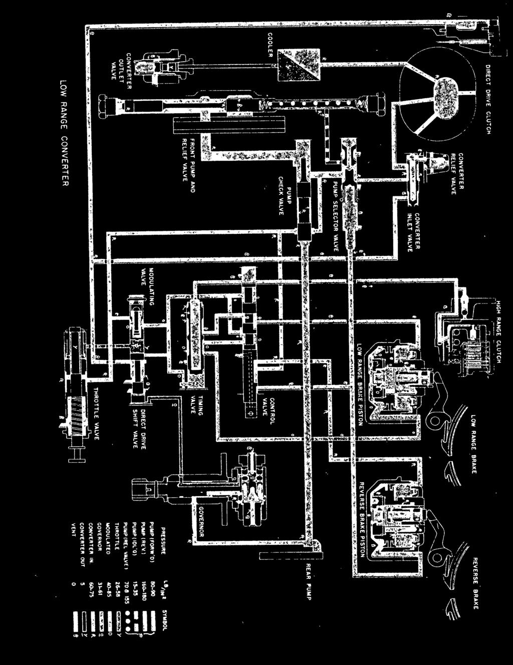
59 IlIIIB-SIH i» W ^ 10


60 " ///'


61 ffl IX P K> O


62 -_ t? V * 8 a *" j> a Is :.» a ji» _ p m o ar lotiuqisiij «<> l-i»,0 O -<


63 f* rsi *r tn 8 * S I fi «. f «j UJ X uj _l - O l- Q. 2SS>(CO> Z 5. a. a. a: a > > 3IOOOOUJ zz X o o o > i


64 The original charts were printed in color, and we have coded them for you in case you want to reproduce the colors. The key is as follows: R Red R Red R Red R Red Y Yel low Orange 0_ Pale Orange R Red Y Pale Yel low B B 1 ue

65
AUTOMATIC TRANSMISSIONS Mitsubishi F3A20 Series TRANSMISSION APPLICATION TABLE
 Article Text ARTICLE BEGINNING AUTOMATIC TRANSMISSIONS Mitsubishi F3A20 Series APPLICATION TRANSMISSION APPLICATION TABLE Vehicle Application Transmission Model Colt 3-Speed (1990-94)... F3A21 Colt Vista
AUTOMATIC TRANSMISSIONS. General Motors Corp. Hydra-Matic 4L60-E Overhaul
 1997-98 AUTOMATIC TRANSMISSIONS General Motors Corp. Hydra-Matic 4L60-E Overhaul APPLICATION TRANSMISSION APPLICATIONS Application Corvette Transaxle 4L60-E IDENTIFICATION The 4L60-E transmission can be
DRIVE AXLE Volvo 960 DESCRIPTION & OPERATION AXLE IDENTIFICATION DRIVE AXLES Volvo Differentials & Axle Shafts
 DRIVE AXLE 1994 Volvo 960 1994 DRIVE AXLES Volvo Differentials & Axle Shafts 960 DESCRIPTION & OPERATION All 960 station wagon models use type 1041 rear axle assembly. All 960 4-door models use type 1045
Torqueflite Manual/Automatic Valve Body
 TCI 122400 Torqueflite Manual/Automatic Valve Body This valve body can be installed in a few hours by carefully following directions. Read all instructions first to familiarize yourself with the parts
Torqueflite Trans-Scat Kit
 TCI 220000 Torqueflite Trans-Scat Kit This kit can be installed in a few hours by carefully following directions. Read all instructions first to familiarize yourself with the parts and procedures. Work
Installation Instructions
 Preparing your vehicle to install your brake system upgrade 1. Rack the vehicle. 2. If you don t have a rack, then you must take extra safety precautions. 3. Choose a firmly packed and level ground to
1 Green Pressure Regulator Spring Automatic transmissions operate at temperatures between 150ºF and
 Installation Instructions for 603107 Valve Body Kit C-4 1970 & Later Tools Required Speed Handle or Ratchet 3/8 Drive 1/2 Socket 3/8 Drive 7/16 Socket 3/8 Drive 5/16 Socket 3/8 Drive Small Screwdriver
Maintenance Information
 16572679 Edition 2 May 2014 Air Drill QP Series Maintenance Information Save These Instructions Product Safety Information WARNING Failure to observe the following warnings, and to avoid these potentially
2002 F-Super Duty /Excursion Workshop Manual
 Page 1 of 25 SECTION 307-01: Automatic Transaxle/Transmission 2002 F-Super Duty 250-550/Excursion Workshop Manual ASSEMBLY Procedure revision date: 05/23/2001 Transmission Special Tool(s) Remover, O-Ring
ASSEMBLY. Transmission Automatic Transaxle/Transmission. Special Tool(s) Alignment Set, Fluid Pump 307-S039 (T74P X) Special Tool(s)
 Alignment Set, Fluid Pump 307-S039 (T74P X) Special Tool(s)") 307-01-1 Automatic Transaxle/Transmission 307-01-1 ASSEMBLY Transmission Special Tool(s) Adjustment Set, Transmission Band 307-S022 (T71P-77370-A) Special Tool(s) Alignment Set, Fluid Pump 307-S039 (T74P-77103-X)
307-01-1 Automatic Transaxle/Transmission 307-01-1 ASSEMBLY Transmission Special Tool(s) Adjustment Set, Transmission Band 307-S022 (T71P-77370-A) Special Tool(s) Alignment Set, Fluid Pump 307-S039 (T74P-77103-X)
ASSEMBLY. Transmission Automatic Transmission 5R44E and 5R55E. Special Tool(s)
") 307-01-1 Automatic Transmission 5R44E and 5R55E 307-01-1 ASSEMBLY Transmission Special Tool(s) Holding Fixture, Transmission 307-262 (T93T-77002-AH) Special Tool(s) Installer, Transmission Extension Housing
307-01-1 Automatic Transmission 5R44E and 5R55E 307-01-1 ASSEMBLY Transmission Special Tool(s) Holding Fixture, Transmission 307-262 (T93T-77002-AH) Special Tool(s) Installer, Transmission Extension Housing
Return to Instruction Sheet index. Installation Instructions For C-4 70 and Later, Except 70 Falcon
 Page 1 of 8 Return to Instruction Sheet index TCI 260100 Trans-Scat Automatic Transmission Installation Instructions For C-4 70 and Later, Except 70 Falcon TCI 260100 Kit Contains: Qty. Description One
TCI TRANS-SCAT
 Page 1 of 9 Return to Instruction Sheet index TCI 360000 TRANS-SCAT Installation Instructions for FORD C-6 Transmissions TCI s TRANS-SCAT kit will allow you to calibrate the performance of your transmission.
Geo Prizm ( LSi) Toyota Celica 1.8L (1994)
 Toyota Celica 1.8L (1994)") Page 1 of 140 ARTICLE BEGINNING APPLICATION TRANSMISSION APPLICATIONS Application Geo Prizm (1993-94 LSi) Toyota Celica 1.6L (1993) Celica 1.8L (1994) Celica 2.2L (1993) Corolla 1.8L MR2 Paseo Transaxle
Page 1 of 140 ARTICLE BEGINNING APPLICATION TRANSMISSION APPLICATIONS Application Geo Prizm (1993-94 LSi) Toyota Celica 1.6L (1993) Celica 1.8L (1994) Celica 2.2L (1993) Corolla 1.8L MR2 Paseo Transaxle
2001 Chevrolet Corvette AUTOMATIC TRANSMISSIONS Hydra-Matic 4L60-E - Overhaul
 2001-03 AUTOMATIC TRANSMISSIONS Hydra-Matic 4L60-E - Overhaul APPLICATION CAUTION: Flush oil cooler and oil cooler lines prior to transmission installation. Oil cooling system contamination may cause premature
Hudson-Essex. Service Manual Supplement. Hudson Cars 750,001 up
 1 9 2 6 Hudson-Essex Service Manual 1927 Supplement Hudson Cars 750,001 up Hudson Rear Axle (Cars numbered 750,001 and upward) Brakes (Cars numbered 750,001 and upward) See page 18 Transmission Group
1 of 25 9/12/2013 9:07 PM
 1 of 25 9/12/2013 9:07 PM 46RE Automatic Transmission DISASSEMBLY 1. Clean exterior of transmission with suitable solvent or pressure washer. 2. Place transmission in vertical position. 3. Measure the
2005 Toyota RAV AUTOMATIC TRANSMISSIONS U240E & U241E Overhaul
 2001-05 AUTOMATIC TRANSMISSIONS U240E & U241E Overhaul APPLICATION CAUTION: Flush oil cooler and oil cooler lines prior to transaxle installation. Oil cooling system contamination may cause premature transaxle
MANUAL TRANS OVERHAUL - BORG-WARNER - T56 6-SPEED MANUAL TRANSMISSIONS Borg-Warner T56 (MM6) 6-Speed
 6-Speed") IDENTIFICATION MANUAL TRANS OVERHAUL - BORG-WARNER - T56 6-SPEED 1998 MANUAL TRANSMISSIONS Borg-Warner T56 (MM6) 6-Speed Transmission has 2 identification labels, located on lower left side of case. One
IDENTIFICATION MANUAL TRANS OVERHAUL - BORG-WARNER - T56 6-SPEED 1998 MANUAL TRANSMISSIONS Borg-Warner T56 (MM6) 6-Speed Transmission has 2 identification labels, located on lower left side of case. One
Transmission Overhaul Procedures-Bench Service
 How to Assemble the Lower Reverse Idler Gear Assembly Special Instructions In 1996 Eaton changed the reverse idler system design. In the nut design, the reverse idler bearing was lubricated through a hole
TCI Turbo 400 Full Manual Valve Body. Shift Pattern: Park Reverse Neutral First Second Third. NOTE: You must reuse stock manual control valve.
 TCI 221100 Turbo 400 Full Manual Valve Body Shift Pattern: Park Reverse Neutral First Second Third This Kit Contains: (1) Turbo 400 Full Manual Valve Body (1) Separator Plate & Gaskets (1) Pressure Regulator
Chrysler TorqueFlite Shift Improver Kit Part No A-727 (V-8) A-904 (V-8) (A-998 & A-999)
 A-904 (V-8) (A-998 & A-999)") FORM # 9500606-03 Installation Instructions Chrysler TorqueFlite Shift Improver Kit Part No. 10225 1971-1977 A-727 (V-8) 1971-1977 A-904 (V-8) (A-998 & A-999) 1998, 2005, 2010 by B&M Racing & Performance
FORM # 9500606-03 Installation Instructions Chrysler TorqueFlite Shift Improver Kit Part No. 10225 1971-1977 A-727 (V-8) 1971-1977 A-904 (V-8) (A-998 & A-999) 1998, 2005, 2010 by B&M Racing & Performance
CLUTCH CONTENTS SERVICE DIAGNOSIS. (a) Worn or damaged disc assembly. (b) Grease or oil on disc facings. (c) Improperly adjusted cover assembly.
 Worn or damaged disc assembly. (b) Grease or oil on disc facings. (c) Improperly adjusted cover assembly.") CLUTCH CONTENTS -GROUP 6 Page CLUTCH HOUSING ALIGNMENT... 6 CLUTCH PEDAL FREE PLAY 1 CLUTCH RELEASE BEARING 5 CLUTCH RELEASE FORK... 5 CLUTCH SERVICING 2 PILOT BUSHING CRANKSHAFT TO TRANSMISSION DRIVE
CLUTCH CONTENTS -GROUP 6 Page CLUTCH HOUSING ALIGNMENT... 6 CLUTCH PEDAL FREE PLAY 1 CLUTCH RELEASE BEARING 5 CLUTCH RELEASE FORK... 5 CLUTCH SERVICING 2 PILOT BUSHING CRANKSHAFT TO TRANSMISSION DRIVE
Return to Instruction Sheet index TCI Torqueflite Trans-Scat Kit
 Page 1 of 11 Return to Instruction Sheet index TCI 220000 Torqueflite Trans-Scat Kit This kit can be installed in a few hours by carefully following directions. Read all instructions first to familiarize
Maintenance Information
 16573347 Edition 2 February 2014 Air Grinder Series 88H Maintenance Information Save These Instructions Product Safety Information WARNING Failure to observe the following warnings, and to avoid these
SECTION 5B MANUAL TRANSMISSION TABLE OF CONTENTS
 SECTION 5B MANUAL TRANSMISSION TABLE OF CONTENTS General Description and Operation... 5B-2 Shift Lever... 5B-2 Transmission Assembly... 5B-2 Specifications... 5B-3 Diagnostic Information and Procedures...
Maintenance Information
 04581245 Edition 2 May 2014 Air Grinder, Die Grinder and Sander Series G2 (Angle) Maintenance Information Save These Instructions Product Safety Information WARNING Failure to observe the following warnings,
This file is available for free download at
 This file is available for free download at http://www.iluvmyrx7.com This file is fully text-searchable select Edit and Find and type in what you re looking for. This file is intended more for online viewing
Maintenance Information
 80234313 Edition 1 June 2006 Air Grinder, Die Grinder, Sander and Belt Sander Series G1 (Angle) Maintenance Information Save These Instructions WARNING Always wear eye protection when operating or performing
 Page 1 of 22 SECTION 307-01: Automatic Transaxle/Transmission 4R70E/4R75E ASSEMBLY Procedure revision date: 05/29/2009 Transmission Printable View (1554 KB) Special Tool(s) Air Test Plate, Transmission
Maintenance Information
 45528270 Edition 1 June 2007 Barring Motor T480 Series Maintenance Information Save These Instructions WARNING Always wear eye protection when operating or performing maintenance on this Barring Motor.
980 B Wheel Loader S/n 89P1 & Up Volume 1 of 2
 Caterpillar Service Manual 980 B Wheel Loader S/n 89P1 & Up Volume 1 of 2 Service Manual THIS IS A MANUAL PRODUCED BY JENSALES INC. WITHOUT THE AUTHORIZATION OF CATERPILLAR OR IT S SUCCESSORS. CATERPILLAR
Maintenance Instructions
 General Note These instructions contain information common to more than one model of Bevel Gear Drive. To simplify reading, similar models have been grouped as follows: GROUP 1 Models 11, 0, 1,, (illustrated),,
Return to Instruction Sheet index TCI Installation Instructions for Turbo Hydramatic 350C & 250C
 Page 1 of 6 Return to Instruction Sheet index TCI 326300 Installation Instructions for Turbo Hydramatic 350C & 250C NOTE: This kit was not intended for installation in transmissions that are in poor general
Maintenance Information
 80234313 Edition 2 May 2014 Air Grinder, Die Grinder, Sander and Belt Sander Series G1 (Angle) Maintenance Information Save These Instructions Product Safety Information WARNING Failure to observe the
TCI Trans-Scat
 Page 1 of 5 Return to Instruction Sheet index TCI 400000 Trans-Scat Turbo Hydramatic 400-1965-Up This kit will allow you to re-program your transmission valve body. This kit will give you firm positive
TRANSMISSION AND TRANSFER CASE
 DR TRANSMISSION AND TRANSFER CASE 21-1 TRANSMISSION AND TRANSFER CASE TABLE OF CONTENTS page MANUAL TRANSMISSION- G56- SERVICE INFORMATION...1 MANUAL TRANSMISSION- GETRAG 238- SERVICEINFORMATION...69 MANUAL
Maintenance Information
 16575219 Edition 4 October 2013 Air Screwdrivers QP1P, QP1S and QP1T Series Maintenance Information Save These Instructions Product Safety Information WARNING Failure to observe the following warnings,
1988 Chevrolet Pickup V SUSPENSION - FRONT (4WD)' 'Front Suspension - "V" Series 1988 SUSPENSION - FRONT (4WD) Front Suspension - "V" Series
' 'Front Suspension - V Series 1988 SUSPENSION - FRONT (4WD) Front Suspension - V Series") 1988 SUSPENSION - FRONT (4WD) Front Suspension - "V" Series DESCRIPTION NOTE: Vehicle serial numbers used in this article has been abbreviated for common reference to Chevrolet and GMC models. Chevrolet
1988 SUSPENSION - FRONT (4WD) Front Suspension - "V" Series DESCRIPTION NOTE: Vehicle serial numbers used in this article has been abbreviated for common reference to Chevrolet and GMC models. Chevrolet
Maintenance Information
 16584062 Edition 3 December 2013 High Torque Reversible Angle Screwdrivers and Angle Wrenches QA1L High Torque Series Maintenance Information Save These Instructions Product Safety Information WARNING
A/C COMPRESSOR SERVICING Article Text 1991 Saab 9000 For Copyright 1997 Mitchell International Friday, October 15, :22PM
 Article Text ARTICLE BEGINNING 1991 GENERAL SERVICING Compressor Service * PLEASE READ THIS FIRST * CAUTION: When discharging air conditioning system, use only approved refrigerant recovery/recycling equipment.
SD Bendix DD-3 & SD-3 Safety Actuators PUSH PLATE & SHAFT ASSY. LOCKPORT SERVICE DIAPHRAGM SEPARATOR LOCKING PISTON O-RING LOCKING PISTON
 SD-02-4600 Bendix DD-3 & SD-3 Safety Actuators AUXILIARY DIAPHRAGM SERVICE DIAPHRAGM SEPARATOR PUSH PLATE & SHAFT ASSY. LOCKING PISTON O-RING LOCKING PISTON LOCKPORT DRAIN SLOT RETURN SPRING CAP O-RING
Transaxle. 1. Mount the transaxle to Bench Mounted Holding Fixture T57L-500-B.
 «1997 Aspire Table of Contents» «Group 07: TRANSAXLE» «Section 07-01: Transaxle, Automatic» «DISASSEMBLY» Transaxle CAUTION: To prevent dirt from entering the transaxle, it should be disassembled and kept
Maintenance Information
 16573370 Edition 2 February 2014 Air Grinder 99V Series Maintenance Information Save These Instructions Product Safety Information WARNING Failure to observe the following warnings, and to avoid these
13. CRANKCASE/CRANKSHAFT/BALANCER/PISTON/CYLINDER
 13. CRANKCASE/CRANKSHAFT/BALANCER/PISTON/CYLINDER COMPONENT LOCATION 13-2 SERVICE INFORMATION 13-3 TROUBLESHOOTING 13-4 CRANKCASE SEPARATION 13-5 CRANKSHAFT 13-7 MAIN JOURNAL BEARING 13-9 CRANKPIN BEARING
Installation Instructions Z-Gate Shifter
 Installation Instructions Z-Gate Shifter Part Number 80681 1998, 2001 by B&M Racing and Performance Products The B&M Z-Gate shifter can be used in vehicles equipped with most popular three speed automatic
MODELS 3100,3130,3160, 1300, 1330,1360 EXHAUST SYSTEM
 MODELS 3100,3130,3160, 1300, 1330,1360 EXHAUST SYSTEM WALBRO CARBURETOR "WA" SERIES MUFFLER REMOVAL CARBURETOR REMOVAL The muffler assembly should beremoved periodically to inspect for excessive carbon
INTEGRAL POWER STEERING GEAR FORD Applies to F-100 F-350 (4X2), F-150 F-250 (4X4) And Bronco
, F-150 F-250 (4X4) And Bronco") Rockcrawler Steering Shop Manual page1 The following is from the Ford 1978 Truck Shop Manual, Volume 1 Chassis. It is provided here as a courtesy to classic Ford owners who would like to perform their
Rockcrawler Steering Shop Manual page1 The following is from the Ford 1978 Truck Shop Manual, Volume 1 Chassis. It is provided here as a courtesy to classic Ford owners who would like to perform their
SPECIAL TOOLS Dodge Pickup 5.9L Eng R3500. Fig 1: Identifying Remover C-3985-B (Special Tool) 9/6/13 Printer Friendly View
 9/6/13 Printer Friendly View") Procedures 2003 Dodge Pickup 5.9L Eng R3500 manual transmission SPECIAL TOOLS Fig 1: Identifying Remover C-3985-B (Special Tool) www2.prodemand.com/print/index?content=tabs&module=true&tab=true&terms=true&ymms=false&classname=
Procedures 2003 Dodge Pickup 5.9L Eng R3500 manual transmission SPECIAL TOOLS Fig 1: Identifying Remover C-3985-B (Special Tool) www2.prodemand.com/print/index?content=tabs&module=true&tab=true&terms=true&ymms=false&classname=
Installation Instructions for TCI Turbo 700R TCI Turbo 700R
 Installation Instructions for TCI 378805 Turbo 700R4 1982-1984 TCI 378905 Turbo 700R4 1985-1993 KIT INTRODUCTION Read all instructions first to familiarize yourself with the parts and procedures. Work
Maintenance Information
 Form 16573321 Edition 1 July 2004 Air Grinder Series 61H Maintenance Information Save These Instructions Always wear eye protection when operating or performing maintenance on this tool. Always turn off
CLUTCH. Section IV DATA AND SPECIFICATIONS CHRYSLER SERVICE MANUAL. Page. Clutch Pedal Adjustment 74. Clutch Disassembly 77. Clutch Assembly 78
 CLUTCH 73 Section IV CLUTCH Page Clutch Pedal Adjustment 74 Clutch Disassembly 77 Clutch Assembly 78 Service Diagnosis 81 DATA AND SPECIFICATIONS MODEL TYPE 1376 (Borg-Beck) Single Plate, Dry Disc FACINGS
CALIFORNIA TRIMMER MOWER MAINTENANCE MANUAL
 CALIFORNIA TRIMMER MOWER MAINTENANCE MANUAL 2 Table of Contents Section 1: General Information Page Handle Assembly Instructions 4 Maintenance All Models 6 Oil Change Procedures All Models 9 Height Adjustment
Service Manual. #19 Gearmatic Winch
 Allis Chalmers Service Manual #19 Gearmatic Winch Service Manual THIS IS A MANUAL PRODUCED BY JENSALES INC. WITHOUT THE AUTHORIZATION OF ALLIS CHALMERS OR IT S SUCCESSORS. ALLIS CHALMERS AND IT S SUCCESSORS
Part No amatic 350
 Watch our installation video on YouTube Installation Instructions Shift Improver Kit Part No. 30262 1968-1981 TurboHy urbohydr drama amatic 350 B&M Racing and Performance Products 2002 Congratulations!
SPECIFICATIONS TEST AND ADJUSTMENT SPECIFICATIONS SPECIFICATIONS ENGINE FD620D, K SERIES
 ENGINE FD620D, K SERIES SPECIFICATIONS SPECIFICATIONS TEST AND ADJUSTMENT SPECIFICATIONS Engine Oil Pressure Sensor Activates............................... 98 kpa (14.2 psi) Oil Pressure While Cranking
Jatco 5 Speed ATRA. All Rights Reserved. Printed in U.S.A.
 1 2 3 Table Of Contents Transmission Diassembly... 4 Front Pump... 16 Reverse/High Clutch Drum... 18 Direct Clutch Drum... 22 Low Clutch Drum... 26 Planetary Gearsets... 29 Transfer Gear/Reduction Gear...
Maintenance Information
 16575243 Edition 2 October 2013 Air Screwdrivers 1R Series Maintenance Information Save These Instructions Product Safety Information WARNING Failure to observe the following warnings, and to avoid these
Installation Instructions Pro Stick Shifter
 Installation Instructions Pro Stick Shifter Part Number 80701, 80702 & 80706 2012, 2010, 2008, 2001, 1998 by B&M Racing and Performance Products The B&M Pro Stick shifter #80701 and #80706 comes equipped
FOREWORD ALPHABETICAL INDEX
 FOREWORD I This manual is a guide and a reference book to be used in the proper servicing of the Hudson Automatic Transmission. The procedures covering: Operation, testing, diagnosis, adjustments, removal,
Brake System H TX, H2.0TXS [B475]; H TX [B466] Safety Precautions Maintenance and Repair
![Brake System H TX, H2.0TXS [B475]; H TX [B466] Safety Precautions Maintenance and Repair](/thumbs/86/93834005.jpg "Brake System H TX, H2.0TXS [B475]; H TX [B466] Safety Precautions Maintenance and Repair") HMM180001 Brake System H1.5-1.8TX, H2.0TXS [B475]; H2.5-3.5TX [B466] Safety Precautions Maintenance and Repair When lifting parts or assemblies, make sure all slings, chains, or cables are correctly fastened,
HMM180001 Brake System H1.5-1.8TX, H2.0TXS [B475]; H2.5-3.5TX [B466] Safety Precautions Maintenance and Repair When lifting parts or assemblies, make sure all slings, chains, or cables are correctly fastened,
Installation Instructions Shifter Improver Kit Fits:1988 and Later TurboHydramatic 400, TH-400/TH-475 (3L80/3L80-HD) Catalog # 20261
 Catalog # 20261") Installation Instructions Shifter Improver Kit Fits:1988 and Later TurboHydramatic 400, TH-400/TH-475 (3L80/3L80-HD) Catalog # 20261 WORK SAFELY! For maximum safety, perform this installation on a clean,
Installation Instructions Shifter Improver Kit Fits:1988 and Later TurboHydramatic 400, TH-400/TH-475 (3L80/3L80-HD) Catalog # 20261 WORK SAFELY! For maximum safety, perform this installation on a clean,
SECTION 4 - FUEL/LUBRICATION/COOLING
 For Arctic Cat Discount Parts Call 606-678-9623 or 606-561-4983 SECTION 4 - FUEL/LUBRICATION/COOLING 4 TABLE OF CONTENTS Carburetor Specifications... 4-2 Carburetor Schematic... 4-2 Carburetor... 4-3 Cleaning
DISASSEMBLY. Transmission. All vehicles
 307-01-1 Automatic Transmission 5R44E and 5R55E 307-01-1 DISASSEMBLY Transmission Special Tool(s) Holding Fixture, Transmission 307-262 (T93T-77002-AH) Special Tool(s) Remover, Servo 307-347 (T97T-7D021-A)
Maintenance Information
 16573321 Edition 3 February 2014 Air Grinder Series 61H Maintenance Information Save These Instructions Product Safety Information WARNING Failure to observe the following warnings, and to avoid these
TCI Trans-Scat
 Page 1 of 5 Return to Instruction Sheet index TCI 350000 Trans-Scat Installation Instructions For TURBO HYDRAMATIC 350 This kit will allow you to reprogram your transmission to meet your driving needs
BRAKE SYSTEM Toyota Celica DESCRIPTION DRUM BRAKES ADJUSTMENTS BRAKE PEDAL HEIGHT ADJUSTMENTS BRAKE PEDAL FREE PLAY ADJUSTMENTS
 BRAKE SYSTEM 1988 Toyota Celica 1988-89 BRAKES Toyota Celica, Corolla, MR2, Tercel DESCRIPTION The hydraulic brake system uses a tandem master cylinder with a vacuum power assist servo. MR2 and some Celica
Installation Instructions. QuickSilver Shifter. Fits: GM, Ford, Chrysler Transmissions See Application Guide for Specific Applications Part # 80683
 Installation Instructions QuickSilver Shifter Fits: GM, Ford, Chrysler Transmissions See Application Guide for Specific Applications Part # 80683 WORK SAFELY! For maximum safety, perform this installation
Installation Instructions Transpak Fits: GM Turbo-Hydramatic 400, Turbo-Hydramatic 375 and M40 Automatic Transmission Catalog # 20228
 Installation Instructions Transpak Fits: 1965-1987 GM Turbo-Hydramatic 400, Turbo-Hydramatic 375 and M40 Automatic Transmission Catalog # 20228 WORK SAFELY! For maximum safety, perform this installation
This file is available for free download at
 This file is available for free download at http://www.iluvmyrx7.com This file is fully text-searchable select Edit and Find and type in what you re looking for. This file is intended more for online viewing
Maintenance Information
 Form 04584058 Edition 1 November 2004 Air Impactool 2141P and 2141PSP Maintenance Information Save These Instructions Disassembly General Instructions 1. Do not disassemble the tool any further than necessary
2003 E-Series Workshop Manual
 Page 1 of 20 SECTION 307-01B: Automatic Transmission 4R70W 2003 E-Series Workshop Manual ASSEMBLY Procedure revision date: 04/27/2006 Transmission Printable View (1828 KB) Special Tool(s) Dial Indicator
22-1 GROUP 22 MANUAL TRANSAXLE CONTENTS MANUAL TRANSAXLE... 22A MANUAL TRANSAXLE OVERHAUL... 22B
 22-1 GROUP 22 MANUAL TRANSAXLE CONTENTS............................... 22A OVERHAUL..................... 22B 22A-2 GROUP 22A MANUAL TRANSAXLE CONTENTS GENERAL DESCRIPTION......... 22A-3 DIAGNOSIS 22A-6
CLUTCH Nissan 240SX DESCRIPTION PEDAL HEIGHT & FREE PLAY ADJUST CLUTCH ASSEMBLY R & I Clutch. Pathfinder, Pickup, 240SX, 300ZX
 CLUTCH 1990 Nissan 240SX 1990 Clutch Pathfinder, Pickup, 240SX, 300ZX DESCRIPTION Clutch is of dry, single disc type, with a diaphragm spring type pressure plate. Clutch release bearing is prelubricated.
 DRUM BRAKE RIMS Periodic inspection of drum brake rims is necessary to determine indications of uneven or excessive wear. In general, brake rim failures other that regular wear are caused by brake linings
4.2 WATER PUMP (GEAR CASE MOUNTED AND LATER) (GCM)
 (GCM)") SERIES 60 SERVICE MANUAL 4.2 WATER PUMP (GEAR CASE MOUNTED - 1991 AND LATER) (GCM) The centrifugal-type water pump circulates the engine coolant through the cooling system. The pump is mounted on the rear
SERIES 60 SERVICE MANUAL 4.2 WATER PUMP (GEAR CASE MOUNTED - 1991 AND LATER) (GCM) The centrifugal-type water pump circulates the engine coolant through the cooling system. The pump is mounted on the rear
SPECIFICATIONS TEST AND ADJUSTMENT SPECIFICATIONS SPECIFICATIONS ENGINE FD620D, K SERIES
 TEST AND ADJUSTMENT Engine Oil Pressure Sensor Activates............................... 98 kpa (14.2 psi) Oil Pressure While Cranking (Minimum).......................... 28 kpa (4 psi) Oil Pressure.....................................
DESCRIPTION FUEL AND VACUUM PUMP REMOVE AND REPLACE FUEL PUMP-OVERHAUL 6B PONTIAC SHOP MANUAL. S. Install battery and connect cables.
 6B-74 1955 PONTIAC SHOP MANUAL DESCRIPTION FUEL AND VACUUM PUMP All models are equipped with a combination fueland double acting vacuum pump operated by an eccentric bolted to the front end of the engine
Spring Brake Application
 Technical Tip Maxibrake I Series Spring Brakes Disassembly, Inspections and Reconditioning Instructions Maxibrake I Series spring brake products are mechanical devices and are subject to wear after extended
CRANKSHAFT & MAIN BEARINGS
 CRANKSHAFT & MAIN BEARINGS * PLEASE READ THIS FIRST * REMOVAL Ensure all main bearing caps are marked for location on cylinder block. Some main bearing caps have an arrow stamped on them. The arrow must
BRAKES. Section III REAR AXLE DATA AND SPECIFICATIONS HAND BRAKE CHRYSLER SERVICE MANUAL BRAKES 17
 BRAKES 17 There is no basic design change in the rear axle and sure grip differential except the larger diameter pinion shaft is now used on all models for 1959. The Service Procedures will remain the
AUTOMATIC TRANSMISSIONS ZF 4HP 18
 AUTO TRANS OVERHAUL - ZF 4HP 18 Article Text 1991 Eagle Premier For Dan's Transmission Service 10 Jefferson Place Fort Walton Beach FL 32548 1997 Mitchell Repair Information Company, All Rights Reserved.
BRAKE SYSTEM Nissan 240SX DESCRIPTION BRAKE BLEEDING * PLEASE READ FIRST * BLEEDING PROCEDURES ADJUSTMENTS BRAKE PEDAL HEIGHT SPECS TABLE
 BRAKE SYSTEM 1990 Nissan 240SX 1990 BRAKE SYSTEMS Nissan Disc & Drum Axxess, Maxima, Pathfinder, Pickup, Pulsar NX, Sentra, Stanza, 240SX, 300ZX DESCRIPTION All brake systems are hydraulically operated
TRANSMISSION 6.7 GENERAL HOME. See Figure The transmission is a five-speed constantmesh type housed in an extension of the crankcase.
 TRANSMISSION 6.7 GENERAL See Figure 6-45. The transmission is a five-speed constantmesh type housed in an extension of the crankcase. Mainshaft Neutral Mainshaft st Gear b06x6x Countershaft 4 Out 5 Countershaft
Module 6: Air Foundation Brakes
 Air Brakes Terms and Definitions Basic Components That Make Up Air Foundation Brakes Types of Air Foundation Brakes Parts of a Cam Foundation Brake Parts of a Wedge Foundation Brake Parts of a Disc Foundation
Z-Gate Universal Shifter
 Installation Instructions Z-Gate Universal Shifter Fits: GM, Ford, Lincoln and Chrysler Transmissions See Application Guide for Specific Applications Part #80681 Rev 06/01/2018 WORK SAFELY! For maximum
 a. SCOPE. g. : RA PD 28742 TM 9;1803B 2. MWO AND MAJOR UNIT ASSEMBLY REPLACEMENT RECORD. a. Description. b. _Instructions for Use. Early Modifications. CHAPTER 2 Section I 3. POWER TRAIN DESCRIPTION. a.
UNIVERSAL JOINTS AND PROPELLER SHAFT
 Section XII UNIVERSAL JOINTS AND SERVICE BULLETIN REFERENCE NUMBER DATE SUBJECT CHANGES UNIV JOINTS AND 537 UNIVERSAL JOINTS AND DATA AND SPECIFICATIONS Propeller Shaft Number used C-67 C-68 C-69 C-70
TRANSMISSION PARTS Instructions
 TRANSMISSION PARTS Instructions Sure Cure Kit Part No. SC-4T65E GM 4T65-E Valve Body Parts Boost Valve Kit 84754-30K Patent No. 6,832,632 TCC Apply Valve Kit 84754-43K Patent No. 7,100,753 TCC Regulated
12 September 2012 Valve Body # , , ,
 12 September 2012 Valve Body # 1030416, 1030417, 1030418, 1030419 1 BD VALVE BODY For 1996-2004 Dodge 5.9L 12V/24V Cummins Trucks -- I n s t a l l a t i o n I n s t r u c t i o n s -- 1030416 1996-1998
2003 Dodge Pickup R DRIVE AXLES' 'Axle Shafts - Front - Ram Pickup WD DRIVE AXLES
 2002-04 DRIVE AXLES Axle Shafts - Front - Ram Pickup 1500 4WD DESCRIPTION Vehicles equipped with 4WD and C205F front axle assembly use equal length axle shaft system to deliver power from front differential
RESERVOIR POWER CYLINDER SCHEMATIC DRAWING OF HYDRAULIC FLOW IN NEUTRAL OR STRAIGHT AHEAD POSITION POWER STEERING GEAR AND PUMP ~-BALL NUT
 9-10 1955 PONTIAC SHOP MANUAL POWER STEERING GEAR AND PUMP GENERAL DESCRIPTION Power steering is a combination of a recirculating ball nut steering gear and a hydraulic booster linked to the pitman shaft
HKS 700E. Service Manual June Ver. 2.04
 HKS 700E Service Manual 009 June Ver..04 HKS CO.,LTD 78 KITAYAMA FUJINOMIYA SHIZUOKA JAPAN 48-09 TEL +8(0)544-54-78 FAX +8(0)544-54-40 hks_aviation@hks-power.co.jp http://www.hks-power.co.jp/hks_aviation/
Transmission Overhaul Procedures-Bench Service
 How to Install the Auxiliary Countershaft Assembly Special Instructions To make auxiliary section assembly easier, you can make an auxiliary section fixture out of a 2" x 12" piece of wood. 3' 1' 3" 4.56"
TRANS-SCAT Installation Instructions for Ford AOD
 TCI 436000 TRANS-SCAT Installation Instructions for Ford AOD 1980-1993 TCI 436000 Kit Contains: Qty. Description Five (5) Gaskets: Three (3) Valve Body One (1) Filter One (1) Duraprene Pan Two (2) Springs:
AUTOMATIC CLUTCH Models
 AUTOMATIC CLUTCH 1940 Models Source of this material is from 1940 Series, Issue 4, January 1940 Hudson Service Magazine AUTOMATIC CLUTCH 1940 MODELS The automatic clutch installation and adjustment procedure
The steering column is of a modular construction and features easy to service electrical switches.
 file://c:\tso\tsocache\vdtom_5368\svk~us~en~file=svkb4a01.htm~gen~ref.htm Page 1 of 3 Section 11-04A: Steering Column, Ranger DESCRIPTION AND OPERATION 1997 Ranger Workshop Manual Steering Column NOTE:
HYDRAULICS. TX420 & & lower. Hydraulic Tandem Pump Removal. 4. Remove the LH side panel (Fig. 0388).
.") TX420 & 425 240000299 & lower 4. Remove the LH side panel (Fig. 0388). Hydraulic Tandem Pump Removal Note: Cleanliness is a key factor in a successful repair of any hydraulic system. Thoroughly clean all
TX420 & 425 240000299 & lower 4. Remove the LH side panel (Fig. 0388). Hydraulic Tandem Pump Removal Note: Cleanliness is a key factor in a successful repair of any hydraulic system. Thoroughly clean all
Attention! The following must be done to maintain consistent staging with all Tranz Brake Valve Bodies for Three (3) Speed Automatics: Before
 Speed Automatics: Before") Attention! The following must be done to maintain consistent staging with all Tranz Brake Valve Bodies for Three (3) Speed Automatics: Before turning bottom final stage yellow light on, you should be at
Attention! The following must be done to maintain consistent staging with all Tranz Brake Valve Bodies for Three (3) Speed Automatics: Before turning bottom final stage yellow light on, you should be at
Chrysler 46RE, 46RH, 47RE, 47RH SURE CURE KIT
 Chrysler 46RE, 46RH, 47RE, 47RH SURE CURE KIT PART NUMBER SC-46-47RHE-OS INSTALLATION GUIDE Parts are labeled here in order of installation. See other side of sheet for details on Sure Cure kit contents.