V&P SCIENTIFIC LEVITATION STIR BALL LOADER. VP 725C-96 Operating Instructions
|
|
|
- Oscar Clark
- 5 years ago
- Views:
Transcription
 455-0643 Fax: (858) 455-0703 email: sales@vp-scientific.")
1 V&P SCIENTIFIC LEVITATION STIR BALL LOADER VP 725C-96 Operating Instructions TECHNICAL NOTE Pacific Heights Boulevard, Suite T, San Diego, CA (858) Fax: (858)
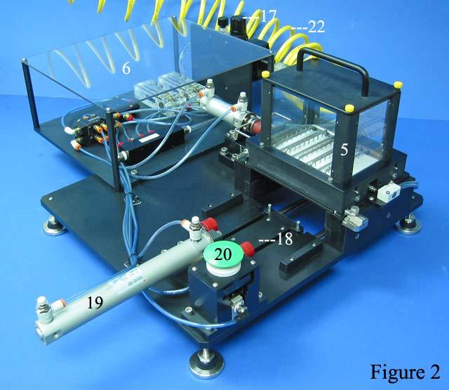
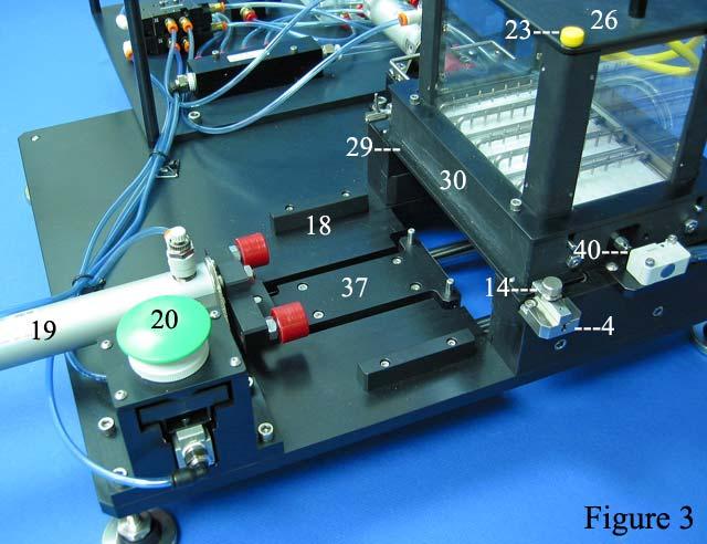
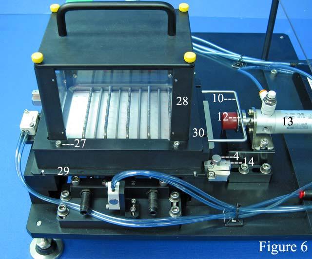
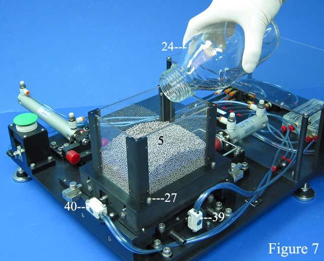
2 PREPARATION Warning: Do not make adjustments or place fingers in the machine while it is operating. Remove and sterilize Ball Hopper and Loading Plenums by completing the following steps: 1. Close the Air Valve (1) by turning counter-clockwise (Fig. 1). Bleed air pressure by pushing up on the Pressure Relief Valve (2) (Fig. 1). 2. Unscrew the two Locking Knobs (4) to release the Spring-loaded Bars (14) from the Ball Hopper Base (29) (Figs. 3 & 4). 3. Lift vertically to remove the Ball Hopper (5) and Ball Hopper Base (29) (Figs. 2, 3 & 4). 4. Place in autoclave wrap and autoclave on dry cycle. NOTE: It is very important that the plenums be dry before the balls are added Assemble sterilized Ball Hopper and Loading Plenums onto Ball Loader: 1. Remove autoclave wrap and aseptically place the Ball Hopper (5) (Fig. 2) and Ball Hopper Base (29) (Fig. 4) onto the Loader Platform (9) (Fig. 5). 2. Align the four notches (7) on the Ball Hopper Base to the four dowel pins (8) on the Loader Platform (9) (Figs 9 & 5). NOTE: It is very important that the Yoke (10) of the Ball Rake (11) be aligned to fit in the groove (12) on the Plenum Pneumatic Cylinder (13) (Fig 6). The best way to assure that Yoke (10) is in the right position is to adjust the Yoke position so the end of the Ball Rake (11) is even with the opposite end of the Loader Platform (9) (Figs. 5 & 6). 3. When the Ball Hopper Base (29) is in position, push in Spring-loaded Bars (14) and tighten the Locking Knobs (4) to lock in position (Fig. 6). 4. Connect Ball Loader to air line at Air Line Connector (15) and open Air Valve (1) (Fig. 1). Adjust pressure on the Air Pressure Gauge (41) to 80 to 90 PSI by raising the Cap (16) on Adjustment Knob (17) and then turning the knob (Fig. 1). NOTE: It is very important to operate at this pressure range. 5. Before loading Levitation Stir Balls, place an empty deep well 96 microplate in the Microplate Nest (18) in front of Microplate Pneumatic Cylinder (19) (Figs. 3 & 5). Perform a test by pushing Green Start Button (20) to ensure the pneumatic cylinders are working, the microplate is correctly aligned to the Ball Hopper (5) and the Limit Switches (39, 40) are functioning (Figs. 3 & 5). Repeat the cycle 3-4 times. NOTE: Do not push green button without placing microplate in the nest. If you do, the Microplate Pneumatic Cylinder will stall in the open position. If the microplate is not placed flat in the Microplate Nest (18) it will jam against the Ball Hopper Base (29) when the Green Start Button (20) is pushed (Fig. 3). To reset the Microplate Pneumatic Cylinder (19), manually trigger the two Limit Switch Air Valves (39 & 40) at the rear of the Levitation Ball Loader (Figs. 5 & 7). In order to access the switches remove the Ball Hopper Base (29) from the Loader Platform (9) (Fig. 5) as described above. 6. Make sure that the Mid Plate Plenum (21) (Fig. 8) and the Ball Rake (11) (Fig. 4) are being moved by the Plenum Pneumatic Cylinder (13). V&P Scientific, Inc. 2 Technical Note 178
3 OPERATION 1. Remove the four Thumb Screws (23) holding the Ball Hopper Lid (26) (Fig. 3) and fill the Ball Hopper (5) with clean, sterile, demagnetized Levitation Balls. Pour the Levitation Balls slowly at first because they bounce very high (Fig. 7). 2. Place a sterile deep well 96 microplate in the Microplate Nest (18) and push the Green Start Button (20) (Fig. 3). 3. Repeat the cycle three times in the same plate to allow the Ball Rake (11) to completely fill the Teflon Loading Plenum (25) (Fig. 8). 4. Remove the first microplate and dump the Levitation Stir Balls back into the Hopper. Re-attach the Ball Hopper Lid (26) (Fig. 7). 5. Replace the first microplate into the Microplate Nest (18) and press the Green Start Button (20) (Figs. 3 & 5). Examine the plate to confirm that every well was loaded with a Stir Ball. 6. Repeat cycle until the level of Levitation Stir Balls in the Ball Hopper goes down to within 1/2 inch of the Teflon Loading Plenum (25) (Fig 3). NOTE: Do not allow the hopper to run below this level. 7. Refill the Ball Hopper with sterile balls (Fig. 7) and keep repeating the cycle. 8. As long as aseptic conditions are maintained in the Ball Hopper, it can be re-filled with sterile Levitation Stir Balls and more plates can be loaded. DISASSEMBLY & MAINTENANCE Disassemble Ball Hopper and Loading Plenums: Caution: Perform this only if absolutely necessary, such as if Loading Plenums are in obvious need of cleaning or if Loader is not functioning properly and might be jammed with a ball or other object. 1. Remove the Thumb Screws (23) on the Ball Hopper Lid to remove the lid (Fig. 3). 2. Unscrew the two Locking Knobs (4) to release the Spring-loaded Bars (14) and the Ball Hopper and Loading Plenums (21 & 25) (Figs. 5 & 6). 3. Lift vertically to remove the Ball Hopper (5) and Ball Hopper Base (29) which will include the Loading Plenums (21 & 25) (Fig. 4). 4. Pour the remaining Levitation Stir Balls into a vessel. 5. Remove the four screws (27) holding the Ball Hopper Walls (28) to the Ball Hopper Base (29). Vertically lift the Flange Frame (30) and the Ball Hopper Walls (Fig. 6) from the Base. (Fig. 8) 6. Lift off the Ball Rake (11) (Fig. 9). 7. Pull the spring-loaded Plenum Retaining Pin (31) and twist it to hold in the open position (Fig. 10). 8. Pull out the Mid Plate Loading Plenum (21) (Fig. 10). V&P Scientific, Inc. 3 Technical Note 178
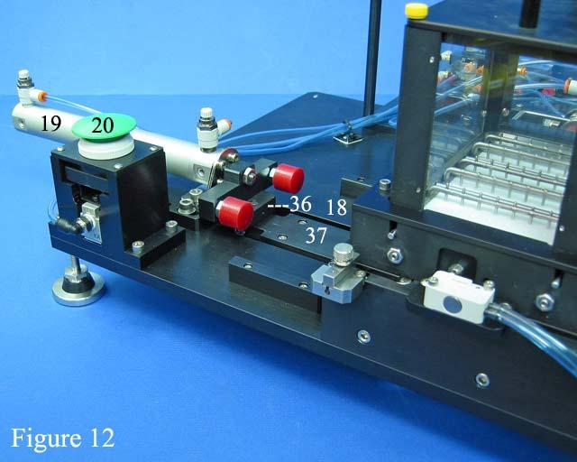
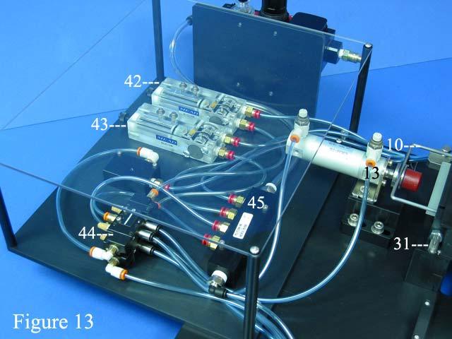
4 9. Lift the Teflon Loading Plenum (25) and the Lower Plate Plenum (33) out of the Ball Hopper Base (29) (Fig. 11). Caution: The plenums and base have very close tolerances. For ease, place a microplate under and apply equal pressure to push the plenum out. During disassembly and assembly make certain that the plenums do not become twisted relative to the Ball Hopper Base. If this does occur, gentle tapping with a wooden object is helpful to readjust. 10. Gently pry the Teflon Plenum (25) from the dowel pins holding it to the Lower Plate Plenum (33). Clean Loading Plenums and Ball Rake: 1. Visually inspect all the Loading Plenums and the Ball Rake for damage or wear. 2. Sonicate the Loading Plenums and the Ball Rake in a mild detergent (such as Micro 90 ), and use a cut off Q Tip shaft (not the tip) to clean all the holes. Rinse with tap water, then distilled water and then ethanol. 3. Examine under dissecting microscope to make sure there is no debris blocking the holes. Maintenance checks: 1. Check Break Away Connection (36) from Plate Car (37) to ensure that it will release if the microplate gets stuck under the Loader Base (Fig. 12). 2. Check the integrity of the incoming air line (22) (Fig. 2). 3. Check the Limit Switch Air Valve (39) which is activated by the Microplate Pneumatic Cylinder (19) (Figs. 4, 5 & 7). 4. Check the Limit Switch Air Valve (40) which is activated by the Plenum Pneumatic Cylinder (13) (Figs. 3, 5 & 7). 5. Check to insure the Air Pressure Gauge (41) is functioning by raising Cap (16) and turning Adjustment Knob (17) (Fig. 1). 6. Check that the Time-Delay Air Valve for Plenum Pneumatic Cylinder (42) has a 6 second delay, (Fig. 13). 7. Check that the Time-Delay Air Valve for Microplate Pneumatic Cylinder (43) has a 1-second delay (Fig. 13). 8. Check the integrity of the air lines entering and leaving the Directional Air Valve (44) and the Air Line Manifold (45) (Fig. 13). REASSEMBLY 1. Reassemble the Ball Hopper and Loading Plenums by reversing disassembly steps 1 through 10 in previous section. 2. When mating the Teflon Loading Plenum (25) to the Lower Plate Plenum (33) (Fig. 11), ensure that the Ball Rake Groves in the Teflon Loading Plenum are facing up. Also make sure that the lip end (bottom side of Teflon Loading Plenum) is at the same end of the Lower Plate Plenum containing the four notches (Fig. 11). 3. Place the 2 Plenums inside the Ball Hopper Base (29) (Fig. 11). Caution: The plenums and base have very close tolerances. During disassembly and assembly certain that the plenums do V&P Scientific, Inc. 4 Technical Note 178
 (Fig. 10).")
5 not become twisted relative to the Ball Hopper Base. If this does occur, gentle tapping with a wooden object is helpful to readjust. 4. The moveable Mid Plate Plenum is then inserted on the side with the Plenum Retaining Pin (31) (Fig. 10). When inserting the moveable Mid Plate Plenum (21) between the Teflon Loading Plenum (25) and the Lower Plate Plenum be sure that the lettering TOP remains on the upper (Teflon) side. 5. Turn the Plenum Retaining Pin (31) until it clicks and locks the moveable Mid Plate Plenum (21) inside (Fig. 10). 6. Place the Ball Rake (11) in the grooves on the Teflon Loading Plenum (25) (Fig. 9). 7. Align the four notches (7) on the Ball Hopper Base to the four dowel pins (8) on the Loader Platform (9) (Figs 9 & 5). NOTE: It is very important that the Yoke (10) of the Ball Rake (11) be aligned to fit in the groove (12) on the Plenum Pneumatic Cylinder (13) (Fig 6). If the Yoke is adjusted so the end of the Ball Rake is even with the opposite end of the Ball Hopper Base, the Yoke will fit into the groove (Fig. 6). 8. Place the Ball Hopper Walls (28) on to the Ball Hopper Base (29) (Fig 4). 9. Place the Flange Frame (30) over the Ball Hopper Walls (28) and fasten with the four screws (27) (Fig. 3). 10. Press in the Spring-loaded Bars (14) and tighten the two Locking Knobs (4) to attach the Ball Hopper and Loading Plenums to the Loader Platform (Fig 3 & 4). 11. The Levitation Ball Loader is now ready to operate, connect to compressed air line and adjust pressure to 80 to 90 PSI. Continue following instructions in Operations section. FIGURES: 3-- V&P Scientific, Inc. 5 Technical Note 178

6 29 V&P Scientific, Inc. 6 Technical Note 178

7 V&P Scientific, Inc. 7 Technical Note 178


8 V&P Scientific, Inc. 8 Technical Note 178

9 V&P Scientific, Inc. 9 Technical Note
10 PARTS LEGEND [Found in Figure #] (1) Air Valve [1] (2) Pressure Relief Valve [1] (3) On/Off Switch [1] (4) Locking Knob [3,5,6] (5) Ball Hopper [2,7] (6) Cover [2] (7) Ball Hopper Alignment Notches [4,9] (8) Dowel Pins on Loader Platform (9) Loader Platform [5] (10) Ball Rake Yoke [6, 8, 13] (11) Ball Rake [4, 8, 9] (12) Groove on the Plenum Pneumatic Cylinder [5, 6] (13) Plenum Pneumatic Cylinder [4, 5, 6, 13] (14) Spring-Loaded Bars [3,5,6] (15) Air Line Connector [1] (16) Air Pressure Adjustment Knob Cap [1] (17) Air Pressure Adjustment Knob [1] (18) Microplate Nest [2, 3, 12] (19) Microplate Pneumatic Cylinder [2, 3, 12] (20) Green Start Button [2, 3, 12] (21) Mid Plate Loading Plenum [8,9] (22) Airline [2] (23) Ball Hopper Lid Thumb Screws [3] (24) Bottle of Sterile Stir Balls [7] (25) Teflon Loading Plenum [8, 9, 10, 11] (26) Ball Hopper Lid [4, 6, 8] (27) Ball Hopper Flange Frame Screws [6, 7] (28) Ball Hopper Walls [4, 6, 8] (29) Ball Hopper Base [3, 4, 6, 8, 9, 10, 11] (30) Ball Hopper Flange Frame [3, 6, 8] (31) Spring Loaded Plenum Retaining Pin [10, 13] (32) (33) Lower Plate Loading Plenum [8, 11] (34) Plate Car Guide Rails [5] (35) (36) Break Away Connection [12] (37) Plate Car [3] (38) Microplate Bumper Stops [5] (39) Limit Switch Air Valve, Activated by Microplate Pneumatic Cylinder [4, 5, 7] (40) Limit Switch Air Valve, Activated by Plenum Pneumatic Cylinder [3, 7] (41) Air Pressure Gauge [1] (42) Time-Delay Air Valve for Plenum Pneumatic Cylinder[13] (43) Time-Delay Air Valve for Microplate Pneumatic Cylinder [13] (44) Directional Air Valve [13] (45) Air Line Manifold [13] V&P Scientific, Inc. 10 Technical Note 178
OPERATION MANUAL MiniStirrus MAGNETIC STIRRER VP 706B-3. Speed Control Knob Power Switch
 OPERATION MANUAL MiniStirrus MAGNETIC STIRRER VP 706B-3 TECHNICAL NOTE 212 Horizontal Stir Deck Vortex Stir Deck Speed Control Knob Power Switch Fig. 1 VP 706B-3 MiniStirrus Magnetic Stirrer shown with
OPERATION MANUAL MiniStirrus MAGNETIC STIRRER/HEATER VP 706B-4H
 OPERATION MANUAL MiniStirrus MAGNETIC STIRRER/HEATER VP 706B-4H TECHNICAL NOTE 275 Horizontal Heat & Stir Deck Power Switch (in back) Programmable Temperature Control Heater Control Switch Speed Control
TS1251 PRESSURE DISPENSER USER'S MANUAL
 TS1251 PRESSURE DISPENSER USER'S MANUAL TABLE OF CONTENTS SECTION DESCRIPTION PAGE NUMBER 1.0 CAUTIONS AND WARNINGS... 3 2.0 INTRODUCTION... 4 3.0 DESCRIPTION... 4 & 5 4.0 SET UP AND INSTALLATION... 6
Snap Sampler Deployment Guide
 Snap Sampler Deployment Guide Pre-Deployment Quick Check V02-2011 Connect to Pneumatic or Electric Trigger All Snap Caps Open? Setting up Samplers 1. Insert bottles into samplers 2. Secure all twist-on
OPERATION AND CARE MANUAL FOR VP 710C1-M-KIT SERIES MAGNETIC TUMBLE STIRRERS
 TECHNICAL NOTE 186 OPERATION AND CARE MANUAL FOR VP 710C1-M-KIT SERIES MAGNETIC TUMBLE STIRRERS WARNING!!!!! Be advised that the VP 710C1-M Magnetic Tumble Stirrer has very strong magnetic fields coming
OPERATING INSTRUCTIONS & SERVICE MANUAL BLUE MAX II HYDROSTATIC TEST PUMP
 PAGE 1 OF 10 OPERATING INSTRUCTIONS & SERVICE MANUAL BLUE MAX II HYDROSTATIC TEST PUMP EFFICIENT, EASY OPERATION Air operated pump Wide range of pressures and volumes Easy to operate controls Output pressure
Sachs shock manual. ( ) 2 & 4 Stroke RR Enduro. ( ) RS Dual Sport
 2 & 4 Stroke RR Enduro. ( ) RS Dual Sport") Sachs shock manual (2013 2015) 2 & 4 Stroke RR Enduro (2014-2015) RS Dual Sport 1 Introduction The procedures in this manual must take place in a clean environment using professional tools and some specific,
Sachs shock manual (2013 2015) 2 & 4 Stroke RR Enduro (2014-2015) RS Dual Sport 1 Introduction The procedures in this manual must take place in a clean environment using professional tools and some specific,
NSGV EVE-ER I, O, & M MANUAL
 TABLE OF CONTENTS Rail Layout.. Page 1 Support Placement...Page 1 Rail Assembly.Page 1 Rail Duct Connections.. Page 2 Rubber Lip Installation.. Page 3 Pneumatic End Stop. Page 4 End Stop. Page 4 End Cap..
Operation Manual BOTTLE TOP DISPENSER
 Operation Manual BOTTLE TOP DISPENSER TABLE OF CONTENTS Page No. Intended Use Of The Instrument 1 Safety Instructions 1 Functions and Limitations of Use 2 Operating Exclusions 3 Storage Conditions 3 Chemical
OPERATION MANUAL MIDISTIRRUS VP 706F Series Magnetic Stirrer
 TECHNICAL NOTE 335 OPERATION MANUAL MIDISTIRRUS VP 706F Series Magnetic Stirrer Power Switch Speed Control Knob RPM Display VP 706F-3 MidiStirrus Magnetic Stirrer with speed control and RPM display 9823
Installation Instructions for V&P Heat Block, Magnetic Tumble Stirrer and Table On a Tecan Liquid Handler. Magnetic Tumble Stirrer VP 710T-SM
 Technical Note 291 Installation Instructions for V&P Heat Block, Magnetic Tumble Stirrer and Table On a Tecan Liquid Handler Magnetic Tumble Stirrer VP 710T-SM WARNING!!!!! Be advised that the Magnetic
AV INSTALLATION, OPERATION & MAINTENANCE MANUAL
 Rack & Pinion Pneumatic Actuators AV INSTALLATION, OPERATION & MAINTENANCE MANUAL AVCS PO Box 68172 Minneapolis, MN 55418 TABLE OF CONTENTS CHAPTER 1: PRODUCT DESCRIPTION 3 CHAPTER 2: TECHNICAL FEATURES
CLEAN ROOM DEVICES, LLC "WHERE TUBING AND FITTINGS COME TOGETHER"
 CLEAN ROOM DEVICES, LLC "WHERE TUBING AND FITTINGS COME TOGETHER" CRD600 Automatic Fitting Inserter OPERATIONS MANUAL VERSION 2.1 LAST EDITED 7.25.14 DOCUMENT NUMBER 001 cleanroomdevices.com 1 Table of
SLM - Sealing Liquid Monitor INSTRUCTIONS FOR USE
 INSTRUCTIONS FOR USE 1/8 1 INSTALLATION SLM - Sealing Liquid Monitor INSTRUCTIONS FOR USE 1.1 Mounting The SLM has a mounting plate for simple installation. The SML can be mounted using a bolt already
INSTALLATION, OPERATION & MAINTENANCE MANUAL
 Rack & Pinion Pneumatic Actuators INSTALLATION, OPERATION & MAINTENANCE MANUAL QSM, Inc. 127 Village Lane Easley, SC 29642 U.S.A. Ph: (864) 605-0150 Fax: (864) 605-0830 www.tru-flo.com TABLE OF CONTENTS
COYOTE ENTERPRISES, INC. 9/10 BLAST WHEEL MAINTENANCE & ASSEMBLY MANUAL
 COYOTE ENTERPRISES, INC. 9/10 BLAST WHEEL MAINTENANCE & ASSEMBLY MANUAL Parts & Machinery for the Abrasive Blast Industry 27301 East 121st Street Coweta, Oklahoma 74429 (918) 486-8411 Fax (918) 486-8412
ONYX VALVE CO MODEL DAO-PFC Installation & Maintenance
 ONYX VALVE CO MODEL DAO-PFC Installation & Maintenance OPERATION: (4-2010) The Onyx DAO-PFC pinch valve is an open frame valve without housing enclosure and fails closed on loss of air. The actuator drives
Maintenance Manual Reduced Pressure Assembly Models 860 & 880V 2 1 /2" 10"
 IOM-F-860_880V INSTALLATION, OPERATION, MAINTENANCE Maintenance Manual Reduced Pressure Assembly Models 860 & 880V 2 1 /2" 10" 860 880V Standard Configuration 880V Vertical Configuration INDEX Vandalism..............................................
MAINTENANCE MANUAL DI 16
 MAINTENANCE MANUAL DI 16 0.2-1.6% Press Ctrl + L for full screen 1 STANDARD INSTALLATION Inlet Outlet Optional accessories: Pressure regulator Solenoid valves Water meter Flow restrictor 200 Mesh/ 80 micron
Prospenser. User Manual Mode d emploi Bedienungsanleitung Manual Usuario. For capacities of 2.5 ml 5 ml 10 ml 30 ml and 50 ml
 Prospenser User Manual Mode d emploi Bedienungsanleitung Manual Usuario For capacities of 2.5 ml 5 ml 10 ml 30 ml and 50 ml Prospenser User Manual...1 Mode d emploi... 11 Bedienungsanleitung... 21 Manual
ONYX VALVE CO MODEL DAO-ADA Installation & Maintenance
 ONYX VALVE CO MODEL DAO-ADA Installation & Maintenance OPERATION: (4-2010) The Onyx DAO-ADA pinch valve is an open frame valve without housing enclosure and fails last position on loss of air. This actuator
Operating Manual for. Dispenser. Read this manual thoroughly before operating the Labmax Bottle Top Dispenser!
 Operating Manual for Dispenser Read this manual thoroughly before operating the Labmax Bottle Top Dispenser! General Safety Precautions When using the Labmax please observe the following safety precautions
Maintenance Information
 Form 04584058 Edition 1 November 2004 Air Impactool 2141P and 2141PSP Maintenance Information Save These Instructions Disassembly General Instructions 1. Do not disassemble the tool any further than necessary
Transmission Overhaul Procedures-Bench Service
 How to Assemble the Lower Reverse Idler Gear Assembly Special Instructions In 1996 Eaton changed the reverse idler system design. In the nut design, the reverse idler bearing was lubricated through a hole
OPERATION AND PARTS MANUAL
 OPERATION AND PARTS MANUAL MODEL NUMBER : PART NUMBER : GTL 1110 1900-0510 SERIAL NUMBER : BAYNE MACHINE WORKS, INC. PHONE: (864) 288-3877 910 FORK SHOALS ROAD TOLL FREE: (800) 535-2671 GREENVILLE S.C.,
ARMAGEDDON tm BY AIR AMERICA, INC.
 ARMAGEDDON tm BY AIR AMERICA, INC. Congratulations! You have purchased the most advanced high-pressure Air/Nitrogen Paintball system available to the Paintball World. Your Air America ARMAGEDDON tm is
Shut-off valves SVA-DH, SVA-DL
 Installation Guide Shut-off valves SVA-DH, SVA-DL 250-300 148R9510 Installation 148R9510 SVA-DH SVA-DL Fig. 1 Fig. 2 Fig. 3 Fig. 4 Nm LB-feet DN 250-300 370 272 Fig. 5a Fig. 5b Danfoss A/S (MWA), 2015-01
These instructions are applicable to the following models: ARI 1118 ARI 1148
 INSPECTION & MAINTENANCE BULLETIN ARI 1118 & 1148 Safety Relief Valve These instructions are applicable to the following models: ARI 1118 ARI 1148 Only AAR class F facilities are certified to recondition,
Models & Inch & 4 Inch Digital Inline Pressure Control Valves SM64504
 SM64504 September 2008 Aerospace Group Conveyance Systems Division Carter Brand Ground Fueling Equipment Applicable addition manuals: None Maintenance & Repair Manual 3 Inch & 4 Inch Digital Inline Pressure
These instructions are applicable to the following models: ARI 1108 ARI HP1108
 INSPECTION & MAINTENANCE BULLETIN ARI 1108 & HP1108 Safety Relief Valve These instructions are applicable to the following models: ARI 1108 ARI HP1108 Only AAR class F facilities are certified to recondition,
Service Manual Air Tech Second Stage
 Service Manual Air Tech Second Stage Copyright 2002, Cressi-sub Revised 3/2002 2 Air Tech Second Stage Service Manual Contents BEFORE STARTING... 3 DISASSEMBLY... 3 PARTS CLEANING AND LUBRICATION... 9
16K HYDRAULIC PLANETARY CAPSTAN DRIVE
 16K HYDRAULIC PLANETARY CAPSTAN DRIVE CAUTION: READ AND UNDERSTAND THIS MANUAL BEFORE INSTALLATION AND OPERATION OF CAPSTAN DRIVE. SEE WARNINGS! TABLE OF CONTENTS FORWORD...1 WARRANTY INFORMATION...1 SPECIFICATIONS...1
Purging Air From Divider Block Lubrication Systems
 FROST ENGINEERING SERVICE Purging Air From Lubrication Systems A D I V I S I O N O F G E C S E Y S A L E S & S E R V I C E DESCRIPTION Divider block lubrication systems operate correctly only when all
HYDRAULICS. TX420 & & lower. Hydraulic Tandem Pump Removal. 4. Remove the LH side panel (Fig. 0388).
.") TX420 & 425 240000299 & lower 4. Remove the LH side panel (Fig. 0388). Hydraulic Tandem Pump Removal Note: Cleanliness is a key factor in a successful repair of any hydraulic system. Thoroughly clean all
TX420 & 425 240000299 & lower 4. Remove the LH side panel (Fig. 0388). Hydraulic Tandem Pump Removal Note: Cleanliness is a key factor in a successful repair of any hydraulic system. Thoroughly clean all
PowrTwin 6900GHD Insert Sheet
 For professional use only PowrTwin 00GHD Insert Sheet Parts Lists and Service Instructions Main Assembly Model Numbers: Gas Bare -0 Gas Complete -0 Gas/Electric Complete -0 0V Electric International -0
CAUTION: When aligning timing marks, always rotate engine by turning the crankshaft. Failure to do so will result in valve and/or piston damage.
 REMOVAL Timing Chain 1. Disconnect negative battery cable. 2. Drain cooling system. 3. Remove upper intake manifold. 4. Remove cylinder head covers, crankshaft vibration damper, and timing chain cover.
1989 Jeep Cherokee. STEERING COLUMN' '1989 STEERING Jeep Steering Columns STEERING COLUMN STEERING Jeep Steering Columns
 STEERING COLUMN 1989 STEERING Jeep Steering Columns DESCRIPTION All models use collapsible steering columns. All columns have integral ignition switch and locking device. Optional tilt wheel is available
Fluid-O-Tech ROTOFLOW ROTARY VANE PUMP REBUILD MANUAL
 Fluid-O-Tech PUMP TECHNOLOGY AT ITS BEST WWW.FLUID-O-TECH.COM Office: 161 Atwater St., Plantsville, CT 06479 Phone: (860) 276-9270 Fax: (860) 620-0193 ROTOFLOW ROTARY VANE PUMP REBUILD MANUAL 08/09 Ed.,
Discount-Equipment.com
 REQUIRED TOOLS LS Series Remix Shaft Installation Instructions /8", /6", /2" Allen Wrenches Snap Ring Pliers (Light Duty) /" Combination Wrench Loctite #22 Blue /" Socket w/ /8" Ratchet Electric Drill
Fisher 657 Diaphragm Actuator Sizes and 87
 Instruction Manual 657 Actuator (30-70 and 87) Fisher 657 Diaphragm Actuator Sizes 30 70 and 87 Contents Introduction... 1 Scope of Manual... 1 Description... 2 Specifications... 2 Installation... 3 Mounting
Sachs 48mm Closed Cartridge fork Service Manual
 Sachs 48mm Closed Cartridge fork Service Manual 1 Fork seal driver 2 Special soft jaws 3 Fork cap wrench 4 Rebound rod holding tool 5 Compression assembly holding tool 6 Retaining clip tool Special Tools
JADE Bottle Top Dispenser
 Accrediting Certifying Bodies S C B A (E) ASCB(E) UK ISO 13485 JADE Bottle Top Dispenser Re-Circulation Valve Operation Manual TABLE OF CONTENTS Page No. Intended Use Of The Instrument 1 Safety Instruction
Arch HTH Water Chemicals Commercial Equipment Trouble Shooting Guide
 Arch HTH Water Chemicals Commercial Equipment Trouble Shooting Guide 8/28/00 TROUBLESHOOTER S GUIDE PROBLEM CAUSE SOLUTION Insufficient water flow to chlorinator Check water flow through Flow Controller
Discount-Equipment.com
 LS40D, LS40TD, LS50TD, LS60TD LS-Series Remix Shaft Coupler Retrofit Kit Installation Instructions The following instructions are intended to assist the user in the installtion of the LS-Series Remix Shaft
and 1/4 TURN SECOND STAGE REGULATOR TAL 502 (L) Rev. 0 MSA 2005 Prnt. Spec (I) Mat Doc
 Rev. 0 MSA 2005 Prnt. Spec (I) Mat Doc") and 1/4 TURN SECOND STAGE REGULATOR TAL 502 (L) Rev. 0 MSA 2005 Prnt. Spec. 10000005389 (I) Mat. 10064383 Doc. 10064383 REGULATOR COMPONENTS Item Part No. Description 1 MASK MOUNTED REGULATOR ASSEMBLY
and 1/4 TURN SECOND STAGE REGULATOR TAL 502 (L) Rev. 0 MSA 2005 Prnt. Spec. 10000005389 (I) Mat. 10064383 Doc. 10064383 REGULATOR COMPONENTS Item Part No. Description 1 MASK MOUNTED REGULATOR ASSEMBLY
GH-BETTIS OPERATING & MAINTENANCE INSTRUCTIONS DISASSEMBLY & ASSEMBLY FOR THE T80X-M4-S DOUBLE ACTING SERIES HYDRAULIC ACTUATORS
 GH-BETTIS OPERATING & MAINTENANCE INSTRUCTIONS DISASSEMBLY & ASSEMBLY FOR THE T80X-M4-S DOUBLE ACTING SERIES HYDRAULIC ACTUATORS -S INDICATES CYLINDERS ARE IN TANDEM PART NUMBER: 100121 REVISION "A" ECN
Rimac Spring Tester Retro-Fit Kit
 Rimac Spring Tester Retro-Fit Kit Fig 1 Check for All Parts Computer Cable Black Box Rimac Internal Spring Deflection Sensor & Bracket to Measure Force Valve Spring Length Sensor and Bracket Software CD
This is the Unpacking Guide for the Optibike Pioneer Allroad electric bicycle. The Guide provides information required to remove the Allroad from the
 This is the Unpacking Guide for the Optibike Pioneer Allroad electric bicycle. The Guide provides information required to remove the Allroad from the box and assemble it. If you have not assembled a bicycle
Start Up & Troubleshooting Manual. Resfab Equipment Inc. St Jean Sur Richelieu Website: resfab.com
 Start Up & Troubleshooting Manual Resfab Equipment Inc. 725 Rossiter St Jean Sur Richelieu 1 450 359 0800 Website: resfab.com Yogurt Blender Service Manual Page SECTION 1: Start Up and Repair... 3 thru
3 Inch & 4 Inch Fuel Operated Bypass Pressure Control Valves. Models & 64513
 SM64503 September 2008 Aerospace Group Conveyance Systems Division Carter Brand Ground Fueling Equipment Applicable addition manuals: None Maintenance & Repair Manual 3 Inch & 4 Inch Fuel Operated Bypass
CLEAN ROOM DEVICES, LLC "WHERE TUBING AND FITTINGS COME TOGETHER"
 CLEAN ROOM DEVICES, LLC "WHERE TUBING AND FITTINGS COME TOGETHER" CRD600AF Automatic Fitting Inserter With Auto Feed OPERATIONS MANUAL (Shown with optional alcohol dispenser) 1 VERSION 1.1 LAST EDITED
3 Inch & 4 Inch Digital Bypass Pressure Control Valves
 SM64505 September 2008 Aerospace Group Conveyance Systems Division Carter Brand Ground Fueling Applicable addition manuals: None Maintenance & Repair Manual 3 Inch & 4 Inch Digital Bypass Pressure Control
Mandatory X Information Recommended Change. Series/Parts Affected: LS40D, LS40TD, LS50TD and LS60TD Concrete Pumps
 Service Bulletin No. CP20060428 Subject: Remix Shaft Coupler Retrofit Kit Model: LS40D, LS40TD, LS50TD & LS60TD Product Group: Concrete Pump Date: April 28, 2006 SERVICE BULLETIN Group: CP Mandatory X
Valtek Auxiliary Handwheels and Limit Stops
 Valtek Auxiliary s and Limit Stops Table of Contents Page 1 General information 2 Installation 2 Side-mounted handwheels, size 25 and 50 (linear actuators) 3 Side-mounted handwheels, size 100 and 200 (linear
Service Manual Air Plus Second Stage
 Service Manual Air Plus Second Stage Includes XS Series Second Stage Copyright 2002, Cressi-sub Revised 3/2002 2 Air Plus Second Stage Service Manual Contents BEFORE STARTING... 3 DISASSEMBLY... 3 PARTS
SE RV I CE MANUAL. Page 1 of 13
 SE RV I CE MANUAL Technical Data Mechanical Repair Electrical Repairs Calibration Fault Diagnosis Tools and Test Equipment Parts List Page 1 of 13 Technical Data Continuous operation, with intermittent
EGR Adapter Ford 6.7 L
 EGR Adapter Ford 6.7 L Part No. 069-3390 CAUTION: Always wear gloves and safety glasses when performing this service EGR System Consists of: Hot side EGR valve (before EGR cooler) controls exhaust gases
OPERATION AND PARTS MANUAL
 OPERATION AND PARTS MANUAL MODEL NUMBER : PART NUMBER : GRL 1110 1900-0540 SERIAL NUMBER : BAYNE MACHINE WORKS, INC. PHONE: 864.288.3877 910 FORK SHOALS ROAD TOLL FREE: 800.535.2671 GREENVILLE SC, 29605
FRP System Gelcoat Metering Pump MAGNUM VENUS PRODUCTS FRP System Gelcoat
 4101-00-01 Metering Pump MAGNUM VENUS PRODUCTS Maintenance & Repair Manual Part No. M6704-4-1 Revision 04.09.01 Maintenance & Repair Manual Metering Pump Module MVP Manufacturing/Sales Phone: (253) 854-2660
MODEL MA4210 Installation and Operation Manual Important:
 MODEL MA4210 Installation and Operation Manual Important: This manual contains specific cautionary statements relative to worker safety. Read this manual thoroughly and follow as directed. It is impossible
[ ]
![[ ]](/thumbs/77/75202648.jpg "[ ]") [ www.pigpopper.com ] Installation Guide Pig Popper Installation Guide Enduro Pipeline Services, Inc. P.O. Box 489 Tulsa, OK 740 500 S. 45th W. Ave. Tulsa, OK 7407 p: (98) 446-94 toll-free: (800) 75-68
[ www.pigpopper.com ] Installation Guide Pig Popper Installation Guide Enduro Pipeline Services, Inc. P.O. Box 489 Tulsa, OK 740 500 S. 45th W. Ave. Tulsa, OK 7407 p: (98) 446-94 toll-free: (800) 75-68
CARE AND USE OF 384 BUBBLE PADDLE RESERVOIRS AND MOTOR/MAGNETIC CLUTCH UNIT. Setup & operation
 CARE AND USE OF 384 BUBBLE PADDLE RESERVOIRS AND MOTOR/MAGNETIC CLUTCH UNIT Note on cleaning & sterilization TECHNICAL NOTE 111 The VP 755C-384C Bubble Paddle Reservoir (8 paddle system) is made from Delrin
6-12 WIDESPREAD 6-12 W. Cleopatra Series INSTRUCTION GUIDE SAVE THIS INSTRUCTION GUIDE
 INSTRUCTION GUIDE STEP-BY-STEP ILLUSTRATED INSTALLATION INSTRUCTIONS TROUBLE SHOOTING & REPAIR TIPS 20 YEAR LIMITED WARRANTY PROPER FINISH CARE Read these instructions carefully before installing your
CRD600 Automatic Fitting Inserter
 CRD600 Automatic Fitting Inserter OPERATIONS MANUAL VERSION 2.3 LAST EDITED 12.07.2018 cleanroomdevices.com 1 Table of Contents Title Page.. 1 Table of Contents. 2 1.0 General Product & Safety Information...3
ONYX VALVE CO MODEL DAO-PFO Installation & Maintenance
 ONYX VALVE CO MODEL DAO-PFO Installation & Maintenance OPERATION: (4-2010) The Onyx DAO-PFO pinch valve is an open frame valve without housing enclosure and fails open on loss of air. The actuator drives
Type 657 Diaphragm Actuator Sizes and 87
 Instruction Manual Form 1900 January 2000 Type 657-70 & 87 Type 657 Diaphragm Actuator Sizes 30-70 and 87 Contents Introduction............................... 1 Scope of Manual.............................
Dethatcher Kit Greensmaster 3000 Series
 Form No. 338 944 Dethatcher Kit Greensmaster 3000 Series Model No. 04493 Serial No. 3000000 and Up Operator s Manual English (EN) Contents Page Specifications............................... General Specifications.....................
HD 7700 Setup & Operator Manual
 HD 7700 Setup & Operator Manual Issue 1 December, 01 Performance Design Inc. The Heavy Duty Ultima (HD 7700) electric punch has been designed to punch most any job that may pass through your bindery or
I & M Mark 96AA Series
 I & M Mark 96AA Series 370 Wasson Road Cincinnati, OH 45209 USA Phone 53-533-5600 Fax 53-87-005 steriflow@richardsind.com www.steriflowvalve.com Installation & Maintenance Instructions for MK96AA Sanitary
1. Get fork mounted in stand. You can leave it in the bike, but you must remove the wheel and front brake.
 Tools Needed: Bike stand Lint free shop Towels 1.5mm Allen Key Pick Set Grease (We recommend Slick Honey) Oil Measuring Cup (with cc Scale) Small Metal Drift Shop Vise Oil Bucket 13mm Deep Socket (6 point)
SERVICE INSTRUCTIONS. Material Pump
 TM TM SERVICE INSTRUCTIONS Material Pump 9618 DESCRIPTION Model 9618 is designed for pumping petroleum products from the original container to a desired location. Due to its non-corrosive (aluminum and
CRD610 Automatic Fitting Inserter
 CRD610 Automatic Fitting Inserter OPERATIONS MANUAL VERSION 1.2 LAST EDITED 12.12.2018 cleanroomdevices.com 1 Table of Contents Title Page. 1 Table of Contents...2 1.0 General Product & Safety Information....3
HIGH PRESSURE CONTROL VALVE PISTON BALANCED
 PISTON BALANCED All Rights Reserved. All contents of this publication including illustrations are believed to be reliable. And while efforts have been made to ensure their accuracy, they are not to be
Electric Actuator Installation, Operation & Maintenance Manual
 Electric Actuator Installation, Operation & Maintenance Manual For Use with: All Standard AC Voltage Models Additional supplements may be needed for selected optional equipment including, but not limited
MAINTENANCE ROAD 2013 WHEELS TECHNICAL MANUAL
 2013 WHEELS TECHNICAL MANUAL ROAD CYCLOCROSS PISTA GROUPSET TYPE OPERATION REVISION DESCRIPTION ROAD GROUPSETS CONE / CUP MOVEMENT 002 1/2011 SERVICING FRONT HUB ASSEMBLY PRODUCTS ON WHICH THE PROCEDURE
INSTALLATION INSTRUCTIONS REPAIR SEAL KIT PowerSurvivor 160E
 INSTALLATION INSTRUCTIONS REPAIR SEAL KIT PowerSurvivor 160E PURPOSE OF THE KIT The Repair Seal Kit should be installed after 500 hours of operation. It should be installed regardless of whether or not
Actuator Maintenance Manual, E-Type size 8 to 150
 English Actuator Maintenance Manual, E-Type size 8 to 150 Precautions - Warning Always take care to follow this manual in order to correctly maintain the TruTorq actuators. Before removing the actuator,
MODEL 5540 CONTENTS. Installation, Operation and Maintenance Instructions 1.0 GENERAL
 Installation, Operation and Maintenance Instructions MODEL 5540 Sep 20 CONTENTS.0 GENERAL. Model Number---------------------------------------------------------------------------------------------------------------
IDEAL Stripmaster Model 950 Wire Stripper #45-950
 IDEAL Stripmaster Model 950 Wire Stripper #45-950 IDEAL Stripmaster Model 950 Wire Stripper Introduction The IDEAL Stripmaster Model 950 Wire Stripper is an electrically operated, pneumatic precision production
Installation Instructions INDY SHIFTER Fits: Mustang Fastback & Convertible with MT-82 Transmission Catalog #
 Installation Instructions INDY SHIFTER Fits: 2015-2018 Mustang Fastback & Convertible with MT-82 Transmission Catalog # 3916036 Watch our installation video on YouTube WORK SAFELY! For maximum safety,
INSTALLING THE DRUM MOTOR:
 Drum Motor Installation Manual www.vandergraaf.com 2 Van der Graaf Court, Tel: 905-793-8100 Fax: 905-793-8129 Brampton, ON L6T 5R6 Canada Technical Support: 1 888-326-1476 INSTALLING THE DRUM MOTOR: The
INSTALLATION, OPERATING AND SERVICE MANUAL
 INSTALLATION, OPERATING AND SERVICE MANUAL ECONO-mist WATER SOFTENER Demand Regeneration 7-LMC56-75B 7-LM56-75B 7-LM56-100B 7-LM56-150B 7-LM56-200B Congratulations on purchasing your new Lancaster Water
GAS SPRINGS SERVICE INSTRUCTION 8.1/1. Instructions for the service and the maintenance of
 SERVICE INSTRUCTION 8.1/1 Instructions for the service and the maintenance of GAS SPRINGS Contents Page 1. Safety Regulations... 8.1/2 2. Accessories and spare parts... 8.1/3 3. What You should know about
Removing the Actuator for Valve Repair IMPORTANT! READ THIS BEFORE PROCEEDING!
 SVF Flow Controls Inc. Maintenance Manual - CleanFLOW Removing the Actuator for Valve Repair IMPORTANT! READ THIS BEFORE PROCEEDING! Before proceeding with the removal of an actuator from a valve it is
X-Tractor Series. Cutters INSTRUCTION MANUAL
 INSTRUCTION MANUAL X-Tractor Series Cutters PRINTED IN USA 0305 PART NO. 159R141 Rev. 02 2005 Hale Products, Inc. Hale Products, Inc. reserves the right to make changes at any time, without notice or obligation,
Service Handbook High-Pressure Washer Pump
 Service Handbook High-Pressure Washer Pump 9.120-014.0 2 A. Water Inlet Filter C. Nozzle Insert 1. Remove filter with a screwdriver. 2. Clean filter with warm water and mild soap. 3. Reinstall filter.
DelTech Controls L.L.C.
 DelTech Controls L.L.C. DelTorq Series 20 ACTUATORS TECHNICAL DATA SHEET T.D.S. NO. 20 105 / R1 ISSUE DATE : NOV 2004 INSTALLATION, OPERATION AND MAINTENANCE MANUAL Guarantee : ( Please read the entire
Packing Replacement Kit for Flowrite VF 599 Series Valves
 Document No. 29-25 Packing Replacement Kit for Flowrite VF 599 Series Valves Product Description This kit contains a packing cartridge assembly and copper gasket to replace either the normal duty or high
INSTALLATION, OPERATION AND MAINTENANCE MANUAL
 W HI PRESSURE - FLOW PLUNGER S e r i e s o f M e t e r i n g P u m p s Also for use with older W, D & K Series Metering Pumps INSTALLATION, OPERATION AND MAINTENANCE MANUAL INTRODUCTION AND OVERVIEW This
GH-BETTIS SERVICE INSTRUCTIONS DISASSEMBLY & REASSEMBLY FOR MODELS HD521-M4, HD721-M4 AND HD731-M4 DOUBLE ACTING SERIES PNEUMATIC ACTUATORS
 GH-BETTIS SERVICE INSTRUCTIONS DISASSEMBLY & REASSEMBLY FOR MODELS HD521-M4, HD721-M4 AND HD731-M4 DOUBLE ACTING SERIES PNEUMATIC ACTUATORS WITH HYDRAULIC CONTROL PACKAGE PART NUMBER: SE-023 REVISION:
2.- HANDLING OF VALVES BEFORE ASSEMBLY 3.- FITTING THE VALVE TO THE REST OF THE ASSEMBLY 5.- PERIODICAL INSPECTION OF THE VALVE AND MAINTENANCE
 Page 1 of 16 CONTENTS 1.- INTRODUCTION 2.- HANDLING OF VALVES BEFORE ASSEMBLY 3.- FITTING THE VALVE TO THE REST OF THE ASSEMBLY 4.- OPERATION OF A BALL VALVE 5.- PERIODICAL INSPECTION OF THE VALVE AND
Safety, Operation and Maintenance Instructions For Long & Short Nose Upholstery Air Stapler (NS10 & NS11)
") Safety, Operation and Maintenance Instructions For Long & Short Nose Upholstery Air Stapler (NS10 & NS11) Important: Drop 3 drops of oil into the stapler air inlet BEFORE first use. See page 2. Please
Safety, Operation and Maintenance Instructions For Long & Short Nose Upholstery Air Stapler (NS10 & NS11) Important: Drop 3 drops of oil into the stapler air inlet BEFORE first use. See page 2. Please
CAUTION: The possible problems and causes are listed in likelihood and ease of checking.
 The information contained herein is for use by skilled hydraulic elevator professionals. Before disassembly of the valve, make sure the power is off by turning the main disconnect switch off The possible
Baumann Series Flexsleev Control Valve Instructions
 Instruction Baumann 86000 Series Instructions Baumann 86000 Series Flexsleev Control Valve Instructions Contents Introduction...1 Scope...1 Safety Precautions...1 Maintenance...2 Installation...3 Air Piping...3
FE 35, 40, 55, EC Every time you open the housing, clean the motor with a soft brush.
 FE 35, 40, 55, EC 70 1 Service Manual FE 35, FE 40, FE 55 Electric Trimmers, EC 70 Electric Edger As the design concept of the FE 35 and FE 40 trimmers is almost identical, the descriptions and servicing
Operation and Maintenance Manual for BS and BH Hydraulic Torque Wrenches
 BOLTORQ Operation and Maintenance Manual for BS and BH Hydraulic Torque Wrenches It is operating manual of BS series and BH series wrenches, please read carefully and follow the instructions. Warning and
FLOORMASTER 18B OPERATING & MAINTENANCE READ THIS BOOK
 FLOORMASTER 18B INTRODUCTION OPERATING & MAINTENANCE INSTRUCTIONS This operator s book has important information for the use and safe operation of this machine. Read this book carefully before starting
PNEUMATIC SLIDING VALVE
 INSTALLATION, OPERATION, & #: MM-SV001 6-23-09 Rev. A Page 1 of 8 PNEUMATIC SLIDING VALVE PART NUMBERS (Including, but not inclusive) SV704MSTS, SV714MSTS, SV754MSTS, SV764MSTS, SV774MSTS, SV706MSTS, SV716MSTS,
INSTALLATION INSTRUCTIONS REPAIR SEAL KIT PowerSurvivor 40E
 INSTALLATION INSTRUCTIONS REPAIR SEAL KIT PowerSurvivor 40E PURPOSE OF THE KIT The Repair Seal Kit should be installed after 1000 hours of operation. It should be installed regardless of whether or not
Troubleshooting Guide: 355 Lights (24V)
") Troubleshooting Guide: 355 Lights (24V) Contents Description Refer To: Troubleshooting - Troubleshooting Chart Adjustments / Repair Procedures Bulb Replacing the Bulb Fuse(s) Replacing the Fuse (Ceiling)
Troubleshooting Guide: 355 Lights (24V) Contents Description Refer To: Troubleshooting - Troubleshooting Chart Adjustments / Repair Procedures Bulb Replacing the Bulb Fuse(s) Replacing the Fuse (Ceiling)