Vacuum Circuit-Breaker 3AH1 7.2kV to 24kV 3AH1
|
|
|
- Dustin Norman
- 5 years ago
- Views:
Transcription


1 Vacuum Circuit-Breaker 72kV to 24kV 72kV 24 kv Operating Instruction/ Order-No:/ : 3ZX1812-0AH10-0AN2/ SLC PTD MC R-HG11-074a eps All right reserved / Siemens AG 1996 & SLC PTD MC 2001 Operating Instruction Siemens /
2 Central legend 10 Indicator 101 Stripe 141 Upper traverse 142 Lower traverse 143 Lug 161 Upper post insulator 162 Lower post insulator 19 Pole assembly complete 20 Upper interrupter support 201 Fixing bolt 27 Upper terminal 272 Contact plate 281 Centering piece 282 Inner strut 283 Outer strut 29 Lower terminal 291 Flexible connector 292 Clamp 293 Spacer 297 Tensioning bolt 30 Vacuum interrupter 31 Fixed contact piece 311 Connection surface 312 Terminal bolt 34 Metal bellows 35 Guide 36 Moving contact piece 361 Drive and terminal bolt 363 Adapter bolts 40 Lower interrupter support 471 Coupler 472 Adjusting lever 473 Coupling bolt 474 Eye bolt 475 Adjusting nut 48 Insulating operate rod 49 Contact pressure spring 50 Hand crank 501 Opening for fitting hand crank 502 (Charging) gear 504 Motor M1 M1 5041Position switch 505 Hand crank coupling 506 Adapter for hand crank 51 Rating plate 511 Opening for rating plate 52 Mechanism complete ( ) 53 Close pushbutton 531 Closing solenoid Y9 Y9 54 Open pushbutton 541 Shunt release Y1 Y1 542 Shunt release Y2 Y1 543 Current transformeroperated release Y4 Y4 544 Undervoltage release Y7 Y7 55 Closing spring charged Closing spring discharged indicator 553 Opening for indicator 58 Operating cycle counter 581 Opening for operating-cycle counter 59 ON-OFF indicator 591 Opening for closed/open indicator 60 Mechanism housing 601 Cover 6011 Fixing bolt 602 Transport hole 603 Crane hook symbol 61 Dashpot 62 Closing spring 63 Breaker shaft 636 Bolt 638 Lever 639 Socket-headcap screw 64 Opening spring 66 Closing damper 68 Auxiliary switch S1 (6NO+6NC) 6801Extended auxiliary switch S1 (12NO+12NC) 6871 Low voltage plug connector X0 (64- pole) 70 Earthing bolt M12 90 Mechanical interlocking 901 Lever S1 (6 +6 ) S1 ( ) 64 X0 Operating Instruction Siemens /
3 Contents Page General 1/1 Technical data 1/2~1/9 Type designation 1/2 Rating plate 1/2 Standards and specification 1/3 Ambient temperature/humidity and loadability 1/3 Site altitude 1/4 Electrical data 1/5 Operating times 1/6 Switching duties 1/6 Motor operating mechanism 1/6 Auxiliary switch 1/7 Low-voltage plug connector 1/7 Shunt closing release 1/7 Shunt release 1/7~1/8 Undervoltage release 1/8 CT-operated release 1/8 Breaker tripping signal 1/8 Electrical local closing 1/8 Varistor module 1/9 Mechanical interlocking 1/9 Electrical interlocking 1/9 Dimensions and weights 1/9 Description 2/1~2/5 Construction 2/1~2/3 Vacuum interrupters 2/4 Complement 2/5 Installation 3/1~3/4 Installing in cubicle or on truck 3/1 Flat bar connection 3/1 Control leads 3/2 Earthing 3/2 Circuit documents 3/2 Function schematic diagram 3/3~3/4 Operation 4/1~4/3 Commissioning 4/1~4/2 Charging and closing spring 4/2 Closing 4/3 Tripping 4/3 Maintenance 5/1~5/5 Safety measures 5/1 Servicing 5/1 Cleaning 5/1 Abnormal operating conditions 5/2 Checking the contact syste 5/3 Checking the vacuum 5/3 Service life 5/3~5/4 Accessories and spare parts 5/5 1/1 1/2~1/9 1/2 1/2 1/3 1/3 1/4 1/5 1/6 1/6 1/6 1/7 1/7 1/7 1/7~1/8 1/8 1/8 1/8 1/8 1/9 1/9 1/9 1/9 2/1~2/5 2/1~2/3 2/4 2/5 3/1~3/4 3/1 3/1 3/2 3/2 3/2 3/3~3/4 4/1~4/3 4/1~4/2 4/2 4/3 4/3 5/1~5/5 5/1 5/1 5/1 5/2 5/3 5/3 5/3~5/4 5/5 Note: The ite illustrated in the Figures are enumerated in the fold out central legend : When ordering the operating instructions please quote the order No3ZX1812-0AH10-0AN2/ SLC PTD MC 3ZX1812-0AH10-0AN2/ SLC PTD MC Operating Instruction Siemens /
4 ! WARNING! This equipment contains hazardous voltages and mechanical parts which move at high speed and may be controlled remotely Non-observance of the safety instructions can result in severe personal injury or property damaged Only qualified personnel should work on or around this equipment after becoming thoroughly familiar with all warnings safety notices and maintenance procedures contained herein The successful and safe operation of this equipment is dependent on proper handling installation operation and maintenance General: Siemens vacuum circuit-breakers (Vbreaker) are of the triple-pole indoor type for rated voltages between 72 and 24kV : 72kV 24kV The vacuum circuit-breaker consists of the mechanism housing complete with stored-energy mechanism and control elements the three poles with vacuum interrupters cast-resin insulators and operating rods The mounting position (relative to the vacuum interrupters) is vertical The vacuum circuitbreaker can be used in practically any system design ( ) Under normal operating conditions the vacuum circuit-breaker is maintenance-free - 1/1 - Operating Instruction Siemens /


 designation code(4) and the serial number(3) : (2) (4) (3) - 1/2 - Operating")
5 Technical data Type designation vacuum circuit-breaker are identified by a machine-readable product designation made up of a series of figures and letters Basic type Rated voltage Rated short circuit breaking current Rated normal current 3 A H Rating plate The rating plate which can be read in the operating position contains the following information: 1 Manufacturer 7 Rated short-circuit duration 2 Type designation 8 Weight 3 Serial number 9 Rated operation sequence 4 Design code 10 Rated frequency 5 Year of manufacture 11 Rated lightning impulse 6 Rated normal current withstand voltage 12 Rated short-circuit breaking current 13 Rated voltage : 13 Fig1/1 Rating plate 1/1 Note: In the event of any queries state the type designation (2) designation code(4) and the serial number(3) : (2) (4) (3) - 1/2 - Operating Instruction Siemens /

6 Standard specifications The vacuum circuit-breaker comply with the standards of IEC 56 IEC 694 BS 5311 and DIN VDE 0670 The V-breakers for 15kV rated voltage meet the requirements of the American standards ANSI C37 with respect to their insulating capacity IEC 56 IEC 694 BS 5311 DIN VDE kV ANSI C37 Ambient temperature/humidity and loadability The V-breaker are designed for the normal operating conditions laid down in the standards Permissible ambient temperatures: Maximum value =+40 C Average over a period of 24 hours =+35 C Minimum value = -5 C Permissible atmospheric humidity: Relative humidity 24 hours mean <95% Relative humidity 1month mean <90% Under these conditions condensation may occasionally occur The rated normal currents listed in Fig 1/4 were laid down for 40 C ambience in accordance with DIN VDE/IEC Use under conditions other than normal is possible with certain measures that can be implemented on request The maximum permissible load current as a function of the V-breaker ambient temperature has been plotted in Fig1/2 The load currents indicated apply to open-type switchgear Metal-enclosed switchgear must be derated as specified by switchgear manufacturer =+40 C 24 =+35 C = -5 C : 24 <95% 1 <90% 1/4 DIN VDE/IEC 40 C 1 Load current A vacuum circuit-breaker 1: 800A 2: 1250A 3: 2000A 4: 2500A 5: 3150A Fig1/2 Maximum permissible load current as a function of the switch ambient temperature 1/2 Ambient temperature C -1/3 - Operating Instruction Siemens /
ie sea lever The insulating capacity of an insulation in air decreases")
7 Site Altitude The rated insulating capacity values (rated impulse withstand voltage rated power frequency withstand voltage) 1 ) specified for the equipment are in accordance with the provisions if VDE Standard 0111 and IEC Publication 71 based on standard atmospheric conditions (1013 h Pa 20 ºC and 11g/m 3 water content )ie sea lever The insulating capacity of an insulation in air decreases with increasing altitude as a result of change in the air density Standards promulgated by VDE IEC and other disregard this decrease in insulating capacity for altitude of up to 1000m ie the decrease of approximately 9% at this altitude is still permissible The standards provide no guideline for altitudes of more than 1000 m with respect to insulation ratings; they leave this up to an agreement between manufacturer and user Our own recommendation is as follows: Since this method used for rating insulation up to altitudes of 1000 m has proved to be satisfactory it should also be applied to higher altitudes The altitude correction factor a should therefore be based on the insulating capacity at 1000m which is lower by 9% (corresponding to 091 or 1/11) than the capacity at sea level The following expression thus applies for the selection of the equipment: Rated withstand voltage to be selected 2 ) Required rated withstand voltage 2 ) > (11xa) Example: Site altitude above sea level 3000 m Required rated impulse withstand voltage 95kV (For a 15kV system according to ANSI) Correction factor a 073 (According to Fig 1/3) Rated impulse withstand voltage to be selected: 95kV =118kV 11x073 Switchgear with a rated voltage of 24kV List2 (rated lightning impulse withstand voltage of 125kV) meet this requirement The actual insulating capacity at the site is then withstand voltage 3 ) = a*rated withstand voltage 2 ) of the selected switchgear unit Correction factor/ ( ) 1 ) VDE 0111 IEC-71 ( 1013 h Pa 20 C 11g/m 3 ) 1000m 9% VDEIEC 1000m : 1000m a 1000m 9%( 091 1/11) 2 ) > (11xa) : 3000 m 95kV ( 15kV ANSI ) a 073 ( 1/3) : 95kV =118kV 11x073 24kV 2( 125 kv) 3 )=a* 2 ) 1/3 Relationship between the correction factor a and the site altitude a : 2 ) Altitude of site above sea level/ The following definitions apply: 1 ) Rated withstand voltage 2 )=require value corresponding to the provision of DIN VDEIEC for sea level withstand voltage 3 )= actual value for the given altitude 2 ) Rated lightning impulse withstand voltage Rated power frequency withstand voltage 3 ) Lightning impulse withstand voltage Power frequency withstand voltage 1 ) 2 ) 3 ) : 2 )= DINVDEIEC 3 )= -1/4 - Operating Instruction Siemens /
8 Electrical data vacuum circuit-breaker 1 U (kv) 2 UW (kv) 3 Us (kv) 4 ISC (ka) 2 tth (s) 6 MLFB 1 st to 7 th place th place- 800A A 2 7 In 2000A A A 7 8 Ima (ka) 9 DC (%) 10 PA (mm) * EK * * * ** EU EK ** ** ** ** ** 100 EU ** EK ** ** ** ** ** EU EK ** ** ** EK * Up to 32kV on request: ** Up to 42 kv on request * 32 kv: ** 42kV Note: available 1 Rated voltage (maximum permissible system voltage) at 50 to 60Hz 2 Rated lightning impulse withstand voltage (peak value) 3 Rated power frequency withstand voltage (RMS value) 4 Rated short-circuit current 5 Rated short-circuit duration 6 Type designation 7 Rated normal current 8 Rated short-circuit making current 9 DC component of rated short-circuit breaking current 10 Pole center distance 11 Switching duties U= Rapid load transfer K= rapid auto-reclosure +U E= electrical operating energy Fig1/4 electrical data for vacuum circuit-breaker : 1 ( ) 50-60Hz 2 ( ) 3 ( ) U= K= +U E= 1/4-1/5 - Operating Instruction Siemens /
9 Operating times Closing time/ Spring charging time/ Opening time/ Shunt release/ (Y1) Supplementary release 3AX11/ 3AX11 (Y2) (Y4) (Y7) Arcing time/ Break time/ Shunt release/ (Y1) Supplementary release 3AX11/ (Y2) 3AX11 (Y4) (Y7) Dead time/ Close-open-time/ Shunt release/ (Y1) Supplementary release 3AX11/ (Y2) 3AX11 (Y4) (Y7) Minimum pulse duration/ Close / Closing solenoid/ (Y9) Trip / Shunt release/ (Y1) Trip / Supplementary release 3AX11 (Y2) 3AX11 (Y4) (Y7) min pulse duration of breaker tripping signal/ Fig1/5 operating times/ 1/5 s <75 <15 <65 <45 <45 <45 <15 <80 <60 <60 < <80 <65 <65 < Closing time = the interval of time between the initiation of the closing operation and the instant when the contacts touch in all poles Opening time = the interval of time between the initiation of the opening operation and the instant when the contacts separate in all poles Arc time = the interval of time between the instant of the first initiation of an arc and the instant of final arc extinction in all poles Breaking time = the interval of time between the beginning of the opening time of a circuit breaker and the end of the arcing time Close-open-time = the interval of time (in a make-break operation cycle) between the instant when the contacts touch in the first pole in the closing process and the instant when the arcing contacts separate in all poles in the subsequent opening process Switching duties The operating mechanis of the circuit-breakers are suitable for rapid auto-reclosure Breakers for a rated shortcircuit breaking current of 40kA are at rated data levels suitable for rapid load transfer; up to 315kA they can also be used for rapid auto-reclosure Motor operating mechanism The maximum DC power input is 500 W (approx) the maximum AC power input is 650VA (approx) During part of the short spring charging time the motor operate in the overload range The recommended rating for motion protection devices are shown in Fig1/6 (the protection devices are not supplied with the vacuum breakers and must be ordered separately) = = - = = = 40kA ; 315kA 500W 650VA 1/6 ( ) Rated supply voltage DC24V DC48V DC60V DC/AC 110V 50/60HZ DC220V/AC230V 50/60HZ Recommended rating of protection device* * 8A 6A 4A 2A 16A *) 8RL74 G *) MCB assembly TYPE 8RL54 or MCB with G characteristic Fig1/6 Rated currents of motor protection device The supply voltage may deviate from the rated value by -15% to +10% *) 8RL54 G 1/6-15% +10% - 1/6 - Operating Instruction Siemens /
10 Auxiliary switch (S1) 3SV92 Two versions of the auxiliary switch can be supplied The standard version is fitted with 6 NO contacts and 6 NC contacts The extended version is fitted with 12NO contacts and 12NC contracts Rated insulation voltage: AC/DC 250 V Insulation class : C acc to DIN VDE 0110 Current : 10A Making capacity: 50A (S1) 3SV : AC/DC 250V : C DIN VDE 0110 : 10A : 50A Breaking capacity/ AC 40 to 60 Hz/ 40~60Hz DC/ Voltage Operational current Voltage Operational current/ I (A) U (V) I (A) U (V) Resistive load/ Inductive load/ (T=20) <230V Fig1/7 Breaking capacity of 3SV92 auxiliary switch 1/7 3SV92 Low-voltage plug connector (X0) The control elements of the vacuum circuitbreaker provided in the mechanism housing are wired for external connection to the plug connector(x0) The standard version is provided with a 64-pole plug connector Shunt closing release (Y9) 3AY1510 The closing solenoid unlatches the charged closing spring and thus closes the circuit-breaker electrically It is available for both AC and DC operation After completion of a closing operation the closing solenoid is de-energized internally Power consumption approx 100 W/VA (X0) (X0) 64 (Y9) 3AY W/VA Shunt releases (shunt opening releases) The shunt releases are used for automatic tripping of circuit-breakers by means of appropriate protective relays and for deliberate tripping by other electrical means They are designed for connection to external voltage (DC or AC voltage) In special cases for deliberate tripping they can also be connected to a voltage transformer Shunt releases based on two different operating principles are used ( ) Shunt release (Y1) 3AY1510 The 3AY1510 shunt release is used as standard in the basic circuit-breaker version with this design the electrically supplied tripping pulse is passed to the open latching mechanism by means of a direct-action solenoid armature and the circuit-breaker is thus opened (Y1) 3AY1510 3AY1510 " " Power consumption approx 100 W/VA 100 W/VA - 1/7 - Operating Instruction Siemens /
11 Shunt release (Y2) 3AX ) The 3AX1101 shunt release is fitted if more than one shunt release is required With its design the electrical opening command is transferred in boosted form to the Open latching mechanism via a solenoid armature through unlatching of a energy store and thus the circuit-breaker is opened Power consumption max 65VA or 65W Undervoltage release (Y7) 3AX ) Undervoltage release consist of a stored-energy mechanism an unlatching mechanism and an electromagnet system which is connected continuously to the supply when the circuit-breaker is in the close state If this voltage drops to below a certain value the unlatching mechanism is released and opening of the circuit-breaker is thus initiated via the stored-energy mechanism The deliberate tripping of undervoltage release generally takes place via an NC contact in the tripping circuit But it can also be carried out via an NO contact by short-circuiting of the magnet coil With this type of tripping the short-circuit current is limited by the built-in resistors (see circuit diagram Fig3/4) Under voltage releases can also be connected to voltage transformers When the operating voltage drops to impermissibly low levels the circuit-breaker is tripped automatically Power consumption approx 18 W/27 VA CT-Operated release (Y4) 3AX ) CT-operated releases consist of a stored-energy mechanism an unlatching mechanism and an electromagnet system When the tripping current is exceeded (90% of the CT-operated release rated current) the unlatching device of the stored-energy mechanism is released and thus opening of the circuitbreaker is initiated In addition to the primary current transformer matching transformers are required for application of the CT-operated releases Power consumption for 05A and 1A=20VA at 90% of the rated current and with open armature Breaker tripping signal cut-out switches (S6 and S7) When the vacuum circuit-breaker is tripped by means of a release the position switch S6 briefly makes contact This contact making can be used for signalling In the event of intentional mechanical tripping the cut-out switch S7 breaks this contact Electrical local closing 1 ) In the basic version the closing spring must be released mechanically if the breaker is to be closed locally A version with electrical local closing can also be supplied In this version the making circuit of the circuit-breaker is activated electrically via a pushbutton In this way allowance can also be made for station-specific interlocks and undesired making operations prevented For example interlocking of the circuit-breaker is possible via the auxiliary contact of a disconnector Circuit-breaker with electrical local closing cannot be closed mechanical 1 ) Can be ordered on request retrofitting possible (Y2) 3AX ) 3AX1101 : 65VA/65W (Y7) 3AX ) 4/3) : 18W/27VA ( (Y4) 3AX ) 90% 05A 1A 90% 20VA S6 S7 S6 S7 1 ) 1 ) - 1/8 - Operating Instruction Siemens /
12 Varistor module (V1 to V3) 3AX ) The disconnection of inductive loads in DC circuits may cause switching overvoltage which pose a risk to electronic control units In order to prevent this the inductances of the circuit-breaker mechanism and control (motor closing solenoid shunt release and auxiliary contactor) can be connected to varistor (with DC operation) For rated operating voltage of 60V to 220V DC the varistor module 3AX1526 is available as an accessory; it limits the overvoltage to about 500V The module contains 2 separate varistor circuits Interlocking (V1 to V3) 3AX ) ( ( ) 3AX V-220V; 500V Mechanical interlocking 1 ) Operating mechanism of disconnectors can be fitted with a mechanical switchgear interlocking facility The disconnector and the associated circuit-breaker are in this case interlocked mechanically The sensing parts check the switch position of the circuit-breaker and prevent if from closing mechanically and electrically if the associated disconnector is not in a position to allow safe operation On the other hand the disconnector is prevented from being operated when the circuit-breaker is closed The mechanical interlocking facility can also be used to interlock breaker trucks or draw-out breaker parts Electrical interlocking Circuit-breakers can be incorporated in solenoid feeder or substation interlocking schemes With electrical interlocking a magnetic lock-out is fitted on the disconnector or its operating mechanism This lock-out is actuated via an auxiliary contact of the circuit-breaker in such a way that the disconnector is prevented from being operated only when the circuit-breaker is open 1 ) The circuit-breaker is on the other hand controlled by the disconnector or its operating mechanism in such a way that it can only be closed when the disconnector is in its end positions For this purpose the electrical local closing facility must be provided in the circuit-breaker operating mechanism Dimensions and weight The dimensions and weights of the vacuum circuitbreaker are shown in the relevant drawings For planning purposes the drawings showing detailed overall dimensions can be ordered through the appropriate Siemens agency The weight is also stated on the breaker rating plate 1) can be ordered on request retrofitting possible 1) - 1/9 - Operating Instruction Siemens /
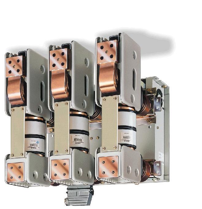
13 Description Construction The vacuum circuit-breaker consists of the mechanism housing (60) the 3-pole assemblies (19) with vacuum interrupter (30) cast-resin post insulators (161and 162) struts (282 and 283) and of the operating rods (48) Each of three pole assemblies (19) is supported by two cast-resin post insulators (161and 162) which are bolted to the traverses (141 and 142) respectively The main features of the vacuum circuit-breaker are shown in Fig2/1 (60) 3 (19) (30) ( ) ( ) and (48) (19) ( ) ( ) 2/1 Fig2/1 vacuum circuit-breaker 2/1 The mechanism housing (60) accommodates all electrical and mechanical elements required for opening and closing the vacuum circuit-breaker Fig 2/2 shows the arrangement of the individual modules in the mechanism housing On vacuum circuit-breakers with pole assemblies as illustrated in Fig2/4 (page2/3) no opening spring (64) is required as the contact pressure spring (49) on this version perform an opening function The mechanism housing has a detachable cover 601(Fig2/3) This cover (601) has cutouts for the actuating and indicating devices The vacuum circuit-breaker is closed by means of the pushbutton (53) The motor (504) immediately recharges the closing spring (62) In the event of motor power supply failure the closing spring can be charged by means of a hand crank (50) The cover includes an opening (501) for the hand crank behind which the hand crank coupling (505) of the gearing (502) is located The stored-energy mechanism state is shown by the indicator (55) The indicator (59) shows the breaker state (ON-OFF) The operating cycle counter (58) indicates the number of charging operations The rating plate (51) is attached to the mechanism housing but visible through an opening (511) in the cover The movement is transmitted to the pole assemblies via moulded-plastic operating rods (48) (60) 2/2 2/4 (2/3 ) (64) (49) 601( 2/3) (601) (53) (504) (62) (50) (501) (502) (505) (55) (59) ( - ) (58) (51) (511) (48) - 2/1 - Operating Instruction Siemens /
14 Fig 2/2 View of an open mechanism housing 2/2 Fig 2/3 Actuating and indicating devices 2/3-2/2 - Operating Instruction Siemens /
15 There are two pole assembly versions for the vacuum circuit-breaker each depending on the rated normal current and on the rated short-circuit breaking current (see Fig 2/4 and 2/5) ( 2/4 2/5) Fig 2/4 pole assembly 2/4 Fig 2/5 pole assembly 2/5-2/3 - Operating Instruction Siemens /
16 Vacuum interrupters The basic construction of the vacuum interrupters for the vacuum circuit-breaker is shown in the sectional view in Fig2/6 Depending on its type the vacuum interrupter (30) is fixed to the upper interrupter support (20) The fixed contact piece (31) is connected directly with the housing The moving contact piece (36) is fixed to the terminal bolt (361) and is located centrally in the guide (35) The metal bellows (34) for the vacuum-proof connection to the interrupter housing 2/6 (30) ( ) (20) (31) (36) (361) (35) (34) Fig2/6 vacuum interrupter 2/6 The vacuum interrupters fitted in the vacuum circuit-breaker are type-approved in accordance with the X-ray regulations of the Federal Republic of Germany They conform to the requirements of the X- ray regulations of January (Federal LAW Gazette Page 144) 8 and annex section 5 up to rated short-time AC voltage stipulated in accordance with DIN VDE/IEC X ( 144 ) 5 8 DIN VDE/IEC X - 2/4 - Operating Instruction Siemens /
17 Complement The basic version of the vacuum circuit-breaker comprises: Electrical operating mechanism (charging motor) With mechanical and electrical anti-pumping feature (M1) Closing solenoid (Y9) Shunt release (Y1) Low-voltage plug connector 64-pole (X0) with grommet sleeve housing Auxiliary switch 6NO+6NC (S1) Position switch for signaling "Closing spring charged" (S41 S42) Breaker tripping signal cut-out switch (S6 S7) Operating cycle counter Each vacuum circuit-breaker can be equipped with the following supplementary devices: Extended auxiliary switch 12NO+12NC (S1) Shunt release 3AX1101 (Y2) Current transformer-operated release 3AX1102 (Y4) Undervoltage release 3AX1103 (Y7) Electrical manual closing (S14 S15) Electromechanical interlock (S12) In addition to the standard shunt release Y1 the vacuum circuit-breaker can be fitted with a maximum of two release of type 3AX 11 The permissible combination of supplementary equipment and special versions are stated in catalogue HG 11 ( ) : (M1) (Y9) 1 (Y1) 64 (X0) 6 +6 (S1) " " (S41 S42) (S6 S7) : (S1) 2 3AX1101 (Y2) 3AX1102 (Y4) 3AX1103 (Y7) (S14 S15) (S12) Y1 3AX 11 HG 11-2/5 - Operating Instruction Siemens /
18 Installation Installing in cubicle or on truck The vacuum circuit-breaker are supplied in the open state with the closing spring discharged indication (55) visible Before installing the V- breaker remove the transport device (skids and spacers) Mount face loose supplied phase barrier in accordance with the supplied drawings 3AH (55) ( ) Before installing the vacuum circuit-breaker in a cubicle or a truck check its rating plate data (to avoid confusion) and compare the rated voltage indicated in the delivery papers with the power supply voltage available at the site On the vacuum circuit-breaker with undervoltage release (Y7) 3AX1103 the arresting screw of the hammer must be moved from position A to B (see annex to operating instructions for release or note card in mechanism housing [60] of vacuum circuit-breaker) ( ) (Y7) 3AX1103 A B ( (60) The mechanism housing has six fixing holes - two at the top and four at the bottom-to suit the various types of installation (Fig3/1) Use at least four M12 fixing bolts of strength class ( 3/1) M12 8 When installing the breaker in a rack or flame the four lugs (143) supplied as loose ite may also be used Eight M12 fixing bolts of strength class 8 must be used here The rack or frame must be adapted to the operating conditions and have adequate load bearing capacity and stability ) (143) 8 M12 8 View Y/ Y ( Fig3/1 Means of fixing vacuum circuit-breaker 3/1 View Z/ Z Flat bar connection Prior to fitting the conductors fix them so as to ensure smooth contact with their connecting parts and with the holes in full alignment Rub the contact faces to be bolted together with crisscrossing strokes using a wire brush until bright metal shows and wipe then with a clean rag Note! Copper-sprayed and spray silver-plated surfaces should be cleaned a rag and not brushed! - 3/1 - Operating Instruction Siemens /
19 Differing contact materials (AL/CU) must not be worked with the same cleaning tool Thinly grease the bright contact faces with acid-free Vaseline (eg Shell Vaseline 8420) and bolt them together immediately 1 ) ( / ) ( Shell 8420) 1 ) Use the appropriate M12 nuts and bolts of strength class 8 and corresponding spring elements and plain washers 8 M12 Note! When tightening the terminal screws counteract the torque (70Nm~7mkp) by resisting it with a suitable spanner or socket wrench Control leads Vacuum circuit-breaker of standard design are provided with a 64-pole low-voltage plug connector X0 (6871) The corresponding plug for external connection is designed for crimp connection of control leads with a nominal section area of 15mm 2 Use only crimping tools (eg Harting crimp tongs with positioning sleeve ) 2 ) Make reference to the circuit diagram supplied! 70Nm~7mkp 64 X0 (6871) 15mm 2 ( Harting ) 2 ) Earthing Connect the vacuum circuit-breaker to the appropriate high voltage protective earth by means of the suitable marked M12 (70) terminal on the top of the mechanism housing (60) using flat copper copper cable or hot galvanized steel strip (DIN VDE 0141/776 Item 53) M12 (70) (DIN VDE 0141/776 53) (60) Circuit documents The wiring and connection of circuit-breaker is shown in the circuit diagram supplied depending on the particular model and complement Typical circuit diagram for circuit-breaker are shown in Fig 3/2 and 3/4 3/2 3/4 1 ) Shell Vaseline 8420 Deutsche Shell AG Abt VSM Überseering Hamburg Postfach ) Harting Crimpzange Harting Elektronic GmbH Marienwerder stra e Espelkamp Postfach /2 - Operating Instruction Siemens /
20 Function schematic diagram Release "off" " Motor drive Closing and antipumping device 1 st shunt release Switch tripping signal closing spring charged signal Fig3/2 V circuit-breaker with mechanical manual and electrical closing with 64-way plug connector 3/2 64 System wiring Breaker wiring System wiring Tripping via NC contact Tripping via NC contact HA HE K1 Manual tripping/ Manual closing/ Anti-pumping contactor M1 Motor operating mechanism/ P Energy store/ R1 Resistor/ S1 Auxiliary switch/ S21 S22 Position switches (cut-out motor after charging) ( ) S3 Position switch (opens when closing spring charged ) ( ) S41 S42 Position switch (signals charged state) ( ) S6 S7 Position switch (for switch tripped signal) ( ) X0 Low-voltage plug connector/ Y1 1 st shunt release/ Y2 2 nd shunt release/ Y7 Undervoltage release/ Y9 Closing solenoid/ S10 S11 Position switches (mech Pumping prevention) ( ) Fig3/3 Typical circuit for connection of the undervoltage release Y7 Function 3/3 schematic diagram Y7-3/3 - Operating Instruction Siemens /
21 Function schematic diagram Extended auxiliary switch Release "off" " Motor drive Electrical manual closing -Y6 -Y5 -Y7 Closing and antipumping device 1 st shunt release 1 st CT operated release Switch tripping signal Closing spring charged signal Fig3/4 V circuit-breaker with electrical manual closing with 64-way plug connector Example for extended fitting with Y4 and varistor circuit for DC 3/4 64 Y4 With this model the auxiliary switch terminals are wired to the plug connector as illustrated Auxiliary switch standard Auxiliary switch extended HA HE K1 Manual tripping/ Manual closing/ Anti-pumping contactor M1 Motor operating mechanism/ P Energy store/ R1 Resistor/ S1 Auxiliary switch/ S21 S22 Position switches (cut-out motor after charging) ( ) S3 Position switches (open when closing spring charged ) ( ) S41 S42 Position switches (signals charged state) ( ) S6 S7 Position switches (for switch tripped signal) ( ) X0 Low-voltage plug connector D7 B3 B8 C5 D8 D9 B9 C9 Wiring not applicable if B Y2 (2 nd shunt release) fitted E Y7 (undervoltage release) fitted B 2 Y2 E Y7 Y1 1 st shunt release/ Y2 2 nd shunt release/ Y4 CT operated release/ Y7 Undervoltage release/ Y9 Closing solenoid/ S10 S11 Position switches (mech pumping prevention) ( ) V1 V2 Varistor module/ - 3/4 - Operating Instruction Siemens /
22 ! DANGER! High voltage! touching of live will result in death or severe personal injury! This equipment shall be operated only by qualified personal after becoming thoroughly familiar with the respective instruction manual and in particular all safety instruction! WARNING! This equipment contains hazardous voltages and mechanical parts which move at high speed and may be control remotely Non-observance of the safety instructions can result in severe personal injury or property damaged In particular: Do not remove the cover (601) Do not reach inside any openings in the operating mechanism Dot not touch pole assemblies (19) and operating rods (48) : (601) (19) (48) Commissioning Prior to commissioning check the V-breaker in accordance with the following points: 1 Clean them as applicable (for details refer to cleaning page 5/1) 2 Check all fixing and terminal screws for tightness 3 Examine the circuit-breaker for any external damage especially to the control leads post insulators and interrupters 1 ( 5/1) 2 3 :! CAUTION! The V-breaker may be operated only with the original hand crank (50) in order to avoid injures as a result of the motor suddenly starting up (50) 4 Charge the closing spring (62) with the hand crank (50) (see Fig4/1) press the close push-button (53) and after closing trip the breaker by pressing the open push-button (54) 4 (50) (62) ( 4/1) (53) (54) - 4/1 - Operating Instruction Siemens /
23 On the V-breaker with undervoltage release (Y7) 3AX1103 the arresting screw of the hammer must be moved from position A to B 5 For test operations with the motor mechanism switch on the supply voltage The motor will start immediately and charge the closing spring (62) check the mechanical and electrical indication of the charging state of the closing spring actuate the mechanism as indicated under 4 And check the mechanical and electrical state indication (Y7) 3AX1103 A B 5 (62) 4 6 Check the auxiliary switch S1 (68) and position switches (5041) electrically in both end positions by actuating the vacuum circuit-breaker 6 S1 (68) (5041) 7 Also check-by electrical actuation the function of the closing solenoid Y9 (531) and all fitted shunt release 8 The cover (601) of the mechanism housing is fixed by four bolts (6011) When commissioning check that a tightening torque of 10Nm has been observed When correct functioning of the V-breaker has been ascertained it can be put into service Charging the closing spring When the supply voltage is applied the motor (504) automatically charges the closing spring (62) Should the supply fail the closing spring (62) can also be charged by hand crank (50) In the lattercase as shown in Fig 4/1 The hand crank is inserted with the forwards pushed adapter (506) through the opening (501) onto hand crank coupling (505) and turned clockwise until the symbol "closing spring discharged shown in the indicator opening (553) is changed to "closing spring charged (Fig 4/2) The adapter (506) is designed so that the hand crank (50) is decoupled on the recovery of the motor supply 7 Y9 (531) 8 (601) (6011) 10Nm (504) (62) (50) 4/1 (50) (506) (501) (505) (553) ( 4/2) (506) Fig4/1 Charging the closing spring with the hand crank 4/ /2 - Operating Instruction Siemens /
 After closing (and if applicable releasing of the close push-button (53) the closing spring (62) is immediately and automatically recharged the \"closing spring charged (55)")
24 Closing If operation is not blocked by the mechanical interlock press the close push-button (53) or the corresponding control switch until the vacuum circuitbreaker closes and both indicates and signals this state (53) After closing (and if applicable releasing of the close push-button (53) the closing spring (62) is immediately and automatically recharged the "closing spring charged (55) and indication becomes visible once again ( (53) ) (62) (55) Tripping The opening spring (64) is charged during closing (64) To trip the breaker press the open push-button (54) or corresponding control switch until the V-breaker trips and both indicates and signals this state (54) Fig4/2 Closing spring discharged 4/2 Closing spring charged - 4/3 - Operating Instruction Siemens /
25 Maintenance Safety measure! DANGER! Maintenance repair and subsequent conversion work may be carried out only by specially trained personnel in accordance with the operating instructions and/or special conversion instructions Training and information sessions for personnel can be provided by the competent Siemens department before starting any work on V-breakers reference must be made to the local safety regulations for high-voltage switchgear eg the five safety rules (DIN VDE 0105/0783 Part 1 item 9) Switch off the power supply and then close and open the V-breaker by hand ( V-breaker in open state "closing spring discharged" indication visible) in order to ensure that the closing spring is discharged Non-observation can result in death severe personal injure or substantial property damage (DIN VDE 0105/ ) ( " " ) Servicing Under normal operating conditions the vacuum circuit-breaker is maintenance-free We recommend nonetheless a regular visual inspection Cleaning To ensure the insulating capacity It is necessary that the insulating component are clean Insulating components and external breaker parts must be wiped with a damp cloth Use only warm water with the addition of a mild liquid household detergent as cleaning agent! WARNING! Windings and terminals must not be touched if the power supply has not been disconnected Non-observance can result in death or serious personnel injury! CAUTION! All springs of the operating mechanism must be relaxed and the vacuum circuit-breaker be brought into the open state "closing spring discharged" indication visible Non-observance can result in personnel injury " " - 5/1 - Operating Instruction Siemens /
26 Abnormal conditions If the vacuum circuit-breaker is used in abnormally unfavourable indoor conditions (eg frequent heavy condensation dust-ridden air etc) We recommend regular cleaning of the breaker external components and if necessary renewal of the anti-corrosion protection Only the following products may be used for the respective working parts of the VCB Bearing sliding surface: Isoflex Topas L32 Kl ber- Lubrication KG Geisenhausener Strasse 7 Postfach Munich Federal Republic of Germany ( ) : Isoflex Topas L32 Kl ber- Lubrication KG Geisenhausener Strasse 7 Postfach Munich Federal Republic of Germany Bearings inaccessible to grease and bearings of the auxiliary switch S1: SHELL Tellus Oil 32 SHELL oil trade company GmbH Zitadellenstrasse 5 POBox Hamburg Federal Republic of Germany Joints and bearings which cannot be dismantled must not be treated with a cleaning agent prior to reapplication of anti-corrosives SHELL Tellus Oil 32 SHELL oil trade company GmbH Zitadellenstrasse 5 POBox Hamburg Federal Republic of Germany S1 : After renewal of the anti-corrosion protection several mechanical test-switching operations should be performed on the vacuum circuit-breaker Lubricants (for special conditions) are available from the Siemens agent responsible: ( ) : Order No 180 g Kl ber-isoflex topas L32 3AX1133-3A and 50 g SHELL Tellus Oil g Kl ber-isoflex topas L32 3AX1133-3H 50 g SHELL Tellus Oil 32 3AX1133-2G 180 g Kl ber-isoflex topas L32 3AX1133-3A and 50 g SHELL Tellus Oil g Kl ber-isoflex topas L32 3AX1133-3H 50 g SHELL Tellus Oil 32 3AX1133-2G 1kg SHELL Tellus Oil 32 3AX1133-2D 1kg SHELL Tellus Oil 32 3AX1133-2D 1kg Kl ber-isoflex Topas L32 3AX1133-3E 1kg Kl ber-isoflex Topas L32 3AX1133-3E - 5/2 - Operating Instruction Siemens /
27 Checking the contact system The contact system is subject to wear both by contact erosion and by compression of the contact pieces and the guide bolts To check the contact wear a marking is provided on the lower interrupter support (Fig 5/1) The position of the indicator (10) relative to the stripe (101) in closed state indicates changes in the contact system The breaker may be operated only when the indicator is within the range of the stripe ( 5/1) (10) (101) Fig5/1 Check mark Checking the vacuum Such a check should be made if there is any risk of an interrupter having developed a leak Busbar and cable connections must be split The check is performed with an HV test unit If necessary further information may be obtained from the appropriate Siemens Regional Office Service life of vacuum interrupter The maximum permissible number of mechanical operating cycles is The permissible number of operating cycles as a function of the breaking current is shown in Fig5/2 When this permissible maximum has been attained the interrupters or the complete pole assemblies (depending on the version) must be renewed Detailed instructions are supplied with the replacement interrupters/pole assemblies When ordering replacement interrupters or pole assemblies state the circuit-breaker type design code and serial number (see name plate) /2 ( ) / / ( ) - 5/3 - Operating Instruction Siemens /


 Breaking current/ (ka) break operations/ break operations/ break operations/ break")

28 Determination of the load characteristic number/ Rated voltage Rated short-circuit breaking current Load characteristic number at rated normal current kv ka 800A 1250A 2000A 2500A 3150A Breaking current/ (ka) Breaking current/ (ka) break operations/ break operations/ break operations/ break operations/ 4 5 Breaking current/ (ka) Breaking current/ (ka) Permissible number of operating cycle as a function of breaking current In In - 5/4 - Operating Instruction Siemens /
29 Accessories and spare parts A hand crank 3AX B for charging the closing spring can be supplied as an accessory: Owing to the fact that all parts of this breaker type have been optimized to the last the normal service life it is not possible to recommend particular spare parts for keeping in stock When ordering spare part state the following: 1 Type designation design code and serial number of the vacuum circuit-breaker (see rating plate) 2 The designation and part number making reference to illustrations in these operating instructions or to a photograph or sketch as applicable Alternatively a sample may be submitted 3AX B : : 1 ( ) 2 Published by the Power Transmission and Distribution Group Schaltwerk Berlin Translated by SLC PTD MC Edition 1/March 2001 Schaltwerk 01/3 /2001 Subject to change - 5/5 - Operating Instruction Siemens / Order No / Place of order / : 3ZX1812-0AH10-0AN2 / SLC PTD MC : SLC PTD MC ShangHai
3AK OPERATING INSTRUCTIONS. Vacuum circuit-breaker module 3AK1 and 3AK3
 3AK Vacuum circuit-breaker module 3AK1 and 3AK3 OPERATING INSTRUCTIONS Order no.: 9229 9923 176 0B Ordering location: IC LMV LP PO P C41 AG 09.2013 en Siemens AG 2006. All rights reserved. For your safety
SION Vacuum Circuit-Breakers. Answers for energy. Medium-Voltage Equipment Selection and Ordering Data. Catalog HG
 Medium-Voltage Equipment Selection and Ordering Data Catalog HG 11.0 008 Answers for energy. R-HG11-17.tif Siemens HG 11.0 008 Contents Contents Page SION Vacuum Circuit-Breakers Description General Construction
Siemens AG Catalog HG11.07 Edition 10/ AE6 Medium-Voltage Equipment. siemens.com/sion
 Siemens AG 2018 Catalog HG11.07 Edition 10/ 2018 SION Lateral Vacuum Circuit-B Breaker with Laterrall Operating Mechaniism m 3AE6 Medium-Voltage Equipment siemens.com/sion 2 Catalog HG11.07 10 / 2018 SION
SION Vacuum Circuit-Breakers. Answers for energy. Medium-Voltage Equipment Selection and Ordering Data. Catalog HG
 Medium-Voltage Equipment Selection and Ordering Data Catalog HG 11.02 2011 Answers for energy. R-HG11-172.tif 2 Siemens HG 11.02 2011 Contents SION Vacuum Circuit-Breakers Medium-Voltage Equipment Catalog
Vacuum Circuit-Breaker Modules
 Vacuum s Medium-Voltage Equipment Catalog HG.5 998 Vacuum s Medium-Voltage Equipment Description Catalog HG.5 998 Siemens AG 998 NXACT Vacuum vacuum circuit-breaker module, kv Features DIN EN ISO 900
SION OPERATING INSTRUCTIONS. Vacuum circuit-breakers kv, ka kv, 40 ka 24 kv, ka
 SION Vacuum circuit-breakers 7.2 17.5 kv, 12.5 31.5 ka 7.2 17.5 kv, 40 ka 24 kv, 12.5 25 ka OPERATING INSTRUCTIONS Order no.: 9229 0001 176 0G Ordering location: EM LP IEC PRM MVP AG 09.2015 en Siemens
Benefits, typical uses
 R-HA26-013. eps Switchgear Type 8BT1, up to 24kV,Air-Insulated Contents Application Page Application Benefits 2 Typical uses 2 and 3 Technical Data Ratings 4 Classification, dimensions, 5 room planning
3TM Vacuum Contactors
 Catalog Extract HG 11.23 Edition 2016 Catalog Extract Medium-Voltage Equipment siemens.com/3tm R-HG11-343.psd 2 Siemens HG 11.23 2016 Contents Medium-Voltage Equipment Catalog Extract HG 11.23 2016 Contents
Fixed-Mounted Circuit-Breaker Switchgear Type NXPLUS C up to 24 kv, SF 6 -Insulated. Medium-Voltage Switchgear Catalog HA 35.
 Fixed-Mounted Circuit-Breaker Switchgear Type NXPLUS C up to kv, SF 6 -Insulated Medium-Voltage Switchgear Catalog HA 5. 00 Invalid: Catalog HA 5. 00 R-HA5-05 eps Fixed-Mounted Circuit-Breaker Switchgear
Vacuum Circuit-Breakers, Type HVX kv, of cassette design, cassette with motor drive
 Vacuum Circuit-Breakers, Type HVX 12 24 kv, of cassette design, cassette with motor drive Operating Instructions No. 531 321, Edition 09/00 Table of Contents 1 General 4 1.1 Operating Conditions 4 2 Design,
Rated voltage 12 kv to 38.5 kv Rated current 630 A to 2500 A
 KUF DRIESCHER Indoor Vacuum CircuitBreaker voltage to.5 kv current to 00 A 4kV 746 Get connected http://www.driescher.com V6 ELEKTROTECHNISCHE WERKE FRITZ DRIESCHER & SÖHNE GMBH D8566 MOOSBURG TEL. +49
Type SIMOPRIME A4, up to 24 kv, Air-Insulated Medium-Voltage Switchgear
 Circuit-Breaker www.siemens.com/energy Switchgear Type SIMOPRIME A4, up to 24 kv, Air-Insulated Medium-Voltage Switchgear s Technology Circuit-Breaker Switchgear Type SIMOPRIME, up to 17.5 kv, Air-Insulated
Switchgear Type 8BT1, up to 24 kv, air-insulated. Medium Voltage Switchgear Catalog HA 26.
 www.siemens.com/medium-voltage-switchgear Switchgear Type 8BT1, up to 24 kv, air-insulated Medium Voltage Switchgear Catalog HA 26.31 2012 Answers for infrastructure and cities. R-HA26-013. eps Contents
1. Safety practices General Introduction Standards...3
 1. Safety practices...2 2. General...3 2.1 Introduction...3 2.2 Standards...3 3. Technical data...3 3.1 Designation...3 3.2 Electrical ratings and dimensions...4 3.3 Fixation...6 3.4 Connecting terminals...6
Fixed-Mounted Circuit-Breaker Switchgear Type 8DA and 8DB up to 40.5 kv, Gas-Insulated
 www.siemens.com/medium-voltage-switchgear Fixed-Mounted Circuit-Breaker Switchgear Type 8D and 8DB up to 0.5 kv, Gas-Insulated Medium-Voltage Switchgear Catalog H 35.11 201 nswers for infrastructure and
Circuit-Breaker Switchgear Type SIMOPRIME, up to 17.5 kv, Air-Insulated Medium-Voltage Switchgear.
 Circuit-Breaker Switchgear Type SIMOPRIME, up to 17.5 kv, Air-Insulated Medium-Voltage Switchgear www.siemens.com/energy Technology s Contents Application Page Benefits 2 Typical uses 2 and 3 Technical
Retrofit for gas-insulated high voltage switchgear (GIS) - 8D1 and 8D2
 - 8D1 and 8D2") Retrofit for gas-insulated high voltage switchgear (GIS) - 8D1 and 8D2 Table of Contents 1 Introduction... 4 2 Description of retrofit circuit-breaker 8DN8... 5 3 Technical data for retrofit circuit-breaker
Retrofit for gas-insulated high voltage switchgear (GIS) - 8D1 and 8D2 Table of Contents 1 Introduction... 4 2 Description of retrofit circuit-breaker 8DN8... 5 3 Technical data for retrofit circuit-breaker
Switchgear Type 8DJH for Secondary Distribution Systems up to 24 kv, Gas-Insulated
 Switchgear Type 8DJH for Secondary Distribution Systems up to 24 kv, Gas-Insulated Medium-Voltage Switchgear Catalog HA 40.2 2009 Answers for energy. -HA40-111.eps -HA40-110.eps -HA40-109.eps -HA40-112.eps
Outdoor live tank vacuum circuit breaker Type OVB-VBF for 24/36/40.5 kv applications
 Outdoor live tank vacuum circuit breaker Type OVB-VBF for 24/36/40.5 kv applications ABB a global leader ABB is a global leader in power and automation technologies that enable utility and industry customers
Medium-Voltage Switchgear OPERATING INSTRUCTIONS
 Medium-Voltage Switchgear Circuit-Breaker Switchgear Type NXAIR: Factory-Assembled, Type-Tested and Metal- Enclosed Switchgear for Indoor Installation, Air-Insulated Loss of Service Continuity Category:
8BK80 Genuine metal-clad single busbar switchgear with Vacuum Circuit Breaker on withdrawable truck upto 36kV
 8BK80 Genuine metal-clad single busbar switchgear with Vacuum Circuit Breaker on withdrawable truck upto 36kV Fully Typed Tested including Internal Arc Test s Switching Device Compartment for Partners
NXPLUS C Single busbar. Maintenance-free for lifetime
 NXPLUS C Single busbar Maintenance-free for lifetime Energy Distribution Welcome! Page 2 Content Overview Technical data Typicals Panel design Circuit-Breaker panel Busbar Operation Metering Low-voltage
High-Voltage Circuit-Breakers 3AP1/ kv up to 550 kv. Power Transmission and Distribution
 High-Voltage Circuit-Breakers AP/ 7.5 kv up to 550 kv Power Transmission and Distribution The AP/ High-Voltage Circuit-Breakers Now Applicable for 550 kv Decades of our experience in high-voltage switching
DISTRIBUTION SOLUTIONS. GSec Gas-insulated switching and isolating apparatus
 DISTRIBUTION SOLUTIONS GSec Gas-insulated switching and isolating apparatus GSec is a three-position SF6 gas-insulated switchdisconnector designed for use in medium voltage switchgear for secondary distribution
Fixed-Mounted Circuit-Breaker Switchgear Type 8DA and 8DB up to 40.5 kv, Gas-Insulated
 Fixed-Mounted Circuit-Breaker Switchgear Type 8D and 8DB up to 0.5 kv, Gas-Insulated Medium-Voltage Switchgear Catalog H 35. 00 nswers for energy. R-H35-30.eps pplication Public power supply system R-H35-3.eps
3 - Protection components Motor circuit-breakers
 Contents 0 - Protection components Motor circuit-breakers protection components for the motor protection Thermal-magnetic motor circuit-breakers Selection guide..............................................page
Earthing Switch Class B Hochspannungstechnik Peters & Thieding GmbH
 Peters& Thieding Hochspannungstechnik GmbH Earthing Switch Class B Hochspannungstechnik Peters & Thieding GmbH OVERVIEW The PTE earthing switch is an indoor switching device for installation in air-insulated
All rights reserved. Neither this catalogue nor any part of it may be copied using any method or for any purposes. Most studies are legally protected.
 Issued: January 2013 Copyright by ZPUE Katowice S.A. All rights reserved. Neither this catalogue nor any part of it may be copied using any method or for any purposes. Most studies are legally protected.
Instruction manual. EK6 Earthing switch 36/40.5 kv
 Instruction manual EK6 Earthing switch 36/40.5 kv Your safety first always! That s why our instruction manual begins with these recommendations: Only install switchgear and/or switchboards in enclosed
EISHO TEK. Vacuum Circuit Breaker
 EISHO TEK Vacuum Circuit Breaker TYPE:SV1-12 INSTRUCTION MANUAL Operation and Maintenance Version TAIWAN CALSONIC SAFETY PRECAUTIONS For safety reason, this equipment should be handled by personnel who
Switchgear Type 8DJH for Secondary Distribution Systems up to 24 kv, Gas-Insulated
 Switchgear Type 8DJH for Secondary Distribution Systems up to 24 kv, Gas-Insulated Medium-Voltage Switchgear Catalog HA 40.2 2010 Answers for energy. -HA40-110.eps -HA40-109.eps -HA40-112.eps -HA40-111.eps
Gas-Insulated Switchgear. Type 8VN1 blue GIS up to 145 kv, 40 ka, 3150 A
 Gas-Insulated Switchgear Type 8VN1 blue GIS up to 145 kv, 40 ka, 3150 A siemens.com/energy-management Table of content Gas-insulated switchgear Product portfolio 72.5 550 kv Vacuum interrupters for switching
HB3-80 Generator Circuit-Breaker Switchgear. Medium-Voltage Switchgear. Totally Integrated Power HB3-80. Catalog HB3-80.
 HB3-80 Generator Circuit-Breaker Switchgear Medium-Voltage Switchgear Totally Integrated Power HB3-80 Catalog HB3-80 Edition 2014 www.siemens.com/generatorswitchgear R-HB1-001.tif R-HB3-001.tif R-HB3-003.tif
Fixed-Mounted Circuit-Breaker Switchgear Type NXPLUS up to 40.5 kv, Gas-Insulated
 www.siemens.com/medium-voltage-switchgear Fixed-Mounted Circuit-Breaker Switchgear Type NXPLUS up to 40.5 kv, Gas-Insulated Medium-Voltage Switchgear Catalog HA 35.5 203 Answers f infrastructure and cities.
Horizontal Circuit Switchers
 > Transformer Protection > CIRCUIT SWITCHERS C A T A L O G B U L L E T I N General Application Southern States Types CSH and CSH-B Horizontal Circuit Switchers provide an economical, versatile, space saving
HB3 Generator Circuit-Breaker Switchgear
 Catalog HB3 Edition 2017 HB3 Generator Circuit-Breaker Switchgear Medium-Voltage Switchgear siemens.com/generatorswitchgear R-HB1-001.tif R-HB3 001.tif R-HB3 003.tif R-HB3 002.jpg 2 HB3 Generator Circuit-Breaker
User manual W-VACi. W-VACi 12 / 17.5 / 24 kv IEC Vacuum Circuit Breakers
 User manual W-VACi W-VACi 12 / 17.5 / 24 kv IEC Vacuum Circuit Breakers 65A7355H01 Rev.04 January 2013 www.eaton.com 2 Table of contents 1 Safety... 5 1.1 Safety precautions...5 1.2 Safety practices...5
HVX Vacuum circuit-breaker kv ( 2500 A, 40 ka)
") MEDIUM VOLTAGE SWITCHING DEVICE HVX Vacuum circuit-breaker 12-24 kv ( 2500 A, 40 ka) Installation Operation Maintenance 0 HVX No. AGS 531 301-01 Edition 07/07 Technical instruction AREVA T&D AREVA T&D
MEDIUM VOLTAGE SWITCHING DEVICE HVX Vacuum circuit-breaker 12-24 kv ( 2500 A, 40 ka) Installation Operation Maintenance 0 HVX No. AGS 531 301-01 Edition 07/07 Technical instruction AREVA T&D AREVA T&D
BHARAT HEAVY ELECTRICALS LIMITED, JHANSI
 BHARAT HEAVY ELECTRICALS LIMITED, JHANSI DESIGN, MANUFACTURING, TESTING, SUPPLY INSTALLATION AND COMMISSIONING OF 11KV VACUUM CIRCUIT BREAKER NOTE : 1 VENDOR must submit complete information against clause
MEDIUM VOLTAGE SWITCHING DEVICE. Vacuum circuit-breaker 17,5 kv (> 2500 A / 50 ka) Installation Operation Maintenance
 Installation Operation Maintenance") 0 MEDIUM VOLTAGE SWITCHING DEVICE HVX Vacuum circuit-breaker 17,5 kv (> 2500 A / 50 ka) Installation Operation Maintenance HVX No. AGS 531 461-01 Edition 06/07 Technical instruction AREVA T&D AREVA T&D
0 MEDIUM VOLTAGE SWITCHING DEVICE HVX Vacuum circuit-breaker 17,5 kv (> 2500 A / 50 ka) Installation Operation Maintenance HVX No. AGS 531 461-01 Edition 06/07 Technical instruction AREVA T&D AREVA T&D
SUBSTATION VACUUM CIRCUIT BREAKER (38KV)
") SUBSTATION VACUUM CIRCUIT BREAKER (38KV) For more than four decades, Myers Power Products has led the switchgear market in quality for the electric industry, delivering highly reliable products for utilities
SUBSTATION VACUUM CIRCUIT BREAKER (38KV) For more than four decades, Myers Power Products has led the switchgear market in quality for the electric industry, delivering highly reliable products for utilities
SUBSTATION VACUUM CIRCUIT BREAKER (15.5KV)
") SUBSTATION VACUUM CIRCUIT BREAKER (15.5KV) For more than four decades, Myers Power Products has led the switchgear market in quality for the electric industry, delivering highly reliable products for utilities
SUBSTATION VACUUM CIRCUIT BREAKER (15.5KV) For more than four decades, Myers Power Products has led the switchgear market in quality for the electric industry, delivering highly reliable products for utilities
SUBSTATION VACUUM CIRCUIT BREAKER (25.8 / 27KV)
") SUBSTATION VACUUM CIRCUIT BREAKER (25.8 / 27KV) For more than four decades, Myers Power Products has led the switchgear market in quality for the electric industry, delivering highly reliable products
SUBSTATION VACUUM CIRCUIT BREAKER (25.8 / 27KV) For more than four decades, Myers Power Products has led the switchgear market in quality for the electric industry, delivering highly reliable products
VD4. Installation and service instructions kv A ka
 VD4 Installation and service instructions 12... 24 kv - 630... 2500 A - 16... 31.5 ka For your safety! Make sure that the installation room (spaces, divisions and ambient) is suitable for the electrical
Vacuum Circuit Breaker (Vehicle)
") Vacuum Circuit Breaker (Vehicle) Type 5 HVU-250 4.76kV Instructions Installation Operation Maintenance SGIM-9998A Hazardous voltages and high-speed moving parts. Will cause death, serious injury or equipment
Vacuum Circuit Breaker (Vehicle) Type 5 HVU-250 4.76kV Instructions Installation Operation Maintenance SGIM-9998A Hazardous voltages and high-speed moving parts. Will cause death, serious injury or equipment
BETA Switching Switches and Light Indicators
 Siemens AG 2008 BETA Switching /2 Product overview /3 5TE8 control switches / 5TE4 pushbuttons /2 5TE5 light indicators /5 5TE8 ON/OFF switches /22 5TE9 busbars /24 5TE switch disconnectors Siemens ET
24 k B788 ELEKTROTECHNISCHE WERKE FRITZ DRIESCHER & SÖHNE GMBH
 788 Instructions for Installation, Operation and Maintenance for DRIESCHER - Air - Insulated Medium - Voltage Compact Switchgears for Substations Rated voltage 12 kv and 24 kv Rated current 630 A 24 k
Type SDV6 distribution circuit breaker. Top performance - proven reliability. Answers for energy.
 Type SDV6 distribution circuit breaker Top performance - proven reliability Answers for energy. Table of contents Introduction 2-4 Type 3AH3 stored-energy operating mechanism 6 Vacuum interrupters 7 Ratings
GMA. Medium-voltage switchgear
 Medium-voltage switchgear Gas-insulated switchgear up to 24 kv - 2500 A - 31.5 ka Earthing without automatically CLOSE / OPEN of the Circuit Breaker Operation - Maintenance Technical Manual No. AGS 531
HVX. Vacuum circuit-breaker kv ( 2500 A, 40 ka) Installation Operation Maintenance. No. AGS Issue 06/06. Technical instruction
 Installation Operation Maintenance. No. AGS Issue 06/06. Technical instruction") MEDIUM VOLTAGE SWITCHING DEVICE MEDIUM VOLTAGE SWITCHGEAR HVX Vacuum circuit-breaker 2-24 kv ( 2500 A, 40 ka) Installation Operation Maintenance HVX 0 No. AGS 53 30-0 Issue 06/06 Technical instruction
MEDIUM VOLTAGE SWITCHING DEVICE MEDIUM VOLTAGE SWITCHGEAR HVX Vacuum circuit-breaker 2-24 kv ( 2500 A, 40 ka) Installation Operation Maintenance HVX 0 No. AGS 53 30-0 Issue 06/06 Technical instruction
GE Consumer & Industrial Power Protection. New. SecoGear kV Metal-clad Switchgear. GE imagination at work
 GE Consumer & Industrial Power Protection New SecoGear 12-24kV GE imagination at work General SecoGear metal-clad switchgear is designed and manufactured with advance technology and has been comprehensively
Unified requirements for systems with voltages above 1 kv up to 15 kv
 (1991) (Rev.1 May 2001) (Rev.2 July 2003) (Rev.3 Feb 2015) (Corr.1 June 2018) Unified requirements for systems with voltages above 1 kv up to 15 kv 1. General 1.1 Field of application The following requirements
Medium-Voltage Switchgear INSTALLATION AND OPERATING INSTRUCTIONS
 Medium-Voltage Switchgear Type 8DA11 / 8DA12 Fixed-Mounted Circuit-Breaker Switchgear up to 27.5 kv, extendable 1/2-Pole Switchgear for AC Traction Power Supply Medium-Voltage Switchgear INSTALLATION AND
Switchgear Type SIMOSEC, up to 24 kv, Air-Insulated, Extendable
 www.siemens.com/medium-voltage-switchgear Switchgear Type SIMOSEC, up to 24 kv, Air-Insulated, Extendable Medium-Voltage Switchgear Catalog HA 41.43 2012 Answers for infrastructure and cities. Neue Bilder
Page. Circuit-Breakers M4 2 for motor protection. Auxiliary contacts 3 Signalling switch Auxiliary releases
 Circuit Breakers M4 Page Circuit-Breakers M4 2 for motor protection Auxiliary contacts 3 Signalling switch Auxiliary releases Insulated 3-pole busbar system 4 Terminal block DIN-rail adapters 5 Busbar
 medium voltage switchgear manufacturer VACUUM CIRCUIT-BREAKER SWITCHGEAR TYPE SIMOPRIME, UP TO 17.5kV, AIR INSULATED MEDIUM-VOLTAGE SWITCHGEAR. UNDER LICENSE BY SIEMENS. www.simosynergy.com/simoprime VACUUM
AF series contactors (9 2650)
") R E32527 R E39322 contactors General purpose and motor applications AF series contactors (9 2650) 3- & 4-pole contactors General purpose up to 2700 A Motor applications up to 50 hp, 900 kw NEMA Sizes 00
R E32527 R E39322 contactors General purpose and motor applications AF series contactors (9 2650) 3- & 4-pole contactors General purpose up to 2700 A Motor applications up to 50 hp, 900 kw NEMA Sizes 00
020: 2013 CEB SPECIFICATION MINIATURE CIRCUIT BREAKER (MCB)
") 020: 2013 CEB SPECIFICATION MINIATURE CIRCUIT BREAKER (MCB) CEYLON ELECTRICITY BOARD SRI LANKA Telephone: +94 11 232 0953 Fax: +94 11 232 3935 CONTENTS Page 1.0 Scope 3 2.0 System Parameters 3 3.0 Service
020: 2013 CEB SPECIFICATION MINIATURE CIRCUIT BREAKER (MCB) CEYLON ELECTRICITY BOARD SRI LANKA Telephone: +94 11 232 0953 Fax: +94 11 232 3935 CONTENTS Page 1.0 Scope 3 2.0 System Parameters 3 3.0 Service
Horizontal Circuit Switchers
 > Transformer Protection > CIRCUIT SWITCHERS C A T A L O G B U L L E T I N General Application Southern States Types CSH and CSH-B Horizontal Circuit Switchers provide an economical, versatile, space saving
SafeGear Motor Control Center Arc Resistant Metal-Clad Construction Brochure
 2017 SafeGear Motor Control Center Arc Resistant Metal-Clad Construction Brochure SafeGear Motor Control Center Arc resistant Metal-Clad construction Brochure Table of Contents 1. Description 1 1 2. SafeGear
013 : 2009 CEB SPECIFICATION MOULDED CASE CIRCUIT BREAKERS
 013 : 2009 CEB SPECIFICATION MOULDED CASE CIRCUIT BREAKERS FOR OVERHEAD NETWOKS CEYLON ELECTRICITY BOARD SRI LANKA Specification for MOULDED CASE CIRCUIT BREAKERS FOR OVERHEAD NETWOKS CEB Specification
33KV INDOOR SWITCHGEAR
 33KV INDOOR SWITCHGEAR September 2017 Engineering Department WEST BENGAL STATE ELECTRICITY TRANSMISSION COMPANY LIMITED Regd. Office: VidyutBhawan, Block DJ, Sector-II, Bidhannagar, Kolkata 700091. CIN:
GE Industrial Solutions. User/Installation Manual for 4.76kV -15kV SecoBloc
 GE Industrial Solutions User/Installation Manual for 4.76kV -15kV SecoBloc Index General Scope...3 Standards...3 Operating conditions...3 Technical specification...3 Basic structure Features...4 Operation...4
HVX. Vacuum circuit-breaker 12-17,5 kv ( 2500 A, 31,5 ka) Installation Operation Maintenance No. DRC NTV 142. Technical instruction.
 Installation Operation Maintenance No. DRC NTV 142. Technical instruction.") MEDIUM VOLTAGE SWITCHING DEVICE HVX Vacuum circuit-breaker 12-17,5 kv ( 2500 A, 31,5 ka) Installation Operation Maintenance No. DRC NTV 142 Issue 02/10 Technical instruction AREVA T&D IMPORTANT NOTE The
MEDIUM VOLTAGE SWITCHING DEVICE HVX Vacuum circuit-breaker 12-17,5 kv ( 2500 A, 31,5 ka) Installation Operation Maintenance No. DRC NTV 142 Issue 02/10 Technical instruction AREVA T&D IMPORTANT NOTE The
Medium-Voltage Switchgear INSTALLATION AND OPERATING INSTRUCTIONS
 Medium-Voltage Switchgear Type 8DB Extendable Fixed-Mounted Circuit-Breaker Switchgear up to 40.5 kv Double Busbar, Single-Pole Metal-Enclosed, Gas-Insulated Medium-Voltage Switchgear INSTALLATION AND
Voltage Rated operating voltage [kv] Rated power frequency withstand voltage [kv] Rated lightning impulse withstand voltage [kv]
![Voltage Rated operating voltage [kv] Rated power frequency withstand voltage [kv] Rated lightning impulse withstand voltage [kv]](/thumbs/80/82203973.jpg "Voltage Rated operating voltage [kv] Rated power frequency withstand voltage [kv] Rated lightning impulse withstand voltage [kv]") BasisBlock MC 1 Standards and Regulations IEC 62271-200 ; VDE 0671-200 ; BS EN 62271-200 Technical Data MC1-12 MC1-24 Voltage Rated operating voltage [kv] 12 24 Rated power frequency withstand voltage
BasisBlock MC 1 Standards and Regulations IEC 62271-200 ; VDE 0671-200 ; BS EN 62271-200 Technical Data MC1-12 MC1-24 Voltage Rated operating voltage [kv] 12 24 Rated power frequency withstand voltage
TECHNICAL SPECIFICATION OF 11KV SF6 / VCB METAL ENCLOSED, INDOOR (PANEL TYPE) / OUTDOOR RING MAIN UNIT (RMU). (IEC standard equipment)
 / OUTDOOR RING MAIN UNIT (RMU). (IEC standard equipment)") TECHNICAL SPECIFICATION OF 11KV SF6 / VCB METAL ENCLOSED, INDOOR (PANEL TYPE) / OUTDOOR RING MAIN UNIT (RMU). (IEC standard equipment) 1 SCOPE OF SUPPLY This specification covers design, manufacture, shop
TECHNICAL SPECIFICATION OF 11KV SF6 / VCB METAL ENCLOSED, INDOOR (PANEL TYPE) / OUTDOOR RING MAIN UNIT (RMU). (IEC standard equipment) 1 SCOPE OF SUPPLY This specification covers design, manufacture, shop
3VU13, 3VU16 Circuit-Breakers
 3VU3, 3VU6 Circuit-Breakers Description The 3VU3, 3VU6 circuit-breakers are compact circuit-breakers for currents up to 80 A which operate according to the current limiting principle. The devices are used
SF 6 Gas Insulated Switchgear Type SDH314 / SDHa314 for 72.5 to 145 kv
 Three Phase Encapsulated Type SF 6 Gas Insulated Switchgear Type SDH314 / SDHa314 for 72.5 to 145 kv 06B1-E-0002 Small Space Requirement, High Reliability and Safety ー 72.5 to 145 kv GIS, SDH314/SDHa314
Medium-Voltage Switchgear
 Medium-Voltage Switchgear Type SIMOSEC 12 up to 12 kv, Extendable, up to 1250 A Medium-Voltage Switchgear INSTALLATION AND OPERATING INSTRUCTIONS Order No.: 834-6001.9 Revision: 01 Issue: 21-09-2009 About
Vacuum Circuit Breakers (Vehicle)
") Vacuum Circuit Breakers (Vehicle) Type 5 HVR 4.16kV Instructions Installation Operation Maintenance SGIM-9948D Hazardous voltages and high-speed moving parts. Will cause death, serious injury or equipment
Vacuum Circuit Breakers (Vehicle) Type 5 HVR 4.16kV Instructions Installation Operation Maintenance SGIM-9948D Hazardous voltages and high-speed moving parts. Will cause death, serious injury or equipment
PATENT PENDING. Phone: (877) Operation and Service Manual
 Operation and Service Manual") PATENT PENDING Phone: (877) 544-2291 Operation and Service Manual 2 IMPORTANT NOTICE This document contains information intended to aid in the proper installation, operation, and maintenance of the product
PATENT PENDING Phone: (877) 544-2291 Operation and Service Manual 2 IMPORTANT NOTICE This document contains information intended to aid in the proper installation, operation, and maintenance of the product
AIR INSULATED METAL ENCLOSED SWITCHGEAR AND CONTROLGEAR
 AIR INSULATED METAL ENCLOSED SWITCHGEAR AND CONTROLGEAR ANGLER SWITCHING DEVICES CONTENTS 1. General 2. Switchgear Types - Switch Disconnector - Disconnector 3. Cubicle Types - Cubicle with Switch Disconnector
PIX. Operation - Replacement of Fuses Replacement of Voltage Transformers Technical manual. Medium Voltage Distribution
 Medium Voltage Distribution PIX Withdrawable Voltage Transformer Operation - Replacement of Fuses Replacement of Voltage Transformers Technical manual Nr. Edition 11/2011 www.schneider-electric.com Schneider
>> WI. up to 52 kv. Gas-Insulated Switchgear with Vacuum Circuit-Breaker 1, 2 or 3-phase. System configuration AREVA T&D
 GAS-INSULATED SWITCHGEAR UNITS >> WI up to 52 Gas-Insulated Switchgear with Vacuum Circuit-Breaker 1, 2 or 3-phase System configuration AREVA T&D Conditions of Delivery The General Conditions of Delivery
Instruction manual. Type 3AH35-MA vacuum circuit breaker magnetic-actuator operator module.
 Instruction manual Type 3AH35-MA vacuum circuit breaker magnetic-actuator operator module Installation operation maintenance E50001-F710-K378-V6-4A00 www.usa.siemens.com/sdv7 Hazardous voltages and stored
Miniature Circuit-Breakers (MCBs)
") Product Overview Miniature Circuit-Breakers (MCBs) Design Tripping characteristics Rated current I n Rated breaking capacity Power supply company product range 5SP3 E 16 - A Standard product range 5SQ2
Product Overview Miniature Circuit-Breakers (MCBs) Design Tripping characteristics Rated current I n Rated breaking capacity Power supply company product range 5SP3 E 16 - A Standard product range 5SQ2
Publication No.: PSG
 TABLE OF CONTENTS PAGE 1.0 SCOPE...2 2.0 STANDARDS...2 3.0 DESIGN REQUIREMENTS...2 3.01 Service Conditions... 2 3.02 Ratings... 3 3.03 Resistors... 3 3.04 Interrupter... 4 3.05 SF 6 Gas System... 4 3.06
Contactor-Fuse Combination 3TL62 / 63 / 66
 Contactor-Fuse Combination TL6 / 6 / 66 Medium-Voltage Equipment Selection and Ordering Data Catalog HG. 00 Answer for energy. Contactor-Fuse Combination TL6 / 6 / 66 R-HG-.tif Siemens HG. 00 Contactor-Fuse
Innovators in Protection Technology Moulded Case Circuit Breaker Instruction Manual
 Innovators in Protection Technology Moulded Case Circuit Breaker Instruction Manual 11-M61E TABLE OF CONTENTS HANDLING & MAINTENANCE Storage 1 Transport 1 STANDARD ENVIRONMENT 1 INSTALLATION AND CONNECTION
Type 3AH kv to 38 kv vacuum circuit breaker operator module instruction manual
 Type 3AH35 15.5 kv to 38 kv vacuum circuit breaker operator module instruction manual Installation operation maintenance E50001-F710-376-X-4A00 Answers for energy. Hazardous voltages and high speed moving
PIX-H Metal-clad switchgear up to 17.5kV
 AIR INSULATED SWITCHGEAR PIX-H Metal-clad switchgear up to 17.5kV for high rated applications Technical Specifications AREVA T&D Summary - Technical description... 3 - Standards... 6 - PIX in detail...
Switchgear Type 8DJH for Secondary Distribution Systems up to 24 kv, Gas-Insulated
 Catalog HA 40.2 Edition 2017 Switchgear Type 8DJH for Secondary Distribution Systems up to 24 kv, Gas-Insulated Medium-Voltage Switchgear siemens.com/8djh Application Typical uses R-HA40-111.tif R-HA40-112.tif
VD4 Installation and service instructions kv A ka
 Medium voltage products VD4 Installation and service instructions 12... 36 kv - 630... 3150 A - 16... 50 ka Index For your safety! 1 I. Introduction 2 II. Programme for environmental protection 2 1. Packing
Vacuum Circuit Breaker Type VAD-3
 Instruction Bulletin Bulletin 6055-11 Vacuum Circuit Breaker Type VAD-3 4.76 kv, 29 ka (250 MVA) 4.76 kv, 41 ka (350 MVA) 8.25 kv, 33 ka (500 MVA) 15.0 kv, 18 ka (500 MVA) 15.0 kv, 28 ka (750 MVA) 15,0
MV Air Insulated Switchgear TAP17. Technical Data TGOOD
 MV Air Insulated Switchgear TAP17 Technical Data TGOOD 2017.1 Operating environmental conditions Place of installation: Indoor or outdoor Ambient temperature: 25 ~ +40 (higher or lower temperature optional)
Catalog HA Edition up to 24 kv, Air-Insulated, Extendable. Medium-Voltage Switchgear. siemens.com/simosec
 Catalog HA 41.43 Edition 2018 Switchgear Type SIMOSEC, up to 24 kv, Air-Insulated, Extendable Medium-Voltage Switchgear siemens.com/simosec Application Typical uses R-HA41-135.tif R-HA40-112.tif R-HA41-115.tif
AF series contactors (9 2650)
") R E32527 R E39322 contactors General purpose and motor applications AF series contactors (9 2650) 3- & 4-pole contactors General purpose up to 2700 A Motor applications up to 50 hp, 900 kw NEMA Sizes 00
R E32527 R E39322 contactors General purpose and motor applications AF series contactors (9 2650) 3- & 4-pole contactors General purpose up to 2700 A Motor applications up to 50 hp, 900 kw NEMA Sizes 00
Type 38-3AH3 38 kv vacuum circuit breaker instruction manual. Installation operation maintenance E50001-F710-A238-V1-4A00. Answers for energy.
 Type 38-3AH3 38 kv vacuum circuit breaker instruction manual Installation operation maintenance E50001-F710-A238-V1-4A00 Answers for energy. Hazardous voltages and high speed moving parts. Will cause death,
MEDIUM VOLTAGE PRODUCTS. Powerbloc Pre-assembled modules for building medium voltage switchgear
 MEDIUM VOLTAGE PRODUCTS Powerbloc Pre-assembled modules for building medium voltage switchgear Powerbloc are the ideal solution for replacing fixed circuit breakers with withdrawable circuit breakers,
Approved Standards. Motor Contactor. Main contactor. Accessoires. 21 Motor Contactor J7KN
 Motor Contactor Main contactor AC & DC operated Integrated auxiliary contacts Screw fixing and snap fitting (35 mm DIN rail) up to 45 kw Range from 4 to 110 kw (AC 3, 380/415V) Finger proof ( VBG 4) Accessoires
B kv Gas-insulated Substations
 72.5 145 kv Gas-insulated Substations The increasing demand for electrical power in cities and industrial centres requires the installation of a compact and efficient distribution and transmission network.
KYN28A-12 (GZS1) A.C METALCLAD REMOVABLE SWITCHGEAR FOR INDOOR USE CHINATCS
 A.C METALCLAD REMOVABLE SWITCHGEAR FOR INDOOR USE CHINATCS") KYN28A-12 (GZS1) A.C METALCLAD REMOVABLE SWITCHGEAR FOR INDOOR USE CHINATCS 2001.09 KYN28A-12 (GZS1) A.C Metalclad Removable Switchgear for Indoor Use --------The Leader in Switchgear Up to 12kV 1. The
KYN28A-12 (GZS1) A.C METALCLAD REMOVABLE SWITCHGEAR FOR INDOOR USE CHINATCS 2001.09 KYN28A-12 (GZS1) A.C Metalclad Removable Switchgear for Indoor Use --------The Leader in Switchgear Up to 12kV 1. The
MCset kv Medium voltage equipment
 Maintenance Guide PE90014 PE90006 MCset 1-2 - 3 17.5 kv Medium voltage equipment Air-insulated switchboards Metal-enclosed switchgear with moving parts PE90007 PE90008 PE90009 PE90007 Maintenance Guide
Instruction manual. Type 3AH35-MA vacuum circuit breaker magnetic-actuator operator module.
 www.usa.siemens.com/sdv7 Instruction manual Type 3AH35-MA vacuum circuit breaker magnetic-actuator operator module Installation operation maintenance E50001-F710-K378-V2-4A00 Answers for infrastructure
Metal-Enclosed Switches. Medium Voltage. Medium Voltage Metal-Enclosed Switches Contents
 January 2003 Vol. 1, Ref. No. [1011] -1 Medium Voltage Metal-Enclosed Switches Contents Description Page MVS................................... -2 and Breaker MSB........................ -3 Metal-Enclosed
B kv T&D GAS INSULATED SWITCHGEAR
 GAS INSULATED SWITCHGEAR B 105 170 300 kv The increasing demand for electrical power in cities and industrial centers necessitates the installation of a compact and efficient distribution and transmission
Switchgear Type 8DJH 36 for Secondary
 Catalog HA 40.3 Edition 2017 Switchgear Type 8DJH 36 for Secondary Distribution Systems up to 36 kv, Gas-Insulated Medium-Voltage Switchgear siemens.com/8djh36 Application Typical uses R-HA40-135.tif R_HA40-150a
OPERATING AND MAINTENANCE MANUAL. Primary Current Injection Test Set. 750ADM-H mk2
 OPERATING AND MAINTENANCE MANUAL Product: Type: Primary Current Injection Test Set 750ADM mk2 750ADM-H mk2 DESIGNED AND MANUFACTURED BY: T & R Test Equipment Limited 15-16 Woodbridge Meadows, Guildford,
S&C Type FVR Substation Circuit Breaker
 S&C Type FVR Substation Circuit Breaker 15 kv to 38 kv, 200 kv BIL, 1200 A, Class 6065 Instructions for Installation 60553014 S&C ELECTRIC COMPANY Specialists in Electric Power Switching and Protection