Skill Module Number: 1.1
|
|
|
- Julie Hill
- 5 years ago
- Views:
Transcription
1 Name Skill Module Number: 1.1 Subject: Transmission D & A Objective: At the conclusion of this module, you will be able to: Explain how to disassemble the transmission Explain how to assemble the transmission Describe and perform all measurements and adjustments Identify the components of the transmission Explain what components can be disassembled and which components must not be disassembled Explain which bolts need to be replaced whenever they are removed Vehicle and tools required: Hand tools at workbench WIS Beam box Required material: Clipboard & pen Instructions: 1. Follow the instructions and answer the questions. 2. Ask your instructor for assistance as needed. 286 Mod Trans D&A (Todd,D) doc 1
2 Mount Transmission and Identify AR27.10-P W (Fastening transmission on assembly stand) 1. Mount your transmission on the assembly stand (if not already done.) 2. Does the use the same mounting adapter (support plate ) as the transmission? YES NO 3. Where on the transmission are the identification numbers found? 4. Open WIS. In the Unit number: box (lower right), type in and select enter. How many versions of the transmission are currently available in the U.S.? 5. Is there anything incorrect about the sales designation (W6A 700) given in WIS? 6. How many U.S. models currently use the trans, according to WIS? Notes: 286 Mod Trans D&A (Todd,D) doc 2
3 Oil Pan, Oil Filter, Electrohydraulic Control Module, Torque Converter Housing, Transmission Housing AR27.50-P-0601W (Detaching, attaching transmission housing to torque converter housing) AR27.10-P-7030W (R&I oil pan and filter) AR27.19-P-0200W (R&I electrohydraulic control module) AR27.50-P A (Remove grooved ball bearing in rear of transmission housing) The instructor will perform the following steps with you as a group using WIS. During these steps the instructor will provide you with the answers to certain questions. When the steps for this section have been completed and any questions you may have are answered, return to your transmission and perform the same steps. There may be additional questions for you to answer as you complete the work yourself. 1. Instructor will demonstrate the drift used to remove the fluid level pipe in the oil pan. 2. Remove the oil pan, the filter and the ElectroHydraulic Control Module (EHCM). Also, remove the plastic supply pipe & note installation orientation. 3. Instructor to point out the filter screen that is in the oil return circuit from the torque converter. If this screen had metal debris caught in it, what component would you suspect? 4. Put the EHCM, the filter and the other parts in the oil pan and put them aside in a safe place. We ll take a closer look at them later. 5. Remove the output flange, rear seal, bearing, and the shim under the bearing. 6. Why would you need to use the two legged puller to remove the output flange? 286 Mod Trans D&A (Todd,D) doc 3
4 7. Would the rear bearing removal tool work correctly if the bearing was put in the other way round? YES NO 8. Instructor will demonstrate the removal tool for the transmission housing. 9. Remove the transmission housing from the torque converter housing. Return to your transmission and complete the steps just demonstrated to you. Answer any additional questions: 8. What bolts would need to be replaced (if any) upon reassembling the transmission from the above steps? Notes: 286 Mod Trans D&A (Todd,D) doc 4
5 Brakes B2 & BR (BPC), Park Pawl AR27.50-P-0610W (R / install main components of the transmission) AR27.50-P-0782W (Remove / install BPC clutch pack) AR27.50-P-0880W (Dismantling / assembling multi-disc brake B2) AR27.50-P W (Assembling piston guide & external plate carrier of B2) AR27.51-P-7229W (Measure & adjust clearance) AR27.51-P W (Measure & adjust clearance of BR multi-disc brake) Instructor will demonstrate / discuss the following steps: 1. Remove the BR (BPC) clutch pack and disc spring. 2. Remove brake B2 and the park pawl gear. 3. What material are the B2 piston guide retaining bolts? Steel Aluminum 4. What is the part # of the special tool used to disassemble B2 piston? 5. Disassemble, assemble, and measure B2. 6. When reassembling piston guide & external plate carrier, where should the opening in external plate carrier face? Upwards Downwards 7. Install the park pawl gear and B2 into the case. (Note: All bolts on school transmissions should only be finger tight.) 8. Install and measure BR (BPC). 9. Place transmission housing aside, out of the way. Return to your transmission and complete the steps just demonstrated to you. Answer any additional questions: B2 BR 10. How many discs do B2 & BR have? 11. What are the specified clearances for B2 & BR? 12. What are the actual clearances of B2 & BR? 286 Mod Trans D&A (Todd,D) doc 5

6 13. What is the tightening torque of the B2 piston guide bolts? 14. What pressure force marking is used to measure B2? 15. What pressure force marking is used to measure BR? Notes: 286 Mod Trans D&A (Todd,D) doc 6
 AR27.51-P-0830W (Disassemble / assemble clutch K3) AR27.")
7 Remove Output Unit and Disassemble / Assemble All Components: K3, Rear Hollow Shaft, Rear Planet Carrier, Output Shaft and Rear Internally-geared Wheel. AR27.50-P-0611W (K3, removing / installing rear hollow shaft, rear planet carrier and output shaft) AR27.51-P-0830W (Disassemble / assemble clutch K3) AR27.50-P-0851W (Dismantle / assemble rear tubular shaft) AR27.50-P A (Checking / adjusting end play between shim & circlip) Instructor will demonstrate / discuss the following steps: 1. Remove the output unit by grasping the output shaft and lifting upwards. 2. Remove Torlon rings from output shaft. 3. Remove K3. 4. What special tool is used to D & A K3? 5. Disassemble, assemble, and measure K3. Set aside. 6. Remove, disassemble and reassemble rear hollow shaft. 7. Which sun gears can be seen at this point on the hollow shaft? 8. How many seals are on the output shaft? 9. Reassemble output unit. 10. Check axial end play. 286 Mod Trans D&A (Todd,D) doc 7
8 Return to your transmission and complete the steps just demonstrated to you. Answer any additional questions: 9. When installing the single-sided friction discs, which way should the friction side face? Up Down 10. How many internally toothed single-sided friction discs does K3 have? 11. What is the specified clearance for K3? 12. What is the actual clearance of K3? 13. What pressure force marking is used to measure K3? 14. What is the specified clearance of axial end play at K3? 15. What is the actual clearance of axial end play at K3? Notes: 286 Mod Trans D&A (Todd,D) doc 8
9 Remove Drive Unit: Rear Ring Gear, Drive Shaft w/ K2, Front Planet Carrier AR27.50-P-0612W (Removing / installing drive shaft w/ K2, front planet carrier, internal plate carrier w/ K1 & B3) AR27.51-P-0820W (Dismantling / assembling clutch K2) Instructor will demonstrate / discuss the following steps: Note: use caution, as the front planet gear carrier has very sharp edges! 1. Remove the drive shaft / K2 / front planet gear carrier assembly by grasping the ring gear and lifting straight up. Place the drive shaft in the hole in the work bench (if provided.) 2. Remove the rear ring gear. 3. Now lift the K2 / drive shaft assembly out of the front planet gear carrier. 4. Instructor will point out the speed sensor exciter rings. 5. Set the planet gear carrier aside. 6. Disassemble, reassemble, and measure K2. 7. Reassemble the complete drive unit except for the rear ring gear. Set drive unit and ring gear aside. Return to your transmission and complete the steps just demonstrated to you. Answer any additional questions: 8. How many internal toothed single-side discs does K2 have? 9. What is the specified clearance of K2? 10. What is the actual clearance of K2? 11. What pressure force marking is used to measure K2? 286 Mod Trans D&A (Todd,D) doc 9
10 Internal Plate Carrier w/ K1 & B3 AR27.50-P-0890W (Dismantling / assembling multi-disc brake B3) AR27.51-P-0800W (Dismantling / assembling clutch K1) Instructor will demonstrate / discuss the following steps: 1. Remove multi-disk brake B3 along with internal plate carrier from B1 assembly. 2. Remove the internal plate carrier from B3 and set aside. 3. Disassemble B3 completely. 4. What is unique about the seal of B3? 5. Reassemble the piston, piston cover and return spring assembly. 6. Reassemble the rest of the clutch parts and measure B3 clearance. Set B3 aside. 7. Lift out multi-disk K1 assembly. 8. Disassemble K1 completely. Note the return spring assembly. (Don t pull it apart.) 9. What is unique about the seal of K1? 10. Reassemble K1 assembly and measure clearance. Set K1 aside Return to your transmission and complete the steps just demonstrated to you. Answer any additional questions: 11. How many internal toothed single-sided discs does B3 have? 12. What is the specified clearance for B3? 13. What is the actual clearance of B3? 14. What pressure force marking is used to measure B3? 15. What special tool is used to disassemble B3? 286 Mod Trans D&A (Todd,D) doc 10
 05-05-04.")
11 16. How many internal toothed single-sided discs does K1 have? 17. What is the specified clearance for K1? 18. What is the actual clearance of K1? 19. What pressure force marking is used to measure K1? 20. What special tool is used to disassemble K1? Notes: 286 Mod Trans D&A (Todd,D) doc 11
12 Remove Multi-disk Brake B1 and Oil Pump AR27.50-P-0721W (Remove / install multi-disk brake B1 and oil pump) AR27.50-P-0870W (Dismantling / assembling multi-disk brake B1) Instructor will demonstrate / discuss the following steps: 1. Unbolt oil pump and remove it from the torque converter housing. 2. What is different about the oil pump, compared to a pump? 3. Unbolt multi-disc brake B1 and remove it from the torque converter housing. 4. Disassemble B1, and then reassemble and measure its clearance. Return to your transmission and complete the steps just demonstrated to you. Answer any additional questions: 5. How many internal toothed single-sided discs does B1 have? 6. What is the specified clearance for B1? 7. What is the actual clearance of B1? 8. What pressure force marking is used to measure B1? 9. What special tool is used to disassemble B1? 10. What is the tightening torque of the oil pump bolts? 11. What is the tightening torque of B1 bolts? Notes: 286 Mod Trans D&A (Todd,D) doc 12
13 Reassembly and Measurement of End Plays AR27.50-P A (Measure axial play between park pawl gear and grooved ball bearing) AR27.50-P A (Install grooved ball bearing in rear transmission housing - check play) Instructor will demonstrate / discuss the following steps: 1. Assemble in reverse order. 2. Measure axial end play after installing transmission housing (before installing bearing.) 3. Check play after installing rear bearing and circlip. 4. Install rear seal & flange. 5. Should the flange collar nut be reused? YES NO 6. What is the tightening torque for the collar nut? 7. What other installation note is there regarding the collar nut? Return to your transmission and complete the steps just demonstrated to you. Answer any additional questions: 8. What is the tightening torque of the transmission housing bolts? 9. Should the old bolts be reused? YES NO 10. What is the specified axial end play between park pawl and grooved ball bearing? 11. What is the actual axial end play between park pawl and grooved ball bearing? 12. What is the specified end play between grooved ball bearing and circlip? 13. What is the actual end play between grooved ball bearing and circlip? 286 Mod Trans D&A (Todd,D) doc 13
14 Electrohydraulic Control Module, Oil Filter, Oil Pan AR27.19-P-0200W (Remove / install electrohydraulic control module) AR27.19-P A (Insert selector valve into driver of detent plate) AR27.00-P-0270W (Fill automatic transmission with oil) Now perform the following steps: 1. Does your transmission have the modified oil pan or the original style? Modified Original How do you identify the original vs. the modified pan? 2. Look at the electrohydraulic control module (valve body with control module, solenoids, etc.) Does it appear that it could be disassembled? YES NO Should you ever disassemble it? YES NO Why or why not? 3. Match the following items with the callouts in the picture on the following page: Hint: GF27.19-P N (Electric control unit, design) electric control unit selection range sensor floats integrated trans control unit turbine speed sensor output speed sensor internal speed sensor trans oil temp sensor brake B1 solenoid valve clutch K1 solenoid valve brake B2 solenoid valve clutch K2 solenoid valve brake B3 solenoid valve clutch K3 solenoid valve working pressure solenoid valve torque converter lockup clutch solenoid valve 286 Mod Trans D&A (Todd,D) doc 14
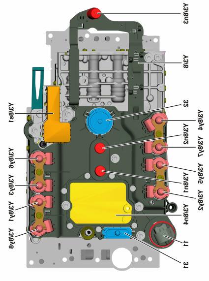
15
16 5. Can you reuse the valve body to transmission housing bolts? YES NO 6. What is the tightening torque of the valve body bolts? 7. Can you reuse the oil pan bolts? YES NO 8. What is the tightening torque of the oil pan bolts? Notes: 286 Mod Trans D&A (Todd,D) doc 16
Transaxle. 1. Mount the transaxle to Bench Mounted Holding Fixture T57L-500-B.
 «1997 Aspire Table of Contents» «Group 07: TRANSAXLE» «Section 07-01: Transaxle, Automatic» «DISASSEMBLY» Transaxle CAUTION: To prevent dirt from entering the transaxle, it should be disassembled and kept
ASSEMBLY PROCEDURE AUTOMATIC TRANSMISSION 5A-173. Transmission
 AUTOMATIC TRANSMISSION 5A-173 ASSEMBLY PROCEDURE Transmission Tools Required 0555-336256 Transmission Bench Cradle 0555-336258 Cross Shaft Pin Remover/Installer (Detent Lever) 0555-336262 Cross Shaft Seal
DRIVE AXLE Volvo 960 DESCRIPTION & OPERATION AXLE IDENTIFICATION DRIVE AXLES Volvo Differentials & Axle Shafts
 DRIVE AXLE 1994 Volvo 960 1994 DRIVE AXLES Volvo Differentials & Axle Shafts 960 DESCRIPTION & OPERATION All 960 station wagon models use type 1041 rear axle assembly. All 960 4-door models use type 1045
ASSEMBLY PROCEDURE. Transmission
 67 ASSEMBLY PROCEDURE Transmission Tools Required 0555-336256 Transmission Bench Cradle 0555-336258 Cross Shaft Pin Remover/Installer (Detent Lever) 0555-336262 Cross Shaft Seal Installer 0555-336263 Cross
Instructions to install the early ( ) Limited Slip Differential in the Late-model ( ) G28 Transaxle
 Limited Slip Differential in the Late-model ( ) G28 Transaxle") Instructions to install the early (1978-83) Limited Slip Differential in the Late-model (1985-1995) G28 Transaxle BACKGROUND: Most 928 owners know about the improvements to the 5- speed transaxle that
Instructions to install the early (1978-83) Limited Slip Differential in the Late-model (1985-1995) G28 Transaxle BACKGROUND: Most 928 owners know about the improvements to the 5- speed transaxle that
AR28.10-P-1004SYZ Disassemble, assemble and seal MODEL /18, /28 with TRANSMISSION 722.9
 AR28.10-P-1004SYZ Disassemble, assemble and seal 31.7.07 MODEL 221.08 /18, 204.08 /28 with TRANSMISSION 722.9 1 Collar nut 2 Output flange 3 Radial shaft seal 4 Intermediate housing 5 Automatic transmission
Dismantling and assembling transmission
 27-640 Dismantling and assembling transmission Operation number of the operation texts and work units or standard texts and flat rates: 27-4010 P27-5367-61 Control pressure cable (98) Slacken, remove and
Model 4360 Teardown and Reassembly Instructions
 Clean the outside surface of the transaxle. Place the shifter in neutral position. Remove detent cover screw (item 3), detent cover (item 4), detent springs (item 5), and detent balls (item 6). Use a magnet
Dismantling and assembling automatic transmission (A5S560Z) (transmission removed)
 (transmission removed)") 24 00 585 Dismantling and assembling automatic transmission (A5S560Z) (transmission removed) Secure transmission to assembly frame with special tool 24 0 180. Drain off transmission oil. Screw special
24 00 585 Dismantling and assembling automatic transmission (A5S560Z) (transmission removed) Secure transmission to assembly frame with special tool 24 0 180. Drain off transmission oil. Screw special
LB7/ LLY Allison 5 speed transmissions
 PPEdiesel.com STAGE 4 TRANSMISSION KIT INSTALLATION GUIDE 2001-2005 LB7/ LLY Allison 5 speed transmissions Technical Support (714) 985-4825 Rev: 01/31/18 v7 DISCLAIMER OF LIABILITY This is a performance
Description and Operation
 Description and Operation Clean the automatic transmission to prevent dirt entering when it is reassembled. Lay the removed parts out clearly to make it easier to assess damage and reassemble components.
REPAIR INSTRUCTIONS ON-VEHICLE SERVICE TRANSMISSION AUTOMATIC TRANSMISSION 5A-159. Removal and Installation Procedure
 REPAIR INSTRUCTIONS YAD5A080 AUTOMATIC TRANSMISSION 5A-159 ON-VEHICLE SERVICE TRANSMISSION Removal and Installation Procedure 1. Disconnect the negative battery cable. 2. Disconnect the connectors from
 Page 1 of 22 SECTION 307-01: Automatic Transaxle/Transmission 4R70E/4R75E ASSEMBLY Procedure revision date: 05/29/2009 Transmission Printable View (1554 KB) Special Tool(s) Air Test Plate, Transmission
2003 E-Series Workshop Manual
 Page 1 of 20 SECTION 307-01B: Automatic Transmission 4R70W 2003 E-Series Workshop Manual ASSEMBLY Procedure revision date: 04/27/2006 Transmission Printable View (1828 KB) Special Tool(s) Dial Indicator
Stage4 Installation Guide STAGE 4 TRANSMISSION KIT INSTALLATION GUIDE Allison LB7/ LLY only for 5 speed trasmissions
 STAGE 4 TRANSMISSION KIT INSTALLATION GUIDE 2001-2005 Allison LB7/ LLY only for 5 speed trasmissions DISCLAIMER OF LIABILITY This is a performance product which can be used with increased horsepower above
1967 (Late) CORVETTE STANDARD (NON-ADJUSTABLE) STEERING COLUMN DISASSEMBLY & REPAIR INSTRUCTIONS PAPER #2
 CORVETTE STANDARD (NON-ADJUSTABLE) STEERING COLUMN DISASSEMBLY & REPAIR INSTRUCTIONS PAPER #2") Last Revision: 03SE2012 1967 (Late) - 1968 CORVETTE STANDARD (NON-ADJUSTABLE) STEERING COLUMN DISASSEMBLY & REPAIR INSTRUCTIONS PAPER #2 Disassembly and Repair Instructions Addressed in this Paper Degree
Last Revision: 03SE2012 1967 (Late) - 1968 CORVETTE STANDARD (NON-ADJUSTABLE) STEERING COLUMN DISASSEMBLY & REPAIR INSTRUCTIONS PAPER #2 Disassembly and Repair Instructions Addressed in this Paper Degree
AUTOMATIC TRANSMISSIONS Mitsubishi F3A20 Series TRANSMISSION APPLICATION TABLE
 Article Text ARTICLE BEGINNING AUTOMATIC TRANSMISSIONS Mitsubishi F3A20 Series APPLICATION TRANSMISSION APPLICATION TABLE Vehicle Application Transmission Model Colt 3-Speed (1990-94)... F3A21 Colt Vista
Heavy Duty Miniature Quick-Change Applicator (Side-Feed Type) with Mechanical or Air Feed Systems
 with Mechanical or Air Feed Systems") Heavy Duty Miniature Quick-Change Applicator (Side-Feed Type) with Mechanical or Air Feed Systems Instruction Sheet 408-8040 30 NOV 17 Rev H Ram Assembly Ram Post Locking Screw Stock Drag Drag Release
Heavy Duty Miniature Quick-Change Applicator (Side-Feed Type) with Mechanical or Air Feed Systems Instruction Sheet 408-8040 30 NOV 17 Rev H Ram Assembly Ram Post Locking Screw Stock Drag Drag Release
ZF 6HP26 / 6HP28 6HP26 6HP28. Automatic Transmission Spare Parts Catalog
 ZF 6HP26 / 6HP28 6HP26 6HP28 Automatic Transmission Spare Parts Catalog Warranty Information Warranty coverage for ZF passenger car transmission spare parts and kits covers the first 12 months after installation
46RE, 46RH, 47RE, 47RH ZIP KIT
 46RE, 46RH, 47RE, 47RH ZIP KIT PART NUMBER 46-47RHE-ZIP QUICK GUIDE Parts are labeled here in order of installation. See other side of sheet for details on Zip Kit contents. installation Diagram 7 1 Separator
REPAIR MANUAL. Version 02/11/01 CD ZF GETRIEBE GMBH SAARBRÜCKEN
 REPAIR MANUAL 6 HP-26 Version CD ZF GETRIEBE GMBH SAARBRÜCKEN subject to alterations Copyright 2002 all rights reserved and published by ZF Getriebe GmbH, Saarbrücken, Department MKTD No part of this manual
DISASSEMBLY. Transmission. All vehicles
 307-01-1 Automatic Transmission 5R44E and 5R55E 307-01-1 DISASSEMBLY Transmission Special Tool(s) Holding Fixture, Transmission 307-262 (T93T-77002-AH) Special Tool(s) Remover, Servo 307-347 (T97T-7D021-A)
REPAIR MANUAL 5 HP - 30 ZF GETRIEBE GMBH SAARBRÜCKEN
 REPAIR MANUAL 5 HP - 30 ZF GETRIEBE GMBH SAARBRÜCKEN Impressum: Verantwortlich für den Inhalt Abteilung MKTD, ZF Getriebe GmbH, Saarbrücken Druck: HAGER PAPPRINT GmbH, Gedruckt in der BRD Published by
DISASSEMBLY AND ASSEMBLY
 307-01-1 Automatic Transaxle/Transmission 307-01-1 DISASSEMBLY AND ASSEMBLY Transaxle Special Tool(s) Dial Indicator Gauge With Holding Fixture 100-002 (TOOL-4201-C) Special Tool(s) Test Plate Screw Set,
GM 4L80-E, 4L85-E SURE CURE KIT
 GM 4L80-E, 4L85-E SURE CURE KIT PART NUMBER SC-4L80E INSTALLATION GUIDE Parts are labeled here in order of installation. See page 2 for details on Sure Cure kit contents. See Sure Cure instruction booklet
TCI Trans-Scat
 Page 1 of 5 Return to Instruction Sheet index TCI 400000 Trans-Scat Turbo Hydramatic 400-1965-Up This kit will allow you to re-program your transmission valve body. This kit will give you firm positive
ASSEMBLY. Transmission Automatic Transaxle/Transmission. Special Tool(s) Alignment Set, Fluid Pump 307-S039 (T74P X) Special Tool(s)
 Alignment Set, Fluid Pump 307-S039 (T74P X) Special Tool(s)") 307-01-1 Automatic Transaxle/Transmission 307-01-1 ASSEMBLY Transmission Special Tool(s) Adjustment Set, Transmission Band 307-S022 (T71P-77370-A) Special Tool(s) Alignment Set, Fluid Pump 307-S039 (T74P-77103-X)
307-01-1 Automatic Transaxle/Transmission 307-01-1 ASSEMBLY Transmission Special Tool(s) Adjustment Set, Transmission Band 307-S022 (T71P-77370-A) Special Tool(s) Alignment Set, Fluid Pump 307-S039 (T74P-77103-X)
Evora shiftr111 Installation Instructions Rev. B Page 1 of 14
 Evora shiftr111 Installation Rev. B Page 1 of 14 READ FITTING INSTRUCTIONS IN FULL BEFORE INSTALLATION This article is sold without warranty expressed or implied. No warranty or representation is made
DRIVE AXLE Nissan 240SX DESCRIPTION & OPERATION AXLE RATIO & IDENTIFICATION AXLE SHAFT & BEARING R & I DRIVE SHAFT R & I
 DRIVE AXLE 1990 Nissan 240SX 1990 DRIVE AXLES Rear Axle - R200 240SX, 300ZX DESCRIPTION & OPERATION The axle assembly is a hypoid type gear with integral carrier housing. The pinion bearing preload adjustment
HIGH PERFORMANCE TRANSMISSION PARTS Instructions. Line Pressure Booster Kit. TCC Control Plunger Valve Kit. Line Pressure Modulator Plunger Valve Kit
 Performance Pack Ford 4R100 Part No. HP-4R100-01 Line Pressure Booster Kit Line-to-Lube Pressure Regulator Valve Line Pressure Booster Kit Valve Sleeve O-Rings (2) TCC Control Plunger Valve Kit Front Lube/Drainback
GM 4L80-E, 4L85-E SURE CURE KIT
 GM 4L80-E, 4L85-E SURE CURE KIT PART NUMBER SC-4L80E INSTRUCTION BOOKLET Parts are labeled here in order of installation. See page 2 for details on Sure Cure kit contents. See Sure Cure instruction booklet
2000 Jeep Truck Cherokee 4WD L6-4.0L VIN S
 2000 Jeep Truck Cherokee 4WD L6-4.0L VIN S Vehicle» Transmission and Drivetrain» Automatic Transmission/Transaxle» Service and Repair» 30-40LE (AW4) 4 Speed» Overhaul (Transmission)» Disassembly DISASSEMBLY
HAKO cut-away models. 10: Clutches, Transmission, Automatic Transmission, Rear-wheel Drive, Front-wheel Drive, Steering, Chassis, Damping, Suspension
 10: Clutches, Transmission, Automatic Transmission, Rear-wheel Drive, Front-wheel Drive, Steering, Chassis, Damping, Suspension Order No. 1211 Clutch functional model A diaphragm spring clutch is mounted
2002 F-Super Duty /Excursion Workshop Manual
 Page 1 of 25 SECTION 307-01: Automatic Transaxle/Transmission 2002 F-Super Duty 250-550/Excursion Workshop Manual ASSEMBLY Procedure revision date: 05/23/2001 Transmission Special Tool(s) Remover, O-Ring
Figure 1: LCT 1000 mounted on a dyno for the purpose of this article.
 A Fast Fix for the Allison LCT 1000 A Fast Fix for the Allison LCT 1000 by David Skora Figure 1: LCT 1000 mounted on a dyno for the purpose of this article. Most Duramax trucks are bought to do work. Most
2001 F-150 Workshop Manual
 Page 1 of 7 Differential Case and Ring Gear Traction-Lok Special Tool(s) 2-Jaw Puller 205-D072 (D97L-4221-A) or equivalent Installer, Differential Carrier Bearing 205-D044 (D81T-4221-A) or equivalent 15-101
23. Planetary Gear and Low Clutch S510212
 Automatic Transmission 23. Planetary Gear and Low Clutch S510212 A: REMOVAL S510212A18 1) Extract the torque converter clutch assembly. 2) Remove
HIGH PERFORMANCE TRANSMISSION PARTS Instructions. Line Pressure Booster Kit. TCC Control Plunger Valve Kit. Line Pressure Modulator Plunger Valve Kit
 Performance Pack Ford 4R100 Part No. HP-4R100-01 Line Pressure Booster Kit Line-to-Lube Pressure Regulator Valve Line Pressure Booster Kit Valve Sleeve O-Rings (2) TCC Control Plunger Valve Kit Front Lube/Drainback
WORKSHEET 4-1 Transaxle Case Removal and Component Identification
 WORKSHEET 4-1 Transaxle Case Removal and Component Identification Vehicle: Year/Prod. Date: Engine Transmission: Worksheet Objectives With this worksheet, you will follow the disassembly of a front-drive
Assembly. NOTE: Before beginning assembly, perform/inspect the following:
 Page 1 of 31 Home Account Contact ALLDATA Log Out Help DAN GRIMWOOD DAN GRIMWOOD00002 Select Vehicle New TSBs Technician's Reference Component Search: OK 1997 Ford Truck F 150 2WD Pickup V6-4.2L VIN 2
Step 3: Remove the six 8mm retaining bolts for the pressure manifold switch assembly. The manifold switch will not be re-installed.
 1 INSTRUCTIONS TCI 274500/274501 4L80E Trans Brake Valve Body Thank you for choosing TCI products. We are proud to be your manufacturer of choice. Please read this instruction sheet carefully before beginning
1. General Description
 1. General Description A: SPECIFICATION 1. MANUAL TRANSMISSION AND FRONT DIFFERENTIAL Type Transmission gear ratio Front reduction gear Rear reduction gear Front differential Center differential Final
ZF 6HP19X / 6HP21X 6HP19X 6HP21X. Automatic Transmission Spare Parts Catalog
 ZF 6HP19X / 6HP21X 6HP19X 6HP21X Automatic Transmission Spare Parts Catalog Warranty Information Warranty coverage for ZF passenger car transmission spare parts and kits covers the first 12 months after
DC 5-SPEED AUTOMATIC TRANSMISSION
 03 1. OVERVIEW 2WD 4WD DCAG 5speed automatic transmission is an electronically controlled 5speed transmission with a lockup clutch in the torque converter. The ratios for the gears are realized by three
1989 Jeep Cherokee. STEERING COLUMN' '1989 STEERING Jeep Steering Columns STEERING COLUMN STEERING Jeep Steering Columns
 STEERING COLUMN 1989 STEERING Jeep Steering Columns DESCRIPTION All models use collapsible steering columns. All columns have integral ignition switch and locking device. Optional tilt wheel is available
NOTE: Clean and inspect all components. Replace any components which show evidence of excessive wear or scoring.
 21 - Transmission and Transfer Case/Automatic - 68RFE/Assembly ASSEMBLY Labor Operations: Click to display a list of Labor Operations associated with this procedure Special Tools: Click to display a list
AUTOMATIC TRANSMISSIONS ZF 4HP 18
 AUTO TRANS OVERHAUL - ZF 4HP 18 Article Text 1991 Eagle Premier For Dan's Transmission Service 10 Jefferson Place Fort Walton Beach FL 32548 1997 Mitchell Repair Information Company, All Rights Reserved.
2007 Dodge Nitro R/T
 ASSEMBLY AUTOMATIC TRANSMISSION - 42RLE NOTE: If the transmission assembly is being reconditioned (clutch/seal replacement) or replaced, it is necessary to perform the TCM QUICK LEARN Procedure using the
International DT 466, DT 570 and HT 570 Turbo Repair
 A NAVISTAR COMPANY International DT 466, DT 570 and HT 570 Turbo Repair Study Guide TMT-121008 Study Guide International DT 466, DT 570 and HT 570 Turbo Repair TMT-121008 2010 Navistar, Inc. 4201 Winfield
2005 Toyota RAV AUTOMATIC TRANSMISSIONS U240E & U241E Overhaul
 2001-05 AUTOMATIC TRANSMISSIONS U240E & U241E Overhaul APPLICATION CAUTION: Flush oil cooler and oil cooler lines prior to transaxle installation. Oil cooling system contamination may cause premature transaxle
Disassembly and Reassembly Manual
 AS No.ER2-0908-MC-00 ER2 Series Electric Chain Hoist (125kg to 5t) Disassembly and Reassembly Manual Safety precaution This Disassembly and Reassembly Manual includes contents to prevent injury to any
Shown on model Bolts 6 Oil lines 5 Screw 7 Adjusting screw Shown on model 209
 AR46.20-P-0003Q Replace bottom radial shaft sealing ring on control head 4.5.07 MODEL 203, 209 except CODE (213) Speed-sensitive power steering MODEL 215, 220 Shown on model 209 1 Clamps 2 Bellows 3 Inner
Heavy Duty Miniature Quick-Change Applicator (End-Feed Type) with Mechanical or Air-Feed Systems
 with Mechanical or Air-Feed Systems") Heavy Duty Miniature Quick-Change Applicator (End-Feed Type) with Mechanical or Air-Feed Systems Instruction Sheet 408-8039 02 JUN 16 Rev G Ram Post Wire Disc Insulation Disc Insulation Crimper Stripper
Heavy Duty Miniature Quick-Change Applicator (End-Feed Type) with Mechanical or Air-Feed Systems Instruction Sheet 408-8039 02 JUN 16 Rev G Ram Post Wire Disc Insulation Disc Insulation Crimper Stripper
Steering Gearbox Disassembly
 Steering Gearbox Disassembly Steering Rack Disassembly 5. Unbend the lock washer. Before disassembling the gearbox, wash it off with solvent and a brush. Do not dip seals and O-rings in solvent. 1. Remove
Geo Prizm ( LSi) Toyota Celica 1.8L (1994)
 Toyota Celica 1.8L (1994)") Page 1 of 140 ARTICLE BEGINNING APPLICATION TRANSMISSION APPLICATIONS Application Geo Prizm (1993-94 LSi) Toyota Celica 1.6L (1993) Celica 1.8L (1994) Celica 2.2L (1993) Corolla 1.8L MR2 Paseo Transaxle
Page 1 of 140 ARTICLE BEGINNING APPLICATION TRANSMISSION APPLICATIONS Application Geo Prizm (1993-94 LSi) Toyota Celica 1.6L (1993) Celica 1.8L (1994) Celica 2.2L (1993) Corolla 1.8L MR2 Paseo Transaxle
INSTALLATION INSTRUCTIONS 68RFE ZERO-TUNE.
 1 TORQUE SPECIFICATIONS 2 IMPORTANT: The RevMax ZeroTune kit requires the transmission to be removed from the vehicle and be partially disassembled. It is recommended that a professional transmission technician
ZF 6HP26A 61 6HP26A 61. Automatic Transmission Spare Parts Catalog
 ZF 6HP26A 61 6HP26A 61 Automatic Transmission Spare Parts Catalog Warranty Information Warranty coverage for ZF passenger car transmission spare parts and kits covers the first 12 months after installation
ZF 6HP26X / 6HP28X 6HP26X 6HP28X. Automatic Transmission Spare Parts Catalog
 ZF 6HP26X / 6HP28X 6HP26X 6HP28X Automatic Transmission Spare Parts Catalog Warranty Information Warranty coverage for ZF passenger car transmission spare parts and kits covers the first 12 months after
INSTALLATION GUIDE CRF150R Manual Revision:
 REKLUSE MOTOR SPORTS The z-start Pro Clutch INSTALLATION GUIDE CRF150R 191-810 Manual Revision: 032508 2002 Rekluse Motor Sports Rekluse Motor Sports, Inc. 110 E. 43rd Street Boise, Idaho 83714 208-426-0659
DRIVE AXLE - INTEGRAL HOUSING
 DRIVE AXLE - INTEGRAL HOUSING 1993 Toyota Celica 1993 DRIVE AXLES Toyota Differentials & Axle Shafts - Integral Housing Toyota; Celica All-Trac DESCRIPTION Drive axle assembly is a hypoid type with integral
MANUAL TRANS OVERHAUL - BORG-WARNER - T56 6-SPEED MANUAL TRANSMISSIONS Borg-Warner T56 (MM6) 6-Speed
 6-Speed") IDENTIFICATION MANUAL TRANS OVERHAUL - BORG-WARNER - T56 6-SPEED 1998 MANUAL TRANSMISSIONS Borg-Warner T56 (MM6) 6-Speed Transmission has 2 identification labels, located on lower left side of case. One
IDENTIFICATION MANUAL TRANS OVERHAUL - BORG-WARNER - T56 6-SPEED 1998 MANUAL TRANSMISSIONS Borg-Warner T56 (MM6) 6-Speed Transmission has 2 identification labels, located on lower left side of case. One
ASSEMBLY. Transmission Automatic Transmission 5R44E and 5R55E. Special Tool(s)
") 307-01-1 Automatic Transmission 5R44E and 5R55E 307-01-1 ASSEMBLY Transmission Special Tool(s) Holding Fixture, Transmission 307-262 (T93T-77002-AH) Special Tool(s) Installer, Transmission Extension Housing
307-01-1 Automatic Transmission 5R44E and 5R55E 307-01-1 ASSEMBLY Transmission Special Tool(s) Holding Fixture, Transmission 307-262 (T93T-77002-AH) Special Tool(s) Installer, Transmission Extension Housing
BRAKE SYSTEM Return To Main Table of Contents
 BRAKE SYSTEM Return To Main Table of Contents GENERAL... 2 BRAKE PEDAL... 10 MASTER CYLINDER... 13 BRAKE BOOSTER... 16 BRAKE LINE... 18 PROPORTIONING VALVE... 19 FRONT DISC BRAKE... 20 REAR DRUM BRAKE...
SECTION 3A FRONT DRIVE AXLE TABLE OF CONTENTS SPECIFICATIONS GENERAL SPECIFICATIONS. Description Drive Shaft Type. CV Joint Axle Housing Type
 SECTION 3A FRONT DRIVE AXLE TABLE OF CONTENTS Specifications........................ 3A-1 General Specifications.................. 3A-1 Fastener Tightening Specifications......... 3A-2 Component Locator...................
Fichtel and Sachs Old Torpedo Duomatic Re-assembly
 Fichtel and Sachs Old Torpedo Duomatic Re-assembly Inspection and assessment Refer to the final photograph in the dismantling instructions to see how all the parts should look cleaned up. This hub came
VAG-ID.RU Ремонт АКПП ZF 5HP19. Automatic Transmission Spare Parts Catalog
 ZF 5HP19 Automatic Transmission Spare Parts Catalog Warranty Information Warranty coverage for ZF passenger car transmission spare parts and kits covers the first 12 months after installation in the vehicle,
INSTALLATION GUIDE. Clutch Cable Actuated Models Manual Revision:
 REKLUSE MOTOR SPORTS The z-start Pro Clutch INSTALLATION GUIDE Clutch Cable Actuated Models 191-800 Manual Revision: 041513 2012 Rekluse Motor Sports Rekluse Motor Sports, Inc. 12000 W Franklin Rd. Boise,
AUTO TRANS OVERHAUL - V.A.G. 01V Article Text 1998 Volkswagen Passat This file passed thru Volkswagen Technical Site -
 AUTO TRANS OVERHAUL - V.A.G. 01V Article Text 1998 Volkswagen Passat This file passed thru Volkswagen Technical Site - http://volkswagen.msk.ru ARTICLE BEGINNING 1997-98 AUTOMATIC TRANSMISSIONS Volkswagen/Audi
SECTION 3D REAR AXLE TABLE OF CONTENTS
 SECTION 3D REAR AXLE TABLE OF CONTENTS General Description and Operation... 3D-2 Specifications... 3D-2 Fastener Tightening Specifications... 3D-2 Diagnostic Information and Procedures... 3D-3 Component
Amarillo PUMP DRIVES (250 HP THROUGH 350 HP) INSTRUCTIONS FOR REPAIRING MODELS 250, 300, and 350
 INSTRUCTIONS FOR REPAIRING MODELS 250, 300, and 350") Amarillo PUMP DRIVES (250 HP THROUGH 350 HP) INSTRUCTIONS FOR REPAIRING MODELS 250, 300, and 350 Amarillo Right Angle Pump Drives, if properly installed and maintained, should provide years of service
Amarillo PUMP DRIVES (250 HP THROUGH 350 HP) INSTRUCTIONS FOR REPAIRING MODELS 250, 300, and 350 Amarillo Right Angle Pump Drives, if properly installed and maintained, should provide years of service
AUTOMATIC TRANSMISSIONS. General Motors Corp. Hydra-Matic 4L60-E Overhaul
 1997-98 AUTOMATIC TRANSMISSIONS General Motors Corp. Hydra-Matic 4L60-E Overhaul APPLICATION TRANSMISSION APPLICATIONS Application Corvette Transaxle 4L60-E IDENTIFICATION The 4L60-E transmission can be
Turn cylinder CD by 180. Pull 2 O-ring seals and onto piston C and press it into the cylinder.
 Turn cylinder CD by 180. Pull 2 O-ring seals 75.040 and 75.050 onto piston C 75.030 and press it into the cylinder. 01276 Insert cup spring C 75.070 and retaining ring 75.080. Press down cup spring C in
PROPELLER SHAFT & DIFFERENTIAL CARRIER SECTIONPD CONTENTS
 PROPELLER SHAFT & DIFFERENTIAL CARRIER SECTIONPD CONTENTS PREPARATION...2 PROPELLER SHAFT...5 On-Vehicle Service...6 Removal and Installation...7 Inspection...7 Disassembly...7 Assembly...8 ON-VEHICLE
Technical Information Review
 Technical Information Review While every attempt is made to ensure that the technical information we supply is as accurate and up to date as possible, from time to time, errors do occur. There may also
Pull out clutch E snap ring and withdraw complete clutch pack of clutch E. 6 HP 26 ZF Getriebe GmbH Saarbrücken CD
 Press down cup spring in the mandrel press with assembly bracket 5x46 002 566 and remove snap ring with suitable pliers. Take out planet carrier and cup spring. Take the O-ring seal off the planet carrier.
Vehicle: Year/Prod. Date: Engine Transmission:
 WORKSHEET 4-2 Transaxle Shaft Removal and Inspection Vehicle: Year/Prod. Date: Engine Transmission: Worksheet Objectives With this worksheet, you will follow the disassembly of a front-drive transmission
INSTALLATION INSTRUCTIONS ASSEMBLY & DISASSEMBLY
 8405/6ASERIES PTO INSTALLATION INSTRUCTIONS ASSEMBLY & DISASSEMBLY 8405/6A DISASSEMBLY-REASSEMBLY INSTRUCTIONS This document contains the information to properly disassemble/reassembleyour 8405/6A Series
SUSPENSION - REAR Toyota Celica DESCRIPTION ADJUSTMENTS & INSPECTION WHEEL ALIGNMENT SPECIFICATIONS & PROCEDURES WHEEL BEARING
 SUSPENSION - REAR 1988 Toyota Celica REAR SUSPENSION Toyota IRS DESCRIPTION The Toyota Independent Rear Suspension (IRS) system utilizes MacPherson struts, which fasten to axle carrier and wheel housing.
Repair Manual VW 02J gearbox. INA GearBOX
 Repair Manual VW 02J gearbox INA GearBOX Special tools Pipe section, 50 mm: Press fitting of synchronizer body for third/fourth gear. Assembly of support bearing for input and output shaft. Part number:
1999 F-150/250 Workshop Manual
 Page 1 of 30 SECTION 205-03: Front Drive Axle/Differential Ford 8.8-Inch Ring Gear 1999 F-150/250 Workshop Manual DISASSEMBLY AND ASSEMBLY Procedure revision date: 01/08/2003 Axle Front Drive Special Tool(s)
1. Set the position of the hub to FREE and remove the six hex-drive bolts.
 1. Raise vehicle on a hoist, remove road wheels, disconnect the drag-link from the passenger-side hub assembly and disconnect the steering tie rod ends from both the driver and passenger side hub assemblies.
DISASSEMBLY TRANSAXLE DISASSEMBLY AND ASSEMBLY. Part 1 Of 3
 2004 Mitsubishi Truck Endeavor V6-3.8L SOHC Vehicle > Transmission and Drivetrain > Automatic Transmission/Transaxle > Service and Repair > Overhaul > F4A5A > Disassembly and Assembly DISASSEMBLY TRANSAXLE
INSTALLATION GUIDE. Clutch Cable Actuated Models Manual Revision:
 REKLUSE MOTOR SPORTS The z-start Pro Clutch INSTALLATION GUIDE Clutch Cable Actuated Models 191-800 Manual Revision: 061810 2002 Rekluse Motor Sports Rekluse Motor Sports, Inc. 110 E. 43rd Street Boise,
AUTOMATIC TRANSAXLE AUTOMATIC TRANSAXLE SYSTEM... COMPONENT PARTS...
 SYSTEM....... COMPONENT PARTS.................... OIL PUMP.............................. DIRECT CLUTCH........................ FORWARD CLUTCH..................... SECOND BRAKE........................ UNDERDRIVE
Chrysler 46RE, 46RH, 47RE, 47RH SURE CURE KIT
 Chrysler 46RE, 46RH, 47RE, 47RH SURE CURE KIT PART NUMBER SC-46-47RHE-OS INSTALLATION GUIDE Parts are labeled here in order of installation. See other side of sheet for details on Sure Cure kit contents.
York J Model Compressors Unloading Characteristics Styles A-F Solenoid Valve
 Styles A-F Solenoid Valve Loaded - De-energized Crankcase Access Cover Oil Pressure Supply Oil Supply Valve Spring, Washer/Keeper Valve Rod and Disk To Unloading Cylinder Plunger Plunger Disk Crankcase
ABBREVIATIONS USED IN THIS
 IN10 INTRODUCTION ABBREVIATIONS USED IN THIS MANUAL ABBREVIATIONS USED IN THIS MANUAL ATF Automatic Transmission Fluid B 0 Overdrive Brake B 2 Second Brake B 3 No. 3 Brake C 0 Overdrive Direct Clutch C
PAH, PAHT, PAHT G pumps PAH , PAHT and PAHT G Disassembling and assembling
 Servie guide PAH, PAHT, PAHT G pumps PAH 10-12.5, PAHT 10-12.5 and PAHT G 10-12.5 Disassembling and assembling hpp.danfoss.com Table of Contents 1. Disassembling the pump...3 2. Inspection...7 2.1. Port
Models & Inch & 4 Inch Digital Inline Pressure Control Valves SM64504
 SM64504 September 2008 Aerospace Group Conveyance Systems Division Carter Brand Ground Fueling Equipment Applicable addition manuals: None Maintenance & Repair Manual 3 Inch & 4 Inch Digital Inline Pressure
AJV8 Engine Assembly. AJV8 Engine Assembly
 AJV8 Engine Assembly Contents Cylinder Block Dowels, Plugs and Pipes 2 4 Crankshaft Bearing and Cylinder Bore Dimensions 5 9 Bearing Measuring 6 Engine Dimensions and Codes 6 7 Main Bearing Selection Chart
2001 Chevrolet Corvette AUTOMATIC TRANSMISSIONS Hydra-Matic 4L60-E - Overhaul
 2001-03 AUTOMATIC TRANSMISSIONS Hydra-Matic 4L60-E - Overhaul APPLICATION CAUTION: Flush oil cooler and oil cooler lines prior to transmission installation. Oil cooling system contamination may cause premature
2007 Jeep Truck Liberty 4WD V6 3.7L VIN K
 2007 Jeep Truck Liberty 4WD V6 3.7L VIN K Vehicle» Transmission and Drivetrain» Automatic Transmission/Transaxle» Service and Repair» Overhaul» Assembly ASSEMBLY NOTE: If the transmission assembly is being
X-Trainer 43mm fork service manual. Beta USA, Inc This work should be performed by a trained motorcycle technician.
 X-Trainer 43mm fork service manual Beta USA, Inc. 2016 This work should be performed by a trained motorcycle technician. Table of contents Page Introduction/special tools... 2 Fork exploded view... 3 Legend.
Repair Manual Ford DPS6 Gearbox. INA GearBOX
 Repair Manual Ford DPS6 Gearbox INA GearBOX Special Tools Tool kit (400 0477 10) for professional repair of the Ford DPS6 gearbox. Assembly table: Table (A) for securing the shafts, gear shift positions
Maintenance Information
 16572679 Edition 2 May 2014 Air Drill QP Series Maintenance Information Save These Instructions Product Safety Information WARNING Failure to observe the following warnings, and to avoid these potentially
2007 Jeep Truck Liberty 4WD V6 3.7L VIN K
 2007 Jeep Truck Liberty 4WD V6 3.7L VIN K Vehicle» Transmission and Drivetrain» Automatic Transmission/Transaxle» Service and Repair» Overhaul» Disassembly DISASSEMBLY NOTE: If the transmission is being
Flow Line Controls. Installation & Operations Manual SERIES 20/21 Pneumatic Actuators
 Flow Line Controls Installation & Operations Manual SERIES 20/21 Pneumatic Actuators Flow Line Controls, Inc. P.O. Box 677 Schriever, LA 70395 Phone: 985-414-6003 Toll Free 1-800-815-9226 Fax 985-414-6072
Advanced Auto Tech Worksheet Auto Trans & Transaxle Chapter 40 Pages Points Due Date
 Advanced Auto Tech Worksheet Name Auto Trans & Transaxle Chapter 40 Pages 1173 1215 107 Points Due Date 1. Automatic transmissions are operated by hydraulics as well as electronics to select according
SERVICE MANUAL 375 SERIES DIGGER MODELS
 SERVICE MANUAL 75 SERIES DIGGER MODELS Example Part Number 75 F 0 BP Model Ratio Shaft Bail Boss Motor Supplier Motor Number Back Spin Protection THIS SERVICE MANUAL IS EFFECTIVE: S/N: 00 TO CURRENT DATE:
Rear End Installation and Bearing Kit - 8.8in (86-12 V8; V6)
") Rear End Installation and Bearing Kit - 8.8in (86-12 V8; 11-13 V6) Tools Required: Jack Stands 5 Floor Jack 2 Oil Pans 1 Wheel Blocks 2 Differential Oil 3 qts Friction Modifier 3 bottles Tube of Black
Rear End Installation and Bearing Kit - 8.8in (86-12 V8; 11-13 V6) Tools Required: Jack Stands 5 Floor Jack 2 Oil Pans 1 Wheel Blocks 2 Differential Oil 3 qts Friction Modifier 3 bottles Tube of Black