Theimer Printing Light Assemblies VIOLUX 4002T VIOLUX 6002T VIOLUX 8002T. Instruction Manual
|
|
|
- Gerald Mills
- 6 years ago
- Views:
Transcription

1 Theimer Printing Light Assemblies VIOLUX 4002T VIOLUX 6002T VIOLUX 8002T Instruction Manual
2 Warning! Ultra-Violet Emission THEIMER lamps emit ultra-violet energy as well as carbon arcs, mercury vapor and similar light sources used in printing applications. The safety glass, which is furnished with all THEIMER VIOLUX lamp housing, provides protection for the operator by filtering out all UV B, wave lengths below 320 nm. Theimer Violux lighting systems use a DIN (DIN 1249) certified safety glass which meets the stringent European safety standards. Some Theimer self contained exposure systems are not equipped with the safety glass but incorporate electrical safety interlocks. These interlocks should not be defeated under any circumstance. In all Theimer exposing machines UV A is present in the exposure area, as with similar light sources used in printing applications. Operators must be instructed not to look directly into the light source or stare at reflected light from the light source. They are not to work or stand in front of the light source while it is exposing. UV protective curtains should be used to limit the exposure to the operator and to prevent other sensitive materials in the work area from being fogged. UNDER NO CIRCUMSTANCE should the THEIMER lighting system be operated without the ORIGINAL SAFETY GLASS in place or SAFETY INTERLOCKS DEFEATED. Should the safety glass break, it should be replaced only with a Theimer replacement glass. CAUTION Service All servicing of Theimer lighting systems should be performed by an approved technician or competent electrician. Several terminals within the lighting system carry high voltages and the unfiltered lamp produces high doses of UV A, B & C. When servicing, care must be taken to protect the service agent from the UV light generated by the lamp. 2
3 Contents Ultraviolet Emission...2 Service Warning...2 Description of the Violux...4 Technical Specification...4 Dimensions & Weight...4 Unpacking, Inspection, Installation...5 Lamp Installation...6 Ultraviolet Emission...7 Safety Glass...7 Mounting, overhead...7 Light Coverage...8 Electrical Connections...9 Line Cord Installation...9 Light integrator and RCB connection...10 Transformer TAP Adjustment...11 Operation...12 Turning the Unit ON...12 Theimotrol II...12 Exposure Control...13 Turning the Unit OFF...13 Exposure Times, factor affecting...14 Glass used on vacuum frames...14 Maintenance...15 Main Transformer Check...20 Shutter motor circuit...21 Blower control circuit...22 Lamp Ballast...23 Lamp starting circuit...24 Schematic of the the VT system...25 Trouble Shooting Guide...26 Power supply and lamp housing, picture...28 Parts list, power supply...29 Parts list, light unit...30 Parts list, RCB
4 DESCRIPTION The VIOLUX 4002T, 6002T and 8002T Printing Light Systems feature metal halide lamps whose spectral output matches the sensitivity of daylight films, sensitized plates and proofing materials. They utilize a metal shutter to obtain short exposures by eliminating warm-up times and spectral shifts that are normally associated with mercury vapor and "instant start" light sources. The VIOLUX operates in a stand-by condition with the shutter closed until an exposure is to be made. The shutter is opened by a light integrator or timer for the duration of the exposure. After the exposure is completed and the shutter closes, the lamp remains lit so that it is immediately ready for the next exposure. Optional Theimotrol II and Timetronic Light Integrators monitor the light intensity to maintain exposure accuracy. Using the Power level push buttons on the Theimotroll II or the remote control box, the operator can select the appropriate power level for their photographic materials. VIOLUX Printing Light Systems are designed for mounting over a horizontal printing frame. A printing lamp stand is available for use with vertical frames. The installation and operation of the VIOLUX 4002T, 6002T and 8002T are identical and all units are covered in this manual. Before unpacking and installing the equipment, it is suggested that this instruction manual be read carefully. Specifications Electrical Specifications VT 4 VT 6 VT 8 Line Voltage VAC VAC VAC Line Current 30 A 40 A 50 A External Control (through RCB) 115 VAC* 115 VAC* 115 VAC* Air Conditioning Load on High (BTU) Air Conditioning Load on Medium (BTU) Air Conditioning Load on Low (BTU) * 240 VAC & 24VDC optional Physical Specifications Width Depth Height Weight Power Supply 10.75" 25" 10.75" 150 lbs Light unit - with hood 22.5" 15.5" 32.5" 60 lbs Light unit - without hood 15.5" 15.5" 24" 50 lbs Remote Control Box (RCB) 6" 3.25" 2" 5 lbs Timetronic Integrator 7" 6.75" 4.75" 7 lbs Theimotrol II (ICS) 11.5" 6.75" 2.5" 7 lbs 4
5 INSTALLATION The VIOLUX 4002T, 6002T and 8002T Printing Lights are shipped in two cartons; one containing the power supply and the other the lamp housing and accessories, such as the integrator or control box. Printing stand or filters are packed separately. All equipment is thoroughly inspected., tested and carefully packed before leaving our warehouse. Responsibility for safe delivery is assumed by the carrier upon acceptance of the shipment. Any claim for damage or loss must be made by the consignee to the carrier. Should you notice any shipping damage contact your dealer and the carrier immediately. Claim for Damage or Loss VISIBLE DAMAGE OR LOSS: Any external evidence of damage or loss must be noted on the freight bill or express receipt and signed by the carrier's agent. The form required to file a claim will be supplied by the carrier. Failure to adequately describe external evidence of damage may result in the carrier refusing to honor damage claim. CONCEALED DAMAGE OR LOSS: Damage or loss may not be apparent until the merchandise has been unpacked. The equipment should be unpacked immediately and inspected for concealed damage. If concealed damage or loss is discovered, make a written request for inspection by carrier's agent within- 15 days of delivery date. Then file a claim with the carrier since such damage is the carrier's responsibility. In the event of damage or loss, SAVE ALL PACKING MATERIAL. When unpacking the equipment, do not discard any shipping cartons until the equipment is completely installed and operating properly. When removing the lamp housing from its shipping carton, DO NOT LIFT THE LAMP HOUSING BY THE MOTOR located on top of the unit. Inspection of Power Supply and Lamp Housing Prior to installation of the lamp housing and power supply, both units should be checked for loose hardware and electrical connections. Inspecting the equipment will assure greater operating reliability over it's life span. 5

6 Lamp Installation The lamp is supplied separately and must be mounted in the lamp housing. Lamps are installed from the front of the housing prior to installing the safety glass. The VIOLUX Tri-Level Printing Lights use the following lamp types: Lamp Type / Lighting System VT 4 VT 6 VT 8 Multi Spectrum THS 3027 THS 6027 THS 8027 Diazo THS 3020 THS 6020 n/a Power Bulb n/a THS 6029 n/a Note: 1. Use of lamps not manufactured by Theimer will void all warranties. 2. To install or replace the lamp, the equipment must be unplugged from the wall receptacle.! CAUTION Do not touch the glass envelope of the lamp with bare hands. Handle the lamps! only by the ceramic ends or use lint free gloves. Lamps should be thoroughly cleaned with the Theimer cleaning cloth supplied to remove any fingerprints, grease or other! contaminants on the glass.! The equipment is supplied with a special lamp socket to mount the lamp in a fixed position for optimum performance. It is important that only genuine Theimer lamps with THS designation be used in this equipment. These lamps have flat mounting ends which will match the socket. Older style TH designated lamps (having round ends) will not fit in the lamp mounting socket, however, THS lamps can be installed in the earlier Violux equipment.to install the lamp, place the flat ceramic ends of the lamp into their mounting clips, making sure that the flat ends are tightly held. Plug the wire leads securely into their quick-connect terminals on the ceramic insulators. Loose connections can cause overheating of the lamp, lamp wires or terminals, resulting in reduced lamp life. Make sure that the lamp wires do not touch any of the metal parts in the lamp housing. When replacing a lamp, check the quick-connect terminals for signs of arcing or corrosion. If they are dirty, replace them with new terminal lugs which are supplied with each replacement lamp. THS bulb 6
7 Ultra-Violet Emission VIOLUX lamps emit ultra-violet energy as well as carbon arcs, mercury vapor and similar light sources used in printing applications. The safety glass, which is furnished with all VIOLUX lamp housing, provides protection for the operator by filtering out all UV B, wave lengths below 320 nm. Theimer lighting systems use a DIN (DIN 1249) certified safety glass which meets the stringent European safety standards. However, UV A is emitted as with similar light sources used in printing applications. Operators must be instructed not to look directly into the light source, or stare at reflected light from the light source, and not to work or stand in front of the light source while it is exposing. UV protective curtains should be used to limit the exposure to the operator and to prevent other sensitive materials in the work area from being fogged. Under no circumstance should the VIOLUX be operated without the safety glass in place. Safety Glass The safety glass mounts in the tracks at the bottom of the lamp housing. It can be installed by sliding it into the tracks at both sides of the lamp housing. Before installing the safety glass, it should be thoroughly cleaned to prevent exposure times from being unnecessarily increased. After the safety glass is in place, the two air deflector brackets should be installed over the ends of the tracks to secure the safety glass. The screws for the air deflectors are supplied with the lamp housing. It is recommended that the safety glass, blower motor intake and reflectors be cleaned whenever the lamp is replaced. A dirty safety glass may increase exposure times by more than 50%. Note: Should the safety glass break, it should be replaced only with a Original Theimer replacement glass. Overhead Mounting Equipment designed for overhead mounting is provided with mounting brackets and cable fittings. The lamp housing can be mounted with wire cables or chains attached to the ceiling, or by overhead mounting assemblies furnished by the vacuum frame manufacturer to fit the VIOLUX. When mounting the lamp housing over a vacuum frame, it is important that the normal air flow to the lamp housing is not restricted. A minimum of 6" is required between the blower and ceiling for proper air circulation. Locating the lamp housing within a dropped ceiling should be avoided to prevent hot air normally trapped above the ceiling from recirculating back into the lamp housing. If it is necessary to mount the lamp housing higher than the level of a dropped ceiling, it is recommended that the opening in the ceiling above the lamp housing be at least 12" wider than the lamp housing on all sides. This will allow the air drawn into the housing to come from the printing area. 7

8 Light Coverage Proper coverage is determined by the distance between the lamp housing and vacuum frame, centering the lamp housing both horizontally and vertically and the position of the lamp in its holder. Even coverage can be obtained for various size materials, according to the following table. Frame Size or Material Format Minimum Light to Frame Distance 30" x 40" 34" 37" x 45" 41" 42" x 52" 48" 48" x 60" 56" 60" x 80" 77" For better collimation of light in film applications, it is recommended that the distance from the safety glass to the vacuum frame glass be a minimum of 40", for a 30" x 40" vacuum frame. This distance should be used especially if exposures are to be made through the base of the film. The distance between the light source and the frame also determines the exposure times. For the shortest exposures, the lamp housing should be placed as close as possible to the vacuum frame where even coverage is still obtained. Exposure tests should be made to determine the proper coverage and exposure times. These factors are effected by the materials, the frame size and other variables. 8
9 Electrical Connections Power supplies for the VIOLUX 4002T, 6002T and 8002T are designed to operate from 200 to 250 volts, single phase, 60 Hz. Line Cord & Plug Installation In order to add greater flexibility to the product, Lamp Express has included a NEMA 6-30/50 Plug and 8 ft. of Power Cord Cable. This will give your electrician the option of using your Plant standards, hard wiring the lighting system, or the using the NEMA 6-30/50 Plug with the 8 ft line cord. Please note, even though we supply 8 ft of line cord It should be cut to the length that is required for your installation. It is a good practice to keep power cable runs as short as possible. 1. Strip back 2 1 /4 " of the outer jacket from both ends of the Power Cable. 2. Strip back 5/8" of the insulation from each of the Black and the White wires. 3. Strip back 9/16" of the insulation from Green wire. 4. VT 4 units only! Install the NEMA 6-30/50 Plug in the 30 Amp configuration. Connect the black wire to a large flat blade. 4. VT 6 and VT 8 units only! Install the NEMA 6-30/50 Plug in the 50 Amp configuration. Connect the black wire to the small flat blade All units 5. Connect the white wire to the large flat blade. 6. Connect the green wire to the round blade. 7. Remove the strain relief from the plug body and insert the plug blades into the vertical openings in the plug body. 8. Reinstall the strain relief and make sure that the blades are seated properly. 9. Make sure that there are no strands of wire out of place. 10. Install the cover and tighten the four cover screws. 11. Tighten the strain relief. 12. Remove the power supply cover. 13. Feed the cable through the strain relief. 14. Connect the white wire to the main power switch (Q1) L1 terminal. con t 9

10 Line Cord & Plug Installation, con t. 15. Connect the black wire to the main power switch (Q1) L2 terminal. 16. Connect the green wire to the ground terminal on the main power switch (Q1). 17. Check the security of all electrical connections and mechanical fasteners. 18. Do not reinstall the power supply cover. (Follow transformer TAP adjustment instructions first) VT Power Supply Switch, Fan, Cable & Interface Connections The light unit is connected to the rear of the power supply with a quick disconnect plug. Insert the plug into the socket and set the retaining latches. Remote Control Box Connection A Remote Control Box (RCB) is supplied. This box includes switches for turning on the VIOLUX and selecting the power levels. The Remote Control Box also provides the interface for integrators utilizing 115 volts control outputs, such as our Timetronic line. The Remote Control Box (RCB) is connected to the power supply with a 25 pin DIP interface plug. Insert the interface plug into the socket at the rear of the power supply and tighten the locking screws. 10

11 Transformer Tap Adjustment The incoming TAP wire has not been installed on the main transformer. The wire is marked TAP and is in front of the incoming TAP terminals on the main transformer with a heat shrink boot over it. Prior to installation all the electrical connections should be checked for security and the incoming tap wire has to be set to the proper terminal on the main transformer. Remove the top cover from the power supply and tighten all electrical connections. Make sure that the main disconnect is set to the OFF position. Plug the power supply into a properly rated wall outlet. Measure the incoming line voltage at the main disconnect. Unplug the power supply from the wall outlet and set the incoming TAP wire to the proper voltage terminal on the main transformer. The equipment may be operated with line voltage below 200 volts without damage to the equipment. However to achieve maximum performance the line voltage should be raised to at least 200 volts. This can be achieved by purchasing a buck boost transformer from a local electrical suppliers. Incoming Voltage (Volts) TAP Position (200 V) (220 V) (240 V) TAP wire con t. from page After the tap is set turn off the unit and unplug the power supply from the wall outlet. 20. Now reinstall the power supply cover. 11

12 OPERATION Turning On The Equipment The VIOLUX Tri-Level can be left in a ready position by turning on the power disconnect switch located at the rear of the Power Supply. Depress the ON push button on the Power Supply or the Remote Control Box to turn the system on. The lamp will ignite and gradually increase in intensity as it warms up. During the initial warm up period, the blower in the lamp housing will not operate. As soon as the lamp reaches its proper operating temperature, an electronic sensor in the VIOLUX will activate the blower motor for proper cooling. This will normally require approximately 90 seconds. Remote Control Box (RCB) Power Control The VIOLUX Tri-Level has three power levels of operation. These power levels are controlled by a selector switch on the Remote Control Box. The desired power level is automatically switched when an exposure is made. 12
13 Exposure Control Exposure times can vary due to line voltage fluctuation, lamp aging or a dirty safety glass. For this reason the use of a light integrator is recommended to maintain precise repeatable exposure control. For the most accurate control, the photocell should be located on the vacuum frame. The photocell should never be located in the lamp housing behind the safety glass. For details on calibrating the light source to the integrator and other features, refer to the instruction manual of the integrator being used. Turning Off The Equipment The VIOLUX may be turned off if it is not going to be used to make an exposure within the next hour. If it is anticipated that an exposure will have to be made in less than an hour, it is more economical to leave the equipment on. Note: Each time the equipment is turned on, the re-ignition of the lamp may shorten the lamp life. The electrical cost for one hour of standby operation is minimal. To turn the system off, depress either the OFF push button on the Power Supply or the Remote Control Box. When the VIOLUX Tri-Level Lighting System is turned off by the OFF push button, the blower will run at high speed for about 120 seconds. Turning the unit off by the main disconnect will defeat the post cooling feature. If the VIOLUX is turned on before the lamp has sufficiently cooled down, the lamp may not ignite. The blower in the lamp housing will automatically start cooling the lamp until re-ignition temperature is obtained. The blower will then stop and remain off until the lamp reaches its proper standby temperature. For best results in reigniting the lamp, it is recommended that the equipment not be started until the post cooling fan has turned itself off. 13
14 Factors Affecting Exposure Times The VIOLUX Tri-Level Printing Lights are designed to expose various materials, printing plates, color proofing materials, screen printing resists, daylight films, etc. Some of the factors that can affect the exposure times on these materials are: Cleanliness A dirty safety glass can often cause a significant increase in exposure time. Type of glass used on vacuum frame: Older glass or glass that has been cleaned with polymer cleaners tends to pass less actinic energy and could increase exposure times. Acetate overlay sheets will lengthen exposure times. Some manufacturers film bases are less transparent to UV energy than others and could cause longer exposure times. Lamp Overheating or over cooling of the lamp can also increase exposure times. Exposure times for the VIOLUX Tri-Level Printing Lights should remain relatively constant during the life of the lamp. A gradual decrease in actinic output due to blackening of the quartz is a typical characteristic of all high intensity arc lamps. VIOLUX multi spectrum lamps, because of their smaller electrodes and improved halogen cycle, produce less blackening than similar metal halide lamps made by other manufacturers and retain their actinic output for longer periods of time. For this reason, it is strongly recommended that only genuine Theimer THS lamps be used in the equipment. These lamps are warranted to retain 80% of their actinic energy, measured at 365 nm, during the first 1000 hours of operation. Other lamps typically lose 50% of their actinic energy after only 500 hours of operation. 14
15 MAINTENANCE Electrical Operation Trouble-shooting the operation and functions of various components are described below. Simplified schematics of the important circuits are shown for your convenience. For more details, please refer to the schematics at the end of this section. Fuses Index Rating, Amps Description F1 4 Main power control circuit and post cooling F2 2 Control and light unit blower F3 & F4 4 Shutter and DC control circuits F5 1 Power Supply cooling fan CAUTION All servicing of the VIOLUX Lamp Housing or Power Supply should only be performed by an approved technician or competent electrician. Several terminals within the lighting system carry high voltages. 15
16 Relays and Contactors K1 - Main Power Contactor Actuates when the ON push button is depressed. Contacts apply incoming power to the equipment. A set of latching contacts bridge the ON push button to maintain power. K2 - Post Cooling Timer Actuated when the OFF push button is depressed. Provides power to the cooling system to accelerate cool down of the lamp which allows for quick re-ignition. The time interval is set for 120 seconds and is adjustable by the thumb wheel on top of the contactor. K3 - Expose Relay Actuated when the integrator is operated to make an exposure. Two sets of contacts switch DC voltage to shutter motor from Minus (-) to Plus (+) to open the shutter. The auxiliary timer delays the return to medium power when making exposures in power Level I & III. The timer is set for approximately one second and is adjustable by a conveniently located dial. K4 - Low Power Contactor Actuated whenever exposures are made in low power. N.O. contacts select the full winding of the reduced power inductor, L-1. It also selects the low speed cooling capacitor. When the contactor is relaxed, the N.C. contacts select half of the reduced power inductor and the medium speed cooling capacitor. K5 - High Power Contactor Actuated whenever exposures are made in Power Level III. Contacts bypass the reduced power inductor for high power operation. A second set of contacts bypasses standby blower capacitors for high speed operation of blower motor. K9 - Remote Off Relay This is located on the A5 printed circuit board. When the remote OFF push button is depressed and the K9 energized, the normally closed points interrupt power to the K1, main power contactor. The normally open contacts apply power to the K2, post cooling relay. K10 - Remote Exposure Control-Relay This provides a 110 volt interface for the power supply shutter control circuit. The coil is connected to the integrator input connector on the remote box. The points apply power to the K3 contactor in the power supply. 16
17 Capacitors C1 - Line Compensation Capacitors Balances the heavy inductive currents drawn by the main power transformer to reduce the line current. C2 - Reduced Cooling Capacitor Reduces voltage to the cooling fan for low speed. C3 - Reduced Cooling Capacitor Reduces voltage to the cooling fan for medium speed. C4 -Blower Starting Capacitor Starting capacitor for blower in lamp housing. Advances current to the starter winding in the blower motor. Motors M1 - Fan Motor, 220 VAC Located in the power supply, and cools the main power transformer. M2 - Blower Motor, 220 VAC Located in the lamp housing, and cools the exposure lamp. M3 - Shutter Motor, 12 VDC Located on the outside of the Violux lamp housing. This operates the shutter when polarity is switched by the K3 relay. Transformers T1 - Main Power Transformer This supplies proper AC voltages to the lamp, blower and shutter circuits for operation of equipment. L1 - Reduced Power Inductor This dual section choke reduces lamp power in medium and low power levels. 17
18 Printed Circuit Boards A1 - Shutter Power Printed Circuit Board (rectifier board) Changes the low voltage AC from the main power transformer to DC to operate the shutter motor. A2 - Blower Motor Printed Circuit Board Senses lamp voltage to allow for the proper warm up before applying power to the lamp cooling circuit. A4 - Starting Printed Circuit Board This is used in the Tri-Level 6 and 8 to insure positive ignition of lamp. A5 - Remote Control Printed Circuit Board Located on the remote control printed circuit board, are the K9 remote off control relay and the K10 remote exposure control relay. Switches Q1 - Main Power Switch Located on rear panel of power supply. Connects line power to K1, the main power contactor. L1 & L2 - Limit Switches Located outside lamp housing under small cover plate. Removes DC voltage from shutter motor and connects braking diodes to stop shutter. S1 - Safety Thermostat Located inside the Main Transformer, interrupts power to the coil of the main power contactor, if the transformer coil temperature exceeds a safe limit. S2 - Stop Push Button Interrupts power to the main power contactor to turn the unit off. A second set of contacts trigger the post cooling timer. S3 - Power On Push Button Applies power to the main power contactor to turn unit the on. S4 - Safety Thermostat, Light Unit This is located in the lamp housing and will turn equipment off if the temperature in lamp housing exceeds safety limits. 18
19 Switches, cont. S5 - Remote Power On Push Button This applies power to the coil of the main power contact, K1. S6 - Remote Power Off Push Button This applies power to the remote off control relay, K9. S7 - Low Power Push Button This completes the circuit to the low power contactor, K4. S8 - High Power Push Button This completes the circuit to the high power contactor, K5. S9 - Remote Shutter Switch This is parallel to the K10 relay contacts, it provides a manual means to open the shutter. Other Components H1 - Power Indicator Located on the front cover of power supply, glows when power is present within the power supply. H2 - Remote Power On Indicator Located on the remote control box, glows when power is present within the power supply. E1 - Lamp Main exposure lamp. V1 & V1 - Braking Diodes Shorts out shutter motor armature to dynamically brake shutter when limit switch is activated. 19
20 Main Transformer Check With the TAP voltage properly set, the main transformer will provide the following AC voltages measured with respect to Terminal 4 (R) unless otherwise specified: Terminal # AC Voltage Notes 1 (200) 200 to 210 VAC 2 (220) 211 to 230 VAC output to cooling fan 3 (240) 231 to 250 VAC 4 (R) REF 6 (800) 800 VAC ± 20 V with wire on terminal 6 disconnected 8 (11) 11 VAC 9 (M) REF for term 8 & 10 only 10 (11) 11 VAC 20
21 Shutter Motor Circuit The shutter motor circuit consists of five component parts. A low voltage winding on the main transformer generates 22 Volts AC which is applied through fuses F3 and F4 to a DC full wave bridge rectifier. The positive and negative DC voltage, which determines the direction of rotation of the shutter motor is fed through contacts of relay K3 and through the corresponding two shutter limit switches. The proper DC voltage polarity is fed to the shutter motor through the normally closed contact of the open sensing limit switch. The motor will drive the shutter in the direction of the switch. When the shutter reaches the actuating arm of the switch, the DC voltage will be disconnected from the motor and the braking diode connected across the motor armature. The most common cause of shutter circuit failure is blown fuses, F2 or F3. If the fuses are good, failure may be due to a misadjusted limit switch. The limit switches are accessible from the outside of the lamp housing by removing the square cover plate. (Refer to simplified schematic of Shutter Motor Circuit). 21
22 Blower Control Circuit The lamp cooling blower is controlled electronically to turn on after the lamp reaches operating temperature. This circuit is located on the A2 printed circuit board in the power supply. Capacitors in series with the blower reduce the speed of the blower when the lamp is switched to medium or low power to maintain proper cooling. (Refer to the simplified schematic of Blower Control Circuit). 22
23 Lamp Ballast The lamp ballast is a ferromagnetic regulator. The ballast consists of the main power transformer T1, inductor L1, contactors, K4 and K5 and compensation caps C1. The transformer T1 has two separate secondary windings. The low voltage secondary is used for the shutter circuit and a high voltage secondary for the lamp. The lamp secondary is a saturable reactor. When the lamp ignites its impedance is very low, which creates a heavy current load on the transformer. The heavy current load reduces the output voltage to the lamp. As the lamp warms up its impedance increases, the load on the transformer decreases which in turn raises the lamp voltage. When the lamp reaches operating temperature the transformer continues to adjust its output voltage to maintain a constant wattage to the lamp. The inductor L1 is divided into 2 sections. Section 1 is a portion of the inductor and is in series with the lamp when medium power is selected or in stand-by. Section 2, is the full length of the inductor, which is in series with the lamp during low power operation. Whether the unit is in low power or medium power, the inductor acts as a current regulator, reducing power to the lamp. Contactor K4 switches the ballast from medium to low power. When the contactor energizes, normally closed contacts of the contactor disconnect the lamp from the medium power section of inductor L1. Normally open contacts connect the lamp to the low power section of inductor L1. The K4 contactor also changes the blower motor from medium speed to low speed. Normally closed auxiliary contacts on top select the medium speed cooling capacitor C2 when the unit is in medium power. When the unit is in low power, the low speed cooling capacitor C3 is selected. Contactor K5 switches the ballast from medium power to high power. One set of contacts bypasses the inductor L1 and applies full transformer output to the lamp. Another set of contacts apply 220 Volts to the blower motor. This is done by bypassing the medium and low speed cooling capacitors. The compensation capacitors C1, add a heavy capacitive current. This counteracts the heavy inductive current inherent in the transformer. The overall effect is to reduce line currents. These capacitors do not effect light output. 23
24 Lamp Starting Circuit The lamp starting potential for the Tri-Level 4 is the open circuit voltage of the main transformer T1. The Tri-Level 6 and 8 will also start on the open circuit potential of T1, but to insure quick reliable starts, the Tri-Level 6 and 8 use a starting circuit. The starting circuit consists of a oscillator and a step up transformer. The transformer (T) secondary is in series with the lamp, and its primary is the inductor for the oscillator. Capacitor (Ca) is the capacitor for the oscillator, (L) is additional inductance for the oscillator. The spark gap (GZ 501) is a break down device, which monitors the charging of capacitor (Ca). When the charge on capacitor (Ca) is between 150 Volts and 175 Volts, the spark gap (GZ 501) breaks down and the capacitor (Ca), discharges through the primary of the transformer (T). The transformer (T) steps the voltage up to approximately 3600 Volts and applies it to the lamp. Capacitor (Cb) is in the charge path for capacitor (Ca) and buffers the voltage source when the spark gap (GZ 501) breaks down. When the lamp ignites, the voltage source drops below the firing point of the spark gap (GZ 501) and the starter is turned off. NOTE: Due to the voltage and frequency characteristics of this circuit, the output voltage cannot be read with conventional test equipment. 24
25 VIOLUX VT TRI-LEVEL SCHEMATIC TAP F2 K5 K4 C3 C2 T (800) 11V ØV 11V 5X1 K1 19X2 F3 4A F4 4A N/O N/C N/C N/O LS2 C C E1 1 LS1 K9 F1 S1 3X1 S4 4X1 S2 11X2 M3 V1 V2 5X5 7X5 7X2 S3 23X2 Y1 K2 K1 S2 Y2 A2 M1 M2 H1 H2 13X2 21X2 A1 1X1 8X1 7X1 9X1 R A4 25X2 2X1 K1 S5 F5 K9 S6 K10 K4 K5 K3 (240) (220) (200) (R) C4 4 K2 L1 GND. L1 ~ ~ A K5 K4 A2 8X5 9X5 L2 Q1 K1 K9 Q1 K1 POST COOLING CIRCUIT POWER ON / OFF POWER SUPPLY FAN 4 C1 2 K3 D L LAMP COOLING CIRCUIT 10X5 6X X5 SHUTTER CONTROL CIRCUIT BULB CIRCUIT K3A 3X2 5X2 3X5 1X5 S9 2X5 9X2 1X2 17X2 4X5 CONNECTORS X1 LAMPHEAD UMBILICAL X2 REMOTE CONTROL BOX UMBILICAL X4 SHUTTER CONTROL JACK (RCB) X5 RCB CIRCUIT BOARD CONNECTOR REMOTE CONTROL BOX (RCB) 1X4 2X4 3X4 S7 S8 Rev 1 JWR 12/00 5
26 TROUBLE SHOOTING GUIDE Lamp does not light and contactor is not energized No Line voltage to equipment Check power line, fuses & circuit breakers. Check connections between integrator, or remote control box, lamp housing and power supply. If voltage is present check, fuse (F1) in power supply. Lamp does not light and contactor is energized Lamp is too hot a) Allow lamp to cool down for at least five minutes before attempting to restart. b) Thermal overload fuse (F5) may be open. Lamp is defective or has reached end of operating life. Check lamp for glass or electrode damage. Replace lamp. Defective starter (VT6 and VT8 only) Check igniter (GZ 501) on starter circuit board in light unit for flickering. Replace igniter if it does not glow at all or glows steadily when lamp is not lit. Main power transformer defective Follow procedure: Main Transformer Check Lamp does not switch to proper power level Power level pushbutton incorrectly set Check power level pushbutton Defective High or Low Power Contactor (K4) or (K5) Check power contactors that (K4) or (K5) energizes during exposure. Contactor or pushbutton may be defective. Low Light Output TAP improperly set Check TAP setting Lamp near end of operating life Check for blackening of glass envelope. Replace lamp. Uneven Light Coverage Lamp or lamp housing not properly mounted Check that the lamp housing is parallel to vacuum frame. Follow instructions for installing lamp. 26
27 TROUBLE SHOOTING GUIDE, cont. Shutter Does Not Open Expose relay (K3) not actuating Check integrator connections. Limit switch defective or sticking Check actuating arm of open limit switch. Shutter Does Not Close Integrator not turning off or limit switch sticking Check that exposure relay release end of exposure. If K3 releases check closed limit switch. If K3 remains energized check integrator. Shutter Opens or Closes noisily Limit switches not adjusted properly Readjust limit switch. Braking diodes defective Check braking diodes 27


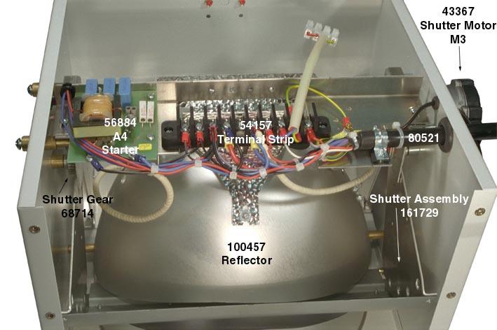
28 Power Supply & Lamp Housing 28
29 PARTS LIST Power Supply Violux VT4, VT6 & VT8 Tri-Level Printing Light VT 4 VT 6 VT 8 Symbol Description Part# Part# Part# A1 Shutter Rectifier A2 Blower Motor, PCB C1 Capacitor, Power Line Compensation (x4) (x6) (x6) C2 Capacitor, Low Cooling C3 Capacitor, Medium Cooling F1 Fuse, Main Power Control, 4 Amp F2 Fuse, Fan & Blower Circuit, 2 Amp F3 & F4 Fuse, Shutter, 4 Amp F5 Fuse, 1 Amp H1 Power ON Indicator K1 Contactor, Main Power K2 Timer, Post Cooling K3 Contactor, Exposure Timer Power Level Delay K4 Contactor, Medium to Low Power K5 Contactor, Medium to High Power Normally Closed Auxiliary Contacts L1 Choke, Reduced Power M1 Cooling Fan S1 Thermostat, Transformer Safety S2 OFF, Push Button, Red S3 ON, Push Button, Green Switch for Push Button T1 Transformer, Main Power Q1 Switch, Main Disconnect Line Cord Receptacle Complete Power Supply
30 PARTS LIST Light Unit Violux VT4, VT6 & VT8 Tri-Level Printing Light VT 4 VT 6 VT 8 Symbol Description Part# Part# Part# A4 Starter, PCB n/a C4 Capacitor, Blower Motor Starting E1 Lamp, Multi-Spectrum THS 3027 THS 6027 THS 8027 E1 Lamp, Diazo THS 3020 THS 6020 n/a E1 Lamp, Power Bulb n/a THS 6029 n/a LS1/LS2 LS1 & LS2 Limit Switch Assembly, Shutter M2 Motor, Lamp Cooling M3 Motor, Shutter Drive S4 Thermostat, Lamp Safety V1 & V2 Diode, Shutter Braking Lamp Cable Lamp Holder Gear, Shutter Motor Gear, Shutter Reflector Safety Glass Shutter Assembly Spacer, Shutter & Reflector Support Terminal Strip Screw for Terminal Strip Complete Light Unit Spacer, Shutter Bearing Bearing for Spacer Gear & Pin, Shutter
31 PARTS LIST Remote Control Box Violux VT4, VT6 & VT8 Tri-Level Printing Light VT 4 VT 6 VT 8 Symbol Description Part# Part# Part# A5 Printed Circuit Board S5/S6 Push Button, ON / OFF S7A/S7B Push Button, Power Select S9 Shutter Switch
PRINTING LAMP ASSEMBLIES DOUTHITT. 245 ADAIR ST. DETROIT, MI or TOLL FREE AT DOUTHIT(T)
") PRINTING LAMP ASSEMBLIES OPERATOR S OR S MANUAL AL DOUTHITT 245 ADAIR ST. DETROIT, MI. 48207-4287 1-313-259-1565 or TOLL FREE AT 1-800-DOUTHIT(T) 1-800-368-8448 The VIOLUX 3002s, 5002s and SUPER Light
PRINTING LAMP ASSEMBLIES OPERATOR S OR S MANUAL AL DOUTHITT 245 ADAIR ST. DETROIT, MI. 48207-4287 1-313-259-1565 or TOLL FREE AT 1-800-DOUTHIT(T) 1-800-368-8448 The VIOLUX 3002s, 5002s and SUPER Light
DOUTHITT. Theimer Printing Light Assemblies VIOLUX MULTI 4 VIOLUX MULTI 6 VIOLUX MULTI 10. Instruction Manual THE DOUTHITT CORPORATION
 Instruction Manual Theimer Printing Light Assemblies VIOLUX MULTI 4 VIOLUX MULTI 6 VIOLUX MULTI 10 DOUTHITT THE DOUTHITT CORPORATION The Douthitt Corporation, 245 Adair St., Detroit, Mich. 48207-4287 Tel.
ARC 1850 LIST OF FIGURES
 PAGE 1.0 INTRODUCTION... 1 2.0 WARRANTY... 1 3.0 UNPACKING YOUR UNIT... 1 4.0 SUGGESTED SAFETY PRECAUTIONS...... 1 4.1 PERSONAL SAFETY PRECAUTIONS. 1 4.2 POWER SUPPLY SAFETY PRECAUTIONS.. 2 5.0 GENERAL
10000AR X2 INSTALLATION MANUAL
 10000AR X2 INSTALLATION MANUAL REV 2.0b COPYRIGHT 1997 Xenotech, Inc. PAGE 1 BRITELIGHT 10000AR SPECIFICATIONS POWER SUPPLY MAIN POWER INPUT INPUT VOLTAGE: INPUT CURRENT: PHASE: FREQUENCY: 380 VAC. 20
Film-Tech. The information contained in this Adobe Acrobat pdf file is provided at your own risk and good judgment.
 Film-Tech The information contained in this Adobe Acrobat pdf file is provided at your own risk and good judgment. These manuals are designed to facilitate the exchange of information related to cinema
MD10. Engine Controller. Installation and User Manual for the MD10 Engine Controller. Full Version
 MD10 Engine Controller Installation and User Manual for the MD10 Engine Controller. Full Version File: MartinMD10rev1.4.doc May 16, 2002 2 READ MANUAL BEFORE INSTALLING UNIT Receipt of shipment and warranty
DC to AC Power Inverters
 Manufacturer of Dimensions TM Inverters 4467 White Bear Parkway St. Paul, MN 55110 Phone: 651-653-7000 Fax: 651-653-7600 E-mail: inverterinfo@sensata.com Web: www.dimensions.sensata.com ISO 9001:2000 Certified
DC to AC Power Inverters
 Manufacturer of Dimensions TM Inverters 4467 White Bear Parkway St. Paul, MN 55110 Phone: 651-653-7000 Fax: 651-653-7600 E-mail: inverterinfo@sensata.com Web: www.dimensions.sensata.com 121114C OWNERS
Dimensions 12/800N 12/1200N D. DC to AC Power Inverters. OWNERS MANUAL for Models: OWNERS MANUAL April ISO 9001:2000 Certified Company
 Manufacturer of Dimensions Inverters 4467 White Bear Parkway St. Paul, MN 55110 Phone: 651-653-7000 Fax: 651-653-7600 E-mail: inverterinfo@sensata.com Web: www.dimensions.sensata.com OWNERS MANUAL April
OPERATION/ MAINTENANCE MANUAL
 OPERATION/ MAINTENANCE MANUAL TABLE OF CONTENTS PAGE 1.0 INTRODUCTION... 1 2.0 WARRANTY... 1 3.0 UNPACKING YOUR UNIT... 1 4.0 SUGGESTED SAFETY PRECAUTIONS...... 1 4.1 PERSONAL SAFETY PRECAUTIONS. 1 4.2
24/3000H-3PH 24/4500H-3PH 24/6000H-3PH
 Manufacturer of Dimensions TM Inverters 4467 White Bear Parkway St. Paul, MN 55110 Phone: 651-653-7000 Fax: 651-653-7600 E-mail: inverterinfo@sensata.com Web: www.dimensions.sensata.com 120015D OWNERS
4000 SYSTEM OPERATING MANUAL
 4000 SYSTEM OPERATING MANUAL REV 1.4 COPYRIGHT 1996 Xenotech, Inc. PAGE 1 INSTRUCTIONS FOR REMOVING AND INSTALLING A TYPE XT XENON BULB IN A BL4000 FIXTURE NOTE FAMILIARIZE YOURSELF WITH THE LOCATION AND
Horizontal Circuit Switchers
 > Transformer Protection > CIRCUIT SWITCHERS C A T A L O G B U L L E T I N General Application Southern States Types CSH and CSH-B Horizontal Circuit Switchers provide an economical, versatile, space saving
XENON POWER SUPPLY Compact Model 220 Volt Equipment Type
 XENON POWER SUPPLY Compact Model 220 Volt Equipment Type 62-80106 62-80108 62-80109 62-80113 Rev. August 2001 STRONG INTERNATIONAL a division of Ballantyne of Omaha, Inc. 4350 McKinley Street Omaha, Nebraska
XENON POWER SUPPLY 4000 Watt Gladiator IV
 XENON POWER SUPPLY 4000 Watt Gladiator IV 220 Volt Equipment Type 62-00049 Rev. February 2003 STRONG INTERNATIONAL a division of Ballantyne of Omaha, Inc. 4350 McKinley Street Omaha, Nebraska 68112 USA
2. Description of Standard NUV Lightsource (350nm-450nm) 3 3. Description of Deep UV (220nm-280nm) and Mid UV (280nm-310nm) Lightsource Systems 3
 3 3. Description of Deep UV (220nm-280nm) and Mid UV (280nm-310nm) Lightsource Systems 3") TABLE OF CONTENTS 1. Safety Precautions 1.1 Effects of UV Radiation.. 2 1.2 Lamp Explosion. 2 1.3 Ozone Hazards. 3 1.4 Electrical Shock 3 1.5 Cooling. 3 2. Description of Standard NUV Lightsource (350nm-450nm)
TABLE OF CONTENTS 1. Safety Precautions 1.1 Effects of UV Radiation.. 2 1.2 Lamp Explosion. 2 1.3 Ozone Hazards. 3 1.4 Electrical Shock 3 1.5 Cooling. 3 2. Description of Standard NUV Lightsource (350nm-450nm)
TM-1620 OPERATING INSTRUCTIONS AND OWNERS MANUAL
 TM-1620 OPERATING INSTRUCTIONS AND OWNERS MANUAL tracopackaging.com 800-284-WRAP 620 SOUTH 1325 WEST OREM, UT. PHONE 800-284-WRAP (9727) IMPORTANT: READ ALL INSTRUCTIONS BEFORE OPERATING EQUIPMENT Your
Horizontal Circuit Switchers
 > Transformer Protection > CIRCUIT SWITCHERS C A T A L O G B U L L E T I N General Application Southern States Types CSH and CSH-B Horizontal Circuit Switchers provide an economical, versatile, space saving
XENON POWER SUPPLY Watt
 XENON POWER SUPPLY 3000-5000 Watt 220 Volt Equipment Type 62-00016 62-00017 62-00004 (Export) Rev. February 2006 STRONG INTERNATIONAL a division of Ballantyne of Omaha, Inc. 4350 McKinley Street Omaha,
MIL-24/2600Q MIL-24/3200DQ
 Manufacturer of Dimensions TM Inverters 4467 White Bear Parkway St. Paul, MN 55110 Phone: 651-653-7000 Fax: 651-653-7600 E-mail: inverterinfo@sensata.com Web: www.dimensions.sensata.com 121473B OWNER'S
Automatic taper of charge rate for superior battery life through good equalization of cells and low water use rate.
 FEATURES Automatic taper of charge rate for superior battery life through good equalization of cells and low water use rate. Silicon diodes with inherent surge protection operated at a conservative percentage
ADI-125/750 ADI-125/1500 ADI-125/2500
 Manufacturer of Dimensions TM Inverters 4467 White Bear Parkway St. Paul, MN 55110 Phone: 651-653-7000 Fax: 651-653-7600 E-mail: inverterinfo@sensata.com Web: www.dimensions.sensata.com 121094B OWNERS
XENON POWER SUPPLY for 10 kw Britelight Lamphead
 XENON POWER SUPPLY for 10 kw Britelight Lamphead Rev. June 2004 STRONG INTERNATIONAL a division of Ballantyne of Omaha, Inc. 4350 McKinley Street Omaha, Nebraska 68112 USA Tel 402/453-4444 Fax 402/453-7238
Maintenance Manual 13 AMPERE POWER SUPPLY 19A704647P1-P3. Mobile Communications LBI-31801C
 C Mobile Communications 13 AMPERE POWER SUPPLY 19A704647P1-P3 CAUTION THESE SERVICING INSTRUCTIONS ARE FOR USE BY QUALI- FIED PERSONNEL ONLY. TO AVOID ELECTRIC SHOCK DO NOT PERFORM ANY SERVICING OTHER
XENON POWER SUPPLY 2000 Watt
 XENON POWER SUPPLY 2000 Watt 220 Volt Equipment Type 6280117 Rev. February 2007 STRONG INTERNATIONAL a division of Ballantyne of Omaha, Inc. 4350 McKinley Street Omaha, Nebraska 68112 USA Tel 402/453-4444
OWNERS MANUAL JANUARY 2007 ISO
 Manufacturer of Dimensions TM Inverters 4467 White Bear Parkway St. Paul, MN 55110 Phone: 651-653-7000 Fax: 651-653-7600 E-mail: inverterinfo@sensata.com Web: www.dimensions.sensata.com OWNERS MANUAL JANUARY
Helios. 24 Light 240 Volt Controller. PRODUCT # Instruction Manual.
 Helios 14 24 Light 240 Volt Controller PRODUCT # 702832 Instruction Manual www.titancontrols.net Warnings & Cautions Helios 14 Lighting Controller Overview Instructions for Operation Troubleshooting Tips
MODEL SCA Installation and Operation Manual Important:
 MODEL SCA Installation and Operation Manual Important: This manual contains specific cautionary statements relative to worker safety. Read this manual thoroughly and follow as directed. It is impossible
Programmable Logic Controller. Mat Nor Mohamad
 Programmable Logic Controller Mat Nor Mohamad Relays Electromagnetic Control Relays The PLC's original purpose was the replacement of electromagnetic relays with a solid-state switching system that could
XENON POWER SUPPLY Watt
 XENON POWER SUPPLY 700-2500 Watt 220 Volt Equipment Type 62-00014 62-00015 62-00091 62-00093 62-00002 (Export) Rev. January 2009 STRONG INTERNATIONAL a division of Ballantyne of Omaha, Inc. 4350 McKinley
Uninterruptible Power System
 USER'S MANUAL Emergency Backup Power Supply For Use With Computer Loads Only Power Surge/Noise Protection Intelligent Auto-Shutdown Software Internet Line Protection Cost Efficiency UPS 1 st Edition Uninterruptible
CALTRAP INSTALLATION AND OPERATIONS MANUAL
 INSTALLATION AND OPERATIONS MANUAL NOTE Please read this entire installation and operations manual before energizing the. Safety Considerations: Installing and servicing capacitor equipment can be hazardous.
WARNING: FAILURE TO FOLLOW THESE RULES MAY RESULT IN SERIOUS PERSONAL INJURY CAUTION: INSTALLATION LOCATION:
 2 Please read the safety and installation instructions carefully to help ensure a correct and SAFE installation of your Second Wind Ultraviolet Germicidal Photo-catalytic Air Purifier. WARNING: FAILURE
TIME OF FLIGHT Components from:
 TIME OF FLIGHT Components from: JORDAN TOF PRODUCTS, INC. 990 Golden Gate Terrace Grass Valley, CA 95945 Phone: (530) 272-4580 Fax: (530) 272-2955 Web: www.rmjordan.com Email: info@rmjordan.com INSTRUCTION
Art. No. EC-315. Art. No. EC-330. Art. No. EC-340 SWITCH-MODE BATTTERY CHARGER CONTENTS IMPORTANT SAFETY PRECAUTIONS... 2
 SWITCH-MODE BATTTERY CHARGER CONTENTS IMPORTANT SAFETY PRECAUTIONS... 2 DESCRIPTION AND FEATURES... 3 CHARGING STAGES... 4 Art. No. EC-315 Art. No. EC-330 Art. No. EC-340 PROTECTIONS... 5 INSTALLATION...
Film-Tech. The information contained in this Adobe Acrobat pdf file is provided at your own risk and good judgment.
 Film-Tech The information contained in this Adobe Acrobat pdf file is provided at your own risk and good judgment. These manuals are designed to facilitate the exchange of information related to cinema
Training Bulletin New Model Introduction
 GE Monogram GE Consumer Service Training Training Bulletin New Model Introduction October 2001/ TB-14-01 ZV950SDSS Wall-Mount Euro-Style High Performance Vent Hood Purpose To introduce the new wall-mount
NSGV PT-1000 PORTABLE WELDING STATION I, O & M MANUAL
 APPLICATION OF DUST CONTROL EQUIPMENT: CAUTION - Warning Improper operation of dust control system may contribute to conditions in the work area or facility that could result in severe personal injury
Mini Convex HID Fog Lights
 Mini Convex HID Fog Lights 95058 INSTALLATION And Operation Instructions Due to continuing improvements, actual product may differ slightly from the product described herein. 3491 Mission Oaks Blvd., Camarillo,
INDEX Section Page Number Remarks
 INDEX Section Page Number Remarks Synchronous Alternators 2 4 General Fault Finding Capacitors 5 6 Fault Finding & Testing Diodes,Varistors, EMC capacitors & Recifiers 7 10 Fault Finding & Testing Rotors
TIME OF FLIGHT Components from:
 TIME OF FLIGHT Components from: JORDAN TOF PRODUCTS, INC. 990 Golden Gate Terrace Grass Valley, CA 95945 Phone: (530) 272-4580 Fax: (530) 272-2955 Web: www.rmjordan.com Email: info@rmjordan.com INSTRUCTION
Controlled Ferroresonant Ballast (CFB) Generation #3. Manual
 Generation #3. Manual") Controlled Ferroresonant Ballast (CFB) Generation #3 Manual SHAPE LLC 2105 Corporate Dr. Addison, IL 60101 (630) 620-8394 Toll Free (800) 367-5811 FAX (630) 620-0784 CONTENTS GENERAL DESCRIPTION... 3 INSTALLATION...
Controlled Ferroresonant Ballast (CFB) Generation #3 Manual SHAPE LLC 2105 Corporate Dr. Addison, IL 60101 (630) 620-8394 Toll Free (800) 367-5811 FAX (630) 620-0784 CONTENTS GENERAL DESCRIPTION... 3 INSTALLATION...
OWNERS MANUAL JANUARY 2007 ISO
 Manufacturer of Dimensions TM Inverters 4467 White Bear Parkway St. Paul, MN 55110 Phone: 651-653-7000 Fax: 651-653-7600 E-mail: inverterinfo@sensata.com Web: www.dimensions.sensata.com 121231B OWNERS
INSTALLATION INSTRUCTIONS
 INSTALLATION INSTRUCTIONS Universal Air Series!! NOTE!! Covers the following model: 6000 Series 85-0100B-AZ Rev 0 5/07 To ensure that the system is installed properly, provide your electrician with these
User s Manual. ACH550-CC/CD Packaged Drive with Classic Bypass Supplement for ACH550-UH HVAC User s Manual
 User s Manual ACH550-CC/CD Packaged Drive with Classic Bypass Supplement for ACH550-UH HVAC User s Manual ii ACH550-CC/CD Packaged Drive with Classic Bypass ACH550 Drive Manuals GENERAL MANUALS ACH550-UH
USER MANUAL. 10KV Digital High Voltage Insulation Tester. Model MG500. Additional User Manual Translations available at
 USER MANUAL 10KV Digital High Voltage Insulation Tester Model MG500 Additional User Manual Translations available at www.extech.com Introduction Thank you for selecting the Extech Instruments Model MG500.
POWER SUPPLY MODEL XP-800. TWO AC VARIABLE VOLTAGES; 0-120V and 7A, PLUS UP TO 10A. Instruction Manual. Elenco Electronics, Inc.
 POWER SUPPLY MODEL XP-800 TWO AC VARIABLE VOLTAGES; 0-120V and 0-40V @ 7A, PLUS 0-28VDC @ UP TO 10A Instruction Manual Elenco Electronics, Inc. Copyright 1991 Elenco Electronics, Inc. Revised 2002 REV-I
Matrix APAX. 380V-415V 50Hz TECHNICAL REFERENCE MANUAL
 Matrix APAX 380V-415V 50Hz TECHNICAL REFERENCE MANUAL WARNING High Voltage! Only a qualified electrician can carry out the electrical installation of this filter. Quick Reference ❶ Performance Data Pages
ITS-50R TRANSFER SWITCH OWNER S MANUAL
 ITS-50R OWNER S MANUAL IOTA Engineering Transfer Switches provide automatic power switching between two or three separate 120/240 volt AC input sources, including powercords, onboard generators, onboard
GretagMacbeth. Operators & Service Manual For Spectralight Models SPL-65/SPL-75
 GretagMacbeth Operators & Service Manual For Spectralight Models SPL-65/SPL-75 Issue Date: 1987 Table of Contents Section 1 General Information General Description 2 Major Components and Construction Features
Battery Control Center - Diesel
 Service Manual CAUTION: All servicing of the Battery Control Center should be done only by a qualified Service Technician. Inadvertent shorts inside the Battery Control Center could result in severe damage
Electropneumatic Timing Relays Series 7000 Industrial
 DESIGN FEATURES Available in On-Delay, True Off-Delay, and On/Off-Delay. Timing from 0.1 seconds to 60 minutes, fully calibrated in linear increments. Oversize time-calibrated adjustment knobs, serrated
C1000 Series Automatic Cap Bank
 C1000 Series Automatic Cap Bank Metal Enclosed - Medium Voltage Capacitors Assemblies Fixed / Auto Medium Voltage 5, 15, 25 and 35 kv Class Customized to your specifications The Reactive Power Solution
Troubleshooting Guide: 355 Lights (12V)
") Troubleshooting Guide: 355 Lights (12V) Contents Description Refer To: Troubleshooting - Troubleshooting Chart Adjustments / Repair Procedures Bulb Replacing the Bulb Fuse(s) Replacing the Fuse (Ceiling)
Troubleshooting Guide: 355 Lights (12V) Contents Description Refer To: Troubleshooting - Troubleshooting Chart Adjustments / Repair Procedures Bulb Replacing the Bulb Fuse(s) Replacing the Fuse (Ceiling)
8 Light Controller. Instruction Manual. With Light Timer 240 Volts. Product # INNOVATING SINCE 1995
 8 Light Controller With Light Timer 240 Volts Product #703008 Instruction Manual INNOVATING SINCE 1995 1 www.titancontrols.net 8 Light Controller This manual covers the following: Warnings & Cautions 8
TYPE KF UNDER-FREQUENCY RELAY A. Figure 1: Type KF Relay for 60 Hertz without Case. (Front & Rear View.) Front View Rear View
 Front View Rear View") 41-503.21A TYPE KF Front View Rear View Figure 1: Type KF Relay for 60 Hertz without Case. (Front & Rear View.) 2 TYPE KF 41-503.21A lower pin bearing, which is mounted on the frame, with respect to the
41-503.21A TYPE KF Front View Rear View Figure 1: Type KF Relay for 60 Hertz without Case. (Front & Rear View.) 2 TYPE KF 41-503.21A lower pin bearing, which is mounted on the frame, with respect to the
Technical Information Guide
 Revised 09/1/08 Technical Information Guide www.sunlightsupply.com www.nationalgardenwholesale.com IMPORTANT PRODUCT INFORMATION READ IMMEDIATELY KEEP ORIGINAL PACKAGING ALL RETURNS NEED TO BE IN THE ORIGINAL
PORTABLE CURRENT SOURCE FOR CIRCUIT BREAKER AND MOTOR OVERLOAD TESTING INSTRUCTION MANUAL PI-250B. Release 1.0 April 5, 2013
 PORTABLE CURRENT SOURCE FOR CIRCUIT BREAKER AND MOTOR OVERLOAD TESTING INSTRUCTION MANUAL PI-250B Release 1.0 April 5, 2013 Electrical Test Instruments, Inc. 1301 Avondale Road, Suite J New Windsor, MD
REFERENCE MANUAL FORM: MX-TRM-E REL REV MTE
 Matrix APAX 380V-415V 50Hz TECHNICAL REFERENCE MANUAL FORM: MX-TRM-E REL. September 2014 REV. 002 2014 MTE Corporation WARNING High Voltage! Only a qualified electrician can carry out the electrical installation
Raydot LLC 24 Actuator (115 VOLT)
") Installation, Operation & Parts Manual Read carefully the information provided. Retain manual for future reference. Raydot LLC 24 Actuator (115 VOLT) 145 Jackson Ave. S. Cokato, MN 55321-USA (320) 286-2103
Installation, Operation & Parts Manual Read carefully the information provided. Retain manual for future reference. Raydot LLC 24 Actuator (115 VOLT) 145 Jackson Ave. S. Cokato, MN 55321-USA (320) 286-2103
CONTROLLIX CORPORATION CONTROLLIX.COM LOW VOLTAGE AUTOMATIC SWITCH CAPACITOR BANK SPECIFICATIONS
 LOW VOLTAGE AUTOMATIC SWITCH CAPACITOR BANK SPECIFICATIONS I. SCOPE a. This specification describes the necessary requirements for the design, fabrication, and operation of automatically switched, low
LESTRONIC II BATTERY CHARGER TAYLOR-DUNN MODEL TYPE 24LC25-8ET
 LESTRONIC II BATTERY CHARGER TAYLOR-DUNN 79-301-10 MODEL 13110-32 TYPE 24LC25-8ET AC Supply: DC Output: Battery Capacity: Specifications 120 volts, 60 Hertz, single-phase 24 volts, 32 amps Use only on
Uninterruptible Power System
 USER'S MANUAL Emergency Backup Power Supply For Use With Computer Loads Only Power Surge/Noise Protection Intelligent Auto-Shutdown Software Internet Line Protection Cost Efficiency UPS AVR Protection
Instruction Manual AVTM for. Strip Chart Recorder Catalog Nos and
 AVTM220003 Rev. B January 2003 Instruction Manual AVTM220003 for DC µa Strip Chart Recorder Catalog Nos. 220003 and 220003-47 PO Box 9007 Valley Forge, PA 19485-1007 U.S.A. 610-676-8500 Shipping Address:
LARGE CAPACITY INCUBATOR Installation, Operation and Maintenance Instructions
 LARGE CAPACITY INCUBATOR Installation, Operation and Maintenance Instructions GENERAL 2 Inspection 2 Location 2 INSTALLATION 2 Door Alignment 2 Shelf Installation 2 Remote Contacts 2 2-10 Volt DC Output
Basics of Control Components
 Basics of Control Components Table of Contents Introduction...2 Electrical Symbols...6 Line Diagrams...16 Overload Protection...22 Overload Relays...26 Manual Control...35 Magnetic Contactors and Starters...41
High Frequency SineWave Guardian TM
 High Frequency SineWave Guardian TM 380V 480V INSTALLATION GUIDE FORM: SHF-IG-E REL. January 2018 REV. 002 2018 MTE Corporation High Voltage! Only a qualified electrician can carry out the electrical installation
SERVICE MANUAL (INTERNATIONAL)
") SERVICE MANUAL (INTERNATIONAL) IMPINGER CONVEYOR OVENS MODEL 1421-000-E, 1454, 1455 WITH PUSH BUTTON CONTROLS Lincoln Foodservice Products, LLC 1111 North Hadley Road Fort Wayne, Indiana 46804 United States
SERVICE MANUAL (INTERNATIONAL) IMPINGER CONVEYOR OVENS MODEL 1421-000-E, 1454, 1455 WITH PUSH BUTTON CONTROLS Lincoln Foodservice Products, LLC 1111 North Hadley Road Fort Wayne, Indiana 46804 United States
Direct Gas-Fired Heating
 Direct Gas-Fired Heating Model DG 800 to 15,000 cfm Up to 1,600,000 BTU/hr Optional Evaporative Cooling January 2005 PRODUCT FEATURES Model DG Direct Gas-Fired Make-Up Air Unit The Greenheck model DG is
3.0 CHARACTERISTICS E Type CO-4 Step-Time Overcurrent Relay
 41-106E Type CO-4 Step-Time Overcurrent Relay A core screw accessible from the top of the switch provides the adjustable pickup range. The IIT contacts are connected in the trip circuit to trip instantaneously.
MAHALAKSHMI ENGINEERING COLLEGE TIRUCHIRAPALLI
 MAHALAKSHMI ENGINEERING COLLEGE TIRUCHIRAPALLI 621213 QUESTION BANK --------------------------------------------------------------------------------------------------------------- Sub. Code : EE2402 Semester
MAGNETIC MOTOR STARTERS
 Chapter 6 MAGNETIC MOTOR STARTERS 1 The basic use for the magnetic contactor is for switching power in resistance heating elements, lighting, magnetic brakes, or heavy industrial solenoids. Contactors
FOR INDOOR/SEASONAL USE ONLY
 9' Warm White /Multi LED Color Changing One Plug Tree V66362-60 INSTRUCTION MANUAL Thank you for purchasing a SYLVANIA Pre-lighted Tree. This tree assembles in minutes and is decorated with energy saving
X4 Installation and Operation Manual - POWER FLAME INCORPORATED
 7.13.2 Set the burner s combustion air inlet damper to the approximate setting as shown in this manual for the desired firing rate. Also, verify that the correct main orifice is installed in the main orifice
STATIC DAYLIGHT PAR 575 VF
 STATIC LIGHT COMPANY LIMITED Unit 11, Meridian Business Park Fleming Road WALTHAM ABBEY EN9 3BZ www.staticlightcompany.com info@staticlightcompany.com TEL +44 (0) 1992 766 766 THIS INFORMATION IS DESIGNED
CLEAN AIR WORKSTATION REVERSE FLOW. Installation and Operations Manual
 CLEAN AIR WORKSTATION REVERSE FLOW Installation and Operations Manual CLEAN AIR WORKSTATION REVERSE FLOW Installation and Operations Manual Revision: 16-Jan-17 Page 1 of 12 CLEAN AIR WORKSTATION REVERSE
User s Manual. ACH550-CC/CD Packaged Drive with Classic Bypass Supplement for ACH550-UH HVAC User s Manual
 User s Manual ACH550-CC/CD Packaged Drive with Classic Bypass Supplement for ACH550-UH HVAC User s Manual ii ACH550-CC/CD Packaged Drive with Classic Bypass ACH550 Drive Manuals GENERAL MANUALS ACH550-UH
1200+ WITH LVD (LOW VOLTAGE DISCONNECT) USER GUIDE
 USER GUIDE") 1200+ WITH LVD (LOW VOLTAGE DISCONNECT) USER GUIDE INST045 Doc 2.00 CONTENTS General Information...2 Operating Environment...6 Features...7 Installation Instructions...8 Inverter Ground and Remote Sense
1200+ WITH LVD (LOW VOLTAGE DISCONNECT) USER GUIDE INST045 Doc 2.00 CONTENTS General Information...2 Operating Environment...6 Features...7 Installation Instructions...8 Inverter Ground and Remote Sense
SHORT-STOP. Electronic Motor Brake Type G. Instructions and Setup Manual
 Electronic Motor Brake Type G Instructions and Setup Manual Table of Contents Table of Contents Electronic Motor Brake Type G... 1 1. INTRODUCTION... 2 2. DESCRIPTION AND APPLICATIONS... 2 3. SAFETY NOTES...
24 Linear Actuator 115 Volts A.C. (Cat. # C430A)
") Installation, Operation & Parts Manual Read carefully the information provided. Retain manual for future reference. 24 Linear Actuator 115 Volts A.C. (Cat. # C430A) Page 1 of 8 IS10007.doc 11/15/06 IMPORTANT!
Installation, Operation & Parts Manual Read carefully the information provided. Retain manual for future reference. 24 Linear Actuator 115 Volts A.C. (Cat. # C430A) Page 1 of 8 IS10007.doc 11/15/06 IMPORTANT!
Troubleshooting Guide: 355 Lights (24V)
") Troubleshooting Guide: 355 Lights (24V) Contents Description Refer To: Troubleshooting - Troubleshooting Chart Adjustments / Repair Procedures Bulb Replacing the Bulb Fuse(s) Replacing the Fuse (Ceiling)
Troubleshooting Guide: 355 Lights (24V) Contents Description Refer To: Troubleshooting - Troubleshooting Chart Adjustments / Repair Procedures Bulb Replacing the Bulb Fuse(s) Replacing the Fuse (Ceiling)
KenkoAir_Purifier manual ENG-FR_FDA 10/12_Air Filter manual 8/15/13 10:44 AM Page 1 OPERATING MANUAL
 KenkoAir_Purifier manual ENG-FR_FDA 10/12_Air Filter manual 8/15/13 10:44 AM Page 1 OPERATING MANUAL KenkoAir_Purifier manual ENG-FR_FDA 10/12_Air Filter manual 8/15/13 10:44 AM Page 2 PRODUCT INTRODUCTION
9' Warm White /Multi LED Color Changing M5 One Plug tree V INSTRUCTION MANUAL
 9' Warm White /Multi LED Color Changing M5 One Plug tree V64886-60 INSTRUCTION MANUAL Thank you for purchasing a SYLVANIA Pre-lighted Tree. This tree assembles in minutes and is decorated with energy saving
Matrix AP 400V 690V INSTALLATION GUIDE. Quick Reference. ❶ How to Install Pages 6 20 ❷ Startup/Troubleshooting Pages WARNING
 Matrix AP 400V 690V INSTALLATION GUIDE FORM: MAP-IG-E REL. May 2017 REV. 002 2017 MTE Corporation WARNING High Voltage! Only a qualified electrician can carry out the electrical installation of this filter.
Junior Sandblaster. Model #51 WARNING! FOR YOUR SAFETY PLEASE READ INSTRUCTIONS BEFORE OPERATING TOOL & WEAR EYE PROTECTION
 Junior Sandblaster Model #51 WARNING! FOR YOUR SAFETY PLEASE READ INSTRUCTIONS BEFORE OPERATING TOOL & WEAR EYE PROTECTION PARTS LIST AND PART NUMBERS 01.Red Rubber Air Hose (5Ft) P51-01 02. Male Insert
SE2000BX Static Exciter
 Rev 3 SE2000BX Static Exciter The SE2000BX Static Exciter is designed to replace most electronic, saturable reactor and rotary exciters used on slip ring or rotor fed electric generators. The SE2000BX
(For serial numbers before w/ analog control)
") SEQUENCE OF OPERATIONS (For serial numbers before 2038616 w/ analog control) MODEL 1154-000-EA NAT. GAS 230 VAC 50 HZ. 1 PHASE MODEL 1155-000-EA LP GAS 230 VAC 50 HZ. 1 PHASE POWER SUPPLY Electrical power
SEQUENCE OF OPERATIONS (For serial numbers before 2038616 w/ analog control) MODEL 1154-000-EA NAT. GAS 230 VAC 50 HZ. 1 PHASE MODEL 1155-000-EA LP GAS 230 VAC 50 HZ. 1 PHASE POWER SUPPLY Electrical power
COOKSON OWNER'S MANUAL
 COOKSON OWNER'S MANUAL FDO-A10 INDUSTRIAL DUTY FIRE DOOR OPERATOR R L I S T E D 3040233 US CONTROL PANEL SERIAL# OPERATOR SERIAL# 9001.DWG ECN 0959 REV 4 SPECIFICATIONS MOTOR TYPE:...INTERMITTENT HORSEPOWER:...1/8
MODEL ELC-12/40-CVM-D BATTERY CHARGER
 NATIONAL RAILWAY SUPPLY MODEL ELC-12/40-CVM-D BATTERY CHARGER Installing, Operating and Service Instructions for the ELC-12/40-CVM-D Solid State Charger PLEASE SAVE THESE IMPORTANT SAFETY AND OPERATING
Northwest RV Supply Manual Compliments of Printed From TROUBLESHOOTING
 TROUBLESHOOTING for the 5 BUTTON 3109228.001 COMFORT CONTROL CENTER SYSTEM INTRODUCTION The Comfort Control Center control system can be used to operate the following Duo-Therm Units: Roof Top Air Conditioners
Transfer Switch GPTS 30
 Transfer Switch GPTS 30 Owner s Manual Table of Contents Introduction 2 Installation 3 Operational Testing 7 Troubleshooting 8 Hi-Pot Testing 9 Generator Note 10 Medical Appliances 10 Caution 10 Warranty
PARTS & SERVICE MANUAL
 PARTS & SERVICE MANUAL Impinger Low Profile Advantage Digital Series (Electric) International Models MODELS: Please note that the model numbering system changed March 2007. The chart below shows the old
2.0 CONSTRUCTION 3.0 OPERATION. SA-1 Generator Differential Relay - Class 1E 2.5 TRIP CIRCUIT
 41-348.11C SA-1 Generator Differential Relay - Class 1E 2.0 CONSTRUCTION The type SA-1 relay consists of: Restraint Circuit Sensing Circuit Trip Circuit Surge Protection Circuit Operating Circuit Amplifier
BL7000 SYSTEM OPERATING MANUAL
 BL7000 SYSTEM OPERATING MANUAL REV 2.0 208 / 230V COPYRIGHT 1995 Xenotech, Inc. PAGE 1 POWER INPUT CONNECTOR WIRING INSTRUCTIONS THE INPUT POWER REQUIREMENTS FOR A 7 KW POWER SUPPLY ARE AS FOLLOWS. VOLTAGE
I1 7.5 Pre-Lit Clear Christmas Tree
 I1 7.5 Pre-Lit Clear Christmas Tree 62432-13 INSTRUCTION MANUAL Thank you for purchasing this Pre-lighted Tree. This tree assembles in minutes and is decorated with UL listed miniature light sets. Please
SECTION DC POWER SUPPLY/BATTERY CHARGER
 SECTION 26 33 05 PART 1 - GENERAL 1.1 THE REQUIREMENT A. The CONTRACTOR shall provide the single-phase heavy-duty industrial battery charger and all accessories required, complete and operable, in accordance
User s Manual. Automatic Switch-Mode Battery Charger
 User s Manual Automatic Switch-Mode Battery Charger IMPORTANT Read, understand, and follow these safety rules and operating instructions before using this battery charger. Only authorized and trained service
ST Charger. Industrial Battery Charger
 ST Charger Industrial Battery Charger Installation and Operation Manual ST_13 Table of Contents Pg# 1.0 INSTALLATION 1 1.1 Receiving 1 1.2 Location 1 1.3 Line Voltage 1 1.4 A.C. Service Requirements 2
9 HID OFF-ROAD LIGHT
 9 HID OFF-ROAD LIGHT 95059 INSTALLATION And Operation Instructions Diagrams within this manual may not be drawn proportionally. Due to continuing improvements, actual product may differ slightly from the
HIB Enclosed Inverter User Guide
 HIB Enclosed Inverter User Guide (0.75kW~22kW) V1.2.0 Contents 1 Safety information...1 2 Technical Data...2 3 Motor Connection...4 4 Operation...5 5 Single phase circuit diagram...7 6 Three phase circuit