WARNING: FAILURE TO FOLLOW THESE RULES MAY RESULT IN SERIOUS PERSONAL INJURY CAUTION: INSTALLATION LOCATION:
|
|
|
- James Smith
- 5 years ago
- Views:
Transcription


1
2 2
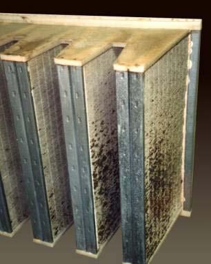
3 Please read the safety and installation instructions carefully to help ensure a correct and SAFE installation of your Second Wind Ultraviolet Germicidal Photo-catalytic Air Purifier. WARNING: FAILURE TO FOLLOW THESE RULES MAY RESULT IN SERIOUS PERSONAL INJURY 1 Read instruction manual before operating the units. 2 Eye damage may result from directly viewing the light produced by these lamps. To reduce the risk of exposure to UV radiation, take UV-radiation protective measures for personnel during servicing. 3 This fixture is designed for use with germicidal UV-C lamps and must be installed in compliance with competent technical directions so that user s eyes and bare skin will not be subjected to injurious rays. 4 UV Light Hazard. To prevent exposure to ultraviolet light, be sure the ultraviolet air treatment system is disconnected before servicing any part of the HVAC system or removing any access panel or the equivalent. 5 There shall not be any openings in the duct that would emit light. 6 There shall not be any duct supply or return air openings or any other openings that are in direct line-of-sight of the UV bulb. 7 Check damaged parts: Before further use of the unit, any damaged part should be carefully checked to ensure that the unit will operate properly. Any part that is damaged should be properly repaired or replaced. 8 Always service unit with Second Wind replacement parts & recommended accessories (i.e. lamps, ballast). CAUTION: 1 Personal Injury Hazard. Power supply can cause electrical shock. Disconnect power supply before servicing or beginning installation. 2 Risk of exposure to excessive ultraviolet (UV) radiation Do not operate without complete lamp enclosure in place or if sight lens is damaged. 3 Equipment Damage Hazard. Ultraviolet light can cause color shift or surface degradation and sometimes structural degradation of non-metallic components. Select mounting location that prevents exposure to plastic flexible duct components, polyurethane foam insulation material, rubber hoses, wire insulations, etc. If mounting options are limited, items above should be protected with ultraviolet resistant materials such as aluminum foil, aluminum duct tape, or metallic shields. INSTALLATION LOCATION: 1. See page 4 for possible installation locations. 2. Products shall be mounted only on to metal air ducts. 3. Mounting shall be such that all surfaces in the duct where appliance forms parts of the duct shall be made of metal. 4. All wiring within adjacent heating and air conditioning equipment, for example, shall be shaded from direct line-of-sight from the UV bulb or shall be UV-rated. Second Wind Ultraviolet Germicidal Photo-catalytic Air Purifiers are designed for the treatment of evaporator coils used in commercial and rooftop air handling units (AHU s) HVAC systems. The lamps will kill microorganisms growing on evaporator coils and drain pans and prevent further growth. The units are designed for continuous lamp operation. The commercial units are 120/277 VAC single and dual lamp units. See pages for unit specifications. 3
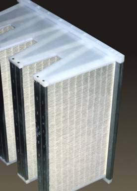
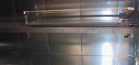
4 The installation should be done by a qualified HVAC contractor in the supply or return side. Read all safety instructions at the beginning of this manual. Failure to do so could lead to personal injury and/or equipment damage. In cases where fungi and/or bacteria are already present on the evaporator coil, it is recommended that a qualified HVAC technician clean the coil before the installation of the UV lamp. Because the Second Wind Commercial Ultraviolet Germicidal Photo-catalytic Air Purifier quickly kills fungi and bacteria, there could be an initial period of temporarily increased levels of airborne decay products if the coil is not cleaned before installation. Safety interlock switches for the access panel are recommended but not supplied. Unistrut may be used to support the unit ( not supplied) There can only be a maximum of units installed in parallel. TOOLS Electric Drill with drill bits ( 3/32 ) Saw to cut stainless track to fit # 10 Nut Driver or socket set Tape Measure Alcohol Wipe ( In case lamps are touched) Eye protection Digital multi meter may also be needed 1. Determine a mounting location for the lamp. Use the criteria below to select a proper location: The lamps are intended for evaporator coil treatment. The lamps install in a air handling system, the NEMA enclosure allows for installation indoors or outdoors. Install lamp in location that prevents exposure of plastics, rubber, paper, and other non-metallic materials to UV light, or shield such materials with aluminum tape, sheet metal, or metal conduit. See CAUTION statements at beginning of manual for more details. To protect the lamp, do not install lamp below any source of water. Install units so that the lamp assembly is at least 3 inches away from evaporator surface. Install lamp in a location that can be easily accessed Be certain the area in the duct where you intend to drill and cut is free of any obstructions or components that would be damaged by the installation or interfere with the installation. While keeping these guidelines in mind, the more direct exposure the coil and drain pan receive, the greater the benefit the lamps will have. 2. Carefully inspect the HVAC system and make sure no damage will occur as a result of drilling the holes. 3. Mounting holes are pre-punched in each unit making installation a screw-on procedure using the supplied #10 sheet metal screws. Different mounting hardware may be needed depending on installation. 4. Place warning labels (included) on the duct: one on the duct near the UV lamp and the other near the air handler. 5. With the cover of the commercial unit is still open access the ballast and wiring. Remove one of the electrical knockouts and send the wiring through the hole. Connect the electrical service, connect the black and white wires to power (depending on 120V thru 277V) and the green wire to ground. When wiring multiple units together 1/2 inch conduit nipples are provided to connect fixtures. Refer to Section IX pages If installing multiple units wire each row in parallel using #18 fixture wire (SOL TFN, 600V, 105C). Wire units through a properly rated DPDT access door interlock switch, to a suitable, protected and grounded power source, in accordance with applicable codes. Refer to Section IX. 7. For finish wiring, use EMT or metal flex (when exposed to UVC) to protect wire insulation. 8. All connections are to be readily visible for inspection when the cover is taken off. 9. Attach the cover, then attach reflector plate. 10. Use the alcohol wipe to remove any dirt or fingerprints from the lamp. 11. Make sure the lamp connector is attached to the lamp. There is only one way to attach the connector to the lamp. Snap the lamp into the lamp holders. 12. Turn on electrical service, unit is always energized. 4
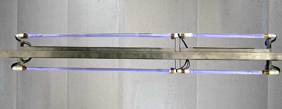
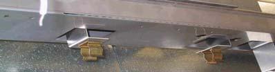
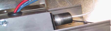
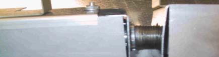
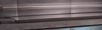
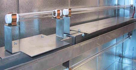
5 1. Determine a mounting location for the lamp. Use the criteria below to select a proper location: The lamps are intended for evaporator coil treatment. The lamps install in a air handling system, the NEMA enclosure allows for installation indoors or outdoors. Install lamp in location that prevents exposure of plastics, rubber, paper, and other non-metallic materials to UV light, or shield such materials with aluminum tape, sheet metal, or metal conduit. See CAUTION statements at beginning of manual for more details. To protect the lamp, do not install lamp below any source of water. Install units so that the lamp assembly is at least 3 inches away from evaporator surface. Install lamp in a location that can be easily accessed Be certain the area in the duct where you intend to drill and cut is free of any obstructions or components that would be damaged by the installation or interfere with the installation. While keeping these guidelines in mind, the more direct exposure the coil and drain pan receive, the greater the benefit the lamps will have. 2. Carefully inspect the HVAC system and make sure no damage will occur as a result of drilling the holes. 3. Mounting holes are pre-punched in each unit making installation a screw-on procedure using the supplied #10 sheet metal screws. Different mounting hardware may be needed depending on installation. 4. Chose a mounting location, using the duct mounting track holders and the installation track, install first row of units. Each row should be installed within 6 feet of each other. If available an installation layout drawing will designate measurements between, duct and other rows of units. Attach duct mounting track holders at appropriate measurement with #10 self tapping sheet metal screws or pre-drill pilot hole with 3/32 drill bit. Lay track in track holders and secure with screws. If length of track is beyond 6 feet, track connectors will have to be used, and unistrut may be used to support track at connections every 3 feet. Picture s 1-4 page 11. Unistrut example page 19. NOTE: Distances between units on the track will vary between 2 1/4 and 3 inches depending on the configu- 5. Place dual lamp unit in track. There are various rectangular cutouts in the track, depending on the length of the track install units in appropriate cutouts. Remove cover of unit and secure unit to track through pre-punched holes. Add as many units as necessary to go the length of the track, attaching the units together by the 1/2 inch conduit nipples provided, and securing with #10 sheet metal screws through pre-punched holes in unit. Picture s 5-9 page Place warning labels (included) on the duct: one on the duct near the UV lamp and the other near the air handler. 7. With the cover of the commercial unit is still open access the ballast and wiring. Send the wiring through the hole and 1/2 inch conduit. Connect the ballast in parallel, connect the black and white wires to power (depending on 120V or 277V) and the green wire to ground. Refer to the wiring diagram page 13. When wiring multiple units together 1/2 inch conduit nipples are provided to connect fixtures. Refer to Section IX pages If installing multiple units wire each row in parallel using #18 fixture wire (SOL TFN, 600V, 105C). Wire units through a properly rated DPDT access door interlock switch, to a suitable, protected and grounded power source, in accordance with applicable codes. Refer to Section IX. 9. For finish wiring, use EMT or metal flex (when exposed to UVC) to protect wire insulation. 10. All connections are to be readily visible for inspection when the cover is taken off. 11. Attach the covers, then attach reflector plates, with the screws and nuts provided. Picture 10 page Use the alcohol wipe to remove any dirt or fingerprints from the lamp. 13. Make sure the lamp connector is attached to the lamp. There is only one way to attach the connector to the lamp. Snap the lamp into the lamp holders. Picture s page Turn on electrical service, unit is always energized Ballast Green Wire To Ground To 120V- 277V Electrical Service and Interlock switch 5
6 The Second Wind Commercial Ultraviolet Germicidal Photo-catalytic Air Purifier is designed for the lamp to be on at all times. After 9000 hours of operation 1 year of continuous use the effectiveness of the lamp inside the duct diminishes and should be replaced. Rarely will a lamp burn out in one year of continuous use; replacement is necessary because the lamp s intensity decreases. Installation of the replacement lamp is best handled by a qualified HVAC Service Contractor. The installation should be done by a qualified HVAC contractor. Disconnect electrical service Disconnect the lamp connector from the lamp base. Remove old lamp from the lamp holders ( Be careful old lamp may still be hot! ). Replace the old lamp with the new lamp, making sure the new lamp is clean. If the new lamp is dirty or has fingerprints on it remove with an alcohol wipe. Place lamp into lamp holders. Attach lamp connector to the lamp. Record the date lamp was replaced. As with a fluorescent light bulb, your UV lamp contains mercury and must be disposed of properly. Do not throw old lamps into the trash. Many communities have agencies that take in mercury along with other materials such as old paint, solvents, etc. that require special disposal. Please contact your municipal or county waste collection agency for proper disposal procedures. If a lamp is broken, do not use a vacuum cleaner to pick up the waste. Instead, sweep up the waste into a plastic bag and seal. Contact your municipal or county waste collection agency for proper disposal procedures. 9 inch replacement lamp 1068AR 18 inch replacement lamp 1076R 36 inch replacement lamp R Ballast..5000BR 6


7 If the lamps do not illuminate, check the following: Electrical Supply/Wiring Verify that the electrical service is operating correctly and all units are wired together properly. Fuse If the lamp is still not illuminated, turn off electrical supply and check the fuse. Look to see if FUSE is darkened or visibly blown; or check fuse continuity with multi-meter. Ballast If lamp still is not illuminating check the wiring to the ballast. If the ballast is wired properly and the lamp still does not illuminate, replace the ballast. With a fully electronic ballast there is no resistance testing. Lamp Verify that the lamp is not broken and is properly seated in the lamp connector. To check this, follow steps in the Annual Lamp Replacement section with one exception : you should not remove and replace the lamp. If the lamp is broken read the Lamp Disposal 7


8 8
9 Wiring for multiple 5036DL units together in a track : Figure Feed green, white and black wires from the source into first 5036DL unit. 2. Ground green from the source to the internal stud. ( Initial unit must have source ground attached to the stud or ground to the mounting track.) 3. Make sure the green ground from each ballast is also attached to the internal grounding stud. 4. Take the black wire from the source, the black wires from each ballast, and a black jumper wire ( minimum #18 solid wire 600 volt, 105 C.) long enough to reach into the next unit and wire that unit. 5. Using terminal block wire the 4 black wires together and feed the black jumper wire into the second 5036DL unit. 6. Take the white wire from the source, the white wires from each ballast, and a white jumper wire ( minimum #18 solid wire 600 volt, 105 C.) long enough to reach into the next unit and wire that unit. 7. Using terminal block wire the 4 white wires together and feed the white jumper wire into the second 5036DL unit. 8. Using terminal block wire the 2 black ballast wires in the next unit to the black jumper wire from the previous unit. 9. Using terminal block wire the 2 white ballast wires in the next unit to the white jumper wire from the previous unit. 10. Make sure the 2 green ballast ground wires are attached the internal grounding stud. 11. Follow directions 4-10 to wire all subsequent 5036DL units. 12. All connections are to be readily visible for inspection when the cover is taken off. 13. Total rating for all combinations is 20 amps. Terminal Block Black Jumper Wire Terminal Block Source Ballast Ballast Ballast Ballast Green Ground White Jumper Wire Green Ground Wiring for 5036DL unit to (5018DL or 5009DL) unit in a track : Figure Feed green, white and black wires from the source into first 5036DL unit. 2. Ground green from the source to the internal stud. ( Initial unit must have source ground attached to the stud or ground to the mounting track.) 3. Make sure the green ground from each ballast is also attached to the internal grounding stud. 4. Take the black wire from the source, the black wires from each ballast, and a black jumper wire ( minimum #18 solid wire 600 volt, 105 C.) long enough to reach into the next unit and wire that unit. 5. Using terminal block wire the 4 black wires together and feed the black jumper wire into the second (5018DL or 5009DL) unit. 6. Take the white wire from the source, the white wires from each ballast, and a white jumper wire ( minimum #18 solid wire 600 volt, 105 C.) long enough to reach into the next unit and wire that unit. 7. Using terminal block wire the 4 white wires together and feed the white jumper wire into the second (5018DL or 5009DL) unit. 8. Using terminal block wire the 1black ballast wire in the next unit to the black jumper wire from the previous unit. 9. Using terminal block wire the 1 white ballast wire in the next unit to the white jumper wire from the previous unit. 10. Make sure the 1 green ballast ground wire is attached the internal grounding stud. 11. All connections are to be readily visible for inspection when the cover is taken off. 12. Total rating for all combinations is 20 amps. Terminal Block Black Jumper Wire Terminal Block Source Ballast Ballast Ballast Green Ground White Jumper Wire Green Ground 9
10 Wiring for 5036SL-5036SL, 5036SL-5018SL, 5036SL-5009SL, 5018SL-5009SL, or 5018DL-5009DL units together : Figure Feed green, white and black wires from the source into first DL or SL unit. 2. Ground green from the source to the internal stud. ( Initial unit must have source ground attached to the stud or ground to the mounting track.) 3. Make sure the green ground from each ballast is also attached to the internal grounding stud. 4. Take the black wire from the source, the black wire from ballast, and a black jumper wire ( minimum #18 solid wire 600 volt, 105 C.) long enough to reach into the next unit. 5. Using terminal block wire the 3 black wires together and feed the black jumper wire into the next SL or DL unit. 6. Take the white wire from the source, the white wire from ballast, and a white jumper wire ( minimum #18 solid wire 600 volt, 105 C.) long enough to reach into the next unit. 7. Using terminal block wire the 3 white wires together and feed the white jumper wire into the next SL or DL unit. 8. Using terminal block wire the 1black ballast wire in the next unit to the black jumper wire from the previous unit. 9. Using terminal block wire the 1 white ballast wire in the next unit to the white jumper wire from the previous unit. 10. Make sure the 1 green ballast ground wire is attached the internal grounding stud. 11. All connections are to be readily visible for inspection when the cover is taken off. 12. Total rating for all combinations is 20 amps. Terminal Block Black Jumper Wire Terminal Block Source Ballast Ballast Green Ground White Jumper Wire Green Ground 10
11 All Second Wind Air Purification systems that are attached to your Heating, Ventilation and Air Conditioning System (HVAC) have a (3) three year unit warranty. The lamps for all the HVAC attached units have a (1) year warranty.(models:5036sl & DL, 5018SL & DL, 5009SL & DL ) ONE (1) YEAR COVERAGE LAMPS The lamps are warranted by Second Wind for a period of one (1) year from the date of the original installation, when installed and operated in accordance with Second Wind recommendations. If during this period a lamp fails, Second Wind will provide a free replacement. You must pay shipping charges and all other costs of warranty service. Second Wind will not pay labor involved in diagnostic calls or in removing, servicing, or replacing parts. THREE (3) YEAR COVERAGE UNIT The covered equipment and covered components are warranted by Second Wind for a period of three (3) years from the date of the original unit installation, when installed and operated in accordance with Second Wind recommendations. If during this period a covered component fails, Second Wind will repair or replace the part. You must pay shipping charges and all other costs of warranty service. Second Wind will not pay labor involved in diagnostic calls or in removing, servicing, or replacing parts. REPAIRS All repairs of covered components must be made with authorized service parts. Labor charges resulting from diagnostic calls or service are not covered by this warranty. CARE OF EQUIPMENT Your new Second Wind Air Purifier must be properly installed, operated and maintained in accordance with the unit installation, operation, and maintenance instructions provided with each unit. Failure to provide maintenance per Second Wind instructions will void warranty. 11
12 WARRANTY LIMITATIONS This warranty will be voided if the covered equipment (only second wind replacement parts or units are warranted) is removed from the original installation site. This warranty does not cover damage or defect resulting from: 1 Accident, or neglect or unreasonable use or operation of the equipment, including operation of electrical equipment at voltages other than the range specified on the unit name plate. 2 Modification, change or alteration of the equipment, except as directed by Second Wind. The furnishings of replacement parts under terms of this warranty will apply to the original warranty period and will not extend the warranty. Second Wind makes no express warranties other than the warranty specified above. All implied warranties, including the implied warranty of merchantability and fitness for a particular purpose, are limited to the duration of the warranty specified above. Liability for incidental and consequential damages is excluded and is not covered by this warranty. Some States do not allow limitations on the duration of an implied warranty or the exclusion or limitation of incidental or consequential damages, so the limitations or exclusions may not apply to you. This warranty gives you specific legal rights, and you may also have other rights which vary from state to state. Second Wind shall not be liable for any default or delay in performance under this warranty caused by any contingency beyond their control. All Second Wind Air Purification systems that are attached to your Heating, Ventilation and Air Conditioning System (HVAC) have a (3) three year limited warranty. The lamps for all the HVAC attached units have a (1) year warranty.(models:5036sl & DL, 5018SL & DL, 5009SL & DL ) 1 Be prepared to furnish the following information: a- Complete model number and serial number b- Proof of installation date if warranty claim is made by other than a qualified service dealer who maintains records of your installation date and service history. c- An accurate description of the problem. d- Date of failure. 2 Call the installing dealer that you purchased your Second Wind from. 3 If the installing dealer is unable to provide warranty parts, contact: Call, write, fax or Second Wind Air Purifiers 255 Great Arrow Avenue, Unit 20C Buffalo, NY PHONE FAX service@secondwindairpurifier.com 12
HARDWARE KIT INSTALLATION GLOVES
 COIL MOUNT STEEL DUCT MOUNT DUCTBOARD MOUNT CLAMP PLATE Z-BRACKET PCO BRACKET SHIELDED LAMP ASSEMBLY ALSO INCLUDED BALLAST TECH MANUAL HARDWARE KIT INSTALLATION GLOVES Rev 1 Issued: 09/03/2014 SERVICE
Safety, Installation and Service Manual Models 1952, 1953 & 1972
 Ultraviolet Germicidal Lamps Model 1952 24 Rooftop Unit Model 1953 32 Rooftop Unit Model 1972 Rooftop Unit, Internal Mount Safety, Installation and Service Manual Models 1952, 1953 & 1972 READ AND SAVE
UV-AIRE AIR PURIFYING SYSTEM
 UV-AIRE AIR PURIFYING SYSTEM Model: UV-16/24 The UV-Aire unit is designed to emit powerful UVC Band light rays, which sterilize and reduce airborne microorganisms as they pass through a heating or air
Model: UV-16R/24 READ THESE INSTRUCTIONS CAREFULLY AND COMPLETELY BEFORE PROCEEDING WITH THE INSTALLATION.
 U V - AIRE AIR PURIFYING S YSTEM Model: UV-16R/24 ITEMS INCLUDED IN KIT: 1-24Volt UV-Aire Ballast Assembly 1-Mounting Base 1-Ultraviolet Lamp 6-Sheet Metal Mounting Screws 1-Instruction Sheet 1-Fiberglass
READ AND SAVE THESE INSTRUCTIONS. ComfortBreeze UV360-1 SYSTEM 24V Ultra-Violet Air Cleaner. Trion
 READ AND SAVE THESE INSTRUCTIONS ComfortBreeze UV360-1 SYSTEM 24V Ultra-Violet Air Cleaner Trion www.trioniaq.com Installation, Operation, & Maintenance Manual 1. Warranty 2. Safety & Warnings ComfortBreeze
WARNING Risk of property damage, injury, or death.
 INDOOR AIR QUALITY PRODUCTS KITS AND ACCESSORIES 506412 01 10/09 Litho U.S.A. HEALTHY CLIMATE GERMICIDAL LIGHT KIT INSTALLATION & USER INSTRUCTIONS FOR HEALTHY CLIMATE GERMICIDAL LIGHT MODELS C1UVCL10B
21", 33", 45", & 61" Installation & Operation Manual
 21", 33", 45", & 61" Installation & Operation Manual 120V 230V 277V XL 21" #06170 #06178 #06171 XL 33" #06172 #06179 #06173 XL 45" #06174 #06188 #06175 XL 61" #06176 #06189 #06177 FEATURES Reduces or prevents
INSTALLATION INSTRUCTIONS
 INSTALLATION INSTRUCTIONS Ultraviolet Single and Dual Germicidal Lamps 60 Hz Part Numbers: P103-UVLTT1LP1020A01, P103-UVLTT1LP3020A01, P103-UVLTT2LP1020A01, P103-UVLTT2LP3020A01 SAFETY CONSIDERATIONS Installation
Installation & Maintenance of the Fresh-Aire UV Airborne Duct System for Commercial HVAC Systems. Parts Included. Optional Parts
 Installation & Maintenance of the Fresh-Aire UV Airborne Duct System for Commercial HVAC Systems The Fresh-Aire UV Airborne Duct System is designed for installation into commercial HVAC system ducts for
UV-AIRE AIR PURIFYING SYSTEM
 UV-AIRE AIR PURIFYING SYSTEM MODEL: UV-18X SAFETY CONSIDERATIONS This product is not sold as a medical device and is not for the purpose of diagnosis of any disease or condition nor for use in the mitigation,
BIO-FIGHTER 4Xtreme 21", 33", 45" Ultraviolet Light Systems
 BIO-FIGHTER 4Xtreme 21", 33", 45" Ultraviolet Light Systems Installation & Operation Manual P/N 4Xtreme 21" #06159 4Xtreme 33" #06160 4Xtreme 45" #06168 GENERAL This product is designed to help disinfect
LIGHTSTICK / LIGHTSTICK PLUS Germicidal Ultraviolet Light
 LIGHTSTICK / LIGHTSTICK PLUS Germicidal Ultraviolet Light Installation & Operation Manual This manual covers the following models: LightStick #19300 LightStick Plus #19301 GENERAL This product emits germicidal
ULTRAMAX AIR DISINFECTION SYSTEMS OWNERS GUIDE
 Shown with ILS OPTION (Internal Bracket/Light Shield) Kit ULTRAMAX AIR DISINFECTION SYSTEMS OWNERS GUIDE Remote version shown Models: UMX-1224T/ UMX-1924T / UMX-12242T / UMX-19242T 24v Power Input with
BIO-FIGHTER Triad FlexMount 1S and 2S Ultraviolet Light Systems
 ON OFF ON OFF 250V/3 Amp Fuse Only BIO-FIGHTER Triad FlexMount 1S and 2S Ultraviolet Light Systems Installation & Operation Manual STD O3 Model 1S14 #06400 #06403 Model 1S16 #06401 #06404 Model 1S20 #06402
Advanced PCO System. Installation Instructions & Consumer Information. Section I. Important Installer Information WARNINGS
 Advanced PCO System Installation Instructions & Consumer Information Section I. Important Installer Information The Dynamic Advanced Photo Catalytic Oxidation (PCO) System utilizes the latest developments
Installation & Maintenance of the Fresh-Aire UV Tubular Rack System for Commercial Air Handler Systems
 Installation & Maintenance of the Fresh-Aire UV Tubular Rack System for Commercial Air Handler Systems The Fresh-Aire UV Tubular Rack System is designed for installation into commercial air handling units
Complete Whole House Air Cleaning System Photronic Base Media Air Cleaner OWNERS GUIDE
 Complete Whole House Air Cleaning System Photronic Base Media Air Cleaner OWNERS GUIDE Air Handler Base Models: 92-052, 92-053, 92-054 (small) 24VAC- 92-055, 92-056, 92-057 Models: 92-046, 92-047, 92-048
PHOTO-CATALYTIC AIR PURIFIER SYSTEMS
 PHOTO-CATALYTIC AIR PURIFIER SYSTEMS Models: DUO-11/24, DUO-11/120, DUO-14/24, DUO-14/120, PCUV-16UA, DUO-16/24, DUO-16/120 *includes carbon filter ITEMS INCLUDED IN KIT: 1-24 Volt or 120 Volt UV-Aire
COILCARE PM. Installation Instructions and Operating Manual. CoilCare Series BioZone Scientific International, Inc.
 COILCARE PM Installation Instructions and Operating Manual CoilCare Series 2017 BioZone Scientific International, Inc. 81200012B Thank you for purchasing BioZone Scientific s CoilCare ultraviolet light
Installation Instructions
 Accessory Ultra-Violet Germicidal Lamps 40RM007-034, 40RMQ008-016 and 40RMS008-024 Air Handler Units Installation Instructions Part Numbers: CRDBLFIX001A00, CRDBLFIX002A00, CRDBLFIX003A00, CRDBLFIX004A00,
Air Curtain. Installation, Operating and Maintenance Instructions
 Installation, Operating and Maintenance Instructions Save this manual for future reference. Air Curtain Model Numbers: ES026, ES036, ES042, ES048, ES060, ES072 READ THIS OWNER S MANUAL CAREFULLY BEFORE
Installer s Manual. PCO/UV N-Duct Model
 Installer s Manual PCO/UV N-Duct Model FACTS ABOUT THE PCO/UV N-DUCT UNIT AirGorilla combines the power of two highly regarded contaminant fighting technologies - ultraviolet light and PCO (photocatalytic
For safety and to ensure proper use carefully read the contents of this manual before operating or installing the unit.
 NANO INDUCT Owner s Manual For use with models: NIND14, NIND9, NIND6 For safety and to ensure proper use carefully read the contents of this manual before operating or installing the unit. Thank You for
MINISTICK TM UV Germicidal Ultraviolet Light
 MINISTICK TM UV Germicidal Ultraviolet Light Installation & Operation Manual 120V - Part # 19400 230V - Part # 19401 GENERAL This product emits germicidal ultraviolet (UV-C) light to help disinfect the
IMPORTANT: SAFETY INSTRUCTIONS Important: Instructions de securité
 MUV7-100DR MultiVoltage UVC System Installation & Maintenance Instructions UNPACKING THE UNIT Each unit is shipped with the germicidal lamps placed in a box with protective packaging. When handling lamps
Ultraviolet Systems RXIU-A02A, RXIU-A03A TREATMENT SYSTEMS
 Ultraviolet Systems RXIU-A02A, RXIU-A03A TREATMENT SYSTEMS PRODUCT DATA FEATURES APPLICATION When installed in forced air heating and cooling systems, the Ultraviolet Systems kill airborne or surface micro-organism
For safety and to ensure proper use carefully read the contents of this manual before operating or installing the unit.
 NANO INDUCT Owner s Manual For use with models: NIND14, NIND9, NIND6 For safety and to ensure proper use carefully read the contents of this manual before operating or installing the unit. Thank You for
MCI. SynAIRgPURE. Owner s Manual
 MCI TM SynAIRgPURE Owner s Manual About... 2 Specifications...3 Cautions & Warnings...3 Product Contents...4 Installation Hardware...4 Replacement Parts.......................... 4 Installation Tools...
Installation Instructions
 N,MW03-110 Ultraviolet Germicidal Lamps Accessory Installation Instructions Part Numbers A-UVC-92000203 through A-UVC-92000265 Used in Cooling Coil Sections SAFETY CONRATIONS Installation and servicing
FOODSAFE IL INSTALLATION MANUAL
 FOODSAFE IL INSTALLATION MANUAL STATUS UV LAMP 1 QUESTIONS ON INSTALLATION? CALL SANUVOX AT 1-888-726-8869 Version 06/2012 STATUS UV LAMP 1 2 FOODSAFE IL KIT INCLUDES E D I B C A A. High-Intensity UVC
Air flow GUV-161. Box size is 8.25 high x 4.25 wide For service please call Germicidal UV-C Lamp. Furnace. 2.
 TROUBLESHOOTING Under normal operation the LED should light when the unit has been supplied power. If the LED does not light: 1. Check to be sure there is power to the unit. 2. Be sure lamp connector is
INSTALLATION TEMPLATE
 1. Cut out shaded area of template (#1) or for high heat installations, cut on the dotted line. (#2) 2. Place template on the return path of the HVAC system and trace the hole pattern for the unit and
Level One Electric Vehicle Charging Station FREE STANDING Product Guide
 Level One Electric Vehicle Charging Station FREE STANDING Product Guide Model # SC2-120 Shorepower Technologies 2351 NW York St. Portland, OR 98664 503-892-7345 info@shorepower.com www.shorepower.com 2
Level One Electric Vehicle Charging Station Wall Mount Product Guide
 Level One Electric Vehicle Charging Station Wall Mount Product Guide Model # WU-120 ShorePower Technologies 2351 NW York St. Portland, OR 98664 503-892-7345 info@shorepower.com www.shorepower.com 2 Table
IMPORTANT: SAFETY INSTRUCTIONS Important: Instructions de securité
 MUV-401H MultiVoltage Germicidal Air Purifier Installation & Maintenance Instructions UNPACKING THE UNIT Each MUV-401H germicidal air purifier is shipped with the germicidal lamp placed in a lamp box.
WARRANTY. Air flow. (Please note standard off-the-shelf lamps are not compatible with this unit. Use of improper lamps will void warranty.
 TROUBLESHOOTING Under normal operation the LED should light when the furnace blower is running. Both lamps operate from the same multivoltage ballast. If the LED does not light: 1. Check to be sure there
Kitchen Tech Series Air Curtain
 Installation, Operating, and Maintenance Instructions Save this manual for future reference. Kitchen Tech Series Air Curtain Model Numbers: KTECH026, KTECH036, KTECH042, KTECH048, KTECH060, KTECH072, KTECH084,
Deluxe ASA Halogen Spot/Flood Light
 Installation & Operation Instructions Deluxe ASA Halogen Spot/Flood Light 405610-3 To avoid the risk of accidents or damage to this product, it is essential to read these instructions thoroughly before
Installation Instructions
 Installation Instructions Accessory Ultraviolet (UV) Germicidal Lamp 1 & 2 Lamp Models 115-v & 208/230-v UV Lamp C03009 Fig. 1 Two Lamp Model UV Lamp NOTE: Read the entire instruction manual before starting
TOPAZ 24 DIMMER RACK INSTALLATION & MAINTENANCE GUIDE (Part # LIT A)
") TOPAZ 24 DIMMER RACK INSTALLATION & MAINTENANCE GUIDE (Part # LIT-29132-1A) Contractor: Please read these instructions before starting installation. After installation, please forward this guide to the
TOPAZ 24 DIMMER RACK INSTALLATION & MAINTENANCE GUIDE (Part # LIT-29132-1A) Contractor: Please read these instructions before starting installation. After installation, please forward this guide to the
IMPORTANT: SAFETY INSTRUCTIONS
 MUV-401H GERMICIDAL AIR PURIFIER Installation & Maintenance Instructions UNPACKING THE UNIT Each MUV-401H germicidal air purifier is shipped with the germicidal lamp placed in a lamp box. Carefully remove
UV100A Ultraviolet Systems UV100A1000 AND UV100A1018 AIR TREATMENT SYSTEMS UV100A1059 AND UV100A2008 SURFACE TREATMENT SYSTEMS
 UV100A Ultraviolet Systems UV100A1000 AND UV100A1018 AIR TREATMENT SYSTEMS UV100A1059 AND UV100A2008 SURFACE TREATMENT SYSTEMS FEATURES PRODUCT DATA APPLICATION When installed in forced air heating and
UNPACKING THE UNIT. Alcohol cleaning pad
 MUV-403H MultiVoltage Oxidizing UVC System Installation & Maintenance Instructions UNPACKING THE UNIT Each unit is shipped with the 5 lamp installed and the germicidal lamp placed in a box with protective
Model 8144NC Fresh Air Ventilator
 Model 8144NC Fresh Air Ventilator Installation and Operating Instructions MOUNTING BRACKETS WIRE ENTRY LOCATION INTEGRAL PRESSURE PORTS (PORT ON INLET SIDE NOT SHOWN) OVAL OUTLET COLLAR FOR 6" DIAMETER
Installation and Operation Manual
 Installation and Operation Manual * Read all installation instruction and warranty information prior to beginning installation * XeVision HID landing and taxi lights are for experimental aircraft only
INSTRUCTIONS FOR OUTDOOR WALL LANTERN, MODEL LPT-1032
 INSTRUCTIONS FOR OUTDOOR WALL LANTERN, MODEL LPT-1032 Page 1 Thank you for purchasing this Langport Lighting outdoor wall lantern. This product has been manufactured with the highest standards of safety
INSTRUCTIONS FOR OUTDOOR WALL LANTERN, MODEL LPT-1107
 INSTRUCTIONS FOR OUTDOOR WALL LANTERN, MODEL LPT-1107 Page 1 Thank you for purchasing this Langport Lighting outdoor wall lantern. This product has been manufactured with the highest standards of safety
PUREAIR AIR PURIFICATION SYSTEM PHOTOCATALYTIC OXIDATION (PCO) TECHNOLOGY
 TECHNOLOGY") 507477-01 4/2016 Supersedes 4/2015 AIR CLEANERS / FILTERS Litho U.S.A. PUREAIR AIR PURIFICATION SYSTEM PHOTOCATALYTIC OXIDATION (PCO) TECHLOGY INSTALLATION INSTRUCTIONS FOR PUREAIR AIR PURIFICATION SYSTEM
507477-01 4/2016 Supersedes 4/2015 AIR CLEANERS / FILTERS Litho U.S.A. PUREAIR AIR PURIFICATION SYSTEM PHOTOCATALYTIC OXIDATION (PCO) TECHLOGY INSTALLATION INSTRUCTIONS FOR PUREAIR AIR PURIFICATION SYSTEM
INSTALLATION INSTRUCTIONS SINGLE HORIZONTAL ACCESS DOOR PANTRY INSERT MANUAL
 INSTALLATION INSTRUCTIONS MODEL #88972 SINGLE HORIZONTAL ACCESS DOOR PANTRY INSERT MANUAL TABLE OF CONTENTS PAGE # INSTALLATION INSTRUCTIONS...................2 CABINET LOCATION GUIDELINES...2 REGULAR
MODEL 950C-NP-UV Installation and Owners Manual
 MODEL 950C-NP-UV Installation and Owners Manual Further Information: BERRIMAN ASSOCIATES 1-800-480-3630 www.berriman.com Thank you for purchasing the MODEL 950-C-NP-UV medical grade air purification system
Stair Lift. SL400 Owner's Manual
 SL400 Owner's Manual Stair Lift Read and understand this manual thoroughly before attempting to install or operate the lift. If you have any questions, please contact your Authorized Harmar Dealer or Harmar's
CAUTION: Read manual carefully for proper procedures and operation.
 ELECTRONIC AIR PURIFICATION SYSTEM OWNER S MANUAL Specifications Installation Operation Features Maintenance CAUTION: Read manual carefully for proper procedures and operation. 1 2 CONGRATULATIONS... on
Laboratory Series. Ultraviolet Ozone Destruct System Installation, Operation and Maintenance Manual. One Source for All Your UV Needs!
 Laboratory Series Ultraviolet Ozone Destruct System Installation, Operation and Maintenance Manual KEEP THIS MANUAL ON HAND IT IS IMPORTANT THAT THOSE RESPONSIBLE FOR THE INSTALLATION OF THIS EQUIPMENT,
Plus SABRE LIGHTBARS
 INSTALLATION AND INSTRUCTION MANUAL Plus SABRE LIGHTBARS Models 5364LED, 5462LED, 5464LED and 5564LED PLIT445 REV. D 2/2/18 Keep any radio frequency sensitive equipment at least 20 from the bar and power
TOPAZ 12 WALL PACK INSTALLATION & MAINTENANCE GUIDE (Part # LIT A)
") TOPAZ 12 WALL PACK INSTALLATION & MAINTENANCE GUIDE (Part # LIT-29499-1A) Contractor: Please read these instructions before starting installation. After installation, please forward this guide to the user
TOPAZ 12 WALL PACK INSTALLATION & MAINTENANCE GUIDE (Part # LIT-29499-1A) Contractor: Please read these instructions before starting installation. After installation, please forward this guide to the user
LUNA Air for life. Featuring: NASA Developed Technology. Owner s Manual. Photocatalytic Oxidation Induct Air Purification System.
 LUNA Air for life Featuring: NASA Developed Technology Owner s Manual Photocatalytic Oxidation Induct Air Purification System. For Use with models: LNIND14 LNIND9 Made in the U.S.A. For your safety and
QUICK START GUIDE OWNER S MANUAL AL50 SERIES SAND FILTRATION TECHNOLOGY PLEASE CALL DO NOT RETURN TO STORE
 QUICK START GUIDE OWNER S MANUAL SAFETY, INSTALLATION, OPERATION & PARTS AL50 SERIES SAND FILTRATION TECHNOLOGY PLEASE CALL 877-278-2797 DO NOT RETURN TO STORE! WARNING This equipment must be installed
Cincinnati, OH USA
 Astro Pop Warmer Instruction Manual Model #2002 Part No. 61987 Revised July 2000 Cincinnati, OH 45241-4807 USA e-mail: goldme19@eos.net www.gmpopcorn.com SAFETY PRECAUTIONS INTRODUCTION Your new #2002
APCO Rack System. A unique solution for the elimination of viruses, bacteria and VOC s. and saving energy FRESH-AIRE UV
 FRESH-AIRE UV APCO Rack System A unique solution for the elimination of viruses, bacteria and VOC s 81cm - 117cm - 152cm UV-C lamps available and saving energy With the APCO Rack System it is also possible
Sure-Lites. Installation Instructions for the Sure-Lites UX Self Powered Exit Sign with Self Diagnostics. IB505037EN Important Safeguards
 049-289 Sure-Lites Installation Instructions for the Sure-Lites UX Self Powered Exit Sign with Self Diagnostics. WARNING Risk of Fire/Electric Shock If not qualified, consult an electrician. WARNING Risk
Further information: Berriman Associates Model 850P.2 Owners Manual
 Model 850P.2 Owners Manual Thank you for purchasing the Model 850P.2 medical grade air purification system (APS), one of the finest air cleaning devices in the world. In order to ensure optimizing the
MaxLite LED Linear HighBay Fixtures
 Operating Instructions MaxLite LED Linear HighBay Fixtures General Safety Information To reduce the risk of death, personal injury or property damage from fire, electric shock, falling parts, cuts/abrasions,
Installation & Operation Instructions. Deluxe LED Spot Light
 Installation & Operation Instructions Deluxe LED Spot Light 405626-3 To avoid the risk of accidents or damage to this product, it is essential to read these instructions thoroughly SDG Edition before this
Automatic Emergency Light
 Automatic Emergency Light Item 38013 Read this material before using this product. Failure to do so can result in serious injury. Save this manual. When unpacking, make sure that the product is intact
NANOpure Infinity UV Module Upgrade
 BARNSTEAD THERMOLYNE CORPORATION NANOpure Infinity UV Module Upgrade INSTALLATION MANUAL D8974 NANOpure Infinity UV Module Upgrade Kit LT897x5 7/97 1 2 Table of Contents Safety Information... 4 Alert Signals...
Air Bear Supreme and Air Bear Cub. Media Air Cleaners READ AND SAVE THESE INSTRUCTIONS UNITS NOT FOR COMMERCIAL USE. TRION
 READ AND SAVE THESE INSTRUCTIONS UNITS NOT FOR COMMERCIAL USE Air Bear Supreme and Air Bear Cub Media Air Cleaners TRION www.trioniaq.com Table of Contents Introduction... 1 Unit Selection Guide... 2
Page Number. Contents: Product Features 2. Physical Data 2. Nomenclature. 3. Blower Performance 3. Electrical Data 4. Warranty.. 6
 TC-SGRAH1-1005 October 05 R Series - High Efficiency Multi-position Air Handler Engineering and Specification Guide (Electric and No Heat) With optional field conversion downflow kit Contents: Page Number
Swing Arm Magnifying Lamp
 Owner s Manual & Safety Instructions Save This Manual Keep this manual for the safety warnings and precautions, assembly, operating, inspection, maintenance and cleaning procedures. Write the product s
TOBi PI Wi-Z. Performance Indicator and Event Logger. Quick Installation Guide
 TOBi PI WiZ Performance Indicator and Event Logger Quick Installation Guide S470180 Revised 6/19/2015 Safety Instructions WARNING BATTERIES CONTAIN LETHAL VOLTAGE LEVELS. INSTALLATION AND SERVICING MUST
CLASSIC II Portable Braking System
 39495 CLASSIC II Portable Braking System Inventor and Leader in Portable Technology! INSTRUCTIONS NEED HELP? CALL - 1-800-470-2287 (MONDAY - FRIDAY 8AM - 5PM CST) WARNING Read all instructions before installing
4-SIDED BASKETBALL SCOREBOARD LED BAR DIGIT INSTRUCTION MANUAL REVISION DATE: PART#:
 4-SIDED BASKETBALL SCOREBOARD LED BAR DIGIT INSTRUCTION MANUAL REVISION DATE: 12-04-07 PART#: 98-0001-09 SERVICE & CUSTOMER INFORMATION CUSTOMER MUST HAVE PART NUMBER WHEN ORDERING ITEMS THROUGH THE SERVICE
USER S MANUAL & WARRANTY INFORMATION
 VEC117BD_Manual_122905 2/20/06 3:31 PM Page 8 VEC117BD TWO YEAR LIMITED WARRANTY PROGRAM This limited warranty program is the only one that applies to this product, and it sets forth all the responsibilities
Lantern Era Bollard - LE Installation Instructions
 P.O. Box 60080 16555 East Gale Ave. City of Industry, California 91716-0080 626/968-56 AX 626/330-3861 LE1 LE2 LE3 Lantern Era Bollard - LE Installation Instructions WARNING: Fixtures must be grounded
BP1204 INSTALLATION/OWNER'S MANUAL
 BP1204 INSTALLATION/OWNER'S MANUAL BP1204 PREPARATION Getting Started Thank you for purchasing the Dual Electronics BP1204 Bandpass Subwoofer System. Although Dual has attempted to ensure the information
900 PEAK AMP PORTABLE JUMP STARTER
 900 PEAK AMP PORTABLE JUMP STARTER Item Number W1665 OWNER S MANUAL WARNING It is the owner and/or operators responsibility to study all WARNINGS, operating, and maintenance instructions contained on the
Twin-Beam Spotlight 3,000,000 Power Series Corded Cordless Rechargeable
 VEC158CFL_Manual_012405 1/24/05 4:37 PM Page iv VEC158 Twin-Beam Spotlight 3,000,000 Power Series Corded Cordless Rechargeable OWNER S MANUAL & WARRANTY INFORMATION IMPORTANT SAFETY INFORMATION, SAVE THESE
Use and Care Guide.
 Model # Part # 53301111 L-40-802-SV-N-BZ 53301112 L-40-802-SV-N-W Use and Care Guide LED OUTDOOR RE LIGHT Questions, problems, missing parts? Call ETi SSL Customer Service 8:30 a.m. 5 p.m., EST, Monday
SPC-PANEL Simplex, Single Phase Pump Control Panel
 Pump Installation and Service Manual SPC-PANEL Simplex, Single Phase Pump Control Panel Pump Controls for 2 HP Grinder Pumps NOTE! To the installer: Please make sure you provide this manual to the owner
Air Bear Right Angle. Media Air Cleaner READ AND SAVE THESE INSTRUCTIONS UNITS NOT FOR COMMERCIAL USE. TRION
 READ AND SAVE THESE INSTRUCTIONS UNITS NOT FOR COMMERCIAL USE Media Air Cleaner TRION www.trioniaq.com Table of Contents Introduction... 1 Dimensions... 2 Installation... 3 Maintenance... 4 Warranty...
DM1016S INSTALLATION/OWNER'S MANUAL 10" Marine DVC Subwoofer
 DM1016S INSTALLATION/OWNER'S MANUAL 10" Marine DVC Subwoofer DM1016S INSTALLATION Preparation/Installation Please read entire manual before installation. Before You Start Disconnect negative battery terminal.
MaxLite LED UTILITY WRAP FIXTURES
 General Safety Information To reduce the risk of death, personal injury or property damage from fire, electric shock, falling parts, cuts/abrasions, and other hazards read all warnings and instructions
LIBERATOR USER MANUAL
 LIBERATOR USER MANUAL TABLE OF CONTENTS Specifications... 1 Battery Installation... 3 Components... 4 Basic Functions... 5 Lockout/Ready Mode... 8 Momentary Mode... 8 Constant-On... 9 Cycle Control...
Safety Sentry Electronic Breakaway Switch
 Safety Sentry Electronic Breakaway Switch P-616-WE 819-0454 Installation Instructions An Altra Industrial Motion Company Parts List Mounting hardware included with the Safety Sentry Breakaway Switch kit:
ODY-19-1 AIR PRESSURE GAUGE
 ODY-19-1 AIR PRESSURE GAUGE Introduction: The Odyssey gauge series from Dakota Digital, Inc. incorporates the reliability and quality of our standard gauges, along with several unique features and easy
CBC-300 Series & CBC-300C Series Dual Channel Adjust Clutch/Brake Controls
 CBC-300 Series & CBC-300C Series Dual Channel Adjust Clutch/Brake Controls P-269-89-0408 Installation Installation & Operating Instructions Contents Introduction........................... 2 Specifications.........................
RESPA -SD or Gideon HVAC Fresh Air Filtration System Installation Guidelines for John Deere 450J, 550J, 650J, 700J, 750J, 850J Crawlers
 RESPA -SD or Gideon HVAC Fresh Air Filtration System Installation Guidelines for John Deere 450J, 550J, 650J, 700J, 750J, 850J Crawlers Cab Air Quality Systems Filter Options: HEPA-level (EU P3) MERV 16
4-SIDED HOCKEY SCOREBOARD LED BAR DIGIT INSTRUCTION MANUAL REVISION DATE: PART#:
 4-SIDED HOCKEY SCOREBOARD LED BAR DIGIT INSTRUCTION MANUAL REVISION DATE: 05-15-07 PART#: 98-0006-06 SERVICE & CUSTOMER INFORMATION CUSTOMER MUST HAVE PART NUMBER WHEN ORDERING ITEMS THROUGH THE SERVICE
Neptune X6 12/24V SAE 316L Stainless Steel Low Profile Through-Hull Mounted Underwater LED Light Manual
 Neptune X6 12/24V SAE 316L Stainless Steel Low Profile Through-Hull Mounted Underwater LED Light Manual Thank you for purchasing Dr. LED s Neptune X6 underwater LED light. This 1500+ lumen Neptune X6 underwater
Altman Stage Lighting Safety Instructions & Warnings UV-250 Blacklight Floodflight
 Altman Stage Lighting Safety Instructions & Warnings UV-250 Blacklight Floodflight UV-250 Safety Instructions WARNING! - TO REDUCE THE RISK OF FIRE, ELECTRICAL SHOCK, OR INJURY TO PERSONS, FOLLOW THE IMPORTANT
INSTALLATION/OWNERS MANUAL
 INSTALLATION/OWNERS MANUAL XOBP12D PREPARATION Getting Started Thank you for purchasing the Dual Electronics XOBP12D Bandpass Subwoofer System. Although Dual has attempted to make sure all of the information
STC2 Car Kit. Installation Guide
 STC2 Car Kit Installation Guide Box Contents When you unpack your STC2 Car Kit, it should include everything as shown below: Suction Cup Mount & Screws Surface Preparation Cleaning Kit (To clean a surface
LIGHTNING PLUS 120 WATT / 6 OUTLET VOLT POWER SUPPLY & STROBE LIGHT KIT 6 Different Light Patterns 8006 SERIES INSTALLATION INSTRUCTIONS
 LIGHTNING PLUS 120 WATT / 6 OUTLET 12-24 VOLT POWER SUPPLY & STROBE LIGHT KIT 6 Different Light Patterns 8006 SERIES INSTALLATION INSTRUCTIONS Your purchase of Wolo s LIGHTNING PLUS strobe light system
Instruction Manual. Fudge Puppy Display Case
 Instruction Manual Fudge Puppy Display Case Model No. 5535 10700 Medallion Drive, Cincinnati, Ohio 45241-4807 USA 2014 Gold Medal Products Co. Part No. 89074 SAFETY PRECAUTIONS DANGER Machine must be properly
BEAMER MODEL VDC Spotlight with joystick control panel MODEL VDC Spot/flood light with joystick control panel
 formerly a marinco.com product 502-2 installation & 503-2 instructions 502-2 24 VDC Spotlight with joystick control panel 502-3 24 VDC Spot/flood light with joystick control panel BEAMER MODEL 502-2 24
Model RP310 Owner's Manual & Installation Instructions
 INSTALLATION AND INSTRUCTION MANUAL REMOTE STROBE PACK Model RP310 Owner's Manual & Installation Instructions PLITSTR223 REV. B 3/3/11 Table of Contents SAFETY WARNINGS 1 MOUNTING 2 WIRING INSTRUCTIONS
This Manual Provides Installation and Operation Instructions for the following models:
 OWNER'S MANUAL Capstan Powered Lift Assist This Manual Provides Installation and Operation Instructions for the following models: CAPSTAN 1000 CAPSTAN 300 QUICK CATCH POT PULLER pwcs101 12 Volt Powered
Electronically Commutated Motor Wiring Manual
 Electronically Commutated Motor Wiring Manual Table of Contents Safety Considerations 3 Application Guide 4, 5, 6, 7, 8 Operational Characteristics 9, 10, 11, 12 Diagnostics, Maintenance & Warranty 13
(L 70 ) 3000K / 4000K / 5000K 12 50,000 50, K / 4000K / 5000K 15 50, K / 4000K / 5000K 18 50,000
 3000K / 4000K / 5000K 12 50,000 50, K / 4000K / 5000K 15 50, K / 4000K / 5000K 18 50,000") Applicable Cooler Door Models: WATTS (NOMINAL) MODEL LIFE (L 70 ) DIMENSIONS (L x W x H) Nom CCT 9 36RDLxx 3ft x 1in x ¾ H 12 48RDLxx 4ft x 1in x ¾ H 15 60RDLxx 5ft x 1in x ¾ H 18 72RDLxx 6ft x 1in x ¾
Applicable Cooler Door Models: WATTS (NOMINAL) MODEL LIFE (L 70 ) DIMENSIONS (L x W x H) Nom CCT 9 36RDLxx 3ft x 1in x ¾ H 12 48RDLxx 4ft x 1in x ¾ H 15 60RDLxx 5ft x 1in x ¾ H 18 72RDLxx 6ft x 1in x ¾
Model AERO-24. Model ADHO24-4. Model AD24-2
 Model AERO-24 Model ADHO24-4 Model AD24-2 ABOUT US GERMICIDAL ULTRAVIOLET Since 1963, Atlantic Ultraviolet Corporation has pioneered the discovery and development of beneficial uses of ultraviolet energy.
Assembly, Installation, Operation and Maintenance Instructions. Base Rail Bracket Kit. For updates see PRODUCT SUPPORT tab at
 Assembly, Installation, Operation and Maintenance Instructions P/N: 32831 Base Rail Kit For updates see PRODUCT SUPPORT tab at www.huskytow.com Provide a copy of these Instructions to the end user of this