300 Volt Electrophoresis Power Supply
|
|
|
- Everett Quinn
- 6 years ago
- Views:
Transcription

1 300 Volt Electrophoresis Power Supply Catalog Number E0303 E V 110Volt 230Volt
2 Table of Contents FCC Warning 3 Safety Information 3 Package Contents 4 Product Specifications 5 Overview 6 Description of Buttons and Switches 6 Getting Started 7 Important Guidelines 8 Operation 8 Choosing Limiting Parameter Settings 9 Troubleshooting 11 Repair and Maintenance of 300V Power Supply 12 APPENDIX 13 Ohm s Law Conversions 13 Flowchart 14 Technical Service 15 Warranty 15 Equipment Disposal 16
3 Warning Federal Communications Commission Advisory This equipment has been tested and found to comply with the limits for a Class A digital device, pursuant to part 15 of the FCC rules. These limits are designed to provide reasonable protection against harmful interference when the equipment is operated in a commercial environment. This equipment generates, uses, and can radiate radio frequency energy and, if not installed and used in accordance with the instruction manual, may cause harmful interference to radio communications. Operation of this equipment in a residential area is likely to cause harmful interference in which case the user will be required to correct the interference at their expense. Changes or modifications not expressly approved by the party responsible for compliance could void the user s authority to operate the equipment. Safety Information Avoiding Electrical Shock The ENDURO 300 Volt Power Supply produces an output of up to 300 volts which are electrically isolated from ground to reduce the risk of electrical shock to the user. Please follow the guidelines below, and read this manual in it s entirety to ensure safe operation of the unit. The ENDURO 300 Volt Power Supply has been designed for use with electrophoresis gel box systems with shielded banana plugs thus minimizing any potential shock hazard to the user. Always use gel box systems that are compatible with the Power Supply, have been designed for your specific applications, and are suitable for the voltage and current range of the Power Supply. Always use gel box systems that have safety lids to prevent accidental electric shocks to the user. Labnet International recommends against the use of gel box systems and/or power leads that have unshielded banana plugs. To avoid electrical shock: 1. NEVER connect or disconnect wire leads from the power jacks when the red indicator light at the Start/Stop key is on or when RUNNING is displayed on the screen. 2. WAIT at least 5 seconds after stopping a run before handling output leads or connected apparatus. 3. ALWAYS make sure that hands, work area, and instruments are clean and dry before making any connections or operating the power supply. 4. ONLY connect the power supply to a properly grounded AC outlet.
4 Avoiding Damage to the Instrument 1. For proper ventilation, leave at least 10 cm of space behind the instrument, and at least 5 cm of space on each side. 2. Do not operate the power supply in high humidity environments (> 95%), or where condensation may occur. 3. To avoid condensation after operating the power supply in a cold room, seal the unit in a plastic bag and allow at least 2 hours for the unit to equilibrate to room temperature before removing the bag and operating the unit. Symbols Used on the ENDURO 300 Volt Power Supply to indicate an area where a potential shock hazard may exist. Package Contents Component ENDURO 300 Volt Power Supply Instruction Manual Extra Fuse Power Cord Warranty Card Quick Reference Card Quantity 1 each 1 each 1 each 1 each 1 each 1 each Upon Receiving the Instrument Examine the unit carefully for any damage incurred during transit. Any damage claims must be filed with the carrier. The warranty does not cover in-transit damage. To ensure safe, reliable operation, always operate the ENDURO 300 Volt Power Supply in accordance with the manufacturer s instructions. Always wear protective gloves and safety glasses when working in a laboratory environment. See Safety Information and Warranty Information in this manual.

5 Product Specifications 300V Power Supply Specifications Input Power (switchable) 110 VAC, Hz 230 VAC, Hz Fuses One 4A/250V, one extra fuse is provided Output power in watts 90 watts Output voltage range 2~300V Output current range 4~500 ma Duration Limits Time ~99.99 hr/min Terminal pairs 4 (4 positive voltage and 4 negative voltage) Operating Modes Constant Voltage 1V increment settings Constant Current 1 ma increment settings Crossover Automatic Display type Backlit LCD Graphic type Display size x mm (W x H) Pause function Yes Safety features No Load Detection Load Change Detection Overload Detection Ground Leak Detection Auto Restart Stackable Yes Housing material Flame retardant ABS Housing size 200 x 290 x 70 mm (W x D x H) Operating temp. 0 C-40 C Environmental condition 85% RH, 75 KPa-106 Kpa, Altitude not to exceed 2000 meters Weight 1.2 kg Certifications CE; TUV; CUL Warranty 3 years


6 Overview The ENDURO 300 Volt Power Supply is a microprocessor-controlled power supply designed to meet most electrophoresis needs in a single, easy to use unit. The power supply is capable of running constant voltage / constant current applications concurrently. This instrument is ideal for DNA/RNA electrophoresis, SDS-PAGE, native PAGE, and second-dimension SDS-PAGE applications. With four sets of output jacks that can be used simultaneously, the ENDURO 300 Volt Power Supply is designed to efficiently handle multiple electrophoresis gel tanks and use a small amount of lab space. The ENDURO 300 Volt Power Supply offers two modes, Constant Voltage or Constant Current Mode. This manual describes the setup and operation of the ENDURO 300 Volt Power Supply including important information on safety and maintenance of the unit. Description of Buttons and Switches Front View of ENDURO 300 Volt Power Supply Output Jacks LCD Display Control Buttons Rear View of ENDURO 300 Volt Power Supply Power Inlet Voltage Selector Fuse Drawer Power Switch
7 Operational keys Key Functions STOP STOP key: Used to stop operation from the Running Screen START PAUSE START/PAUSE key: Used to start operation / temporarily interrupt power to an operation in progress without terminating electrophoresis and to resume power after pausing without resetting the timer. CONSTANT CONSTANT key: Used to set up constant voltage or current values MODE MODE key: Used to choose either Constant Voltage or Constant Current mode Down Arrow key: Used to move cursor down between parameters and to decrease numeric values Up Arrow key: Used to move cursor up between parameters and to increase numeric values Getting Started Installing the ENDURO 300 Volt Power Supply 1. Check the label located near the AC inlet to ensure that the unit is compatible with locally provided voltage. 2. Place the ENDURO 300 Volt Power Supply on a level laboratory bench. Keep the area around the power supply clear to ensure proper ventilation of the unit. 3. For your safety: Position the unit properly such that the On-Off switch and the AC inlet located on the rear of the unit are easily accessible. 4. Ensure the AC power switch is in the Off position. 5. Attach the power cord to the AC inlet. Use only properly grounded AC outlets and power cords. 6. Connect the leads from the electrophoresis unit; insert the red lead (+) into the red output jack, and the black lead (-) into the black output jack.
8 Important Guidelines Important guidelines for operating the ENDURO 300 Volt Power Supply are provided in this section. We recommend that you carefully review these guidelines before operating the instrument. Important: For best results, do NOT use the ENDURO 300 Volt Power Supply at its maximum electrical load limits. Variations in buffer conditions can result in exceeding the power supply s maximum voltage, current, or power output capacity and produce undesirable variations in electrophoretic separations. General Operating Instructions Follow the instructions below to operate the ENDURO 300 Volt Power Supply. Turn on the ENDURO 300 Volt Power Supply by pressing the power switch on the rear side of the instrument. Upon start-up, the Display Screen on the front of the instrument will illuminate. Use the START/PAUSE and STOP keys to switch on and off the power to the output jacks. Recommendation The duration of electrophoresis can be defined in time (hours/minutes). When using this or any electrophoresis product, we recommend that you adhere to the time protocols provided in protocol and application manuals. Important: For best results, follow these important guidelines when running multiple gels and electrophoresis units concurrently. Avoid running samples with differing buffer salt concentrations at the same time. Note: Variations in conductivity due to differences in buffer salt concentrations can affect the run of all the samples run at the same time. Operation The ENDURO 300 Volt Power Supply is designed to operate under two modes, Constant Voltage Mode or Constant Current Mode, depending upon your electrophoresis application. Use the Constant Voltage / Current Mode for applications that require only one specific voltage limit or current limit during the entire duration of electrophoresis. Display Screen The Display Screen illuminates after turning on the power to your instrument and the factory default settings (or last settings used) will be displayed. You can choose the operational
9 Mode (Constant Voltage or Constant Current Mode) by pressing the constant button. On the Display Screen: The chosen constant parameter (Voltage or Current) is displayed in bold on the left side of the display. The Timer is the first line on the right-top, and the non-constant value is displayed in the second line on the right side of the display screen. Choosing Limiting Parameter Settings The ENDURO 300 Volt Power Supply is capable of operating at limiting voltage, or limiting current. We recommend operating the 300Volt Power Supply at limiting voltage for most applications. See below for more details. Voltage Limiting For most electrophoresis methods, resistance increases during the run. Limiting the voltage provides the following advantages: The same voltage setting can be used regardless of the number or thickness of gels being processed. Current and power output decrease throughout the run, providing a greater margin of safety over time. Current Limiting Discontinuous buffer systems and, to a lesser extent, continuous systems increase resistance during the run. If you use the current limiting setting on the 300V Power Supply, the voltage will increase as resistance increases to satisfy Ohm s law (V=IR). If no voltage limit is set and a local fault condition occurs, such as a poor connection, very high local resistance may cause the voltage to increase to the maximum capacity of the power supply. This may lead to local overheating and damage to the electrophoresis running tank or create unsafe conditions. When operating under constant current conditions, set a voltage limit on the power supply at or slightly above the maximum expected voltage.
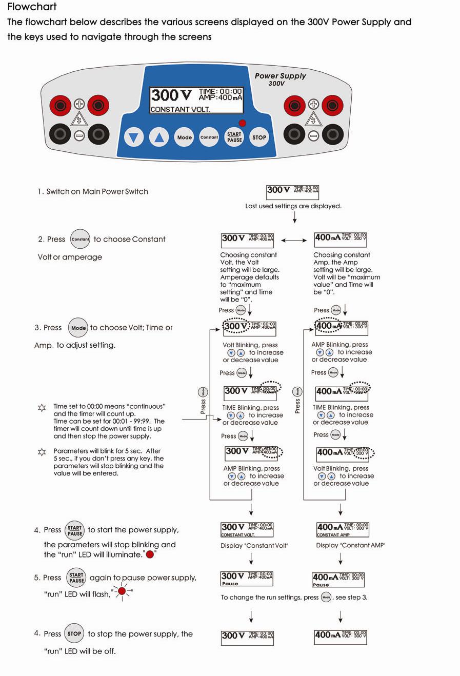
10 Basic Constant Operation Protocol The Constant Voltage and Constant Current Modes allow you to specify a voltage limit, and current limit to be used continuously during the entire duration of electrophoresis. Review the guidelines provided in this manual before starting electrophoresis. A basic Constant Voltage / Current Mode operating procedure of the 300Volt Power Supply is provided on the below. We recommend reading the guidelines provided in this manual for best results before starting an operation. 1. Use the power switch on the rear side of the instrument to turn on the 300V Power Supply. The Display Screen will illuminate. 2. Press the CONSTANT key to select either Constant Voltage Operation or Constant Current Operation from the Display Screen. 3. Use the Up Arrow / Down Arrow keys to set either voltage (V) or current (ma) parameters to the appropriate values. 4. Press the MODE key to choose the TIME parameter, and use the Up Arrow / Down Arrow keys to set the duration (hours/minutes) of the electrophoresis run. 5. Press START/PAUSE key to start electrophoresis. 6. Press the START/PAUSE key again to temporarily interrupt power. The red Run LED will flash to indicate that the electrophoresis run is paused. Pressing the START/PAUSE key again will restart the electrophoresis run. 7. Press the STOP key to permanently stop the electrophoresis run (the timer will reset). 8. To change the limits (Voltage or Amperage) of the electrophoresis run in progress: Press the Mode key. Enter the changes using the Up Arrow / Down Arrow keys, and then press START/PAUSE key once again to restart your operation. Note: After stopping (using the STOP key) and restarting an operation, the timer resets and does not take into account the time that electrophoresis was in progress before it was stopped.
11 Troubleshooting Review the information in the table below to troubleshoot operating problems. Problem Cause Solution The LCD screen remains blank and the AC power cord is not connected Check AC power cord connections at both ends. Use the correct cords. fan does not run when The fuse has blown Replace the fuse the power is turned on Operation stops with alarm: The screen displays NO LOAD Operation stops with alarm: Display shows OVER VOLTAGE Operation stops with alarm: Display shows LEAKAGE Operation stops with alarm: Display shows OVER TEMP Electrophoresis leads are not connected to the power supply or to the electrophoresis unit(s), or there is a broken circuit in the electrophoresis cell High resistance due to tape left on a pre-cast gel, incorrect buffer concentration, or incorrect buffer volumes in the electrophoresis cell High voltage application is set to run on a very low current Circuit is interrupted Ground leak detected during run Power supply is overheating Check the connections to the power supply and on your electrophoresis cell to make sure the connection is intact; check condition of wires in electrophoresis unit. Close the circuit by reconnecting the cables. Press START/PAUSE to restart the run. Correct the condition by making sure the tape is removed from the pre-cast gel, buffers are prepared correctly, and the recommended volume of buffer is added to the electrophoresis unit. DISABLE No Load alarm on the Display Screen Verify that the running buffer is correct. Verify the all cables are attached correctly Turn the Power switch off and on again; restart application. If you cannot restart the instrument, turn off the power, disconnect the power cord from the outlet, and contact Technical Service. Check the electrophoresis system for improper grounding. Restart the power supply by turning the Power switch off and on. Turn off power supply. Check for sufficient airflow around the power supply fan. After cooling down, restart the power supply by turning the Power switch to the on position. If you cannot restart the instrument, turn off the power, disconnect the power cord from the outlet, and contact Technical Service.

12 Repair and Maintenance of 300V Power Supply The ENDURO 300 Volt Power Supply requires no periodic maintenance program with the exception of an occasional dry wipe-down of the instrument. Encountering Problems 1. Check the troubleshooting section. 2. Contact Labnet s Technical Service Department. Their contact information in your area can be found at 3. If the unit must be shipped back for repair, contact your distributor for a Return Authorization Number and shipping instructions. The unit will be repaired as quickly as possible and returned to you. Replacing the Fuse One extra fuse is supplied with the 300Volt Power Supply. For additional fuses, contact Labnet s Technical Service department. To replace the fuse: 1. Turn off the main power switch at the rear of the 300V Power Supply and detach the power cord. 2. Open the fuse compartment located inside the Power Entry Module by inserting a small flat blade screwdriver into the slot below the ON/OFF switch. Turn the screwdriver to gently pry open the fuse compartment. Note: The fuse compartment will not open with the power cord in place. 3. Pull the fuse holder out of the compartment and inspect the fuse. If the fuse is burned or there is a break in the fuse element, replace the fuse with an identical type of fuse (4A/250V) as provided in the fuse holder (see figure below). 4. Place the fuse holder back into the compartment. 5. Snap the cover closed.
13 APPENDIX - Common Errors found with Electrophoresis Power Supplies No load The electrophoresis system is not connected to the power leads, check the power leads The electrophoresis system has a short, the Pt wire is broken or the banana connectors are damaged Buffer concentration too low Buffer volume too low Short in power cord Current has dropped below acceptable rating (4 ma) Short circuit Load exceeds 500 ma Blown fuse in the power supply Incorrect input voltage (check input voltage switch near power inlet) Change in load Electrophoresis systems were added or removed during a run Buffer leaking in a connected system Excessive temperature increase Excessive buffer evaporation Loose connection in a connected system Amperage set to low Change in constant mode Voltage changes to amperage 1. Amperage set too low. Ceiling hit and constant mode changed from voltage to amperage. Increase amperage to 500 ma. Amperage changes to voltage 1. Voltage set too low. Ceiling hit and constant mode changed from amperage to voltage. Increase voltage to 300 volts The 300 volt system has automatic cross over, set voltage or amperage, and preset wattage. During the electrophoresis process only one parameter is limiting at a time. The limiting parameter, together with the conductivity in the electrophoresis system, and the values for the other parameters determine the maximum output.
14 Ohm s Law Conversions Electrophoresis is the migration of a charged particle under the influence of an electrical field. The power supply output parameters voltage, current, and power are related by the following two equations: Voltage (V) = Current (I) x Resistance (R); (V=IR) Power (W) = Current (I) x Voltage (V); (W=IV) Resistance Resistance of the assembled electrophoresis cell is dependent on the conductivity of the gel buffer, the thickness of the gel, and the number of gels being run. Although the resistance is determined by the gel system, the resistance can vary over the course of an electrophoretic separation. Voltage The velocity with which an ion moves in an electric field will vary in proportion to the field strength (volts per unit distance). The higher the voltage the faster an ion will move. Current Current is a function of the number of ions passing a given cross-section of the circuit at a given time. For a given gel/buffer system, at a given temperature, current will vary in proportion to the field strength (voltage) and/or cross-sectional area (number and/or thickness of the gels). Power The power in Watts, or the rate of heat generated by the system, is directly proportional to voltage and current (W=IV).
15
16 Technical Service Web Resources Visit the Labnet s website at for: Complete technical service contact information. Access to Labnet s Online Catalog, and information about accessories and related products. Additional product information and special offers. Contact Us For information or technical assistance contact your local Labnet Dealer or visit. Legal Address of Manufacturer United States Europe Labnet International Labnet International 31 Mayfield Ave 31 Mayfield Ave Edison, NJ Edison, NJ Warranty Labnet International, Inc. warrants that this product will be free from defects in material and workmanship for a period of three (3) years from date of purchase. If a defect is present, Labnet International will, at its option, repair, replace, or refund the purchase price of this product at no charge to you, provided it is returned during the warranty period. This warranty does not apply if the product has been damaged by accident, abuse, misuse, or misapplication, or from ordinary wear and tear. For your protection, items being returned must be insured against possible damage or loss. This warranty shall be limited to the replacement of defective products. IT IS EXPRESSLY AGREED THAT THIS WARRANTY WILL BE IN LIEU OF ALL WARRANTIES OF FITNESS AND IN LIEU OF THE WARRANTY OF MERCHANTABILITY. For research use only. Not intended for any animal or human therapeutic or diagnostic use.

17 Equipment disposal This equipment is marked with the crossed out wheeled bin symbol to indicate that this equipment must not be disposed of with unsorted waste. Instead it's your responsibility to correctly dispose of your equipment at lifecycle -end by handling it over to an authorized facility for separate collection and recycling. It's also your responsibility to decontaminate the equipment in case of biological, chemical and/or radiological contamination, so as to protect from health hazards the persons involved in the disposal and recycling of the equipment. For more information about where you can drop off your waste of equipment, please contact your local dealer from whom you originally purchased this equipment. By doing so, you will help to conserve natural and environmental resources and you will ensure that your equipment is recycled in a manner that protects human health. Thank you
BT403. A Geno Technology, Inc. (USA) brand name. BT-300 Power Supply. Cat. No. BT
 brand name. BT-300 Power Supply. Cat. No. BT") BT403 A Geno Technology, Inc. (USA) brand name BT-300 Power Supply Cat. No. BT403 1-800-628-7730 1-314-991-6034 info@btlabsystems.com WARNING... 3 SAFETY INFORMATION... 3 ENVIRONMENTAL CONDITIONS... 4
BT403 A Geno Technology, Inc. (USA) brand name BT-300 Power Supply Cat. No. BT403 1-800-628-7730 1-314-991-6034 info@btlabsystems.com WARNING... 3 SAFETY INFORMATION... 3 ENVIRONMENTAL CONDITIONS... 4
NANOPAC-300 & 500 Power Supply. Instruction manual NANOPAC-300 & NANOPAC-500
 NANOPAC-300 & 500 Power Supply Instruction manual NANOPAC-300 & NANOPAC-500 Version 01C Feb 5th, 2014 1 Packing list NANOPAC-300 or 500-1x NANOPAC-300 Power Supply or NANOPAC-500-1x Power Cord - 1x Instruction
Cooling Module. Instruction Manual
 Cooling Module Instruction Manual Catalog Numbers 170-3654, 170-3655, and 170-3688 For Technical Service Call Your Local Bio-Rad Office or in the U.S. Call 1-800-4BIORAD (1-800-424-6723) Warranty Bio-Rad
Clinispin CT20 User Manual
 Clinispin CT20 User Manual C0060-WOD-230EU Lit M00031 Rev 1 June, 2012 Safety Precautions NEVER NEVER NEVER NEVER NEVER NEVER NEVER NEVER ALWAYS ALWAYS ALWAYS ALWAYS use the centrifuge in any manner not
BroadBand PowerShield. 20 AHr Battery. User Manual
 BroadBand PowerShield 20 AHr Battery User Manual 990-1316A 10/2004 Chapter 1 General Information The PowerShield provides a power source for broadband telephony applications. Important Safety Instructions
Installation/Operating Instructions
 Installation/Operating Instructions LEC 315 COMMERCIAL ETELLIGENT INCLUDES CONVERTIBLE SMART VOLT DUAL FERRITE POWER CORD easily converts into either a 120 or 208/240 volt 6.5 foot power cord ETELLIGENT
Installation/Operating Instructions
 1000 DE BOSS COMMERCIAL FIXTURE Installation/Operating Instructions 600W 750W 1000W Turbo 825W 1000W 1150W 750W INPUT RC 660W SIG A 600W SIG B www.sunlightsupply.com INCLUDES CONVERTIBLE SMART VOLT DUAL
Cruising Charger Series OWNER S MANUAL
 R Cruising Charger Series OWNER S MANUAL ON BOARD BATTERY CHARGERS Models DC Amperage No. Of Banks Volts 2614A 5,10 Amps 2 Bank 12/12 2614A-230 2621A 5,5,10 Amps 3 Banks 12/12/12 2621A-230 2622A 10,10
Mazda New CX-5 TPMS Pressure by Location Display TABLE OF CONTENTS TIRE PRESSURE MONITORING SYSTEMS, TPMS... 2
 Mazda New CX-5 TPMS Pressure by Location Display TABLE OF CONTENTS TIRE PRESSURE MONITORING SYSTEMS, TPMS... 2 NOTICE... 2 SPECIFICATIONS OF TPMS... 4 ACCESSORIES... 4 DISPLAY UNIT INSTALLATION... 5 SYSTEM
AC / 65 W M PLEASE READ BEFORE OPERATING THIS EQUIPMENT.
 AC / 65 W M 5V AX 11 PLEASE READ BEFORE OPERATING THIS EQUIPMENT. TABLE OF CONTENTS 1 2-10 6-8 11 11 12 14-15 AC / 65 W M 5V AX 11 Included Items Operating Instructions Troubleshooting Guide Maintenance
Z100A Clinical Centrifuge
 Z100A Clinical Centrifuge User Manual C0100-A Rev 2 August 2016 About This Manual This manual is designed to assist you in the optimal usage of your Labnet Z100A Clinical Centrifuge. The manual is available
Metrohm E3640 FLASH TESTER INSTRUCTION MANUAL. Martindale Electric Co Ltd.
 Metrohm Martindale Electric Metrohm House, Imperial Park, Imperial Way, Watford, Hertfordshire, WD24 4PP, UK T: 01923 441717 F: 01923 446900 Email: sales@martindale-electric.co.uk web: www.martindale-electric.co.uk
Valor 1000W Series Instruction Manual. Serie Valor 1000W Manual de Instrucciones. Série Valor 1000W Guide de I utilisateur
 Valor 1000W Series Instruction Manual Serie Valor 1000W Manual de Instrucciones Série Valor 1000W Guide de I utilisateur Serie Valor 1000W Bedienungsanleitung Serie Valor 1000W Manuale d instruzioni OHAUS
Filtered PWM Speed Control for Permanent Magnet DC Motors
 Instructions for Installation and Operation Filtered PWM Speed Control for Permanent Magnet DC Motors Model 0794 Speed and Direction Control up to 5/8 HP NEMA-1/IP-20 Specifications Product Type:... WPM-2148E1
Operator Manual For use with WFCO ULTRA III Deckmount Converter WF-9800 Series (model number located on the cover of the unit)
") Operator Manual For use with WFCO ULTRA III Deckmount Converter WF-9800 Series (model number located on the cover of the unit) Distributed in the U.S.A. and Canada by ARTERRA DISTRIBUTION Warranty Service
Operator Manual For use with WFCO ULTRA III Deckmount Converter WF-9800 Series (model number located on the cover of the unit) Distributed in the U.S.A. and Canada by ARTERRA DISTRIBUTION Warranty Service
1000-Watt Energy Center
 1000-Watt Energy Center OPERATING INSTRUCTIONS Patent Pending Sierra Wave 1000-Watt Energy Center #9675 The Sierra Wave 1000-Watt Energy Center is a heavy duty and efficient portable power center offering
PL900 ILLUMINATOR. Fiber-Lite. Operation Manual. Setup. Fiber Optic Connection A PRODUCT OF DOLAN-JENNER INDUSTRIES. Voltage Selection:
 PL900 ILLUMINATOR A PRODUCT OF DOLAN-JENNER INDUSTRIES Setup Voltage Selection: Operation Manual Read and review the instructions on the label covering the power entry module and the instructions in this
1000 DE BOSS. Installation & Operating Instructions COMMERCIAL FIXTURE READ THESE INSTRUCTIONS BEFORE FIRING UP YOUR BALLAST
 RC ETELLIGENT CONTROLLER compatible Sun System 1 Ballasts are controller-compatible with signal ports for on /off /dimming functions (Etelligent controller sold separately. Part # 902245 ) 1000 DE BOSS
VP-4124/VP-4124-E 24/48 VOLT DC SWITCHING POWER SUPPLY
 Issue 5 24/48 VOLT DC SWITCHING POWER SUPPLY INTRODUCTION These instructions provide the specifications, installation and maintenance information for the VP-4124 and VP-4124-E, 24/48 Volt Power Supplies.
To ensure correct operation and service please read these instructions before installing and operating the TPMS P451 TPMS Manual TABLE OF CONTENTS
 To ensure correct operation and service please read these instructions before installing and operating the TPMS P451 TPMS Manual TABLE OF CONTENTS TIRE PRESSURE MONITORING SYSTEMS, TPMS... 2 NOTICE...
A419ABG-3C Electronic Temperature Control
 Installation Instructions Issue Date June 16, 2003 A419ABG-3C Electronic Temperature Control Application IMPORTANT: Use this A419ABG-3C Electronic Temperature Control only as an operating control. Where
OPERATING INSTRUCTIONS
 OPERATING INSTRUCTIONS HALO BOLT 57720 Powerful, compact and easy to use, the HALO BOLT can safely jump start your car. In addition, you can use it to charge your phone, tablet or other electronic devices!
SPECTRAFUGE 6C. User Manual C0060 C V
 SPECTRAFUGE 6C User Manual C0060 C0060-230V Lit M00031 Rev 2 August 2016 About This Manual This manual is designed to assist you in the optimal usage of your Labnet Spectrafuge 6C Centrifuge. The manual
Solar Hybrid Power Generating System CPS1200EOH12SC CPS2200EOH24SC CPS3000EOH24SC. User s Manual K01-C
 Solar Hybrid Power Generating System CPS1200EOH12SC CPS2200EOH24SC CPS3000EOH24SC User s Manual K01-C000304-02 2 TABLE OF CONTENTS 1 IMPORTANT SAFETY INSTRUCTIONS..4 2 INSTALLATION....5 2-1 Unpacking...5
5-Piece Grill Tool Set WITH DIGITAL THERMOMETER
 5-Piece Grill Tool Set WITH DIGITAL THERMOMETER TABLE OF CONTENTS Warnings and Cautions...1 Location of Fork Parts and Controls.... 3 Installing the Battery in the Fork... 3 Using the Thermometer.... 4
Operators Manual. Recirculating Chiller /06/08
 Operators Manual Recirculating Chiller 110-197 11/06/08 Table of Contents Section 1. General Information 1.1 Warranty 1.2 Unpacking 1.3 Package Contents 1.4 Description of the Recirculating Chiller 1.5
Prism Microcentrifuge
 Prism Microcentrifuge User Manual C2400 C2400-100V C2400-230V C2500 C2500-100V C2500-230V Lit M00029 Rev 2 December 2012 Safety Precautions NEVER use the centrifuge in any manner not specified in these
Compact Scales. Software Revision V1.25 & above
 Compact Scales Software Revision V1.25 & above 2016 1 Easy Reference: Model name of the scale: Serial number of the unit: Software revision number (Displayed when power is first turned on): Date of Purchase:
Combined Ventilation Controller RVWS-T-224HA
 Combined Ventilation Controller RVWS-T-224HA 8-stage Control for Power/Natural Applications 2 variable speed stages, 2 curtain winch stages, 2 fixed speed ventilation stages, 1 thermo/mister cycle stage
Video & Power Over Coax Kit
 VPoC User Manual Video & Power Over Coax Kit 1CH Video Power over Coax w/ 12V DC Receiver Device VPoC24DC-01K VPoC24DC-01 N-42-1 x1 N-41C 4CH / 8CH / 16CH Video Power over Coax Server Kit VPoC24DC-04K
FastPrep FP120 Cell Disrupter INSTRUCTION MANUAL
 FastPrep FP120 Cell Disrupter INSTRUCTION MANUAL Applies to FP100, FP120, and FP220 Models Qbiogene, Inc. (North America) 2251 Rutherford Road Carlsbad, CA 92008 Phone (800) 424-6101 Fax (760) 918-9313
MODEL 2602A-12 3 STAGE AUTOMATIC BATTERY CHARGER OWNER S MANUAL SAVE THESE INSTRUCTIONS
 R A Valley Forge Company MODEL 2602A-12 3 STAGE AUTOMATIC BATTERY CHARGER OWNER S MANUAL SAVE THESE INSTRUCTIONS 1. INTRODUCING THE CHARGER The 2602A-12 is a 3-stage electronic battery charger. Rainproof,
VP-6124/VP-6124-E 24 VOLT DC SWITCHING POWER SUPPLY
 Issue 6 VP-6124/VP-6124-E 24 VOLT DC SWITCHING POWER SUPPLY INTRODUCTION These instructions provide the specifications, installation and maintenance information for the VP-6124 and VP-6124-E, 24Volt Power
Operator's Manual. Storage System. Ultrasound Probe Cabinet. Manufactured by:
 Storage System Ultrasound Probe Cabinet Operator's Manual Manufactured by: CIVCO Medical Solutions 102 First Street South Kalona, IA 52247 USA 319.248.6757 / 800.445.6741 WWW.CIVCO.COM Copyright 2018 All
Safety, Installation and Service Manual Models 1952, 1953 & 1972
 Ultraviolet Germicidal Lamps Model 1952 24 Rooftop Unit Model 1953 32 Rooftop Unit Model 1972 Rooftop Unit, Internal Mount Safety, Installation and Service Manual Models 1952, 1953 & 1972 READ AND SAVE
SOS SERIES SOS1 SOS2. Spares On Site Battery Cabinet Installation Guide rEV3
 Atlantic Battery Systems 1065 Market Street Paterson, NJ 07513 Phone: (800) 875-0073 Fax: (973) 523-2344 sales@atbatsys.com www.atbatsys.com SOS1 SOS2 SOS SERIES Spares On Site Battery Cabinet Installation
2800 OPERATING INSTRUCTIONS
 StarLight 2800 OPERATING INSTRUCTIONS 3 4 2 5 1 1. Input port: 5V/1000mA 2. Output port: 5V/1000mA 3. Power Switch 4. Indicator display 5. Flashlight Included items: -HALO StarLight 2800 charger unit -1
A419 Series Electronic Temperature Controls with NEMA 1 or NEMA 4X Watertight Enclosures
 Installation Instructions Issue Date April 8, 2008 A419 Series Electronic Temperature Controls with NEMA 1 or NEMA 4X Watertight Enclosures Application IMPORTANT: The A419 Series Electronic Temperature
SFA275 USER MANUAL PLEASE READ THIS USER MANUAL COMPLETELY BEFORE OPERATING THIS UNIT AND RETAIN THIS BOOKLET FOR FUTURE REFERENCE
 Parking Alert Sensor SFA275 USER MANUAL PLEASE READ THIS USER MANUAL COMPLETELY BEFORE OPERATING THIS UNIT AND RETAIN THIS BOOKLET FOR FUTURE REFERENCE COMPLIANCE WITH FCC REGULATIONS This device complies
Operator Manual For use with WFCO ULTRA III Power Center Model WF-8712P and WF-8725P
 Operator Manual For use with WFCO ULTRA III Power Center Model WF-8712P and WF-8725P Distributed in the U.S.A. and Canada by Arterra Distribution Sales (574) 294-8997 Warranty Service (877) 294-8997 Fax
12 Volt Heavy-Duty Air Inflator
 12 Volt Heavy-Duty Air Inflator Owner s Manual WARNING: Read carefully and understand all ASSEMBLY AND OPERATION INSTRUCTIONS before operating. Failure to follow the safety rules and other basic safety
O W N E R ' S M A N U A L
 1500 Watt DC to AC Power Inverter C o n v e r t s 1 2 V D C B a t t e r y P o w e r t o 1 1 0 V A C H o m e P o w e r O W N E R ' S M A N U A L SAVE THESE INSTRUCTIONS The recommended source of power is
Temperature Controller. TC5+2V4SA Plus USER'S MANUAL
 Temperature Controller TC5+2V4SA Plus USER'S MANUAL NOTICE Every effort has been made to ensure that this manual is complete, accurate and up-to-date. The information contained in it is however subject
Thermometer models / 00831A
 Instruction Manual Thermometer models 00822 / 00831A CONTENTS Unpacking Instructions... 2 Package Contents... 2 Product Registration... 2 Features & Benefits... 3 Setup... 4 Install or Replace Batteries...
Safety Precaution. Notation. Meaning of symbols WARNING CAUTION
 Safety Precaution Introduction The following precautions are provided for using the Mobile Terminal safely. The symbols used and their meanings are described below. Make sure you have understood the safety
Owner's Manual. For latest instructions please go to
 mycharge name and logo are registered trademarks of RFA Brands. 2012-2013 RFA Brands. All Rights Reserved. Patent Pending. Made in China. IB-MYC0600 Owner's Manual For latest instructions please go to
Product Overview. Product Identification. Amps One CT Two CTs Three CTs
 AH06 (optional mounting bracket for small, medium, and large CTs) DANGER HAZARD OF ELECTRIC SHOCK, EXPLOSION, OR ARC FLASH Follow safe electrical work practices. See NFPA 70E in the USA, or applicable
Paraffin Dispenser Catalog # PD-120, PD-220 Operator s Manual Version 1.5b, Jan 2007
 Paraffin Dispenser Catalog # PD-120, PD-220 Operator s Manual Version 1.5b, Jan 2007 Be certain to read this manual thoroughly before proceeding with unpacking and installation. TABLE OF CONTENTS Topic
1000 Watt Power Inverter INSTRUCTION MANUAL HT87112-AUOXY
 1000 Watt Power Inverter INSTRUCTION MANUAL HT87112-AUOXY CONTENTS Warranty 2 Introduction 3 Environmental protection 3 Specifications 3 General safety warnings and instructions 4 Important safety instructions
翔鑫科技股份有限公司. Oro Technology Co., LTD. 無線胎壓監測器 Tire Pressure Monitoring System 型號 : W410
 翔鑫科技股份有限公司 Oro Technology Co., LTD 無線胎壓監測器 Tire Pressure Monitoring System 型號 : W410 ORO TPMS User Manual To ensure correct operations and services please read these instructions before installing and
The Efficient Solution for Pipetting up to 100 ml at once! USER'S GUIDE
 The Efficient Solution for Pipetting up to 100 ml at once! This equipment generates, uses and can radiate radio frequency energy and, if not installed and used in accordance with the User s Guide, may
Portable Sanitizing Wand. Model: VH03. The CleanWave Portable Sanitizing Wand kills up to 99.9% of germs and odorcausing. surfaces.
 The CleanWave Portable Sanitizing Wand kills up to 99.9% of germs and odorcausing bacteria on hard surfaces. To Start, Press Until Beep Portable Sanitizing Wand SAVE THESE INSTRUCTIONS Model: VH03 Edit
Owners Manual for TPMS plus GPS
 To ensure correct operation and service please read these instructions before installing and operating the TPMS feature of the TPMS/GPS unit. Owners Manual for TPMS plus GPS TABLE OF CONTENTS TIRE PRESSURE
SAVE THESE INSTRUCTIONS
 12 Volt High-V Volume Air Inflator Owner s Manual WARNING: Read carefully and understand all ASSEMBLY AND A OPERATION INSTRUCTIONS before operating. Failure to follow the safety rules and other basic safety
Power Inverter. User s Manual. Diamond Series CPD1200EILCD
 Power Inverter Diamond Series CPD1200EILCD User s Manual 2 TABLE OF CONTENTS 1 IMPORTANT SAFETY INSTRUCTIONS..4 2 INSTALLATION....5 2-1 Unpacking...5 2-2 Product Overview & Outlook..5 2-3 Power Requirements
Owner's Manual. mycharge name and logo are registered trademarks of RFA Brands RFA Brands. All Rights Reserved. Patent Pending.
 REGISTER Your Product At: www.mycharge.com Your valuable input regarding this product will help us create the products you will want in the future. PLEASE TAKE A MOMENT NOW mycharge name and logo are registered
3000VA 120/208/230VAC
 User s Manual English Smart-UPS 2200VA 120/230VAC 3000VA 120/208/230VAC 2U Rack Mount Uninterruptible Power Supply 990-1352 12/02 Introduction The APC Uninterruptible Power Supply (UPS) is designed to
Nature Power Inverters. True Sinewave Inverter Modified Sinewave Inverter. Owner s Manual
 Version 1.1 Version 2 Nature Power Inverters True Sinewave Inverter Modified Sinewave Inverter Owner s Manual!!!!!!!!!!! 38304 38204 For safe and optimum performance, the Power Inverter must be used properly.
Owner s Guide. ca5354
 PROFESSIONAL SERIES Owner s Guide for models: ca5354 Deluxe Vehicle Remote Start System with 900Mhz 2 Way Confirming LED Remote Control IMPORTANT NOTE: The operation of the Security and Convenience System
LIGHT & SOUND BATH VANITY LIGHT
 LIGHT & SOUND ATH VANITY LIGHT CONTEMPORARY SLAT 3L SWITCH/NL/T LACK CHROME ITM. / ART. 962793 Model #: 1301-030303-01 ASSEMLY, INSTALLATION, AND CARE INSTRUCTIONS IMPORTANT, RETAIN FOR FUTURE REFERENCE
MRC 150/300 USER MANUAL. 1 Laird Technologies
 MRC 150/300 USER MANUAL 1 www.lairdtech.com Laird Technologies THR-UM-MRC150-300 0912 Americas: +1 888.246.9050 Europe: +44.1342.315044 Asia: +886.3.312.9292 clv.customerpos@lairdtech.com 2 www.lairdtech.com
User Manual. T6 Tachometer. Online: Telephone: P.O. Box St. Petersburg, Florida 33736
 User Manual T6 Tachometer Online: www.phareselectronics.com Telephone: 727-623-0894 P.O. Box 67251 St. Petersburg, Florida 33736 Table of Contents Overview... 1 Description... 1 Wiring... 1 T6 Tachometer
NCSA 20plus Service Manual
 Adam Equipment NCSA 20plus Service Manual (P.N. 7.00.6.6.0247- Revision A - August 2012) Adam Equipment Company 2012 1.0 CONTENTS 1.0 CONTENTS...1 1.1 KEY AND PANEL DESCRIPTION...2 2.0 OPERATION...3 2.1
WARNINGS, CAUTIONS AND NOTES
 Welcome Please read this manual thoroughly before installing and operating your new Power Bright Power Inverter. This manual contains information you need to obtain the performance required for your application.
To ensure correct operation and service please read these instructions before installing and operating the TPMS. TPMS Manual
 To ensure correct operation and service please read these instructions before installing and operating the TPMS TPMS Manual TABLE OF CONTENTS TIRE PRESSURE MONITORING SYSTEMS, TPMS... 2 NOTICE... 2 SPECIFICATIONS
Triple Output High Resolution Power Supply. User Manual
 1320 Triple Output High Resolution Power Supply User Manual Safety Summary The following safety precautions apply to both operating and maintenance personnel and must be observed during all phases of operation,
User Guide. Model No.: GDI-GFD7200
 User Guide Model No.: GDI-GFD7200 2 Important Safety Instructions and Warnings Please read before installation WARNING: CAUTION: To reduce the risk of fire or electrical shock, do not expose the product
Adam Equipment LHS SERIES. (P.N , Revision A March 2012)
") Adam Equipment LHS SERIES (P.N. 7.00.6.6.0200, Revision A March 2012) Adam Equipment Company 2012 1.0 CONTENTS 1.0 CONTENTS...1 2.0 INTRODUCTION...2 2.1 INTRODUCTION...2 2.2 TECHNICAL SPECIFICATIONS...3
Adam Equipment LHS SERIES (P.N. 7.00.6.6.0200, Revision A March 2012) Adam Equipment Company 2012 1.0 CONTENTS 1.0 CONTENTS...1 2.0 INTRODUCTION...2 2.1 INTRODUCTION...2 2.2 TECHNICAL SPECIFICATIONS...3
user manual Electrophoresis Systems, Standards and Reagents PS 500XT DC power supply PS500XT-IM/Rev C0/9-99
 user manual Electrophoresis Systems, Standards and Reagents DC power supply PS 500XT um 80-6306-67 PS500XT-IM/Rev C0/9-99 con ontents 1 Operating Instructions................................. 1 Constant
Owner s Guide CARS & CA4B5
 PROFESSIONAL SERIES Owner s Guide For Model: CARS & CA4B5 Deluxe Vehicle Remote Start and Keyless Entry System IMPORTANT NOTE: The operation of the Security and Convenience System as described in this
READ AND FOLLOW ALL SAFETY INSTRUCTIONS SAVE THESE INSTRUCTIONS
 7.5 Swift Lock Ready Shape Tree (Patent Pending) Instructions IMPORTANT SAFETY INSTRUCTIONS When using electrical products, basic precautions should always be followed including the following: READ AND
Product Name. Paraffin Dispenser. Operator s Manual. Histology Innovation for a NEW Generation PD-120; PD-220. A Division of General Data Healthcare
 A Division of General Data Healthcare Histology Innovation for a NEW Generation Pub No.: OM PD-1 June 2013, Version 1.8 PD-120; PD-220 Operator s Manual Product Name Here Catalog #s Paraffin Dispenser
OPERATING INSTRUCTIONS
 CM OPERATING INSTRUCTIONS 9 Function, Auto Range Digital Multi-Meter DM6450 INTERTEK Read this owner s manual thoroughly before use and save. C LISTED US I. DISPLAY FUNCTIONS & SYMBOLS 9 6 10 11 14 8 7
Remote Vehicle Control System. Keyless Entry & Remote Start System
 1 Remote Vehicle Control System PC 7400 TM Owner's Manual Keyless Entry & Remote Start System IMPORTANT NOTE: The operation of the Power Code as described in this manual is applicable to most vehicles.
AeraMax Pro AM IV. Please read these instructions before use. Do not discard: keep for future reference.
 AeraMax Pro AM IV Please read these instructions before use. Do not discard: keep for future reference. ENGLISH AeraMax PRO Air Quality Control System: AM IV SAFETY INSTRUCTIONS/WARNING Thank you for purchasing
Model G14SD Vapor Management System
 Instruction Manual Model G14SD Vapor Management System (For Models: DSD and SSD 110/115v) Manufactured in USA for Medivators Reprocessing Systems by: PCI Medical Inc. 12 Bridge Street, PO Box 188 Deep
Bio Lion Table Top Centrifuge XC-H165
 Bio Lion Table Top Centrifuge XC-H165 Operation Manual Table of contents Section Specification Page 1 Pictures Page 2-3 Starting Safety information Page 4 Set up Page 5-7 Operation Page 7-8 Troubleshooting
Conserve Insight Energy Use Monitor. User Guide
 Conserve Insight Energy Use Monitor User Guide Find out how much energy your devices really use including watts, the cost of operation, and the amount of carbon dioxide (CO 2 ) produced in generating the
Owner s Guide. ca5154
 PROFESSIONAL SERIES Owner s Guide for models: ca5154 Automatic / Manual Transmission Remote Start and Keyless Entry System IMPORTANT NOTE: The operation of the Security and Convenience System as described
CA 5054 Owner s Guide
 PROFESSIONAL SERIES CA 5054 Owner s Guide Remote Start and Keyless Entry System IMPORTANT NOTE: The operation of the Security and Convenience System as described in this manual is applicable to most vehicles.
Adam Equipment DUNE DCT SERIES. (P.N. 9384, Revision B2, June 2013)
") Adam Equipment DUNE DCT SERIES (P.N. 9384, Revision B2, June 2013) Adam Equipment Company 2013 Easy Reference: Model name of the scale: Serial number of the unit: Software revision number (Displayed when
Adam Equipment DUNE DCT SERIES (P.N. 9384, Revision B2, June 2013) Adam Equipment Company 2013 Easy Reference: Model name of the scale: Serial number of the unit: Software revision number (Displayed when
Remote Vehicle Control System. Keyless Entry and Convenience System
 1 Remote Vehicle Control System PC 6100 TM Owner's Manual Keyless Entry and Convenience System IMPORTANT NOTE: The operation of the Power Code as described in this manual is applicable to most vehicles.
Owner s Guide CA 5055
 PROFESSIONAL SERIES Owner s Guide For Model: CA 5055 Vehicle Remote Start and Keyless Entry System IMPORTANT NOTE: The operation of the Security and Convenience System as described in this manual is applicable
User Manual. Solar Charge Controller 3KW
 User Manual Solar Charge Controller 3KW 1 CONTENTS 1 ABOUT THIS MANUAL... 3 1.1 Purpose... 3 1.2 Scope... 3 1.3 SAFETY INSTRUCTIONS... 3 2 INTRODUCTION... 4 2.1 Features... 4 2.2 Product Overview... 5
User Manual Solar Charge Controller 3KW
 User Manual Solar Charge Controller 3KW Version: 1.3 CONTENTS 1 ABOUT THIS MANUAL... 1 1.1 Purpose... 1 1.2 Scope... 1 1.3 SAFETY INSTRUCTIONS... 1 2 INTRODUCTION... 2 2.1 Features... 2 2.2 Product Overview...
Owner's Manual. For latest instructions please go to
 mycharge name and logo are registered trademarks of RFA Brands. 2012-2013 RFA Brands. All Rights Reserved. Patent Pending. Made in China. IB-RFAM0237 Owner's Manual For latest instructions please go to
Operating Instructions
 Operating Instructions Contents Introduction 1 Operating Instructions 2-7 Storing/Handling/Cleaning 7 Safety Precautions 7-8 Specifications 9 FCC Compliance Statement 9-10 Limited Warranty 10-11 Contact
Installation Guide Smart-UPS On-Line SRT1000/SRT1500 XLA Tower/Rack-Mount
 Installation Guide Smart-UPS On-Line SRT1000/SRT1500 XLA Tower/Rack-Mount Important Safety Messages Read the instructions carefully to become familiar with the equipment before attempting to install, operate,
GRUNDFOS INSTRUCTIONS. Grundfos ALPHA Installation and operating instructions
 GRUNDFOS INSTRUCTIONS Grundfos ALPHA Installation and operating instructions LIMITED WARRANTY Products manufactured by GRUNDFOS PUMPS CORPORATION (Grundfos) are warranted to the original user only to be
Model Battery Powered Milliohm Meter
 User s Guide Model 380580 Battery Powered Milliohm Meter Introduction Congratulations on your purchase of Extech s Model 380580 Battery Powered Milliohm Meter. This device offers five resistance ranges
Operator Manual For use with WFCO ULTRA III Distribution Center WF-8900 Series (model number located on the door assembly label)
") Operator Manual For use with WFCO ULTRA III Distribution Center WF-8900 Series (model number located on the door assembly label) Distributed in the U.S.A. and Canada by ARTERRA DISTRIBUTION Warranty Service
Operator Manual For use with WFCO ULTRA III Distribution Center WF-8900 Series (model number located on the door assembly label) Distributed in the U.S.A. and Canada by ARTERRA DISTRIBUTION Warranty Service
Design Features: User Manual. 1. PFC function. 2. LCD remote control. 3. Battery temperature sensor function.
 User Manual Design Features: 1. PFC function. except BC-1215HT / BC-2407HT 2. LCD remote control. BC-1215HT / BC-2407HT 3. Battery temperature sensor function. 4. Tri-LED color indicator for different
MODUL-CONNECT 1.2. Owner s Manual. Modular, digital wiring and control system. Document Part Number MSMC Rev 9 (04/18)
") MODUL-CONNECT 1.2 Modular, digital wiring and control system Owner s Manual Document Part Number MSMC Rev 9 (04/18) Service Contact Information E-mail: info@modul-system.com Phone: +46 31 746 87 00 Web:
MODUL-CONNECT 1.2 Modular, digital wiring and control system Owner s Manual Document Part Number MSMC Rev 9 (04/18) Service Contact Information E-mail: info@modul-system.com Phone: +46 31 746 87 00 Web:
Spectrafuge 24DMicrocentrifuge User Manual C2400 C V C V
 Spectrafuge 24DMicrocentrifuge User Manual C2400 C2400-100V C2400-230V Lit M00013 Rev 3 August 2016 About This Manual This manual is designed to assist you in the optimal usage of your Labnet 24D Microcentrifuge.
Patient Lift Scale Indicator Owner s Manual
 Patient Lift Scale Indicator Owner s Manual Item # 13046 INTRODUCTION Thank you for purchasing the Model PL600DM Patient Lift Scale Indicator. It has been manufactured with quality and reliability. This
Power Inverter 400 MW Owner s Manual
 Power Inverter 400 MW 1204 Owner s Manual For safe and optimum performance, the Power Inverter must be used properly. Carefully read and follow all instructions and guidelines in this manual and give special
READ AND FOLLOW ALL SAFETY INSTRUCTIONS SAVE THESE INSTRUCTIONS
 5 Swift Lock Ready Shape Tree (Patent Pending) Instructions IMPORTANT SAFETY INSTRUCTIONS When using electrical products, basic precautions should always be followed including the following: READ AND FOLLOW
110 Volt/12 Volt Portable Inflator
 110 Volt/12 Volt Portable Inflator Owner s Manual WARNING: Read carefully and understand all ASSEMBLY AND OPERATION INSTRUCTIONS before operating. Failure to follow the safety rules and other basic safety
i n s t r u c t i o n m a n u a l
 i n s t r u c t i o n m a n u a l 8006 Six-Station AC Timer Residential/Light Commercial Independent Program Irrigation Controllers Installation, Programming and Operating Instructions Features Operates
P Volt Charger Each sold separately and subject to availability.
 P6828 6-Volt 4 Amp/Hr Battery P6829 6-Volt Charger Each sold separately and subject to availability. IMPORTANT SAFETY INSTRUCTIONS - SAVE THESE INSTRUCTIONS. For use with a Power Wheels toddler vehicle