NO SINGLE STAGE PROGRESSIVE, TPS, RPM WINDOW SWITCH
|
|
|
- Charla Sparks
- 6 years ago
- Views:
Transcription
 and integrated throttle-position activation switch (TPAS). The unit accepts most tach signals, including low-voltage and irregular signals such as those found on many V-10s.")
.")
1 NO SINGLE STAGE PROGRESSIVE, TPS, RPM WINDOW SWITCH Operation The Nitrous Outlet PROGRESSIVE/RPM WINDOW SWITCH is a single stage progressive controller with an RPM activated window switch (RPMWS) and integrated throttle-position activation switch (TPAS). The unit accepts most tach signals, including low-voltage and irregular signals such as those found on many V-10s. The TPAS accepts all analog throttle-position sensor signals as well as a hot or grounded wide-open-throttle (WOT) switch. This unit has settable ON/LOW and OFF/HI RPM points and a multi-gear lockout feature. Multi-gear lockout delays the stage from turning ON until you have cycled through the RPM window (X times). The internal TPAS can be configured to prevent the RPMWS channel from activating until you are at WOT. The Nitrous Outlet RPM WINDOW SWITCH requires 9~18 volts to operate correctly. NOTE: Output lines are rated for a maximum current of 1 amp and the progressive output is only for use with the high current driver. In run mode, the LEDs (A.B.C.) will show the unit s status. A = throttle position activation switch status [0 = OFF / 1 = ON] B = gear lock out [0 = feature OFF / L = locked out] C = rpm window status [ 0 = not in RPM range / 1 = in RPM range] Press and hold switch #2 and the unit will display the current RPM (AB.C). This will be very useful to verify your setting in STEP 1 of the configuration. Example: 12.5 = RPM. Programming the RPM Window Switch Switch #1 - toggles through the configuration menu. As you toggle through the configuration menu, the stored value will be displayed. Each time you push Switch #1 it will move the flashing character to the next digit. EXP. Space B will be flashing while making changes to this field (using switch 2), push switch 1 when you are ready to move to space C Each step is programmed the same way. Switch #2 - increments the flashing value that was selected by switch #1. Push Switch #2 to get the flashing character to the number you need for programming your application. EXP. Each time switch #2 is pushed the field that is flashing will increase by a value of 1. LED A.B C displays the configuration step number and its setting A: = configuration item. The Set up Number can be shown solid or a brief moment depending on configuration screen. A B C = value for the current configuration step
2 To enter the programming mode, press and hold both switches until Pro is displayed. Now release the switches and the unit will automatically go to the first configuration step. STEP 1. Progressive START % LED A is Step# LED B C is your Progressive START % = Starting ramp percentage is 10% = Starting ramp percentage is 25%. STEP 2. Progressive RAMP TIME. This is how much it will take to go from activation to 100% progressive power = Ramp time of 5 seconds = Ram; time of 1.4 seconds. STEP 3. Reset / Resume: This is useful for clutch cars. 3 0 = Progressive unit will reset the ramping to the beginning if WOT is cycled. 3 1 = Progressive unit will pick up where it left off ramping if WOT is cycled. STEP 4. Standard / Advanced Mode. This setting will allow you to stop your programming here and use the controller as a progressive unit only. OR continue programming for added features; RPM window switch, TPS mode, Gear lock out 4 0 = Standard Mode: Unit is being used as a progressive unit only. In this mode your BLUE wot input wire must be connected to a mechanical WOT switch. Using the STANDARD programming wiring digram. 4 1 = Advanced Mode: All the features are available in this mode. Including all WOT options. STEP 5. TACH set-up B C is the number of cylinders. This setting is used by the RPMWS to calculate the correct RPM = individual coil per cylinder systems where the tach wire is connected to the coil trigger wire = coil packs that fire in pairs (waste spark systems) where the tach wire is connected to the coil trigger wire ~ = cylinder combinations from 2 to 12 where the tach wire is connected to the tach signal from the engine electronic controller or distributor. EX. 002 would be for a 2 cylinder application. NOTE: LS1 vehicles connecting to the tach wire at the pcm will use 004, if connecting to a coil pack use 000.
3 STEP 6.. Gear Lockout A = not used at this time B = not shown. C = how many times you must pass the deactivation set point before the switch will activate. 0 turns this option off. EXAMPLES BELOW You will only see this screen with the right digit blinking. 6: 0 = NO gear lock out is selected. System will activate at the preset RPM window and TPS WOT settings. 6: 1 = You must pass your deactivation RPM 1 time, before that system will activate. 6: 4 = You must pass your deactivation RPM 4 times, before that system will activate. STEP 7. RPM set up for Channel 1 Activation. You will only see this screen for a brief moment. Activation RPM A B C = RPM where 02.3 = 2300 RPM. The digit you are adjusting will be blinking. Never set below STEP 8. RPM set up for Channel 1 Deactivation RPM You will only see this screen for a brief moment. Deactivation RPM A B C = RPM where 06.6 = 6600 RPM STEP 9. TPAS Mode A B C = throttle position activation switch mode = grounded WOT switch = hot WOT switch = TPS signal to PCM = turns this feature off if you are not connecting the blue wire. WARNING!!! This option should only be chosen IF you have a WOT device controlling the relay. Using this feature will activate the relay anytime the system is armed and inside the Activation and Deactivation window. Primarily used for systems that are already wired and want to have features of a window switch.
4 STEP 10. TPS WOT setting Note: only applies if Step 5 is configured as 002 9:B.C = WOT voltage While at IDLE, press switch #2 to read and display the TPS signal. Pop the throttle to open it all the way the unit only needs to see WOT for a fraction of a second. Now press switch #1 to save the displayed value. (You do not have to be at WOT when you press switch #1 to save) Drive By Wire cars should go for a test drive for step 9. Since the throttle blade may have some delay in throttle speed vs pedal speed. Push Switch #1 and You will see End this shows the programming is complete. If at any point you see Err, the unit has had an internal malfunction. Turn the power off and back on and try again. Understanding the LED readout. Your window switch has an LED readout that is for more than programming, it also tells you what your window switch is doing. Refer to the following codes to help you diagnose a problem if one arises: 0 = Off, 1 = Activated, L = Locked In advanced mode 0.x.x - not at WOT 1.x.x - WOT x.0.x - lockout OFF x.l.x - gear lockout ON x.1.x - lockout off and RPM inside window x.x.0 - RPM outside of window x.x.1 - RPM inside window stage active In standard mode unit not triggered stage active DISCLAIMER: Nitro Dave s, LLC may not be held responsible for any damages, how so ever caused, to any persons or equipment during the installation and or operation of this product. Trick Performance Products are meant for OFF-ROAD use only, and make no claims as to this products ability to meet local safety or emissions laws. WARRANTY: Nitro Dave s, LLC (ND ) warrants the material and workmanship of the equipment, components and parts manufactured by ND LLC against defects under normal use and service. This warranty shall extend for 90 days from the date of purchase provided that the customer first returns the defective part or component through an authorized dealer, shipping costs prepaid. Prior to returning a product for warranty inspection, the customer must contact ND s service department with the product serial number to receive a WARRANT CLAIM NUMBER. Units returned without this number will be delayed or refused. ND may at its option, repair or replace without cost for parts and labor, the defective product. This warranty does not cover finishes, normal wear and tear, nor does it cover damage resulting from accident, misuse, dirt, tampering, unreasonable use, service attempted or performed by unauthorized service agencies, ACTS of Devine intervention, failure to provide reasonable maintenance, or that have been modified or used for commercial reasons. ND specifically does not warrant equipment, parts or components purchased by ND or the customer from any third party manufacturers or suppliers. Rather, for and defect equipment, parts and components purchased from third party manufacturers or suppliers, the customer shall have a recourse only to the terms of the warranty of that particular manufacturer or supplier. Any recommendations made by the third party manufacturer or suppliers concerning the use or application of their products are those of the manufacturer or suppliers, and ND extends no warranty with respect to the results obtained for their use. ND does not warranty those products in any way beyond the tern of the warranty extended by the manufacturer or supplier. The warranty provided above, ND s obligations and liabilities hereafter, and the rights and remedies of the customer are exclusive and is substitution for, and the customer waives all other warranties, guarantees, obligations, liabilities, rights and remedies, expressed or implied, arising by law or otherwise, including ( without limitation ) the implied warranties of merchantability or fitness or purpose, and any obligations or liability or ND arising from tort, or loss of use, revenue or profit, or the incidental or consequential damage.
5

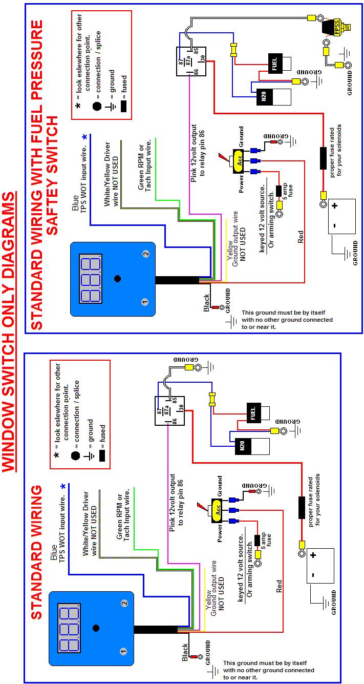
6 PROGRESSIVE WIRING DIAGRAMS Rev H


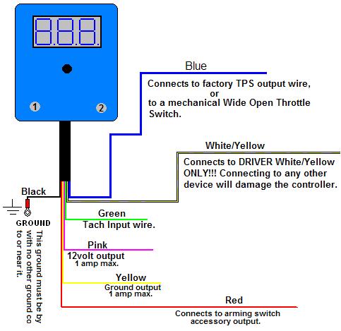
7 ADVANCED MODE: BLUE TPS WOT INPUT WIRE CONNECTION DIAGRAMS STANDARD MODE: BLUE TPS WOT INPUT WIRE CONNECTION DIAGRAM
8
DYNOTUNE 2 STAGE RPM WINDOW SWITCH WITH TPS INSTALLATION INSTRUCTIONS
 DYNOTUNE 2 STAGE RPM WINDOW SWITCH WITH TPS INSTALLATION INSTRUCTIONS Introduction: READ ALL INSTRUCTIONS BEFORE STARTING! This DynoTune device will control up to two stages of nitrous oxide. They are
# Traction Control Window Switch
 1 INSTRUCTIONS # 82085 Traction Control Window Switch Thank you for choosing products; we are proud to be your manufacturer of choice. Please read this instruction sheet carefully before beginning installation,
MAXIMIZER-II Progressive Nitrous Controller INSTALLATION AND USER MANUAL. MAXIMIZER-II rev A
 MAXIMIZER-II Progressive Nitrous Controller INSTALLATION AND USER MANUAL i Table of Contents Page 1. Installation Overview...1 1.1 MAXIMIZER-II Power Input...1 1.2 SOLENOID DRIVER Ground...1 1.3 Arming
Thank you for your purchase Off-ROad NOtice: PROduct WaRNiNgs:
 Thank you for your purchase. Please, read the instructions and watch the video before installing the JMS Progressive N20 Controller. Configuration and installation videos are available online: www.jms-nos.com.
Product Overview. Shift light turns on when RPM is above programmed shift point. Stage 2 activation light turns on when Stage 2 is active.
 These instructions will guide you through the setup, installation, and use of the Nitrous Outlet WinMax Window Switch. If you have any questions about the WinMax, please call our Tech Help Line at (254)
This document describes:
 Thank you for purchasing this product from ERM. We appreciate your interest in our unique product line as we try to offer our customers an alternative to today s traditional products. This programmable
AUTO-BLiP. User Manual Lotus INTELLIGENT DOWNSHIFTS. Version 1.0
 AUTO-BLiP INTELLIGENT DOWNSHIFTS www.auto-blip.com User Manual Lotus Version 1.0 Copyright 2012 Tractive Technology, LLC. All rights reserved. Page 1 WARNING Use of the AUTO-BLiP while driving could lead
This document describes:
 Thank you for purchasing this product from ERM Products. We appreciate your interest in our unique product line as we try to offer our customers an alternative to today s traditional products. This universal
PVI 1800/PVI Residential/Commercial Grid-Tied Photovoltaic Inverter WARRANTY MANUAL. Subject to Change REV , Solectria Renewables
 PVI 1800/PVI 2500 WARRANTY MANUAL Residential/Commercial Grid-Tied Photovoltaic Inverter 2009, Solectria Renewables Subject to Change REV 10.09 1 Product Warranty & RMA Policy 1.1 Warranty Policy The Solectria
SOLAR DASH CHARGING SYSTEM USER GUIDE
 SOLAR DASH CHARGING SYSTEM Doc 1.01 INST049 INSTALLATION STEP 1 Place 20 watt solar panel in the dash of the vehicle facing up. Note: For ideal results position the vehicle in a manner in which the solar
AUTO-BLiP. User Manual Chevrolet Corvette. Version 1.7
 AUTO-BLiP INTELLIGENT DOWNSHIFTS www.auto-blip.com User Manual 2008-2013 Chevrolet Corvette Version 1.7 Copyright 2012 Tractive Technology, LLC. All rights reserved. Page 1 WARNING Use of the AUTO-BLiP
Woolich Racing. Bike Harness Installation Instructions Suzuki Harness Type 4a GSX1300R (Hayabusa)
") Woolich Racing Bike Harness Installation Instructions Suzuki Harness Type 4a 2013+ GSX1300R (Hayabusa) 1) Introduction To connect your Woolich Racing product to the ECU ( Engine Control Unit or computer)
Woolich Racing Bike Harness Installation Instructions Suzuki Harness Type 4a 2013+ GSX1300R (Hayabusa) 1) Introduction To connect your Woolich Racing product to the ECU ( Engine Control Unit or computer)
AUTO-BLiP. User Manual Ford Mustang INTELLIGENT DOWNSHIFTS. Version 1.2
 AUTO-BLiP INTELLIGENT DOWNSHIFTS www.auto-blip.com User Manual 2015-2016 Ford Mustang Version 1.2 Copyright 2012 Tractive Technology, LLC. All rights reserved. Page 1 WARNING Use of the AUTO-BLiP while
INSTALL GUIDE Dodge/RAM 5.7L HEMI
 INSTALL GUIDE 2009-2017 Dodge/RAM 5.7L HEMI TABLE OF CONTENTS 3 GETTING STARTED 3 PARTS LIST 4 INSTALLATION INSTRUCTIONS 4 REMOVING THE STOCK INTAKE ASSEMBLY 6 INSTALLING THE AIR FILTER 7 INSTALLING THE
SELECT/DIRECT DEMO BOX USER GUIDE. INST164 Doc 1.00
 SELECT/DIRECT DEMO BOX USER GUIDE INST164 Doc 1.00 CONTENTS Using the Demo Box...2 Direct Dual Pole (Stinger) Demonstration...5 Select Dual Pole, Reefer, or Aux Demonstration...6 Switch Board Callouts...7
SELECT DIAGNOSTIC GUIDE. INST028 Doc 3.02
 SELECT DIAGNOSTIC GUIDE INST028 Doc 3.02 CONTENTS General Information...2 Select Call-Outs...3 Wire Diagram and Legend...4 Diagnostics...6 Excessive Voltage Drop Diagnostics...6 Static Diagnostics...7
Woolich Racing. Bike Harness Installation Instructions Hayabusa Gen 2 (08+)
") Woolich Racing Bike Harness Installation Instructions Hayabusa Gen 2 (08+) 1) Introduction To connect your Woolich Racing product to the ECU ( Engine Control Unit or computer) in your bike you need to
Woolich Racing Bike Harness Installation Instructions Hayabusa Gen 2 (08+) 1) Introduction To connect your Woolich Racing product to the ECU ( Engine Control Unit or computer) in your bike you need to
Wiring Installation Instructions for : Pressure. Wiring Installation Instructions for : Temperature. 2 1/16 Spek Pro Professional Racing Gauge
 Wiring Installation Instructions for : Pressure DIAGRAM 1 Pressure Sensor 1/8 NPT 3 AMP Wiring Installation Instructions for : Temperature GAUGE 12-Pin Wiring Harness & Plug Firewall Grommet DIAGRAM 2
AUTO-BLiP. User Manual Chevrolet Corvette. Version 1.2
 AUTO-BLiP INTELLIGENT DOWNSHIFTS www.auto-blip.com User Manual 1997-2004 Chevrolet Corvette Version 1.2 Copyright 2012 Tractive Technology, LLC. All rights reserved. Page 1 WARNING Use of the AUTO-BLiP
OPERATIONS MANUAL MODEL MT-500
 OPERATIONS MANUAL MODEL MT-500 Machine Serial Number: Specification Number: Engine Serial Number: SOLD & SERVICED BY SAFETY PRECAUTIONS AS STATED IN OSHA, THE EMPLOYER SHALL PERMIT ONLY THOSE EMPLOYEES
ASSEMBLY / OPERATION INSTRUCTIONS. Low Profile Motorcycle Dolly
 ASSEMBLY / OPERATION INSTRUCTIONS 1,500LB CAPACITY Low Profile Motorcycle Dolly Model: 03-CG1500-01(B1) WARNING BEFORE USE PLEASE READ ALL WARNINGS AND INSTRUCTIONS TO PREVENT SERIOUS INJURY Drop-Tail
AUTO-BLiP. User Manual Porsche INTELLIGENT DOWNSHIFTS. Version 1.2
 AUTO-BLiP INTELLIGENT DOWNSHIFTS www.auto-blip.com User Manual 2005+ Porsche Version 1.2 Copyright 2012 Tractive Technology, LLC. All rights reserved. Page 1 WARNING Use of the AUTO-BLiP while driving
INSTALL GUIDE Ford F L
 INSTALL GUIDE 2011-2014 Ford F-150 5.0L TABLE OF CONTENTS 3 GETTING STARTED 3 PARTS LIST 4 INSTALLATION INSTRUCTIONS 4 REMOVING THE STOCK INTAKE ASSEMBLY 5 INSTALLING THE AIR FILTER 6 INSTALLING THE HOUSING
WARRANTY POLICY. Grid-Tied Photovoltaic Inverters. Revision D. 2014, Solectria Renewables, LLC DOCIN
 WARRANTY POLICY Revision D 2014, Solectria Renewables, LLC DOCIN-070360 1 Product Warranty & RMA Policy 1. Warranty Policy Warranty Registration: It is important to have updated information about the inverter
PVI 60KW, PVI 82KW, PVI 95KW
 PVI 60KW PVI 82KW PVI 95KW WARRANTY MANUAL Commercial, Grid-Tied Photovoltaic Inverters 2008, Solectria Renewables LLC Subject to Change DOC-020099 rev 024 1 1 Product Warranty & RMA Policy Warranty Policy
OPERATION MANUAL Variable Speed Pump Controller Dated: 06/04/2013 Pump Down Application. Document No.: LMSII_V100_OM Page 1 of 8 Model-V100 LMS II
 Document No.: LMSII_V100_OM Page 1 of 8 LMS II Document No.: LMSII_V100_OM Page 2 of 8 1. Operation: When the wet well level rises above the on level set point, the lead pump will start after an adjustable
SCHNITZ MOTORSPORTS USER MANUAL AND INSTALLATION GUIDE PRO-MOD BATTERY VOLTS DIAGNOSTICS NOS PULSE FREQUENCY NOS DELAY TIME IN SECONDS
 SCHNITZ MOTORSPORTS DSC-CS "PRO-MOD" IGNITION CONTROLLER USER MANUAL AND INSTALLATION GUIDE COIL, (OPTIONAL) GA YELLOW, COIL, NEGATIVE GA WHITE, GA BLACK, SHIFT LIGHT +V OUTPUT PAGE 0 NOS ACTIVATION INPUT
INVERTER HARNESS INSTALLATION FOR FREIGHTLINER CASCADIA
 FOR FREIGHTLINER CASCADIA Part #: P808 1004FC 08/05/2014 Doc 1.04 INST065 Page 1 Step 1: Unpack the plate assembly and both positive and negative cables. INSTALLATION INSTRUCTIONS Step 2: Insert the negative
INSTALL GUIDE Silverado/Sierra L/6.2L
 INSTALL GUIDE 2014-2017 Silverado/Sierra 1500 5.3L/6.2L TABLE OF CONTENTS 3 GETTING STARTED 3 PARTS LIST 4 INSTALLATION INSTRUCTIONS 4 REMOVING THE STOCK INTAKE ASSEMBLY 7 INSTALLING THE AIR FILTER 8 INSTALLING
IV. PROOF OF PURCHASE: A warranty claim must be accompanied by proof of the date of purchase.
 PD9100 / 9200 SERIES POWER CONVERTER OWNERS MANUAL PROGRESSIVE DYNAMICS, INC. POWER CONVERTER LIMITED WARRANTY I. LIMITED WARRANTY: Progressive Dynamics, Inc. warrants its power converter to be free from
For questions or technical support, 1. Wiring Reference:
 Warning: Before proceeding you are obligated to read and agree to the terms and conditions attached to this manual. Misuse of this product may cause injury or death. Incorrect installation may cause damage
MSD Coil Power Booster for Ford 4.6L/5.4L Mod Motors 99-On PN 8740
 MSD Coil Power Booster for Ford 4.6L/5.4L Mod Motors 99-On PN 8740 ONLINE PRODUCT REGISTRATION: Register your MSD product online. Registering your product will help if there is ever a warranty issued with
USER MANUAL AND INSTALLATION GUIDE ENGINE RPM AND NOS SHIFT COUNTER NOS DELAY TIME IN SECONDS NOS START PERCENT NOS FINAL PERCENT
 SCHNITZ MOTORSPORTS DSC-9PS "PRO-STREET" IGNITION CONTROLLER USER MANUAL AND INSTALLATION GUIDE SHIFT LIGHT POSITIVE PAGE 2 SHIFT LIGHT GROUND PAGE 2 NOS SOLENOID GROUND 1GA ORANGE, FUEL SOLENOID GROUND
MSD 7AL-3, Ignition Control PN 7230
 MSD 7AL-3, Ignition Control PN 7230 Important: Read the instructions before attempting the installation. Parts Included: 1-7AL-3, PN 7230 1 - Parts bag (wires and connectors) 4 - RPM Modules 3000, 7000,
Owner s Guide CARS & CA4B5
 PROFESSIONAL SERIES Owner s Guide For Model: CARS & CA4B5 Deluxe Vehicle Remote Start and Keyless Entry System IMPORTANT NOTE: The operation of the Security and Convenience System as described in this
INSTALLATION INSTRUCTIONS 5" SINGLE CHANNEL ULTIMATE TACH
 Instr. No. 2650-887D INSTALLATION INSTRUCTIONS 5" SINGLE CHANNEL ULTIMATE TACH IMPORTANT WEAR SAFETY GLASSES 5 4 6 COPYRIGHT PATENT PENDING 3 7 8 PLAYBACK 9 2 0 1 AUTO METER PRODUCTS, INC. SYCAMORE, IL
SCHNITZ MOTORSPORTS PNC-202, 2-STAGE PROGRESSIVE NITROUS CONTROLLER USER MANUAL AND INSTALLATION GUIDE NOS PULSE FREQUENCY
 SCHNITZ MOTORSPORTS PNC-202, 2-STAGE PROGRESSIVE NITROUS CONTROLLER USER MANUAL AND INSTALLATION GUIDE NOS #2, FUEL SOLENOID(GROUND) 1GA PURPLE, PAGE 14 NOS #2 NITROUS SOLENOID(GROUND) 1GA PURPLE, PAGE
ASSEMBLY / OPERATION INSTRUCTIONS. Low Profile / Stand-Up Motorcycle Dolly
 ASSEMBLY / OPERATION INSTRUCTIONS 1,500LB CAPACITY Low Profile / Stand-Up Motorcycle Dolly Model: 03-CGPR1500-01(C) WARNING BEFORE USE PLEASE READ ALL WARNINGS AND INSTRUCTIONS TO PREVENT SERIOUS INJURY
Installation and Operation Guide
 Bus-Scan 500 RF Installation and Operation Guide All Content and Information are Copyright 2018-2019 Robotics Technologies, Inc. Features and Information are subject to change without notice. All Rights
MSD 6LS-2 Ignition Controller for Carbureted and EFI LS 2/LS 7 Engines PN 6012
 MSD 6LS-2 Ignition Controller for Carbureted and EFI LS 2/LS 7 Engines PN 6012 ONLINE PRODUCT REGISTRATION: Register your MSD product online. Registering your product will help if there is ever a warranty
MSD Pro-Billet Chevrolet HEI Distributor PN 83651, PN 8365/83653
 MSD Pro-Billet Chevrolet HEI Distributor PN 83651, PN 8365/83653 ONLINE PRODUCT REGISTRATION: Register your MSD product online. Registering your product will help if there is ever a warranty issue with
All products subject to this warranty must be returned for examination, repair or replacement to:
 Limited Warranty The software and sensors are warranted by the manufacturer, Toledo Integrated Systems, to be free from defects in workmanship for one year from the date of manufacturer s shipment. This
Two Channel Remote Shutdown Device
 Installation & Operation Standard Features: Two Channel Remote Shutdown Device I. Introduction Latched shutdown for increased safety Powerful transmitter with 300 feet range Waterproof sealed transmitter
ELECTRONIC TRACTION CONTROL USER MANUAL
 DRAG-SPORTSMAN N2O For ELECTRONIC TRACTION CONTROL USER MANUAL TELEPHONE 828.645.1505 FAX 828.645.1525 WWW.MORETRACTION.COM US PATENT 6,577,944 Disclaimer...2 Introduction... 3 How Does It Work. 4 Installation...
NISSAN 370Z INTELLI-KEY Rev.:
 Remote Starter NISSAN 70Z 009-00 INTELLI-KEY Rev.: 0096 009 Not included: x Fuse 5Amp x s Amp x Relays Override OEM Transponder Immobilizer Via Data (No Key Required). Interfaces directly with the latest
AC Irrigation and Propagation Controllers I Four Station, 5006-I and 5006-IP Six Station
 AC Irrigation and Propagation Controllers 5004-I Four Station, 5006-I and 5006-IP Six Station I N S T R U C T I O N M A N U A L Table of contents Introduction 1 1. Specifications 1 2. Controller Mounting
Owner s Guide. ca5154
 PROFESSIONAL SERIES Owner s Guide for models: ca5154 Automatic / Manual Transmission Remote Start and Keyless Entry System IMPORTANT NOTE: The operation of the Security and Convenience System as described
i n s t r u c t i o n m a n u a l
 i n s t r u c t i o n m a n u a l 8006 Six-Station AC Timer Residential/Light Commercial Independent Program Irrigation Controllers Installation, Programming and Operating Instructions Features Operates
Owner s Guide. ca5354
 PROFESSIONAL SERIES Owner s Guide for models: ca5354 Deluxe Vehicle Remote Start System with 900Mhz 2 Way Confirming LED Remote Control IMPORTANT NOTE: The operation of the Security and Convenience System
USER MANUAL AND INSTALLATION GUIDE TIMER DELAY IN SECONDS SHIFT STYLE & SHIFT COUNTER TIMER DURATION NOS DELAY TIME IN SECONDS NOS START PERCENT
 SCHNITZ MOTORSPORTS DSC-TG0- "TOP-GAS " IGNITION CONTROLLER USER MANUAL AND INSTALLATION GUIDE COIL, (OPTIONAL) GA YELLOW, PAGE COIL, NEGATIVE GA WHITE, PAGE SHIFT LIGHT GROUND 0GA BROWN, PAGE 0 SHIFT
INSTRUCTION and OPERATIONS MANUAL. for
 INSTRUCTION and OPERATIONS MANUAL for SPEED-O-CALIBRATOR Locomotive Speedometer Calibrator Unit MODEL NUMBER 16470-00 CAUTION Be sure to read and become thoroughly familiar with the entire contents of
There are two types of installations depending on how the current nitrous oxide system is installed.
 INSTRUCTIONS Nitrous Level Gauge (Part #82395) Thank you for choosing products; we are proud to be your manufacturer of choice. Please read this instruction sheet carefully before beginning installation,
Owner s Guide CARS & CA2LCD5
 PROFESSIONAL SERIES Owner s Guide For Models: CARS & CA2LCD5 Deluxe Vehicle Remote Start and Keyless Entry System IMPORTANT NOTE: The operation of the Security and Convenience System as described in this
MSD Single Cylinder Programmable Ignition PN 4217
 MSD Single Cylinder Programmable Ignition PN 4217 Parts Included: 1 - PN 4217 1 - PN 4217 Wire Harness 1 - CD Rom 9609 1 - Parts Bag 1 - Serial Cable WARNING: During installation, disconnect the battery
PRO-COMP/PHANTOM TACH
 2650-895B INSTALLATION INSTRUCTIONS 5 single channel PRO-COMP/PHANTOM TACH COPYRIGHT PATENT 5 4 6 3 PENDING 7 8 PLAYBACK 9 2 0 1 AUTO METER PRODUCTS, INC. SYCAMORE, IL USA MADE RPM x 1000 IN USA MENU SELECT
Installation & Operators Manual
 Installation & Operators Manual Model Serial Number Purchase Date 2007-2008 SegVator, LLC Patent Pending All Rights Reserved Important Safety Information Make sure the vehicle has a properly installed
Instructions 3A4793B EN. See page 3 for a complete list of model descriptions and part numbers.
 Instructions Variable Frequency Drives 3A4793B EN Variable frequency drives (VFDs) to power and control electric motor driven agitators. For professional use only. Not approved for use in explosive atmospheres
Users Guide for Ac-sync
 Problem solved. Users Guide for Ac-sync Thank you for choosing Anywhere Cart! The AC-SYNC is designed to sync, charge and store 1-36 ipads or tablets. Adjustable device divider bays allow fitment of any
Owner s Guide. ca6154
 PROFESSIONAL SERIES Owner s Guide For Models: ca6154 Deluxe Vehicle Security and Remote Start System IMPORTANT NOTE: The operation of the Security and Convenience System as described in this manual is
Lingenfelter ECSS-001 Ethanol Content Sensor Signal Simulator Installation & Operating Instructions
 Lingenfelter ECSS-001 Ethanol Content Sensor Signal Simulator Installation & Operating Instructions PN: L460350085 Revision - 1.6 Lingenfelter Performance Engineering 1557 Winchester Road Decatur, IN 46733
Installation and Operation Guide
 Bus-Scan CR2 RF Installation and Operation Guide All Content and Information are Copyright 2018 Robotics Technologies, Inc. Features and Information are subject to change without notice. All Rights Reserved.
INSTALL GUIDE Jeep Wrangler JK 3.6L V6
 INSTALL GUIDE 2012-2017 Jeep Wrangler JK 3.6L V6 TABLE OF CONTENTS 3 GETTING STARTED 3 PARTS LIST 4 INSTALLATION INSTRUCTIONS 4 REMOVING THE STOCK INTAKE ASSEMBLY 6 INSTALLING THE HOUSING 7 INSTALLING
NISSAN MAXIMA INTELLI-KEY Rev.:
 Remote Starter NISSAN MAXIMA 2009-2011 INTELLI-KEY Rev.: 20091126 20110921 Not included: 1x Fuse 15Amp 3x s 3x Relays Override OEM Transponder Immobilizer Via Data (No Key Required). Interfaces directly
BRAVO Inverter/Battery Charger. Table of Contents
 BRAVO 1050 Inverter/Battery Charger Table of Contents Introduction... 2 General Description... 2 Specifications... 3 Installation: Hardwire Units... 4 Operation: Hardwire Units... 5-6 Installation: GFCI
CAPACITOR ACTUATED PORTABLE STARTER CAPS USER GUIDE. INST048 Doc 3.01
 CAPACITOR ACTUATED PORTABLE STARTER CAPS USER GUIDE INST048 Doc 3.01 CONTENTS General Information...2 Charts...3 Before First Use...4 Safety Requirements...5 What to Expect from the CAPS...5 CAPS Diagram...6
The function of this Dynamic Active Probe has divided into three preferences on the screen main Menus:
 1.0 Introduction: This probe is designed to provide an additional help to automotive technicians in trouble shooting of electrical circuits problems in the car. Apart from using the normal multi tester,
CA 5054 Owner s Guide
 PROFESSIONAL SERIES CA 5054 Owner s Guide Remote Start and Keyless Entry System IMPORTANT NOTE: The operation of the Security and Convenience System as described in this manual is applicable to most vehicles.
Owner s Guide APS596Z
 Owner s Guide For Models: APS596Z Security / Keyles Entry System IMPORTANT NOTE: The operation of the Security and Convenience System as described in this manual is applicable to most vehicles. However,
MSD Pro-Billet Small Diameter Ready-to-Run Ford V8 Distributor PN 8350/83503; 351C-460, PN 8354; 351W PN 8352/83523; 289/302
 MSD Pro-Billet Small Diameter Ready-to-Run Ford V8 Distributor PN 8350/83503; 351C-460, PN 8354; 351W PN 8352/83523; 289/302 ONLINE PRODUCT REGISTRATION: Register your MSD product online. Registering your
AUTOMATIC AND MANUAL TRANSMISSION MODELS* *MUST USE M SERIES REMOTE STARTER!
 REV.2011.7.22 80 SERIES Advanced Remote Starters & Vehicle Security Systems AUTOMATIC AND MANUAL TRANSMISSION MODELS* *MUST USE M SERIES REMOTE STARTER! WARING: NEVER USE AN AUTOMATIC TRANSMISSION STARTER
ODY-05-2 VOLTMETER FOR REMOTE MONITORING
 ODY-05-2 VOLTMETER FOR REMOTE MONITORING Introduction: The Odyssey gauge series from Dakota Digital, Inc. incorporates the reliability and quality of our standard gauges, along with several unique features
Power. On Your Terms.
 Power. On Your Terms. 10 YEAR LIMITED WARRANTY PHI 1310 TM 1 SIMPLIPHI POWER, INC. REV102016 10 YEAR LIMITED WARRANTY: PHI 1310 TM LIMITED PRO-RATED WARRANTY COVERAGE The SimpliPhi Power PHI 1310 as supplied
MSD 6-Hemi Controller for Carbureted and EFI Hemi Engines PN 6013
 MSD 6-Hemi Controller for Carbureted and EFI Hemi Engines PN 6013 Parts Included: 1 - Ignition Controller, PN 6013 1 - Pro-Data+ Software CD 1 - Parts Bag 1 - Mounting Template Optional Accessories: Hand
Installation Guide. Index. Vehicle Canbus Integration System
 Platform: CANMAX00 Rev.: 20003 Update Alert: Firmware updates are posted to the web on a regular basis. We recommend that you check for firmware and/or install guide updates prior to installing this product.
MSD Pro-Billet Ready-to-Run Chrysler V8 Distributor PN 8388; 318, 340, 360, PN 8386; 383, 400 PN 8387; 426, 440
 MSD Pro-Billet Ready-to-Run Chrysler V8 Distributor PN 8388; 318, 340, 360, PN 8386; 383, 400 PN 8387; 426, 440 ONLINE PRODUCT REGISTRATION: Register your MSD product online. Registering your product will
Parts Manual. Model: 1550-D
 Parts Manual Model: 550-D Covers 50-K-50TKZ8Y2-0250 through Sold & Serviced By: Contents Quick Order List... Hopper and Plastic...3 Push Beam and Sight Gauge...5 Engine Compartment...7 Hood Assembly...9
FOR SERVICE SEND TO: AUTO METER PRODUCTS, INC. 413 W. Elm St., Sycamore, IL USA (815) us at
 us at") 2650-887F INSTALLATION INSTRUCTIONS 5 single channel ultimate tach COPYRIGHT PATENT 5 4 6 3 PENDING 7 8 PLAYBACK 9 2 0 1 AUTO METER PRODUCTS, INC. SYCAMORE, IL USA MADE R P M X1000 IN USA ENTER START PAUSE
2650-887F INSTALLATION INSTRUCTIONS 5 single channel ultimate tach COPYRIGHT PATENT 5 4 6 3 PENDING 7 8 PLAYBACK 9 2 0 1 AUTO METER PRODUCTS, INC. SYCAMORE, IL USA MADE R P M X1000 IN USA ENTER START PAUSE
EMISSION CONTROL WARRANTY STATEMENT
 EMISSION CONTROL WARRANTY STATEMENT YOUR WARRANTY RIGHTS AND OBLIGATIONS The California Air Resources Board, U.S. EPA and Zenith Power Products LLC (ZPP) are pleased to explain the emission control system
INSTALLATION AND OPERATING INSTRUCTIONS
 PRO-CUBE INSTALLATION AND OPERATING INSTRUCTIONS Congratulations on your purchase of the most advanced combination delay box/timer unit available for today s precision drag racing. The new PRO-CUBE is
Tiller Lock Assembly
 2 1 4 1 2 4 1 2 4 1 7 6 7 8 Positioning Pin Assembly 1 Positioning Pin 2 Spring Black Knob 5 4 1 2 2 1 Tiller Lock Assembly 1 2 4 Threaded Rod Rotating Rod Spring Flat Washer 5 6 7 8 C Type Plastic Washer
Owner s Guide PR1BZ PR1BZLR
 Owner s Guide For Models: PR1BZ PR1BZLR PRORS RF Upgrade Kit IMPORTANT NOTE: The operation of the Security and Convenience System as described in this manual is applicable to most vehicles. However, due
MSD 6-Mod Controller for Carbureted and EFI Gen III Engines PN 6011
 MSD 6-Mod Controller for Carbureted and EFI Gen III Engines PN 6011 ONLINE PRODUCT REGISTRATION: Register your MSD product online. Registering your product will help if there is ever a warranty issue with
Owner s Guide CA 5055
 PROFESSIONAL SERIES Owner s Guide For Model: CA 5055 Vehicle Remote Start and Keyless Entry System IMPORTANT NOTE: The operation of the Security and Convenience System as described in this manual is applicable
ASM Maxi Poles. Instruction-Parts B Series. For the application of architectural paints and coatings.
 Instruction-Parts ASM Maxi Poles 312483B For the application of architectural paints and coatings. 3400 Series 4050 psi (27.92 MPa, 280 bar) Maximum Working Pressure Important Safety Instructions Read
TRAILER AUXILIARY POWER SYSTEM (TAPS) INSTALLATION GUIDE V1.10
 INSTALLATION GUIDE V1.10") TRAILER AUXILIARY POWER SYSTEM (TAPS) INSTALLATION GUIDE V1.10 TAPS INSTALLATION GUIDE V1.10 1 TRAILER AUXILIARY POWER SYSTEM CONTENTS General Information and System Logic... 2 Diagrams... 3 System Diagram
TRAILER AUXILIARY POWER SYSTEM (TAPS) INSTALLATION GUIDE V1.10 TAPS INSTALLATION GUIDE V1.10 1 TRAILER AUXILIARY POWER SYSTEM CONTENTS General Information and System Logic... 2 Diagrams... 3 System Diagram
WARNING. Instructions for Guidelights and Chargers. How SnapPower Products Work
 Instructions for Guidelights and Chargers WARNING Failure to turn OFF electrical power prior to installing or removing the Guidelight or Charger can result in electrical shock, fires, and/or death. www.snappower.com
Installation Instructions for the Lingenfelter Fan and Pump Manual Override Kit
 Installation Instructions for the Lingenfelter Fan and Pump Manual Override Kit PN: L300180000 v1.1 Lingenfelter Performance Engineering 1557 Winchester Road Decatur, IN 46733 (260) 724-2552 (260) 724-8761
MSD LS-1/LS-6 Controller for Carbureted and EFI Gen III Engines PN 6010
 MSD LS-1/LS-6 Controller for Carbureted and EFI Gen III Engines PN 6010 Parts Included 1 Ignition Controller, PN 6010 1 Pro-Data+ Software CD 1 Harness 1 Parts Bag 6 Timing Modules Optional Accessories
Instruction Manual. OEM Frameless Rear View Replacement Mirror Monitor with 7.2" Dual Display RVS Reverse With Confidence 1
 Instruction Manual OEM Frameless Rear View Replacement Mirror Monitor with 7.2" Dual Display RVS-718-7 1 NOTE! Please read all of the installation instructions carefully before installing the product.
ATD-5540 Digital Automotive Engine Analyzer/Multimeter Owner s Manual
 ATD-5540 Digital Automotive Engine Analyzer/Multimeter Owner s Manual Features: Made in China to ATD Tools, Inc. Specifications Visit us at www.atdtools.com ATD5540_rev_0817 ATD-5540 Contents SAFETY WARNING
The Ultimate Smart Grid Solution INSTRUCTION MANUAL
 ECOWISE EW20/1 EW30/1 The Ultimate Smart Grid Solution INSTRUCTION MANUAL Welcome! Congratulations on selecting the ECOWISE unit to manage your energy supply needs. ECOWISE units reduce the amount of electric
KOKO BOOST USER GUIDE
 KOKO BOOST USER GUIDE Thank you for purchasing the Suhr Koko Boost. Please take the time to read this manual to get the most out of your pedal. The more you familiarize yourself with the features of this
DIGIGAUGE P R E S S U R E D I S P L A Y S Y S T E M I N S T R U C T I O N M A N U A L
 DIGIGAUGE P R E S S U R E D I S P L A Y S Y S T E M I N S T R U C T I O N M A N U A L Thank you for purchasing DigiGauge by ZAETECH Disclaimer DigiGauge is for show and off road use only. By using this
The Ultimate Smart Grid Solution INSTRUCTION MANUAL
 ECOWISE EW30/1 The Ultimate Smart Grid Solution INSTRUCTION MANUAL Welcome! Congratulations on selecting the ECOWISE unit to manage your energy supply needs. ECOWISE units reduce the amount of electric
User Manual SH Slag Removal Tool for use on laser cutting machines with minimum 1.25 between slats
 User Manual SH2 67087 Slag Removal Tool for use on laser cutting machines with minimum 1.25 between slats 1. Description The tool is moved along the slats on the bed of a laser machine to remove slag that
CHIP. Reverse Osmosis System Controller Documentation
 CHIP Reverse Osmosis System Controller Documentation Document Revised June, 2017. 2017 icontrols Technologies Inc icontrols Technologies Inc. 1821 Empire Industrial Court, Suite A Santa Rosa, CA 95403
MSD Pro-Billet Digital E-Curve Distributor PN U.S. Patent
 MSD Pro-Billet Digital E-Curve Distributor PN 8394 - U.S. Patent 6820602 ONLINE PRODUCT REGISTRATION: Register your MSD product online. Registering your product will help if there is ever a warranty issue
10 Year Limited Warranty
 Power. On Your Terms. 10 Year Limited Warranty PHI 2.7 TM PHI 3.5 TM 60A SIMPLIPHI POWER, INC. REV020618 10 Year Limited Warranty: PHI 2.7 TM PHI 3.5 TM 60A 24V 48V Limited Pro-Rated Warranty Coverage
1. Contents 1. CONTENTS INTRODUCTION SAFETY WARNINGS POWER TILT STANDARD OPERATING INSTRUCTIONS... 5.
 1. Contents 1. CONTENTS..... 2. INTRODUCTION..... 3. SAFETY WARNINGS..... 4. POWER TILT STANDARD OPERATING INSTRUCTIONS....... 5. POWER SEAT LIFT STANDARD OPERATING INSTRUCTIONS...... 6. POWER TILT / SEAT
MSD Pro-Billet Digital E-Curve Distributor Ford 289/302 PN U.S. Patent
 MSD Pro-Billet Digital E-Curve Distributor Ford 289/302 PN 8503 - U.S. Patent 6820602 ONLINE PRODUCT REGISTRATION: Register your MSD product online and you ll be entered in our monthly 8.5mm Super Conductor