MTS 5100 ENGINE ANALYZER
|
|
|
- Josephine Jordan
- 6 years ago
- Views:
Transcription
1 MTS 5100 ENGINE ANALYZER Operator s Manual
2 Vetronix Corporation MTS 5100 Engine Analyzer Operator s Manual for Software Version 2.0 Copyright 2003 Manual P/N Ver. B The trademarks, logos, and service marks ( Marks ) displayed in this document are the property of Vetronix or other third parties. Users are not permitted to use these Marks without the prior written consent of Vetronix or such third party which may own the Mark. Vetronix is a registered trademark of Vetronix Corporation. Mastertech is a registered trademark of Vetronix Corp. Printed in USA 12/03 Vetronix Corporation Proprietary Statement This entire document and all information contained herein are proprietary, confidential, and exclusive trade secret property of Vetronix Corporation and shall not be reproduced, duplicated, or copied in whole or in part, or made available to any other person, firm, or corporation without the prior written permission of Vetronix Corporation.
3 SOME THINGS YOU SHOULD KNOW WARNING! When performing any checks with the engine running in an enclosed space such as a garage, be sure there is proper ventilation. Never inhale exhaust gases; they contain carbon monoxide, a colorless, odorless, extremely dangerous gas which can cause unconsciousness or death. CAUTION! CAUTION Always set the parking brake securely and block the drive wheels before performing any checks or repairs on the vehicle. DISCLAIMER The MTS 5100 tester is designed for use by trained service personnel only. The tester has been developed for the sole purpose of diagnosing and repairing automotive electronic systems. Every attempt has been made to provide complete and accurate technical information based on factory service information available at the time of publication. However, the right is reserved to make changes at any time without notice. FCC COMPLIANCE This equipment has been tested and found to comply with the limits for a Class A digital device, pursuant to Part 15 of the FCC Rules. These limits are designed to provide reasonable protection against harmful interference when the equipment is operated in a commercial environment. This equipment generates, uses, and can radiate radio frequency energy and, if not installed and used in accordance with the instruction manual, may cause harmful interference to radio communications. Operation of this equipment in a residential area is likely to cause harmful interference in which case the user will be required to correct the interference at his own expense.
4 Table of Contents 1. INTRODUCTION TO THE MTS INTRODUCTION... 1 ABOUT THE OPERATOR S MANUAL... 1 SAFETY GUIDELINES... 2 MTS 5100 FEATURES... 3 General Functions... 3 Primary Ignition... 3 Secondary Ignition... 3 Graphing Multimeter... 4 DVOM... 4 Oscilloscope... 4 Snapshot... 4 File Manager... 5 Engine Tests... 5 Ignition Scope Connections... 6 Keypad Operation Functions... 7 Communication Connections... 7 Standard Leads... 8 Optional Leads Touch Screen Operation GENERAL INFORMATION Entering the Test Vehicle Selecting Vehicle from Database Selecting Manual Vehicle Setup Last Vehicle Selection Freeze Run Save Recall Print Upload Powering Down the Tester USING THE 4-CHANNEL OSCILLOSCOPE INTRODUCTION CONNECTING LEADS PATTERN DISPLAY Manual Setup Component Selection Current Waveforms Vacuum/Pressure Example Waveform Signal Finder Default Setup CHANNEL CONTROLS Volts/Division Offset MTS 5100 Engine Analyzer TOC-i
5 AC/DC Coupling DC Coupling AC Coupling Ground Coupling Time/Division TRIGGER SETUP Trigger Source Trigger Type Auto (Automatic) Trigger Normal Trigger Single Shot Trigger Free Run Trigger Level Trigger Position Trigger Edge GLITCH CAPTURE FREEZE CURSORS Cursor Controls Cursor Button Cursor Select Button Lock/Unlock Cursor Button Cursor A/B Button Cursor Channel Selection Cursor Movement ENGINEERING MODE COIL ON PLUG (COP) IGNITION SYSTEMS Primary Ignition Testing Hookup Instructions Primary vs. Secondary Primary Current Ramping PRIMARY IGNITION INTRODUCTION CONNECTING FOR PRIMARY IGNITION Distributor Ignition System (DI) Connecting the Leads Coil On Plug (COP) Ignition System Connecting the Leads PATTERN DISPLAY Cylinder Selection Single Cylinder Parade Raster Superimposed Firing Volts Barchart SETTINGS Volts / Division Time / Division Setup Button Main Button MTS 5100 Engine Analyzer TOC-ii
6 Trigger Position Trigger Cylinder Ground Offset Pattern Spacing Lead Help Button Show Vehicle Button ACTIVE BUTTONS SUMMARY SECONDARY IGNITION INTRODUCTION CONNECTING FOR SECONDARY IGNITION Distributor Ignition System (DI) Connecting the Leads Electronic Ignition System (DIS) Spider Leads and Junction Box Connecting the Leads Coil Near Plug (CNP) Ignition Systems Connecting the Leads Coil On Plug (COP) Ignition Systems Connecting the Leads Unique Ignition Systems Ford: Dual Plug Distributorless Ignition System Ford: Multi-Strike Ignition System General Motors: Integrated Direct Ignition (IDI) Nissan: NAP-Z Ignition System PATTERN DISPLAY Cylinder Selection Single Cylinder Parade Raster Superimposed Firing kv Barchart Power/Waste Comparison SETTINGS (kv) Volts / Division Time / Division Setup Button Main Button Trigger Position Trigger Cylinder Ground Offset Pattern Spacing Lead Help Button Show Vehicle Button ACTIVE BUTTONS SUMMARY SECONDARY QUICK CHECK INTRODUCTION CONNECTING FOR QUICK CHECK SETTINGS MTS 5100 Engine Analyzer TOC-iii
7 Setup Button Main Button Trigger Position Button Lead Help Button Ground Offset (kv) Volts / Division Time / Division ACTIVE BUTTONS SUMMARY VACUUM WAVEFORM INTRODUCTION CONNECTING THE LEADS TESTING TIPS CALIBRATING THE VACUUM PROBE PATTERN DISPLAY Vacuum Waveform % Vacuum Per Cylinder SETTINGS Units/Div Smoothing Setup Button ACTIVE BUTTONS SUMMARY CRANKING KV TEST INTRODUCTION CONNECTING THE LEADS Distributor Ignition System (DI) Connecting the Leads Electronic Ignition System (DIS) Spider Leads and Junction Box Connecting the Leads Coil Near Plug (CNP) Ignition Systems Connecting the Leads BEGINNING THE TEST TEST SCREEN Live/Min/Max/Avg Data Engine Information Engine Data Active Buttons Start Test Lead Help Trig Cyl Cyl Help EXIT Keypad Button Help Keypad Button RUNNING THE TEST DISPLAYING RESULTS Min/Max/Avg Data Pass/Fail Indicator MTS 5100 Engine Analyzer TOC-iv
8 Average RPM Average kv Cranking kv Threshold Action Buttons Re-Test Button Save Button Print Button EXIT Keypad Button HELP Keypad Button SAVING AND PRINTING RESULTS SETUP kv Threshold kv Test Duration Default Settings Continue Cancel ACTIVE BUTTONS SUMMARY CYLINDER TESTS CYLINDER BALANCE CYLINDER BALANCE INTRODUCTION Overview MANUAL VS. AUTOMATED TEST Manual Test Automated Test CONNECTING THE LEADS SETTING UP THE TEST Selecting the Vehicle Calibrating the Vacuum Probe Selecting the Test Mode Setting Ignition Disable Duration RUNNING THE MANUAL TEST Manual Balance Test Initial Screen Manual Balance Enable/Disable State Completing the Manual Test Manual Test Active Menu Keys Summary RUNNING THE AUTOMATED TEST Automated Balance Enable/Disable State Completing the Automated Test Automated Test Active Menu Keys Summary SAVING AND PRINTING RESULTS Freeze Button Print Save Run Recall FAILED CYLINDER ID FAILED CYLINDER ID INTRODUCTION Overview CONNECTING THE LEADS MTS 5100 Engine Analyzer TOC-v
9 If You Are Having a Problem STARTING THE TEST Selecting the Vehicle Entering VIN/Notes RUNNING THE TEST Clearing DTCs Performing the Failed Cylinder ID Test Test Time Live Parameters Target Data Live Data Start Test Button Aborting the Test EVALUATING TEST RESULTS DATA Test Results Display Mode Cylinder ID Display Mode Test Log Display Mode Test Information Select Test SAVING, RECALLING, AND PRINTING RESULTS Saving Data Save Test Results Save Current Screen Print Screen Recalling Files Printing Files Text Print Screen Print Uploading Files GRAPHING MULTIMETER INTRODUCTION CONNECTING THE LEADS OPERATING MODES Operating Mode Button DC Voltage Frequency DC Low Current DC High Current Pulse Width Duty Cycle Temperature Pressure Vacuum RPM SETTINGS Units/Division Time/Division Glitch CAPTURE Freeze Lead Help Pos Trig / Neg Trig MTS 5100 Engine Analyzer TOC-vi
10 Time Low/High % Low/High Minimum/Maximum/Average Reset DIGITAL VOLT OHM METER (DVOM) INTRODUCTION GETTING STARTED Connecting the Leads OPERATING MODES DC Voltage AC Voltage Resistance Continuity Diode Check CONTROLS Minimum/Average/Maximum Values Reset Measurement Range Print SNAPSHOT INTRODUCTION SETTING UP A SNAPSHOT Trigger Point Adjusting Trigger Point Snapshot Length Adjusting Snapshot Length Continue/Cancel CAPTURING A SNAPSHOT Snapshot Controls Main Menu Trigger/Stop Recording Indicator PLAYBACK MODE Selecting File in Memory Playback Controls Snapshot Play/Stop Freeze/Run File List Save Keypad Arrow Buttons Adjusting Settings during Playback Progress Indicator WARNING MESSAGES Unsaved Snapshot Overwrite Saved Snapshot MTS 5100 Engine Analyzer TOC-vii
11 12. FILE MANAGER INTRODUCTION File Naming Convention Capacity/Free Space/Total Files Indicator FILE MANAGER CONTROLS Detail View/List View View File Edit Notes Snapshot/Bitmap/Text Utilities Menu UTILITIES MENU CONTROLS Search TechView Upload Format Internal Flash Delete File Menu WARNING MESSAGES Internal Flash Full File Corruption Detected ANALYZER UTILITIES SETUP Set Date and Time Back Light On/Off Configure Network IP Address Measurements and Settings Units of Measure Cranking Test Setup Ignition Disable Duration TOOLS Software Version Number Self Tests RS-232: Com 1: Test RS-232: Com 2: Test LCD Test TouchScreen Test Calibration Calibrate Vacuum Probe Calibrate Pressure Transducer Calibrate Touch Screen Calibrate Auxiliary Port Charge Battery Format Internal Flash Enable Ignition Demonstration FILE MANAGER FILE TRANSFER UTILITY, VERSION UPLOADING FILES VIEWING UPLOADED FILES MTS 5100 Engine Analyzer TOC-viii
12 ABORTING THE UPLOAD PROCESS DELETING FILES SELECTING A DESTINATION DIRECTORY SELECTING A PC COM PORT TESTING THE PC COM PORT TOGGLE VIEW FILE NAMING CONVENTION A. MTS 5100 WARRANTY B. SERVICE AND REPAIR INSTRUCTIONS C. SPECIFICATIONS D. VEHICLES WITH ELECTRONIC IGNITION (DIS) Audi Chrysler ford General Motors Honda Hyundai Isuzu Kia Land Rover Lexus Mazda (8th VIN Position) Mazda (Engine Code) Mercedes Benz Mitsubishi Subaru Suzuki Toyota Volkswagen (Engine Code) Volkswagen (5th VIN Position) Volvo E. OSCILLOSCOPE COMPONENT CATEGORIES F. GLOSSARY INDEX MTS 5100 Engine Analyzer TOC-ix
13 1. INTRODUCTION TO THE MTS 5100 INTRODUCTION Congratulations on your decision to purchase this dynamic Vetronix product. Designed for professional automotive technicians, the MTS 5100 is a high speed data acquisition product. The MTS 5100 utilizes a real-time operating system to run a RISC based computing environment, giving you lightning fast measurement capabilities. This hand-held state-of-the-art tester contains a number of diagnostic instruments providing automotive professionals with the tools required to diagnose sophisticated electrical and mechanical systems on today s modern vehicles. The MTS 5100 touch screen user interface enables you to select from a number of different test modes such as 4-Channel Oscilloscope, Graphing Multimeter, DVOM, Vacuum Waveform, and Primary/Secondary Ignition. You can configure these functions to allow you to take charge of the diagnostic process and let you perform circuit testing down to a component level. Thank you for choosing Vetronix. We sincerely look forward to our continued partnership in fulfilling your automotive diagnostic equipment and support needs. ABOUT THE OPERATOR S MANUAL This manual is a useful product introduction and operation guide to help you get started. Complete instructions for operating the user-friendly software contained in the MTS 5100 is also provided. After reading the manual you may find that you only need to refer to the on-board analyzer Help function to help you operate the MTS Procedures and guidelines are provided for safe and accurate operation of the MTS Information that is very important to your safety or that is crucial for accurate readings and operation of the analyzer are identified with the headings described in Table 1-1, Notations Used in This Manual. MTS 5100 Engine Analyzer Page 1
14 Chapter 1 Introduction to the MTS 5100 INFORMATION NOTE Provides helpful hints, clues, ideas. EXPLANATION CAUTION! CAUTION WARNING! Alerts you to conditions or actions that can cause: personal injury if you don t follow the instructions. damage to products, accessories, property, or the environment. inaccurate readings because of misuse of equipment. Alerts you to potentially hazardous conditions that can cause serious injury or death if you don t follow the instructions. Table 1-1: Notations Used in This Manual SAFETY GUIDELINES Read the instructions in this manual before using the MTS 5100 Engine Analyzer. The AC Power Supply must be plugged into a properly grounded AC power outlet. CAUTION! CAUTION Avoid using the AC power supply on wet floors or other wet surface conditions. All test probe leads and cables should be routed in such a way that they do not come in contact with the engine fan or any other moving components on the engine. Also try to keep the leads away from hot surface areas. Because of snap acceleration testing, wheel chocks should be used on all types of vehicles. Safety goggles should be worn to protect your eyes. A fire extinguisher, rated for chemical and electrical fire, should be present at all times. Make sure to stay out of the direct line of the fan blades when working under the hood. WARNING! Ignition systems on most vehicles can generate extremely high voltages. Late model ignition systems such as Distributorless Ignition and Coil-On- Plug can generate voltages high enough to stop your heart. Use extreme caution when working with these systems. MTS 5100 Engine Analyzer Page 2
15 Chapter 1 Introduction to the MTS 5100 MTS 5100 FEATURES FIGURE 1-1. MTS 5100 Engine Analyzer GENERAL FUNCTIONS The MTS 5100 operates as a stand alone diagnostic platform. Using the many different features of the MTS 5100, you have the capability of displaying and storing any number of signals available on an automobile. Some of the general functions of the MTS 5100 are as follows. Primary Ignition Primary Ignition connection supports high voltage (600 volts) input, which is compatible with the following ignition types: DI (Distributor Ignition) External Coil DI (Distributor Ignition) Internal Coil COP (Coil On Plug) Ignition Secondary Ignition Secondary Ignition connection is used to support all types of secondary ignition signals. DI (Distributor Ignition) External Coil DI (Distributor Ignition) Internal Coil EI (Distributorless Ignition) CNP (Coil Near Plug) Ignition COP (Coil On Plug) Ignition MTS 5100 Engine Analyzer Page 3
16 Chapter 1 Introduction to the MTS 5100 Graphing Multimeter The Graphing Multimeter plots circuit operation over an extended period of time. Measurements include: DC Voltage DC Low Current DC High Current Frequency Pulse Width Duty Cycle RPM Temperature Vacuum Pressure DVOM The DVOM is used to digitally display the numerical value measured by the MTS The DVOM uses ¾" banana jack spacing, so all of your standard leads work. Measurements include: DC Voltage AC Voltage Resistance Continuity Diode Check Oscilloscope The 4-Channel Oscilloscope allows you to view multiple signals simultaneously and supports a wide variety of voltages and sampling speeds. You can select a vehicle component and allow the MTS 5100 to set up for the expected signal or manually change your oscilloscope settings. Snapshot The Snapshot function gives you the ability to capture, save, and playback a length of data collected from a vehicle. When a snapshot is captured, the MTS 5100 collects raw data from the vehicle for a length of time you select. Snapshots can be played back in real time or carefully examined by scrolling through the snapshot manually. Snapshots can be captured and played back in the following operating modes: Secondary Ignition Primary Ignition 4-Channel Oscilloscope Graphing Multimeter Vacuum Waveform MTS 5100 Engine Analyzer Page 4
17 Chapter 1 Introduction to the MTS 5100 File Manager The File Manager is a utility that allows you to view and manipulate all saved screen captures and snapshot files. The following functions are available in the File Manager: Viewing saved files Deleting one or multiple files Viewing detail information about a file Adding information about a file Formatting Internal Flash Searching files for key words Engine Tests Engine Tests are tests which allow you to analyze the engine s mechanical operation. The following Engine Tests are currently available: Vacuum Waveform Cranking kv Cylinder Tests: Failed Cylinder ID Cylinder Balance MTS 5100 Engine Analyzer Page 5
18 Chapter 1 Introduction to the MTS 5100 IGNITION SCOPE CONNECTIONS NOTE Make sure that all ground leads are securely attached to a good ground. A bad ground connection may display inaccurate data. Figure 1-2 shows the location of each described connection. FIGURE Engine Analyzer Components (Top) B C D E F G H A I A. GROUND: Signal reference ground for 4-Channel Oscilloscope. This ground is needed to obtain accurate lab scope measurements. B. CH1: High-speed channel used in the 4-Channel Oscilloscope to measure and display signal waveform. CH1 is also used in Graphing Multimeter mode for measuring Frequency, Duty Cycle, and Pulse Width. C. AUXILIARY: This port is used for Vacuum and Pressure measurements as well as for future hardware expansion to other Vetronix diagnostic modules. D. CH2, CH3, CH4: These ports are used for the corresponding 4-Channel Oscilloscope mode points for color-coded 4-channel scope leads. These channels can be viewed by selecting channels 2-4. E. PRI IGN: Connecting the Primary Pickup Connector lead gives you primary ignition output display. F. SYNC: Connecting the Trigger Connector (BNC) lead allows you to trigger the ignition pattern off a single firing cylinder. This input is also used for the RPM meter displayed in the Graphing Multimeter. G. SEC IGN: Connecting the Secondary Ignition lead(s) allows you to view the secondary ignition waveform. H. DVOM (Digital Volt Ohm Meter): These ports are used for connecting test leads to measure voltage, resistance, and diode check. These measurements are displayed in the DVOM mode. I. 12V: AC/DC power plug or plug-in port is used to operate the engine analyzer and to charge the Nickel Metal Hydride batteries. MTS 5100 Engine Analyzer Page 6
19 Chapter 1 Introduction to the MTS 5100 KEYPAD OPERATION FUNCTIONS Figure 1-3 shows the location of each described key. FIGURE Engine Analyzer Components (Bottom) K L M N O J P S R Q J. POWER: Used to power the MTS 5100 on or off. Press to turn power on. Press and hold to turn power off. K. HELP: Used to activate the help function. Press to initiate on-screen help menus. L. MENU: Used to quickly navigate through the software. M. ARROW KEYS: Used with most Left and Right and Up and Down arrows. N. ENTER: Used to confirm a menu item selection. Same as pressing a button on the touch screen. O. EXIT: Used to exit screen. Same as pressing the Exit button on the touch screen. P. CONTRAST: Used to lighten or darken the screen display. COMMUNICATION CONNECTIONS Figure 1-3 shows the location of each described port. Q. USB PORT: This connector can be used for future hardware expansion to other Vetronix diagnostic modules. R. ETHERNET PORT: A communications link to PC workstation or network capability. S. RS232 PORTS: These two ports can be used for printer and communications. MTS 5100 Engine Analyzer Page 7
20 Chapter 1 Introduction to the MTS 5100 STANDARD LEADS Figure 1-4 illustrates the standard leads. FIGURE 1-4. Standard Leads A B C D E F H G A. DVOM Lead: Two-lead set with black and red leads is used for the DVOM. These same two leads are also used on Channel 1 and signal reference ground on lab scope. B. Color coded Lab Scope Leads (3): Yellow, Green, and Blue leads used for viewing signal waveform characteristics. C. Secondary Lead: Used for picking up secondary ignition systems signals. Required on ignition systems which use a standard conventional coil wire D. Primary Ignition Lead: Direct lead used for picking up primary ignition system signals. Connecting this lead will give you primary ignition output display. MTS 5100 Engine Analyzer Page 8
21 Chapter 1 Introduction to the MTS 5100 E. Sync Probe: Connecting this lead will allow you to synchronize the analyzer to a specific signal. Required on ignition systems which use secondary ignition spark plug wires. F. Cigarette Lighter Adapter: Used for operating the engine analyzer on the road, you can power the engine analyzer from the vehicle s cigarette lighter receptacle. The tester is protected by a replaceable fuse provided inside the cigarette lighter adapter end of the cable. G. Battery Adapter Cable: The battery adapter cable adapts the MTS 5100 s cigarette lighter adapter for direct connection to the vehicle battery. Connecting directly to the vehicle s battery provides constant 12 volt power to the MTS 5100 when performing tests. H. AC/DC Power Adapter: Used to power the engine analyzer and charge the Nickel Metal Hydride batteries. MTS 5100 Engine Analyzer Page 9
22 Chapter 1 Introduction to the MTS 5100 OPTIONAL LEADS Figure 1-5 illustrates the optional leads.. FIGURE 1-5. Optional Leads A B C D E F G I J H A. Integrated Ignition Adapters: Used for picking up a secondary signal from a distributor that has a coil integrated inside the distributor cap. Adapter coverage includes GM, Toyota, and Honda systems. B. High Current Probe: Use to check a high current draw circuit such as an engine cranking circuit. C. Low Current Probe: Use to measure low current circuits such as fuel injector and fuel pump circuits. D. Temperature Probe: Use this probe to measure for temperature changes, such as, the inlet and outlet side of a catalytic converter. MTS 5100 Engine Analyzer Page 10
23 Chapter 1 Introduction to the MTS 5100 E. EI (DIS) Lead Set: Use this addition to the standard EI (DIS) lead set to test 10 and 12 cylinder EI and CNP vehicles. F. Vacuum Probe: Use this probe for vacuum and low pressure measurements. This probe has a measurement range of 0-30 psia (30 inhg 15 psi). This probe is not designed to measure fluid pressures. G. Pressure Transducer: Use this transducer for general pressure measurements such as oil pressure, fuel pressure, compression pressure, etc. This probe has a measurement range of psi. H. Junction Box: Used with the EI (DIS) Lead set to connect to the tester and vehicle ground. I. EI (DIS) Lead Set: Used for picking up secondary ignition system signals on EI (Distributorless) vehicles. Must be used with the Junction Box. J FCI Module: Used for interfacing with the vehicles Data Link while performing the Failed Cylinder ID test. TOUCH SCREEN OPERATION The touch screen interface controls the operation of the MTS 5100 software. Simply select the function and prompt menus by touching lightly on the appropriate on-screen menu item. The buttons can be pressed with a variety of items (like your finger or the tip of a pencil eraser). Keep in mind that the screen surface can be scratched with sharp objects such as screwdrivers. The touch screen should ideally be cleaned with lens cleaner; however, if this is not available, a glass cleaner can be used. CAUTION! CAUTION Do not use sharp objects (such as a screw driver) when touching the screen surface. MTS 5100 Engine Analyzer Page 11
24 Chapter 1 Introduction to the MTS 5100 GENERAL INFORMATION FIGURE 1-6. Main Menu ENTERING THE TEST VEHICLE After turning on the MTS 5100 you can select Vehicle Selection on the Main menu (Figure 1-6) to designate the specific vehicle for diagnosis. (The same menu appears after you select Primary Ignition or Secondary Ignition on the Main menu.) The Vehicle Configuration menu (see Figure 1-7) is the means for selecting the vehicle. Any one of three methods may be selected: choosing the vehicle from the tester s database choosing the vehicle manually choosing the last vehicle selected. NOTE You must use the manual setup if you wish to select a vehicle with a Coil Near Plug (CNP) or Coil On Plug (COP) ignition system. CNP and COP vehicles are not currently included in the vehicle database In all cases, the tester uses the selected vehicle parameters to properly configure the test mode. MTS 5100 Engine Analyzer Page 12

25 Chapter 1 Introduction to the MTS 5100 FIGURE 1-7. Vehicle Configuration Menu Selecting Vehicle from Database The following procedure allows you to select a specific vehicle for diagnosis from the existing database. Operating Procedure: Selecting Vehicle from Database 1. Select the Vehicle Selection button from the Main menu. 2. Touch the Choose Vehicle From Database button located on the Vehicle Configuration menu (see Figure 1-7). This button is also available from the Vehicle Configuration menu the first time you select Primary Ignition mode or Secondary Ignition mode after turning on the MTS Choose the correct vehicle from the Select Vehicle Manufacturer pop-up menu (see Figure 1-8) and touch Done. FIGURE 1-8. Select Vehicle Manufacturer MTS 5100 Engine Analyzer Page 13


26 Chapter 1 Introduction to the MTS 5100 NOTES All trucks, vans, and sport utility vehicles are grouped together in the truck selections. For example, Dodge trucks, Chrysler minivans, and Jeeps are included in the Chrysler Truck selection. Vehicles built by the same manufacturer but having different bodies are grouped together under the manufacturer. For example, Chevrolet, Buick, Pontiac, Oldsmobile, Cadillac, and Saturn are all included in the GM Car selection. 4. Select the number of cylinders from the Select Number Of Cylinders pop-up menu (see Figure 1-9). FIGURE 1-9. Select Number of Cylinders 5. Select the correct engine from the Select Engine pop-up menu (see Figure 1-10) and press Done. FIGURE Select Engine The Select Engine menu includes either the VIN character or the actual OEM engine ID number. Reference vehicle manufacturer service information for engine codes. MTS 5100 Engine Analyzer Page 14
27 Chapter 1 Introduction to the MTS The Vehicle Confirmation screen displays the selected vehicle information from the database. The following options are available (see Figure 1-11): Confirm the vehicle information by selecting the Yes (Confirm Vehicle) button. You are then returned to the Main menu or ignition mode, depending on what mode you were in when you selected the vehicle. Reselect the vehicle from the database or manually select the vehicle as a generic set-up with the No (Change Vehicle) button. NOTE After a vehicle has been entered, the Vehicle Confirmation screen appears when entering Primary or Secondary modes. FIGURE Vehicle Conformation Cylinder Help A Cyl Help button is available for Primary Ignition, Secondary Ignition, and Failed Cylinder ID test. The Cyl Help button on the Display Mode screen is only available when you select a vehicle from the database. Touching it displays the cylinder configuration for the vehicle selected. FIGURE Cylinder Configuration Example for Selected Vehicle with Transverse Mounted Engine MTS 5100 Engine Analyzer Page 15
28 Chapter 1 Introduction to the MTS 5100 Selecting Manual Vehicle Setup Use Manual Vehicle Set-up on the Vehicle Configuration screen if the engine is not available from the database. Because vehicles with Coil Near Plug ignition systems are not in the current database, you must use manual setup to select a CNP vehicle. It is necessary to know certain engine parameters, including firing order, before using this mode. NOTE Before you select Manual Vehicle Set-up you must first determine the correct firing order from the available list. Incorrect firing order will result in inaccurately displayed signals. Refer to Appendix D for a list of available EI vehicles, cylinder configuration figures, and firing orders. Use the following procedure to manually select a vehicle. Operating Procedure: Manually Selecting Test Vehicle 1. Select the Vehicle Selection button from the Main menu. 2. Touch the Manual Vehicle Set-up button from the Vehicle Configuration menu (see Figure 1-7 on page 13). (The Vehicle Configuration menu also appears the first time you select Primary Ignition mode or Secondary Ignition mode after turning on the MTS 5100.) 3. Select the type of ignition from the Select Ignition Type pop-up menu and touch Done. FIGURE Select Ignition Type This pop-up menu allows the selection of five types of ignitions: DI (Distributor Ignition) External coil, DI Internal coil, EI (Distributorless Ignition), CNP (Coil Near Plug Ignition), and COP (Coil On Plug). NOTE The Select Ignition Type menu only lists the ignition types that are supported by the operating mode that is being entered. MTS 5100 Engine Analyzer Page 16
29 Chapter 1 Introduction to the MTS Select the number of cylinders from the Select Number of Cylinders menu. Engines from 2 to 12 cylinders are supported. 5. Select the correct firing order on the Select Firing Order pop-up menu (see Figure 1-14). The Page Down and Page Up buttons move you one complete page at a time, allowing faster access to the firing order selections. Choose firing order carefully, because selecting the incorrect firing order causes mislabeled cylinders to display incorrect data. Touch the Done button to complete the selection. FIGURE Select Firing Order 6a. For engines with EI: The Lead Hook-up screen appears on the tester display. Follow the lead connection information on the display to connect the tester to the vehicle. Press the Continue button to begin testing. 6b.For engines with DI: The tester presents the Display Mode screen. Press the Lead Help button for lead connection information. Begin testing once the leads have been properly connected. Last Vehicle Selection When you select Last Vehicle on the Vehicle Configuration screen (see Figure 1-7 on page 13), the system recalls the last vehicle from the tester memory as described at the bottom of the Vehicle Configuration screen. Use the following procedure to select the Last Vehicle for diagnosis. Operating Procedure: Selecting Last Vehicle 1. Select the Vehicle Selection button from the Main menu. 2. Select the Last Vehicle button from the Vehicle Configuration menu. This button is also available from the Vehicle Configuration menu the first time you select Primary Ignition mode or Secondary Ignition mode after turning on the MTS a. For engines with EI: The Lead Hook-up screen appears on the tester display. Follow the lead connection information on the display to connect the tester to the vehicle. Press the Continue button to begin testing. 3b.For engines with DI: The tester presents the Display Mode screen. Press the Lead Help button for lead connection information. Begin testing once the leads have been properly connected. This screen is only seen when selecting Last Vehicle from ignition mode. MTS 5100 Engine Analyzer Page 17
30 Chapter 1 Introduction to the MTS 5100 FREEZE The Freeze button is available any time the MTS 5100 is collecting data in any of the display modes. The Freeze button stops the collection of live data and freezes the signal on the display, allowing you to analyze the frozen signal. Once the Freeze button is pressed, you are able to perform additional functions, such as Save the frozen signal to memory or Print the frozen signal to an off-board device. Run The Run button returns you to the active data collection mode. Save Select the Save button to save the frozen image on the display. NOTE In order to activate the Save button, you must first freeze the screen by pressing the Freeze button. When the Save button is selected, the Edit Notes screen is displayed. Here you are allowed to enter notes specific to the data you are saving by using the electronic keyboard provided on the touch screen display. The vehicle identification information is automatically stored with your entered notes, and the MTS 5100 gives your saved data a filename related to the used operating mode. When you press Enter on the electronic keyboard or on the keypad, you return to the same mode from which you saved the data. You may view your saved data at a later time using the Recall feature or the File Manager feature in the Analyzer Utilities mode. Images are temporarily saved to volatile memory when the Save button is pressed. When the tester is powered down, the images are permanently saved to non-volatile memory. Recall Select the Recall button to recall a previously saved waveform. NOTE In order to activate the Recall button, you must first freeze the screen by pressing the Freeze button. Pressing the Recall button brings up a list box that displays the file names and time stamps of the saved screen captures that apply to the current operating mode. Selecting a file from this list displays the screen capture. Print Select the Print button to print the waveform currently being displayed on the MTS 5100 display screen using your Vetronix VP-414 printer. If you are viewing a recalled screen capture, press the Menu button on the keypad to bring up the Print Screen Options menu. You have three options to choose from: Normal Print allows the MTS 5100 to print the entire touch screen display area. MTS 5100 Engine Analyzer Page 18
31 Chapter 1 Introduction to the MTS 5100 Draft Print prints the entire touch screen display but with less detail, thus taking a shorter time to print. Data Only Print prints the waveform display area only. NOTE The Vetronix VP-414 printer must be connected to the COM1 port of the MTS Upload You can upload saved bitmap files to you PC directly from your MTS 5100 using the File Transfer Utility. See Chapter 14 for a description of the FTU and the upload procedures. NOTE Only screen captures (.bmp) and FCI Test Log (.prt) files can be uploaded to the PC. Uploading requires the File Transfer Utility application or the TechView Pro application. CAUTION! CAUTION Saved screen captures, snapshots, and FCI files are written to flash memory when the tester is powered down. It is a good idea to power the tester down after saving files to ensure that data is safely stored on the tester. POWERING DOWN THE TESTER The tester can be powered down at any time by pressing the ON/OFF button. Hold the ON/OFF button down until a beep is heard, then release the button, and the tester begins the power down process. During power down the tester saves operating mode settings, vehicle selection, and stores bitmap files to permanent memory. MTS 5100 Engine Analyzer Page 19

32 2. USING THE 4-CHANNEL OSCILLOSCOPE INTRODUCTION The 4-Channel Oscilloscope is an easy-to-use and versatile tool that allows access to any automotive computer-controlled circuit. Once you are familiar with the oscilloscope layout and features, you can take full advantage of the most powerful tool in its class. All touch screen display buttons, keypad buttons, and test lead ports are clearly labeled on the front of your MTS (See Figure 1-2 on page 6 for an annotated illustration of the MTS 5100.) Use the touch screen display (or, where available, the keypad buttons) to access all the features on the oscilloscope. You can easily adjust the oscilloscope to a wide variety of voltage ranges and sampling speeds in order to view the most detailed waveforms. You can view up to four waveforms simultaneously (see the example in Figure 2-1), allowing you to see the important relationship between different automotive input and output signals. FIGURE 2-1. Oscilloscope Main Menu Displaying Four Active Channels MTS 5100 Engine Analyzer Page 20
33 Chapter 2 Using the 4-Channel Oscilloscope CONNECTING LEADS Before using the oscilloscope, connect your leads to the color-coded ports positioned above the touch screen display on the face of the MTS The oscilloscope leads are shielded to eliminate noise and interference from the vehicle. Be sure to connect the shielded ground leads for all oscilloscope channels that you are using. Once the MTS 5100 is turned on and the oscilloscope selected, you can view a connecting lead diagram for an example configuration by touching the Lead Help button (see Figure 2-2). Lead Help displays an example of a single channel configuration or a multiple channel configuration, depending on how many channels you have turned on. WARNING! The MTS 5100 is not intended for testing 110V, AC electrical circuits. Do not plug the leads into an electrical wall socket. Damage to the tester or personal injury may occur. FIGURE 2-2. Connecting Leads for Two Channels VEHICLE GROUND NOTE Inspect shielded ground leads, and replace any that are damaged or have exposed wires. They are dangerous and can result in poor readings. CAUTION! Route the leads so that they do not get caught in the fan. Be sure to use correct wire probing procedures to prevent damage to CAUTION the connectors or wires in the circuit under test. MTS 5100 Engine Analyzer Page 21
34 Chapter 2 Using the 4-Channel Oscilloscope PATTERN DISPLAY Once in oscilloscope mode, you have three options for pattern display: If you know the component signal you are testing, use the settings from the previous use of the oscilloscope, which is automatically displayed, and manually enter any necessary changes. This Manual Setup is the default display mode. If you do not know the signal characteristics of the component you are testing or if you do not wish to manually make adjustments, choose Component Selection for automatic oscilloscope setup. If you have properly connected the oscilloscope leads but cannot see a waveform on the touch screen display, select Signal Finder to allow the oscilloscope to find the signal and display it for you. Any time you are viewing a signal on the oscilloscope, you have the option of freezing the signal on the touch screen display and saving it to memory or printing a hard copy. Refer to Chapter 1 of this manual for more information. MANUAL SETUP When initializing the 4-Channel Oscilloscope, the settings from the previous use are restored and ready for use. You do not need to select any setup button to continue using these settings. This Manual Setup is the default display mode, and you can immediately begin to make changes to your existing oscilloscope settings by simply touching the desired buttons. Manual Setup of the oscilloscope is most often used when you are familiar with the signal characteristics. COMPONENT SELECTION When you choose Component Selection, the oscilloscope automatically configures itself for the vehicle component you designate. After touching the Component Selection button on the touch screen display, you see a menu of vehicle component categories from which to choose (see Figure 2-3). These include: Actuators Current Waveforms Distributor Electrical Fuel Injectors Ignition Sensors Pressure/Vacuum Within each of these categories you must choose specific components to view. Refer to Appendix E for a list of the components available within each category. Based on your selection, the oscilloscope automatically sets the scaling, trigger type, trigger level, time base, and coupling for the expected signal. MTS 5100 Engine Analyzer Page 22

35 Chapter 2 Using the 4-Channel Oscilloscope FIGURE 2-3. Component Selection Button and Pop-Up Screen Component Selection Button Component Selection determines the oscilloscope channel(s) to be used. Be sure your leads are correctly connected to the appropriate channels. Channel 1 is used for individual signals (such as TPS Voltage) while Channels 1 and 2 are used for multiple signals displayed simultaneously. Secondary Ignition pattern and Sync pattern are routed to Channels 1 and 2. Current Waveforms When you select Current Waveforms, select the desired current probe test: Fuel Pump, Primary Ignition, High Current Probe, and Low Current Probe. The last two are generic measurements and configure the scope to measure in units of amperage. Selecting them causes the Volts/Div adjustment to change to Amps/ Div. Fuel Pump and Primary Ignition are used with Low Current Probe. Vacuum/Pressure When you select Vacuum/Pressure, select the desired Vacuum Probe or Pressure Transducer setup: AC Vacuum, DC Vacuum, AC/DC Vacuum/Sync, AC Vacuum/Sync, Pressure, Pressure/Sync. These selections configure the scope to measure in units of pressure. The type of pressure units can also be selected in the Units of Measure utility screen. When a Component Selection that displays AC Vacuum is selected (AC Vacuum, AC/DC Vacuum/Sync, AC Vacuum/Sync), a filter can be applied to the AC Vacuum trace if needed. To Select the AC Vacuum filter, press the Menu keypad button to activate the AC Vacuum Filter list box. This filter works just like the Smoothing function in the Vacuum Waveform mode (see Figure 2-4). MTS 5100 Engine Analyzer Page 23


36 Chapter 2 Using the 4-Channel Oscilloscope FIGURE 2-4. AC Vacuum Filter Selection Example Waveform After you have selected a specific vehicle component, press the Freeze button and the Example Waveform button appears. Example Waveform is only available in the Freeze display mode and provides a sample of a known good waveform of the selected component (see the example in Figure 2-5). While viewing the example waveform, you have the options of printing the example waveform, recalling a previously saved waveform, returning to your frozen waveform, or returning to view live data (by touching Run). FIGURE 2-5. Example Waveform Display (Peak n Hold Fuel Injector) MTS 5100 Engine Analyzer Page 24
37 Chapter 2 Using the 4-Channel Oscilloscope SIGNAL FINDER If you have correctly configured the oscilloscope but see no waveform on the touch screen display, Signal Finder provides a quick and easy way to find the signal and display it. Signal Finder examines the input signal and automatically adjusts the settings for your selected channels in order to display the signal. Be sure that the channel is ON and the test leads are connected to the correct test port. Signal Finder adjusts the Volts/Div, Ground Offset, and Trigger Level settings to the signal. NOTE The Trigger Edge, Trigger Mode, Trigger Source, and Trigger Position settings are not adjusted but set to default values. DEFAULT SETUP The Default Setup button returns all of the scope settings back to the factory default settings. CHANNEL CONTROLS The oscilloscope has four separate channels that can display data simultaneously. The channel buttons are located in the top left corner of the touch screen display. Touching a channel button gives you access to the settings specific to that individual channel, including the ability to turn the channel on or off. As soon as you turn a channel on, the signal being received is automatically displayed and clearly identified by the channel number (as in Figure 2-6 for Channel 1: 1 ) on the left side of the signal display area. Some settings are within the channel setup menu and may require you to select a specific channel button before changing the setting. A summary of each channel setting is shown beneath the signal display area. Touch Done when you have completed changes for an individual channel setting. You are returned to the normal oscilloscope display mode, where the Volts/Div settings of all four oscilloscope channels are clearly shown beneath the signal display area (see Figure 2-6). The status displays either OFF or the existing Volts/ Div setting. MTS 5100 Engine Analyzer Page 25
38 Chapter 2 Using the 4-Channel Oscilloscope FIGURE 2-6. Channel Setup Mode (Fuel Injector Voltage) Channel Settings Summary of Channel Settings VOLTS/DIVISION The Volts/Div setting is channel specific, and adjustment buttons are available on each individual channel setup menu. Volts/Div is most frequently used when fine tuning a signal for detail or comparing multiple signal types simultaneously. To change the Volts/Div setting, use the touch screen display buttons or the and keypad buttons below the screen. The voltage level is adjustable from 0.05 to volts/div, and your change in voltage setting is seen immediately. The Volts/Div setting is clearly shown beneath the signal display area (see Figure 2-6). Some Component Selections cause the scaling to change to units other than volts. In addition, English or metric units can be changed in the Units of Measure utilities screen. OFFSET Adjusting the Offset changes the vertical position of an individual signal on the touch screen display. The Offset adjustment buttons are available on each individual channel setup menu and are accessed by touching the channel button of the channel to be adjusted. To change the offset setting, use the touch screen display buttons or the and keypad buttons below the screen. This feature is most frequently used when viewing multiple signals simultaneously. The channel offset can be adjusted to ±4 divisions of the screen at increments of 0.25 of a division. MTS 5100 Engine Analyzer Page 26
 Offset Adjustment AC/DC COUPLING Selecting the correct type of coupling mode for your signal is important for accurate testing.")
39 Chapter 2 Using the 4-Channel Oscilloscope FIGURE 2-7. Channel Setup Menu and Offset Adjustment (Fuel Injector Voltage) Offset Adjustment AC/DC COUPLING Selecting the correct type of coupling mode for your signal is important for accurate testing. The signal coupling buttons are available on each individual channel setup menu and are located on the left side of the touch screen display. FIGURE 2-8. Channel 1 Setup Menu with AC/DC/GND Buttons (O2 Sensor Voltage) Coupling Buttons (AC/DC/Gnd) DC Coupling DC Coupling mode displays both the AC and DC components of the signal. This is the default setting for all four oscilloscope channels. The setting of your signal coupling is displayed at all times beneath the signal display area next to the channel s Volts/Div information. MTS 5100 Engine Analyzer Page 27
 AC Coupling AC Coupling mode displays only the AC component of the signal under examination and is only supported for Channels 1 and 2.")
40 Chapter 2 Using the 4-Channel Oscilloscope FIGURE 2-9. DC Coupling (Fuel Injector Voltage) AC Coupling AC Coupling mode displays only the AC component of the signal under examination and is only supported for Channels 1 and 2. The status of your signal coupling is displayed at all times beneath the signal display area next to the channel s Volts/Div information. FIGURE AC Coupling (Radiator Fan Current) Ground Coupling Ground Coupling mode ties the internal A/D (analog to digital) input to ground. Once selected, Ground Coupling is used to verify the channel s ground position and to adjust the waveform trace. The status of your signal coupling is displayed beneath the signal display area at all times. MTS 5100 Engine Analyzer Page 28
41 Chapter 2 Using the 4-Channel Oscilloscope TIME/DIVISION The Time/Div control is always available for adjustment and is consistently located in the lower left corner of the display. This control determines what length of time is being viewed on the display. Adjustments can be made using the touch screen display buttons or the and keypad buttons below the screen. Time/Div is adjustable from units of 20 seconds/div to 20 microseconds/div, and your change in Time/Div is seen immediately. NOTE Time/Div is not adjustable for each individual channel. Any change in the Time/Div settings affects all displayed signals. FIGURE Time/Division Selection (Ch 1 - Primary Ignition Voltage, Ch 2 - Primary Ignition Current) Time/Division Setting The Time/Division selection that you use is dependent on the type of waveform you are looking at and the characteristics of the waveform you wish to view. When viewing a waveform with a high frequency (such as a Mass Air Flow sensor), a fast Time/Div setting is used. When viewing a voltage trace or waveform with a slow frequency or voltage change (such as an O2 sensor), a slow Time/Div setting is used. In some cases viewing a waveform at too slow a Time/Div setting can result in frequency distortion (aliasing) or missing information. As you slow the Time/Div setting, you increase the time between samples, which allows data to be missed and not displayed. For example, if you display 3 or 4 cycles of an injector firing at a slow Time/Div setting, the slower sample rate might miss the injector s spike (inductive kick) or display it at a lower amplitude. If this occurs, Glitch Capture can be used to increase the sample rate and prevent missing data. See Glitch Capture on page 34. MTS 5100 Engine Analyzer Page 29
42 Chapter 2 Using the 4-Channel Oscilloscope TRIGGER SETUP The MTS 5100 has a set of trigger controls that determine the exact instant the trace begins the sweep across the screen. If a trigger is set at a specific voltage level, and the signal being sampled achieves that trigger level voltage, then the MTS 5100 displays the signal. When triggering, a T appears in the small box at the left of the trigger settings box at the bottom of the touch screen display. Trigger Indicator FIGURE Active Trigger Indicator in Trigger Settings Box While viewing live data, you can access all trigger properties through the Trigger Setup touch screen display button to the left of the signal display area. The 4-Channel Oscilloscope has the ability to use any one of four channels as the trigger source. FIGURE Location of the Trigger Setup Button (Primary Ignition Voltage) Trigger Setup Button TRIGGER SOURCE Trigger Source allows you to choose from a wide variety of sources Channel 1, Channel 2, Channel 3, Channel 4, RPM, Secondary 1, Secondary 2, Primary, Expansion 1, and Expansion 2. NOTE If the trigger is from the RPM, Secondary 1, Secondary 2, Primary, Expansion 1, or Expansion 2 connection, make sure that sources are connected to the correct inputs. The trigger source being used by the oscilloscope is displayed on the touch screen display button as well as in the trigger settings box displayed at the bottom of the touch screen display. The trigger source button is located in the top left corner of the Trigger Setup menu. MTS 5100 Engine Analyzer Page 30
. FIGURE 2-14.")

43 Chapter 2 Using the 4-Channel Oscilloscope Once the Source button is selected, a Select Trigger Channel pop-up menu appears with all of the possible trigger source options. Your new choice for the trigger source is displayed on the trigger source button as well as in the trigger settings box (see Figure 2-14). FIGURE Trigger Source Button and Select Trigger Channel Pop-Up Menu Trigger Source Button Trigger Settings Box TRIGGER TYPE There are four different types of triggers to choose from when viewing a signal Auto, Normal, Single Shot, and Free Run. Trigger type is available in the Trigger Setup menu. When the Trigger Type button is selected from the upper left corner of the Trigger Setup menu, a pop-up menu appears with the four trigger types to choose from. Your new trigger type is displayed on the Trigger Type button as well as in the trigger settings box below the signal display area. FIGURE Trigger Setup Menu and Select Trigger Type Box Pop-Up Menu MTS 5100 Engine Analyzer Page 31
44 Chapter 2 Using the 4-Channel Oscilloscope Auto (Automatic) Trigger Auto trigger is the easiest type of trigger to use when viewing an automotive signal. The MTS 5100 displays a signal that meets the trigger level at the trigger position. If the signal does not meet the trigger level condition, the MTS 5100 automatically displays any signal that is received as if it were in Free Run mode (see Free Run on page 32). Once you see the signal, you can change the trigger level value to capture the waveform. Automatic trigger is the default trigger type on select vehicle components when using the Component Selection procedure to view a waveform such as Idle Air Control. Your last trigger type settings are saved in tester memory. Normal Trigger Normal trigger is a common trigger type and requires that you know the characteristics of the signal you are trying to display. The MTS 5100 displays a signal that meets the trigger level at the trigger position. If the signal does not meet the trigger level condition, the MTS 5100 does not display a signal. If you lose the trigger condition while viewing a signal, the signal display area freezes and remains frozen until the signal reaches the trigger level. Normal trigger is the default trigger type on select vehicle components when using the Component Selection procedure to view a waveform such as fuel injector. Your last trigger type settings are saved in tester memory. Single Shot Trigger Single Shot trigger is used when you want to capture a certain characteristic of a known signal. If the signal under examination does not reach your trigger threshold setting, the MTS 5100 does not display any signal. Once you set up the trigger level and trigger position, arm the oscilloscope as follows: Procedure: Arming the Oscilloscope 1. Select Single Shot from the Trigger Type menu in Trigger Setup mode. 2. Make your desired adjustments to Trigger Level, Trigger Position, Trigger Source, and Trigger Edge. 3. Touch Done to exit the Trigger Setup mode. 4. Press the Arm button, which appears below the Component Selection button. Once the Arm button is pressed, the MTS 5100 waits to capture a single frame of the waveform that meets your trigger conditions. The MTS 5100 displays the signal characteristic that meets your requirements and freezes the signal display area. Your last trigger type settings are saved in tester memory. Free Run Free Run trigger type is, in fact, a mode that eliminates the trigger function. In Free Run the MTS 5100 displays any signal that it receives. Free Run is generally used when viewing slower time base signals such as the Throttle Position Sensor signal. Free Run is the default trigger type on select vehicle components when using the Component Selection method to view a waveform such as TPS. Your last trigger type settings are saved in tester memory. TRIGGER LEVEL Trigger Level determines the height of the signal that must be met for the MTS 5100 to trigger and display the acquired signal. You can adjust the height of the trigger level by using the and touch screen display buttons located beneath the trigger source and trigger type buttons in Trigger Setup mode. Trigger Level is MTS 5100 Engine Analyzer Page 32
45 Chapter 2 Using the 4-Channel Oscilloscope also adjustable using the push buttons when in Trigger Setup mode. The voltage height of the Trigger Level is displayed beneath the touch screen display adjustment buttons and is also displayed beneath the signal display area at all times. The Trigger Level Indicator (designated by a caret: < ) on the right side of the signal display area signifies the trigger level s position on the actual display. TRIGGER POSITION Trigger Position determines the horizontal position where the trigger level condition is met. The Trigger Position can be moved to any horizontal location on the signal display area in increments of 1%, depending on the part of the signal you want to view. The Trigger Position (%) buttons are displayed to the left of the signal display area when in Trigger Setup mode and can be changed using the and touch screen display buttons. The Trigger Position Indicator (designated by a T: T ) is at the bottom of the signal display area. TRIGGER EDGE Trigger Edge works in conjunction with the Trigger Level. Any signal that meets the Trigger Level condition and your choice of trigger edge (Rising or Falling) is displayed at the Trigger Position. The Rising Edge and Falling Edge buttons are available on the Trigger Setup menu as touch screen display buttons. If Rising Edge is selected, only a rising signal that reaches the trigger level and transitions to that voltage from a lower voltage meets the trigger conditions and is displayed. A Falling Edge trigger works just the opposite. FIGURE Rising Edge Trigger (Idle Air Control) Trigger Edge Buttons NOTE Trigger adjustment controls are not available in Free Run trigger. MTS 5100 Engine Analyzer Page 33
46 Chapter 2 Using the 4-Channel Oscilloscope GLITCH CAPTURE Glitch Capture enables you to capture and display very short duration voltage spikes. The Glitch button is located on the Main menu. Once Glitch is selected, the MTS 5100 automatically sets up the Glitch Capture mode. The primary difference between Normal scope mode and Glitch Capture operation is the active sampling rate. In Normal scope mode, the sampling rate changes as the Time/Div adjustment is changed. In Glitch Capture mode, the sampling rate is always 6 megasamples/sec. NOTE Glitch Capture is only available on Channels 1 and 2. Channels 3 and 4 are disabled when Glitch is turned on. FREEZE For a discussion of the Freeze mode, see Freeze on page 18. Snapshot For a discussion of the Snapshot mode, see Snapshot on page 151. MTS 5100 Engine Analyzer Page 34

47 Chapter 2 Using the 4-Channel Oscilloscope CURSORS In the oscilloscope live mode, Freeze mode, and Playback mode you can enable two horizontal and two vertical cursors to make precise measurements of waveforms displayed on the grid. You can turn the cursors on and off, and lock them so that they move together to maintain their relative delta measurements. FIGURE Cursor Menu from Main Menu Cursor Channel Selection Inactive Cursors Active Cursors Cursor Information Box The active cursors are displayed as solid horizontal and vertical lines extending the entire height or width of the waveform display area. The inactive cursors are displayed as dashed horizontal and vertical lines. When the cursors are activated, a Cursor Information Box appears at the bottom of the display showing the delta measurement between the cursors. Cursor information appears in the units of measure that are applicable to the channel that is selected for cursor measurement (i.e., the same units that are displayed in the Time/Div and Volts/Div selection boxes). Because each oscilloscope channel can potentially be set to different Volt/Div settings, the vertical cursors can only display the units of measure for one channel at a time. In other words, the information in the Cursor Information Box is only applicable to the selected cursor channel. If a screen is saved while the cursors are displayed, the cursors and cursor information are saved or printed as part of the screen. Full cursor operation is also available when playing back a scope snapshot. MTS 5100 Engine Analyzer Page 35


48 Chapter 2 Using the 4-Channel Oscilloscope CURSOR CONTROLS Cursor Button A Cursor button appears on the oscilloscope Main menu, Freeze menu, and Playback menu. FIGURE Cursor Button on Oscilloscope Main Menu When the Cursor button is pressed on the Main menu, Freeze menu, or Playback, an appropriate cursor menu appears. In the cursor menu there are four sections specific to cursor operation: Cursor Select, Lock Cursors, Cursor A/B, and Cursor Channel. Cursor Select Button When the Cursor Select button is pressed, the Cursor Selection list box appears. FIGURE Cursor Selection List Box The following cursor options are available: Cursors Off: No cursors appear on the display screen. MTS 5100 Engine Analyzer Page 36

49 Chapter 2 Using the 4-Channel Oscilloscope All Cursors: Both the horizontal and vertical measurement cursors appear on the display screen. Horizontal Cursors: Only the two horizontal measurement cursors appear on the display screen. Vertical Cursors: Only the two vertical measurement cursors appear on the display screen. The OK button activates the cursor selection (whether cursors have been turned on or off), and the Cancel button causes the list box to disappear with no change in cursor selection. Lock/Unlock Cursor Button This button toggles between locking and unlocking the horizontal cursors and the vertical cursors together so that they retain their delta time, volts, etc. settings as they are adjusted. Cursor A/B Button This button toggles between one set of active cursors and the other. Only one horizontal and one vertical cursor can be active at a time. Active cursors appear as solid lines and inactive cursors are dashed lines. Cursor Channel Selection At the top left of the cursor menu are Cursor Channel selection buttons for each of the four scope channels. These buttons allow you to select the channel that the cursors will be scaled to. Channels that are not turned on are shaded and cannot be selected. Selecting a cursor channel scales the units of measure to the selected channel. The units of measure and the selected cursor channel are displayed in the Cursor Information Box at the bottom of the screen. FIGURE Cursor Channel Selection and Cursor Menu Cursor Channel Selection Buttons Cursor Menu Units of Measure in the Cursor Information Box Cursor Channel Indicator in the Cursor Information Box CURSOR MOVEMENT The four arrow keys on the MTS 5100 keypad control the movement of the cursors while in the cursor menu. The up/down arrows move the active vertical measurement cursors, and the left/right arrows move the active horizontal measurement cursors. While in the cursor menu, the keypad arrows are dedicated to cursor adjustment only. MTS 5100 Engine Analyzer Page 37
50 Chapter 2 Using the 4-Channel Oscilloscope ENGINEERING MODE Engineering Mode is an advanced oscilloscope feature that allows you to select input sources other than one of the four regular oscilloscope channels (see Table 2-1, Engineering Mode Inputs ). To activate the Engineering Mode, select the desired channel to change (Channels 1, 2, 3, or 4). Turn the channel off with the OFF button, then touch the ON button twice to display the Select Channel Source list box. To change back to the oscilloscope channel or to a different engineering channel source, re-enter Engineering Mode and select the oscilloscope channel. When you power down or press the Default Setup button, all Engineering Mode selections default to the proper oscilloscope channel. Table 2-1: Engineering Mode Inputs SOURCE INPUT DESCRIPTION RPM SYNC Displays sync signal from the RPM Probe. Secondary 1 SEC IGN Displays signals from the single secondary probe or the red Secondary EI leads. Secondary 2 SEC IGN Displays signals from the black Secondary EI leads. Primary PRI IGN Displays signals from the primary ignition lead. Expansion 1 AUXILIARY Displays AC signal from the Vacuum Probe. Expansion 2 AUXILIARY Displays DC signal from the Vacuum Probe or the signal from the Pressure Transducer. MTS 5100 Engine Analyzer Page 38
51 Chapter 2 Using the 4-Channel Oscilloscope COIL ON PLUG (COP) IGNITION SYSTEMS PRIMARY IGNITION TESTING Testing the primary ignition system on Coil On Plug systems using the MTS 5100 s 4-Channel Oscilloscope is quick and easy when the Primary Ignition Component Selection is used. The following section describes some basic tests that can be performed on COP systems using the 4-Channel Oscilloscope Hookup Instructions To connect the MTS 5100 to a Coil-On-Plug ignition system using the 4-channel oscilloscope, do the following: 1. Turn the engine off. 2. Connect the primary ignition lead to the MTS Connect the red and black battery leads to the positive and negative battery posts. 4. Connect the small red booted alligator clip to the negative side of the ignition coil s primary circuit. 5. Make sure that all leads are safely out of the way of moving parts. Once the leads are connected (see Figure 2-21), you can start the engine and configure the oscilloscope to display the primary ignition waveform. FIGURE Coil-On-Plug Ignition Connections 6. Enter the 4-Channel Oscilloscope. 7. Select Component Selection. 8. Select Ignition. 9. Select Primary. This configures the oscilloscope to display the primary ignition waveform (see Figure 2-22). You can now make any scope adjustments to display the waveform to your preferences. MTS 5100 Engine Analyzer Page 39
52 Chapter 2 Using the 4-Channel Oscilloscope FIGURE COP Primary Ignition Waveform Primary vs. Secondary Primary and secondary ignition waveforms are almost mirror images of each other (see Figure 2-23). However, there are two major differences between the primary ignition waveform and the secondary ignition waveform. FIGURE COP Primary and Secondary Ignition Waveforms Primary Secondary The primary ignition circuit operates at a much lower voltage levels than does the secondary ignition circuit. The firing peak of the primary ignition circuit is not as sensitive as the secondary firing peak to changes in engine load or secondary resistance. Other than these two differences, diagnosis of the primary ignition waveform can be treated the same as the diagnosis of a secondary ignition waveform. See Component Selection on page 22 for a description of using component selection to view secondary ignition signals in the scope. MTS 5100 Engine Analyzer Page 40
53 Chapter 2 Using the 4-Channel Oscilloscope Primary Current Ramping In addition to viewing the primary voltage, you can also display the primary circuit s current waveform for additional diagnostic information (see Figure 2-24). To display the primary circuit s current waveform, do the following: 1. Connect the Low Current Probe to the Channel 2 and Ground port of the oscilloscope. 2. Clamp the Low Current Probe around the coil s negative wire. 3. Turn the Low Current Probe on. 4. Turn Channel 2 on and adjust the channel setting to display the waveform properly. FIGURE Primary Circuit s Current Waveform Primary Current Ramp MTS 5100 Engine Analyzer Page 41
54 3. PRIMARY IGNITION INTRODUCTION The Primary Ignition diagnostic test mode (see Figure 3-1) is an easy-to-use and versatile function that allows access to automotive ignition primary circuits. The MTS 5100 Primary Ignition mode is adjustable to a variety of cylinder configurations, voltage ranges, and primary ignition systems, and includes Single, Parade, Raster, Firing Volts Barchart, and Superimposed display modes. FIGURE 3-1. Primary Ignition Mode MTS 5100 Engine Analyzer Page 42
55 Chapter 3 Primary Ignition CONNECTING FOR PRIMARY IGNITION DISTRIBUTOR IGNITION SYSTEM (DI) The Distributor Ignition system is the most common ignition system for early model year vehicles. DI systems use one coil that fires one spark plug at a time on the compression stroke only. Viewing the primary ignition pattern requires that you monitor the voltage signal on the negative side of the coil s primary circuit and that you identify the trigger cylinder using the RPM probe. See Figure 3-2 for an example of a standard primary ignition hookup. FIGURE 3-2. Primary Ignition Connection TRIGGER CYLINDER Connecting the Leads To connect the leads for a standard DI Primary Ignition, use the following procedure: 1. Turn the engine off. 2. Connect the Sync Probe to the MTS 5100 and to the trigger cylinder. The default trigger cylinder is cylinder #1. 3. Connect the primary ignition lead to the MTS Connect the red and black battery leads to the positive and negative battery posts. 5. Connect the small red booted alligator clip to the negative side of the ignition coil s primary circuit. 6. Make sure that all leads are safely out of the way of moving parts. 7. Start the engine and begin testing. COIL ON PLUG (COP) IGNITION SYSTEM COP systems use one individual coil for each spark plug. Each coil is located directly on top of its spark plug and does not use any external spark plug wires. Each coil pack also has an independent primary circuit which must be tested individually. MTS 5100 Engine Analyzer Page 43
56 Chapter 3 Primary Ignition Connecting the Leads Use the following guidelines to connect the leads for COP systems: 1. Engine off. 2. Remove the coil pack of the trigger cylinder (leave the coil pack connector connected). 3. Place a jumper spark plug wire from the coil pack to the spark plug that the coil pack was attached to. 4. Connect the Sync Probe to the MTS 5100 and to the jumper spark plug wire that was installed (select this cylinder as the trigger cylinder). 5. Connect the primary ignition lead to the MTS Connect the red and black battery leads to the positive and negative battery posts. 7. Connect the small red booted alligator clip to the negative side of the primary circuit of the ignition coil under test. 8. Make sure that all leads are safely out of the way of moving parts. 9. Start the engine and begin testing. FIGURE 3-3. Typical COP Primary Lead Connection NOTE When testing COP systems in this manner, only the cylinder under test is displayed on the display screen. To test other cylinders, move the primary lead to another coil. MTS 5100 Engine Analyzer Page 44
.")
57 Chapter 3 Primary Ignition PATTERN DISPLAY The Display Mode (see Figure 3-4) allows you to select the type of pattern display of your choice. To change the display mode, touch the Display Mode button at the top left of the display screen, bringing up the Select Display Mode pop-up menu (Figure 3-4). The Select Display Mode pop-up menu allows you to choose from different types of pattern displays, including Single Cylinder, Parade, Raster, Firing Volts Barchart, and Superimposed. Once you have selected the display, touch the Done button to close the menu. The selected pattern display is now indicated in the Display Mode button. FIGURE 3-4. Display Mode and Select Display Mode Pop-Up Menu Display Mode Button Cylinder Selection Display CYLINDER SELECTION The Cylinder Selection display will always be located on the lower edge of the display, allowing you instant access to turning off and on any cylinder(s) within a specific firing order. To operate, simply touch any combination of the Cylinder Selection buttons to hide or show the waveform of a specific cylinder (or group of cylinders). Cylinder Selection is always displayed in the selected firing order. MTS 5100 Engine Analyzer Page 45
58 Chapter 3 Primary Ignition SINGLE CYLINDER Single Cylinder display mode allows you to view the waveform characteristics of a single cylinder in the firing order (see Figure 3-5). By pressing the Cylinder Selection buttons at the bottom of the touch screen display, you have the ability to view each cylinder s waveform individually. Only one cylinder is displayed at any one time. FIGURE 3-5. Primary Single Cylinder Display MTS 5100 Engine Analyzer Page 46

59 Chapter 3 Primary Ignition PARADE Parade display mode allows you to view the waveform of each cylinder in the firing order on a single screen, simultaneously. Selecting a cylinder from the Cylinder Selection buttons at the bottom of the touch screen display causes the MTS 5100 to display the selected cylinder behind the normal parade display in an enlarged format. Pressing the same cylinder button again causes the MTS 5100 to display the normal primary parade display. The Parade display is generally used to compare the waveforms of all cylinders in the firing order. FIGURE 3-6. Primary Parade Display FIGURE 3-7. Cylinder Selection in Primary Parade Display NOTE If a single cylinder is selected from the Parade display, the time base selected is only for the main Parade portion of the pattern. The individual cylinder selected and displayed above the Parade pattern cannot be analyzed using the Time/Div settings for the rest of the display. To analyze a problem cylinder, choose the Single Cylinder display mode from the Display Mode menu and choose the appropriate Time/Div and Volts/Div settings. MTS 5100 Engine Analyzer Page 47

60 Chapter 3 Primary Ignition RASTER Raster display mode allows you to view the waveform of each cylinder in the firing order on a single screen, simultaneously. Selecting a cylinder from the Cylinder Selection buttons at the bottom of the touch screen display causes the MTS 5100 to hide or display the selected cylinder. You may choose to display any number of cylinders on the display but the MTS 5100 always takes into account the number of cylinders in the firing order and spaces the patterns so that all cylinders are displayed on a single screen. You may change the spacing between the cylinder waveforms using the Pattern Spacing touch screen button in the Setup menu. Pattern Spacing affects all cylinders in the firing order and is not specific to your selected cylinders. FIGURE 3-8. Primary Raster Display MTS 5100 Engine Analyzer Page 48
61 Chapter 3 Primary Ignition SUPERIMPOSED Superimposed display mode allows you to view the waveform of each cylinder in the firing order on a single screen, simultaneously. Each cylinder waveform is positioned beginning with the firing spike at the trigger position. The cylinder waveforms therefore overlap each other. Selecting a cylinder from the Cylinder Selection buttons at the bottom of the touch screen display causes the MTS 5100 to hide or display the selected cylinder. You may choose to display any number of cylinders on the display at any one time. FIGURE 3-9. Primary Superimposed Display FIRING VOLTS BARCHART Barchart display mode allows you to view the voltage levels of each cylinder in the firing order on a single screen. Each cylinder s primary voltage is displayed in barchart format so it is easy to spot a cylinder voltage that does not compare with the others. All cylinders are displayed in the correct firing order at all times. FIGURE Primary Firing Volts Barchart Display Reset Button MTS 5100 Engine Analyzer Page 49
62 Chapter 3 Primary Ignition The Firing Volts Barchart displays a bar graph showing the primary voltage required for each cylinder. Live, Min (Minimum), Max (Maximum), and Avg (Average) values for each cylinder are displayed (see Figure 3-10). The numeric units are displayed in volts. The cylinders are listed in firing order sequence. The Live data value is the same data displayed in the barchart format. The Min value is the lowest voltage value recorded for that cylinder. The Max value is the highest voltage value recorded for that cylinder. The Avg value is the average voltage value recorded for that cylinder. Pressing the Reset button resets the Min/Max/Avg data. SETTINGS NOTE Upon exiting and powering down the MTS 5100, the following user settings are saved for your convenience: Volts/Div, Time/Div, Trigger Position, and Ground Offset. Upon re-entering Primary Ignition mode, these return to their previous setting. VOLTS / DIVISION To adjust the Volts/Div, touch the or buttons to set the proper voltage level. Voltage level is adjustable from 10V/div to 500V/div. You can immediately see the results of any voltage adjustments. TIME / DIVISION The Time/Div control is always available for adjustment and is consistently located in the lower left corner of the display screen. This control determines what length of time is being viewed on the display. Time/Div adjustments on the Primary Ignition display vary with the display mode selected and can range from 0.2 ms/ div to 20ms/div. Whenever a particular display mode is selected (Parade, Raster, Single, Superimposed, or Firing Volts Barchart), the previously used Time/Div setting is displayed; however, you can change this adjustment at any time by using the or buttons. MTS 5100 Engine Analyzer Page 50
63 Chapter 3 Primary Ignition SETUP BUTTON The Setup button (see Figure 3-11) is part of the default set of controls for the MTS 5100 ignition modes. FIGURE Setup Button Setup Button Selecting the Setup button gives you access to the Trigger Position, Trigger Cylinder, and Ground Offset buttons (see Figure 3-12). These are described below. FIGURE Functions Accessed by the Setup Button Use Setup button to access these functions Main Button Once you have made your desired Setup changes, touch the Main button to return to the default set of controls on the Display Mode screen. MTS 5100 Engine Analyzer Page 51

64 Chapter 3 Primary Ignition Trigger Position Trigger Position (see Figure 3-13) enables you to move the primary ignition pattern to the left and right on the display. The button must be pressed before using the and buttons. The trigger position is designated by a T and correlates to the position of the primary ignition firing spike. This setting can be changed in 5% increments between 10% (near the left edge of the display) and 90% (near the right edge of the display). FIGURE Trigger Position and Ground Offset Designators Ground Offset Designator Trigger Position Designator Trigger Cylinder The Trigger Cylinder control enables you to change the trigger cylinder. The Sync Probe provides a cylinder reference signal when connected to the spark plug wire of the trigger cylinder. The trigger cylinder defaults to cylinder #1 but can be changed to any cylinder in the firing order. For example, cylinder #1 may be difficult to access or not operating properly. Regardless of the selected trigger cylinder, the primary ignition patterns are displayed the same (i.e., the Parade display shows the cylinders in the firing order with cylinder #1 on the left). NOTE The Sync Probe must be connected to the selected trigger cylinder. Ground Offset The Ground Offset control allows the ground position and primary ignition pattern to be moved vertically on the display. The button must be pressed before using the and arrows. The ground position is designated by a G on the left side of the signal display area. When you are viewing multiple channels, the Ground Offset does not affect individual cylinders. MTS 5100 Engine Analyzer Page 52

65 Chapter 3 Primary Ignition PATTERN SPACING The MTS 5100 has a feature in the Raster Display mode that allows you to change the spacing between individual cylinder patterns. From the Primary Raster display screen, touch the Patt Space button. Notice that the Patt Space button becomes the Volts/Div button, and the Volts/Div adjustment box below the Patt Space button becomes the Pattern Space adjustment box. Use the and arrow keys to increase or decrease the amount of space between the cylinder patterns. When adjusting the pattern space between cylinders, the spacing affects all cylinders whether they are turned off or not. When finished, press the Volts/Div button to toggle the adjustment box back to Volts/Div and the Volts/Div button back to Patt Space. FIGURE Pattern Spacing Pattern Spacing NOTE All adjustments for Volts/Div, Time/Div, Ground Offset, Trigger Position, and Pattern Spacing can be made using either the display buttons or the arrow keys on keypad located below the display. LEAD HELP BUTTON Touching the Lead Help button displays a graphic showing the proper connection of the leads to the primary ignition system. SHOW VEHICLE BUTTON The Show Vehicle button displays the selected vehicle information. See Entering the Test Vehicle on page 12 to change test vehicle information. MTS 5100 Engine Analyzer Page 53
66 Chapter 3 Primary Ignition ACTIVE BUTTONS SUMMARY PRIMARY IGNITION ACTIVE BUTTONS Main Menu (for Single Cylinder, Parade, Raster, and Superimposed Display Modes) Volts/Div Time/Div Setup Freeze Lead Help Show Veh. Snap Shot Cyl Help Main Trig Pos (Time/Div) Trig Cyl Grd Offset (Volts/Div) Patt Space (Volts/Div) Print Run Save Recall Sets voltage scaling Sets time length being viewed on the display Accesses Setup functions Returns from Setup menu to Main menu Moves trigger position left or right on screen (toggles with Time/Div) Selects cylinder to trigger on Moves ground position up or down on screen (toggles with Volts/Div) Sets spacing between cylinder patterns (in Raster Display Mode only; replaces Show Veh.) (toggles with Volts/Div) Freezes screen display Prints frozen screen to printer Continues live data display Saves frozen screen to memory Recalls screen from memory Displays connection of MTS 5100 to vehicle Displays selected vehicle information (from database) Accesses the Snapshot functions Displays cylinder configuration for selected vehicle Barchart Menus (for Firing Volts Barchart Display Mode) Trig Cyl Freeze Lead Help Snap Shot Reset Print Save Run Selects cylinder to trigger on Freezes screen display Prints frozen screen to printer Saves frozen screen to memory Continues live data display Displays connection of MTS 5100 to vehicle Accesses the Snapshot functions Resets all values for the barchart data MTS 5100 Engine Analyzer Page 54
67 4. SECONDARY IGNITION INTRODUCTION The Secondary Ignition diagnostic test mode is an easy-to-use and versatile function that allows access to automotive ignition secondary circuits. The MTS 5100 Secondary Ignition mode is adjustable to a variety of cylinder configurations, voltage ranges, and secondary ignition systems, and includes Single, Parade, Raster, Firing kv Barchart, Superimposed, and Power/Waste Comparison display modes. Available cylinder configurations include 2 to 12 cylinders. FIGURE 4-1. Secondary Ignition Hookup SECONDARY IGNITION DI (DIST. IGN.) VEHICLE GROUND TRIGGER CYLINDER MTS 5100 Engine Analyzer Page 55
68 Chapter 4 Secondary Ignition CONNECTING FOR SECONDARY IGNITION DISTRIBUTOR IGNITION SYSTEM (DI) The Distributor Ignition system is the most common ignition system for early model year vehicles. While the DI system has many mechanical parts, it is the easiest to connect to. It has one coil that fires one spark plug at a time on the compression stroke only. Viewing the secondary ignition pattern requires that you monitor the kilovolts (kv) coming from the coil using the single secondary ignition lead and that you identify the trigger cylinder using the RPM probe. Refer to Figure 4-1 for an example of a standard secondary ignition hookup. Connecting the Leads Use the following steps to connect the leads for a standard DI Secondary Ignition. 1. Turn the engine off. 2. Connect the Sync Probe to the MTS 5100 and to the trigger cylinder. The default trigger cylinder is cylinder #1. 3. Connect the single secondary ignition lead to the MTS Connect the probe end of the single secondary ignition lead to the coil wire. 5. Connect the ground shield end of the single secondary ignition lead to a good vehicle ground. 6. Make sure that all leads are safely out of the way of moving parts. 7. Start the engine and begin testing. ELECTRONIC IGNITION SYSTEM (DIS) There are two fundamental differences between an electronic ignition (EI or DIS, direct or distributorless ignition system) and a conventional distributor ignition (DI): Fewer Moving Parts By removing the distributor assembly, cap, and rotor, the EI (DIS) system uses fewer moving parts. Based on signals from several sensors, including a crankshaft position sensor, the vehicle s on-board computer determines the best time to fire the spark plug. Multiple Ignition Coils The EI (DIS) system replaces the single conventional coil with one doubleended ignition coil for every two cylinders. The multiple coils extend coil life by allowing for better coil saturation and longer cool-down times between firings for each coil. The DI ignition system has one coil that fires one spark plug at a time on the compression stroke only. EI systems, on the other hand, have a dedicated double-ended coil for each pair of cylinders. Each coil is in series with two plugs and fires the two plugs simultaneously. Each of the paired cylinders, referred to as companion cylinders, are at opposite locations in the firing order one cylinder is near top dead center of the compression stroke while the other is near top dead center of the exhaust stroke. Because one cylinder is always fired during the exhaust stroke and serves no useful purpose, it is called the waste spark. One crankshaft revolution later, that same cylinder is on the compression stroke and fires the power spark. The polarity of the coil windings is fixed. One spark plug always fires in the forward direction (from the center to the outer electrode), and the companion cylinder always fires backwards (from the outer to the center electrode). Because of unique events happening in the combustion chamber for the two cylinders, the MTS 5100 Engine Analyzer Page 56
 difference of as much as 30% can be seen between a forward and backward firing cylinder. FIGURE 4-2.")
69 Chapter 4 Secondary Ignition firing voltage between forward and backward cylinders may be uneven. A firing kilovolt (kv) difference of as much as 30% can be seen between a forward and backward firing cylinder. FIGURE 4-2. EI System Coil Pack and Module Assembly FIRING ORDER Companion cylinders can be determined by listing the first half of the engines firing order above the second half. Cylinder numbers directly above or below each other are companion cylinders. Example: Firing order is First Half: Second Half: Result: (1&4) (2&5) (3&6) are companion cylinders The firing voltage required to bridge the gap of each spark plug is determined by the air gap in each cylinder s secondary circuit (and related combustion chamber events). The sparks extinguish when the coil voltage becomes too low to maintain the spark, and the gaps become nonconducting. Increased resistance appears on the waveform as a slight rise in the spark line. After the sparks extinguish, the remainder of the ignition coil energy is dissipated and displayed as a series of gradually diminishing oscillations resulting from unused available current flowing first in one direction and then the other. It appears on the waveform as a decreasing alternating voltage until the energy is dissipated. The cylinder on the exhaust stroke requires very little of the available energy to fire the spark plug. This is displayed as a much lower kv firing line. The remaining energy is used as required by the cylinder on the compression stroke. This is displayed as a higher kv firing line. The same process is repeated when the cylinders reverse roles. Spider Leads and Junction Box EI (DIS) systems require each ignition wire to be connected to one of the secondary ignition probes. Refer to Figure 4-3 for required hardware. MTS 5100 Engine Analyzer Page 57
70 Chapter 4 Secondary Ignition FIGURE 4-3. EI (DIS) Hardware Requirements VEHICLE GROUND TESTER EI (DIS) JUNCTION BOX The EI (DIS) Lead Hook-up screen (see Figure 4-4) is displayed when an EI (DIS) vehicle is selected. FIGURE 4-4. EI (DIS) Lead Hook-Up Screen Electronic Ignition (DIS) Lead Hook-Up Firing Order: Red Leads:1-3 Black Leads:4-2 Cyl. Help Note: Connect only the necessary Leads to the junction box VEHICLE GROUND TRIGGER CYLINDER Continue The EI (DIS) Hook-up screen displays the following information: Firing Order as selected from the Manual Vehicle Set-up or from the vehicle database. Connections for the red and black EI (DIS) lead set to the correct spark plug wires. This is done to separate the simultaneous power and waste spark events. Cyl Help button to display the cylinder configuration for the selected vehicle from the vehicle database. Connections for the EI (DIS) junction box and Sync Probe to the Engine Analyzer and vehicle. Connection for the Sync Probe to the trigger cylinder. MTS 5100 Engine Analyzer Page 58
71 Chapter 4 Secondary Ignition NOTE The Sync Probe will only trigger on cylinder #1 or its companion cylinder. If the companion cylinder is used, the Trigger Cylinder can be changed in the software by selecting the Trig Cyl button located on the menu screen. Pressing either the Enter button from the keypad or the Continue button on the screen closes the Lead Hook-Up menu and starts the secondary signal display. Connecting the Leads The MTS 5100 can display all cylinders at one time for vehicles with electronic ignition systems. Use the following steps to connect the leads: 1. Engine off. 2. Connect Sync Probe to the trigger cylinder (default is cylinder #1). 3. Connect the junction box to the Sec IGN on the MTS Connect the necessary EI leads to the junction box. 5. Connect red EI leads to the spark plug wires of the first half of the firing order. 6. Connect black EI leads to the spark plug wires of the second half of the firing order. 7. Connect black ground clamp to the vehicle ground. 8. Start the engine and begin testing. COIL NEAR PLUG (CNP) IGNITION SYSTEMS Coil Near Plug ignition systems use one coil for each cylinder. The coils are usually mounted in close proximity, usually on the valve cover, to the spark plug that it fires. A short spark plug wire connects the coil to its spark plug. Connecting the Leads Use the following guidelines to connect the leads for CNP systems: Connect the EI leads to the individual spark plug wires. Disregard red and black color coding. Only connect the necessary amount of EI leads to the junction box. Connect the Sync Probe to the trigger cylinder (default trigger cylinder is #1). COIL ON PLUG (COP) IGNITION SYSTEMS COP systems use one individual coil for each spark plug. Each coil is located directly on top of its spark plug and does not use any external spark plug wires. MTS 5100 Engine Analyzer Page 59
72 Chapter 4 Secondary Ignition Connecting the Leads Use the following guidelines to connect the leads for COP systems: 1. Engine off. 2. Remove the coil pack of the trigger cylinder (leave the coil pack connector connected). 3. Place a jumper spark plug wire from the coil pack to the spark plug that the coil pack was attached to. 4. Connect the Sync Probe to the MTS 5100 and to the jumper spark plug wire that was installed (select this cylinder as the trigger cylinder). 5. Connect the Single Secondary Probe to the jumper spark plug wire. 6. Start the engine and begin testing. FIGURE 4-5. Typical COP Secondary Lead Connection NOTE When testing COP systems in this manner, only the cylinder under test is displayed on the display screen. To test other cylinders, move the jumper spark plug wire and probes to another cylinder, remembering to set the trigger cylinder to the cylinder that is being tested. UNIQUE IGNITION SYSTEMS Because ignition systems vary from manufacturer to manufacturer, the following sections provide descriptions of some unique ignition systems and their connection instructions. Ford: Dual Plug Distributorless Ignition System The Dual Plug (DP) LDR (low data rate) EI (DIS) uses one primary system and two complete secondary ignition systems. This system consists of a crankshaft-mounted dual Hall effect sensor, two 4-tower DIS coil packs, two spark plugs per cylinder, an EI (DIS) module, and the Electronic Engine Control-IV (EEC-IV) module. It is used on the 2.3L 4-cylinder EFI Truck engine. MTS 5100 Engine Analyzer Page 60
73 Chapter 4 Secondary Ignition Since this system uses eight spark plugs (two spark plugs per cylinder), two coil packs are required. Each coil pack contains two coils. Two coils are mounted on the right side of the engine, and two coils are mounded on the left side of the engine. These coils are known as the right and left coils. The right coils are numbered 1 and 2. They function during cranking and running. The left coils are numbered 3 and 4. Presently, they function only after the engine is running, not when the engine is cranking. The left coils are prevented from functioning when a signal, known as dual plug inhibit (DPI), is sent to the DIS module from the EEC-IV module. Connecting the Leads To view the secondary circuit on the right side of the engine (numbered 1 and 2) used during cranking and running: 1. Turn engine off. 2. Connect the Sync Probe to the right side coil pack cylinder #1 (default is cylinder #1). 3. Connect the red EI leads to the spark plug wires coming from the right side coil pack of first half of the firing order. 4. Connect the black EI leads to the spark plug wires coming from the right side coil pack of second half of the firing order. 5. Connect the necessary EI leads to the junction box. 6. Connect the black ground clamp of the junction box to vehicle ground. 7. Start engine and begin testing. To view the secondary circuit on the left side of the engine (numbered 3 and 4) used after the engine is running: 1. Turn engine off. 2. Connect Sync Probe to the left coil pack cylinder #1 (default is cylinder #1). 3. Connect the red EI leads to the spark plug wires coming from the left side coil pack of first half of the firing order. 4. Connect the black EI leads to the spark plug wires coming from the left side coil pack of second half of the firing order. 5. Connect the necessary EI leads to the junction box. 6. Connect the black ground clamp of the junction box to vehicle ground. 7. Start engine and begin testing. NOTE When testing the Ford Dual Plug system (DP), only four plug wires can be viewed at one time. Ford: Multi-Strike Ignition System On some Ford vehicles, the secondary ignition system fires two consecutive times when the vehicle RPM is at idle. The Multi-Strike disables when the engine speed is above a specified RPM. When measuring Ford vehicles with Multi-Strike ignition systems, the tester should sync when the Multi-Strike is disabled. This can be done by one of two ways: MTS 5100 Engine Analyzer Page 61
74 Chapter 4 Secondary Ignition Raise the engine RPM above idle and then sync with the ignition system. To sync the tester on engines with a Multi-Strike ignition, raise and hold engine speed at 1500 RPM, then enter desired ignition mode. Disable the Multi-Strike system. Refer to the vehicle service manual for more information. Connecting the Leads 1. Turn engine off. 2. Connect Sync Probe to cylinder #1or the companion cylinder to cylinder #1 (default is cylinder #1). 3. Connect red EI leads to the spark plug wires from the first half of the firing order. 4. Connect black EI leads to the spark plug wires from the second half of the firing order. 5. Connect the necessary EI leads to the junction box. 6. Connect black ground clamp of the junction box to vehicle ground. 7. Start engine and begin testing. General Motors: Integrated Direct Ignition (IDI) The electronic ignition module assembly integrates two ignition coils and an ignition module all attached to the under side of a die cast cover plate that is mounted directly above the spark plugs. FIGURE 4-6. Coil Pack Housing The secondary ignition can be monitored by removing the secondary conductor housing from the spark plugs and placing it on top of the head area. Using 4 spare known good spark plug wires, connect one end to each spark plug and the other end to each matching cylinder ignition coils. Connecting the Leads 1. Turn engine off. 2. Connect Sync Probe to the trigger cylinder (default is cylinder #1). 3. Connect red EI leads to the spark plug wires of the first half of the firing order. 4. Connect black EI leads to the spark plug wires of the second half of the firing order. 5. Connect black ground clamp of the junction box to vehicle ground. 6. Start engine and begin testing. MTS 5100 Engine Analyzer Page 62
75 Chapter 4 Secondary Ignition Nissan: NAP-Z Ignition System The NAP-Z Nissan Anti-Pollution System has the Electronically Concentrated Control System (ECCS) used on the Nissan pick-up truck, Stanza, and 200SX 4 cylinder models. The NAP-Z system uses two spark plugs per cylinder. The system is designed to fire both plugs under normal driving conditions but switches to firing only one plug when under heavy load in order to reduce engine noise. Connecting the Leads Two ignition coils are mounted at the right front corner of the engine compartment. The top ignition coil is the exhaust (EX) side coil, and the ignition coil just beneath it is the intake (IN) side of the coil. Both ignition coil wires connect to the distributor cap at one side. The distributor cap has 8 spark plug wires and 4 cap terminals facing towards the passenger side of the vehicle labeled I1, I3, I4, and I2, from top to bottom. These 4 spark plug wires connect to the engine. The other 4 caps terminals face towards the driver s side of the vehicle and are labeled E1, E3, E4, and E2, from bottom to top. Rotor rotation is counterclockwise. To view the secondary circuit on the exhaust side, connect the leads as follows: 1. Turn engine off. 2. Connect Sync Probe to the trigger cylinder (default is cylinder #1). 3. Connect single Secondary Ignition Probe to the EXHAUST Coil Wire. 4. Connect Ignition Probe Ground lead to vehicle ground. To view secondary circuit on the intake side, connect the leads as follows: 1. Turn engine off. 2. Connect Sync Probe to the trigger cylinder (default is cylinder #1). 3. Connect single Secondary Ignition Probe to the INTAKE Coil Wire. 4. Connect Ignition Probe Ground lead to vehicle ground. MTS 5100 Engine Analyzer Page 63
.")
76 Chapter 4 Secondary Ignition PATTERN DISPLAY The Display Mode (Figure 4-7) allows you to select the type of pattern display of your choice. To change the display mode, touch the Display Mode button at the top left of the touch screen display, bringing up the submenu Select Display Mode (Figure 4-7). The Select Display Mode allows you to choose from several different types of pattern displays, including Single Cylinder, Parade, Raster, Superimposed, Firing kv Barchart, and Power/Waste Comparison. Once you have selected the display mode, touch the Done button to close the menu. The selected pattern display is now indicated on the Display Mode button. FIGURE 4-7. Display Mode and Select Display Mode Pop-Up Menu Display Mode Button Cylinder Selection Display CYLINDER SELECTION The Cylinder Selection display is always located on the lower edge of the touch screen display, allowing you instant access to turning off and on any cylinder(s) within a specific firing order. To operate, simply touch any combination of the Cylinder Selection buttons to activate or deactivate the cylinder. The Cylinder Selection is always displayed in the selected firing order. SINGLE CYLINDER Single Cylinder display mode allows you to view the waveform characteristics of a single cylinder in the firing order. By pressing the Cylinder Selection buttons at the bottom of the touch screen display, you have the ability to view each cylinder s waveform individually. Only one cylinder will be displayed at any one time. MTS 5100 Engine Analyzer Page 64

77 Chapter 4 Secondary Ignition FIGURE 4-8. Secondary Single Cylinder Display PARADE Parade display mode allows you to view the waveform of each cylinder in the firing order on a single screen, simultaneously. Selecting a cylinder from the Cylinder Selection buttons at the bottom of the touch screen display causes the MTS 5100 to display the selected cylinder behind the normal parade display in an enlarged format. Pressing the same cylinder button again causes the MTS 5100 to display the normal secondary parade display. The Parade display is generally used to compare the waveforms of all cylinders in the firing order. FIGURE 4-9. Secondary Parade Display MTS 5100 Engine Analyzer Page 65

78 Chapter 4 Secondary Ignition FIGURE Cylinder Selection in Secondary Parade Display Mode NOTE If a single cylinder is selected from the Parade display mode, the time base selected is only for the main parade portion of the pattern. The individual cylinder selected and displayed above the parade pattern cannot be analyzed using the Time/Div settings for the rest of the display. To analyze a problem cylinder, choose the Single Cylinder display mode from the Display Mode menu and choose the appropriate Time/Div and kv/div settings. RASTER Raster display mode allows you to view the waveform of each cylinder in the firing order on a single screen, simultaneously. Selecting a cylinder from the Cylinder Selection buttons at the bottom of the touch screen display causes the MTS 5100 to hide or display the selected cylinder. You may choose to display any number of cylinders on the display, but the MTS 5100 always takes into account the number of cylinders in the firing order and spaces the patterns so that all cylinders are displayed on a single screen. You may change the spacing between the cylinder waveforms using the Pattern Spacing touch screen button in the Setup menu. Pattern Spacing affects all cylinders in the firing order and is not specific to your selected cylinders. MTS 5100 Engine Analyzer Page 66


79 Chapter 4 Secondary Ignition FIGURE Secondary Raster Display SUPERIMPOSED Superimposed display mode allows you to view the waveform of each cylinder in the firing order on a single screen, simultaneously. Each cylinder waveform is positioned beginning with the firing spike at the trigger position. The cylinder waveforms therefore overlap each other. Selecting a cylinder from the Cylinder Selection buttons at the bottom of the touch screen display causes the MTS 5100 to hide or display the selected cylinder. You may choose to display any number of cylinders on the display at any one time. FIGURE Secondary Superimposed Display FIRING kv BARCHART The Firing kv Barchart display mode allows you to view the voltage levels of each cylinder in the firing order on a single screen. Each cylinder s secondary voltage is displayed in barchart format so it is easy to spot a cylinder voltage that does not compare with the others. All cylinders are displayed in the correct firing order at all times. MTS 5100 Engine Analyzer Page 67
 showing the secondary voltage (kv) for each cylinder. FIGURE 4-14.")
 value is the lowest voltage value recorded for that cylinder.")
80 Chapter 4 Secondary Ignition Touch the Display Mode button and choose Firing kv Barchart in the Select Display Mode pop-up menu (see Figure 4-13). FIGURE Selecting Secondary Firing kv Barchart The Firing kv Barchart selection displays a bar graph (see Figure 4-14) showing the secondary voltage (kv) for each cylinder. FIGURE Secondary Barchart Display Reset Button The cylinders are arranged in firing order sequence with the following values in kilovolts displayed below each cylinder barchart: The Live data value is the numeric equivalent of the data displayed in the barchart format. The Min (minimum) value is the lowest voltage value recorded for that cylinder. The Max (maximum) value is the highest voltage value recorded for that cylinder. The Avg (average) value is the average voltage value recorded for that cylinder. Pressing the Reset button resets the Min/Max/Avg data. MTS 5100 Engine Analyzer Page 68
81 Chapter 4 Secondary Ignition POWER/WASTE COMPARISON NOTE The Power/Waste Comparison is available only for EI ignition systems. To run a comparison between the power and waste signals, select the Power/Waste Comparison from the Display Mode menu (see Figure 4-15). FIGURE Select Display Mode Pop-Up Menu The power and waste signals appear in the signal display area (see Figure 4-16), and the notation below it identifies the companion cylinders for which the signals are being reported; for example, 1p2w indicates the power spark signal for cylinder #1 (1p) and the waste spark signal for its companion cylinder #2 (2w). FIGURE Power and Waste Screen MTS 5100 Engine Analyzer Page 69
82 Chapter 4 Secondary Ignition Each power event is listed in firing order sequence and displays its companion cylinder s waste spark (identified by the W ) below the power spark (identified by the P ). For best results: Run engine at idle while tester initializes with the Secondary Ignition. If secondary data displays incorrectly, exit and re-initialize with vehicle off idle (1500 RPM). NOTE The waste signals are only available in the Power/Waste Comparison display mode. The power signals are displayed in all display modes. SETTINGS (kv) VOLTS / DIVISION To adjust the Volts/Div, touch the or buttons to set the proper voltage level. The range of adjustable voltage level is dependent on the Display Mode you have selected. You can immediately see the results of any voltage adjustments. TIME / DIVISION The Time/Div control is always available for adjustment and is consistently located in the lower left corner of the touch screen display. This control determines what length of time is being viewed on the display. Time/Div adjustments on the Secondary Ignition display vary with Display Mode selected. Whenever a particular display mode is selected (Parade, Raster, etc.), the previously used Time/Div setting is displayed; however, you can change this adjustment at any time by using the or buttons. MTS 5100 Engine Analyzer Page 70
.")
83 Chapter 4 Secondary Ignition SETUP BUTTON The Setup button (see Figure 4-17) on the Main Menu is part of the default set of controls for the MTS 5100 ignition modes. FIGURE Setup Button Setup Button Selecting the Setup button gives you access to the Trigger Position, Trigger Cylinder, Ground Offset, and Pattern Spacing buttons (Figure 4-18). These functions are described below. FIGURE Setup Button Functions Use the Setup button to access these functions Main Button Once you have made your desired Setup changes, touch the Main button to return to the default set of controls on the Display Mode screen. MTS 5100 Engine Analyzer Page 71

84 Chapter 4 Secondary Ignition Trigger Position Trigger Position (see Figure 4-19) enables you to move the secondary ignition pattern to the left and right on the display. The button must be pressed before using the and buttons. The trigger position is indicated by a T and correlates to the position of the secondary ignition firing spike. This setting can be changed in 5% increments between 10% (near the left edge of the display) and 90% (near the right edge of the display). FIGURE Trigger Position Trigger Position Trigger Position Indicator Trigger Cylinder The Trigger Cylinder control enables you to change the trigger cylinder. The Sync Probe provides a cylinder reference signal when connected to the spark plug wire of the trigger cylinder. The trigger cylinder defaults to cylinder #1 but can be changed to any cylinder in the firing order. For example, cylinder #1 may be difficult to access or may not be operating properly. Regardless of the selected trigger cylinder, the secondary ignition patterns are displayed the same (i.e., the Parade display shows the cylinders in the firing order with cylinder #1 on the left). NOTES When testing an EI system, only cylinder #1 and its companion are available as the trigger cylinders. The Sync Probe must be connected to the selected trigger cylinder. Ground Offset The Ground Offset control allows the ground position and secondary ignition pattern to be moved vertically on the display. The button must be pressed before using the and arrows. The ground position is designated by a G on the left side of the signal display area. When you are viewing multiple channels, the Ground Offset does not affect individual cylinders. MTS 5100 Engine Analyzer Page 72

85 Chapter 4 Secondary Ignition PATTERN SPACING The MTS 5100 has a feature in the Raster Display mode that allows you to change the spacing between individual cylinder patterns. From the Secondary Raster display screen, touch the Patt Space button. Notice that the Patt Space button becomes the Volts/Div button, and the Volts/Div adjustment box below the Patt Space button becomes the Pattern Space adjustment box. Use the and buttons to increase or decrease the amount of space between the cylinder patterns. When adjusting the pattern space between cylinders, the spacing affects all cylinders whether they are turned off or not. When finished, press the Volts/Div button to toggle the adjustment box back to Volts/Div and the Volts/Div button back to Patt Space. FIGURE Pattern Spacing Pattern Spacing NOTE All adjustments for Volts/Div, Time/Div, Ground Offset, Trigger Position, and Pattern Spacing can be made using either the display buttons or the arrow keys on keypad located below the display. LEAD HELP BUTTON Touching the Lead Help button displays a graphic showing the proper connection of the leads to the secondary ignition system. SHOW VEHICLE BUTTON The Show Vehicle button displays the selected vehicle information. See Entering the Test Vehicle on page 12 to change test vehicle information. MTS 5100 Engine Analyzer Page 73
86 Chapter 4 Secondary Ignition ACTIVE BUTTONS SUMMARY SECONDARY IGNITION ACTIVE BUTTONS Main Menu (for Single Cylinder, Parade, Raster, and Superimposed Display Modes) Volts/Div Time/Div Setup Freeze Lead Help Show Veh. Snap Shot Cyl Help Main Trig Pos (Time/Div) Trig Cyl Grd Offset (Volts/Div) Patt Space (Volts/Div) Print Run Save Recall Sets voltage scaling Sets time length being viewed on the display Accesses Setup functions Returns from Setup menu to Main menu Moves trigger position left or right on screen (toggles with Time/Div) Selects cylinder to trigger on Moves ground position up or down on screen (toggles with Volts/Div) Sets spacing between cylinder patterns (in Raster Display Mode only; replaces Show Veh.) (toggles with Volts/Div) Freezes screen display Prints frozen screen to printer Continues live data display Saves frozen screen to memory Recalls screen from memory Displays connection of MTS 5100 to vehicle Displays selected vehicle information (from database) Accesses the Snapshot functions Displays cylinder configuration for selected vehicle Barchart Menus (for Firing kv Barchart Display Modes) Trig Cyl Freeze Lead Help Snap Shot Reset Print Save Run Selects cylinder to trigger on Freezes screen display Prints frozen screen to printer Saves frozen screen to memory Continues live data display Displays connection of MTS 5100 to vehicle Accesses the Snapshot functions Resets all values for the barchart data MTS 5100 Engine Analyzer Page 74
87 5. SECONDARY QUICK CHECK INTRODUCTION During diagnosis of a secondary ignition system you might encounter situations where you want to display information on one specific cylinder. A Diagnostic Trouble Code (DTC) such as a PO302 (cylinder #2 misfire) would direct you immediately to the cylinder. Secondary Quick Check gives you a quick and easy way to look at individual plug wires in the secondary ignition system by simply hooking up one lead. The Secondary Quick Check utilizes a pre-configured display based on the Secondary Ignition function (see Chapter 4). CONNECTING FOR QUICK CHECK The Secondary Ignition Lead is connected to the Sec Ign port on the tester and then clamped to the plug wire (see Figure 5-1). Connecting this lead directly to a plug wire will give you a cylinder ignition output display on Distributor (DI), Distributorless (EI) and Coil-Near-Plug (CNP) systems. Be sure to connect the secondary probe shield to a good engine ground. MTS 5100 Engine Analyzer Page 75
88 Chapter 5 Secondary Quick Check FIGURE 5-1. Quick Check Hookup VEHICLE GROUND NOTE Although the Secondary Quick Check is fully functional on Distributor Ignition (DI) systems, some applications filter the ignition signal as it passes through the distributor. This distorts the signal at the individual spark plug wires. For this reason, Vetronix recommends using the Secondary Ignition Mode (see Chapter 4) on Distributor Ignition (DI) vehicles. Enter Secondary Quick Check mode by touching the Secondary Quick Check button on the Main menu. The Secondary Quick Check screen appears (see Figure 5-2). FIGURE 5-2. Secondary Quick Check Display MTS 5100 Engine Analyzer Page 76
89 Chapter 5 Secondary Quick Check SETTINGS SETUP BUTTON The Setup button on the Secondary Quick Check menu is part of the default set of controls for the MTS 5100 ignition modes. In Secondary Quick Check selecting the Setup button gives you access to the Trigger Position, Lead Help, and Ground Offset buttons. FIGURE 5-3. Secondary Quick Check Setup Display Main Button Once you have made your desired Setup changes, touch the Main button to return to the default set of controls on the Secondary Quick Check screen. Trigger Position Button Trigger Position enables you to move the secondary ignition pattern to the left and right on the display. The trigger position is indicated by a T and correlates to the position of the secondary ignition firing spike. This setting can be changed between 10% (near the left edge of the display) and 90% (near the right edge of the display). Lead Help Button Touching the Lead Help button displays a graphic showing the proper connection of the leads to the secondary ignition system. Ground Offset The Ground Offset control allows the ground position and secondary ignition pattern to be moved vertically on the display. The ground position is designated by a G on the left edge of the display. MTS 5100 Engine Analyzer Page 77
90 Chapter 5 Secondary Quick Check (kv) VOLTS / DIVISION To adjust the Volts/Div, touch the or buttons to set the proper voltage level. The voltage level is adjustable from 1 kv/div to 50 kv/div. You can immediately see the results of any voltage adjustments. TIME / DIVISION The Time/Div control is always available for adjustment and is consistently located in the lower left corner of the touch screen display. This control determines what length of time is being viewed on the display. Time/Div adjustments on the Secondary Quick Check display vary from 0.2 ms/div to 2 ms/div. The MTS 5100 will remember the previously used Time/Div setting; however, you can change this adjustment at any time by using the or buttons. ACTIVE BUTTONS SUMMARY SECONDARY QUICK CHECK ACTIVE BUTTONS Main Menu Setup Freeze Lead Help Volts/Div Time/Div Main Trig Pos (Time/Div) Lead Help Grd Offset (Volts/Div) Print Run Save Recall Accesses Setup functions Returns from Setup menu to Main menu Moves trigger position left or right on screen (toggles with Time/Div) Displays connection of MTS 5100 to vehicle Moves ground position up or down on screen (toggles with Volts/Div) Freezes screen display Prints frozen screen to printer Continues live data display Saves frozen screen to memory Recalls screen from memory Displays connection of MTS 5100 to vehicle Sets voltage level Sets time length being viewed on the display MTS 5100 Engine Analyzer Page 78

91 6. VACUUM WAVEFORM INTRODUCTION The Vacuum Waveform diagnostic test mode is a test of the engine s mechanical health. This test measures the amount of vacuum created by each cylinder of the engine and displays this information as either a high resolution waveform or a percent vacuum per cylinder barchart display. The vacuum information is presented in a crank angle based display with the cylinder numbers displayed at the bottom of the screen in order of the engines intake events (see Figure 6-1). FIGURE 6-1. Vacuum Waveform Mode NOTE High vacuum (low pressure) is displayed as a downward slope and Low vacuum (high pressure) is displayed as an upward slope. MTS 5100 Engine Analyzer Page 79
92 Chapter 6 Vacuum Waveform CAUTION! CAUTION The Vacuum Probe is not designed to measure fluid pressures. CONNECTING THE LEADS To connect the leads for EI, DI, and CNP Secondary Ignition systems, do the following: 1. Turn the engine off. 2. Connect the Sync Probe to the MTS 5100 and to the trigger cylinder. The default trigger cylinder is cylinder #1. 3. Connect the Vacuum Probe to the MTS 5100 Auxiliary port. 4. Connect the Vacuum Probe s vacuum hose to a centrally located manifold vacuum source on the vehicle s intake manifold. 5. Select the test vehicle using vehicle selection, either manually or from the database. 6. Enter the vacuum waveform test mode and calibrate the Vacuum Probe. 7. Make sure that all leads are safely out of the way of moving parts. 8. Start the engine and begin testing. FIGURE 6-2. Typical Lead Connection To connect the leads for COP Ignition systems, do the following: 1. Turn the engine off. 2. Remove the coil pack of the trigger cylinder (leave the coil pack connector connected). 3. Place a jumper spark plug wire from the coil pack to the spark plug that the coil pack was attached to. 4. Connect the Sync Probe to the MTS 5100 and to the jumper spark plug wire that was installed (select this cylinder as the trigger cylinder). MTS 5100 Engine Analyzer Page 80
93 Chapter 6 Vacuum Waveform 5. Connect the Vacuum Probe to the MTS 5100 Auxiliary port. 6. Connect the Vacuum Probe s vacuum hose to a centrally located manifold vacuum source on the vehicle s intake manifold. 7. Select the test vehicle using Manual Vehicle selection. 8. Enter the vacuum waveform test mode and calibrate the Vacuum Probe. 9. Make sure that all leads are safely out of the way of moving parts. 10.Start the engine and begin testing. FIGURE 6-3. Typical COP Lead Connection TESTING TIPS The Vacuum Probe comes with a 6-inch length of vacuum hose. Use of a longer hose is not recommended and will reduce the quality and resolution of the vacuum signal. For best results the Vacuum Probe must be attached to a centrally located manifold vacuum source. Connecting to an individual intake runner can cause misleading waveforms. Always try to connect directly to the intake manifold rather than to an external device (e.g., brake booster, fuel pressure regulator, etc.). If a problem is detected in the vacuum waveform, always verify the problem by performing a compression and/or cylinder leakage test before repairs are made. Turn off accessories such as AC and cooling fans to achieve best results. Operate the engine at a steady engine RPM. A surging engine produces a fluctuating waveform that is hard to interpret. Correct any backfiring symptoms before attaching the Vacuum Probe to the vehicle. Ensure correct settings and basic operation: Check static timing. Fix any vacuum leaks. Fix any obvious ignition or fuel related problem. Ensure engine idles as stable as possible. MTS 5100 Engine Analyzer Page 81

94 Chapter 6 Vacuum Waveform CALIBRATING THE VACUUM PROBE The Vacuum Probe must be calibrated in order to measure accurate vacuum levels. Calibrating the Vacuum Probe compensates for the altitude at which the test is being performed. You are asked to calibrate the vacuum transducer when entering a test mode that uses the Vacuum Probe (see Figure 6-4). Once the Vacuum Probe has been calibrated, the tester continues to use that calibration for the duration of the tester s current power cycle. If the tester s power is cycled, you are prompted to calibrate again. If you wish to recalibrate the Vacuum Probe without powering down the tester, you can enter the Vacuum Probe Calibration function on the Analyzer Utilities/Tools/Calibration menu. FIGURE 6-4. Vacuum Probe Calibration Menu The following buttons appear on the Vacuum Probe Calibration menu: Calibrate: This button starts the Vacuum Probe calibration procedure. Use Previous Calibration: This button selects the calibration value from the last time the Vacuum Probe was calibrated. Observe the following precautions to ensure an accurate calibration: Make sure the Vacuum Probe cable is connected to the Auxiliary port of the MTS Make sure the Vacuum Probe cable is connected to the Vacuum Probe. Ensure that the Vacuum Probe is not connected to any source of pressure or vacuum. The Vacuum Probe should be exposed to ambient air pressure during the calibration process. PATTERN DISPLAY The Display Mode button allows you to select the type of vacuum display which suits your needs best. To change the display mode, do the following: 1. Touch the Display Mode button at the top left of the touch screen display. This brings up the Select Display Mode submenu (see Figure 6-5). MTS 5100 Engine Analyzer Page 82

95 Chapter 6 Vacuum Waveform 2. Use the Select Display Mode button to choose the pattern display you want Vacuum Waveform or Vacuum Per Cylinder. 3. Touch the Done button to close the menu. The selected pattern display is indicated on the Display Mode button. FIGURE 6-5. Display Mode and Select Display Mode Pop-up Menu Vacuum Waveform The Vacuum Waveform display mode allows you to view the vacuum waveform which is produced by the intake stroke of each cylinder. The cylinders are listed in the order of the engine s intake events. As each cylinder draws air/fuel on its intake stroke, the vacuum waveform displays a downward slope. A normally running engine produces a uniform amount of vacuum on each cylinder. Engine RPM and the average intake manifold vacuum level are displayed in the upper right portion of the screen. The average manifold vacuum level displays from 30 inhg to 15 psi. (See Figure 6-6.) FIGURE 6-6. Vacuum Waveform Display MTS 5100 Engine Analyzer Page 83
96 Chapter 6 Vacuum Waveform % Vacuum Per Cylinder The % Vacuum Per Cylinder display mode displays the peak vacuum contribution of each cylinder in a barchart format. Live vacuum values per cylinder are displayed as percentages on the barchart. Each cylinder s bar represents the amount of vacuum that is being drawn in relationship to the other cylinders. The cylinders are listed in the order of the engine s intake events. Numeric values for Live, Minimum, Maximum, and Average vacuum contribution are given below each cylinder s bar. The barchart is scaled from 0 to 100%. 0% is located at the top of the bar and 100% at the bottom. A low percentage reading indicates a cylinder which has poor contribution to the overall intake manifold vacuum level. Engine RPM and the average intake manifold vacuum level are displayed in the lower right portion of the screen. The average manifold vacuum level displays from 30 inhg to 15 psi. See Figure 6-7. FIGURE 6-7. Vacuum Per Cylinder Display SETTINGS Units/Div To adjust the Units/Div, touch the up or down buttons to set the proper level. The range of adjustable voltage level is dependent on the units of measure you have selected. You can immediately see the results of any units of measure adjustments. Units of either inhg or cmhg can be selected for use in vacuum displays. The units that you wish to use can be selected in the Units of Measure screen located under Analyzer Utilities/Tools/Units of Measure (see Measurements and Settings on page 172). MTS 5100 Engine Analyzer Page 84
97 Chapter 6 Vacuum Waveform Smoothing To adjust the Smoothing, touch the right or left arrow buttons to set the smoothing to the desired level. Four settings are available Off, Low, Medium, and High. You can immediately see the results of any smoothing adjustments (see Figure 6-8). FIGURE 6-8. Smoothing Adjustment (Medium) Smoothing Adjustment NOTE Smoothing adjustments may affect the amplitude of the vacuum waveform. The smoothing function allows you to adjust the level of high frequency filter that is applied to the vacuum waveform. The Off setting displays the raw, unfiltered vacuum signal from the Vacuum Probe. Smoothing is typically used on vehicles that produce a vacuum waveform which inherently has a lot of high frequency vacuum activity. Smoothing enables a more accurate analysis of vacuum waveforms on vehicles equipped with multiple intake valves per cylinder or a large number of cylinders. MTS 5100 Engine Analyzer Page 85
, which are described below. FIGURE 6-10.")
98 Chapter 6 Vacuum Waveform Setup Button The Setup button (see Figure 6-9) on the Main menu is part of the default set of controls for the MTS 5100 vacuum modes. FIGURE 6-9. Setup Button Setup Button Selecting the Setup button gives you access to the Trigger Cylinder and Offset buttons (see Figure 6-10), which are described below. FIGURE Functions Accessed by the Setup Button Trigger Cylinder The Trigger Cylinder control enables you to change the trigger cylinder. The Sync Probe provides a cylinder reference signal when connected to the spark plug wire of the trigger cylinder. The trigger cylinder defaults to cylinder #1 but can be changed to any cylinder in the firing order. For example, cylinder #1 may be difficult to access or may not be operating properly. Regardless of the selected trigger cylinder, the vacuum waveform is displayed in the order of the engines intake events. In the vacuum waveform display mode the trigger cylinder is indicated by a T. MTS 5100 Engine Analyzer Page 86
99 Chapter 6 Vacuum Waveform NOTE When testing an EI system, only cylinder #1 and its companion are available as the trigger cylinders. The Sync Probe must be connected to the selected trigger cylinder. Ground Offset The Ground Offset control (see Figure 6-11) allows the vacuum waveform to be moved vertically on the display. The Ground Offset button must be pressed before using the up and down arrows. FIGURE Ground Offset and Trigger Cylinder Indicator Ground Offset Adjustment Trigger Cylinder Indicator Main Button Once you have made your desired setup changes, touch the Main button to return to the default set of controls on the Display Mode screen. Lead Help Touching the Lead Help button displays a graphic showing the proper connection of the leads to the vehicle. Show Vehicle Button The Show Vehicle button displays the selected vehicle information. See Entering the Test Vehicle on page 12 to change test vehicle information. MTS 5100 Engine Analyzer Page 87
100 Chapter 6 Vacuum Waveform ACTIVE BUTTONS SUMMARY VACUUM WAVEFORM ACTIVE BUTTONS Button Units/Div Smoothing Setup Main Trig Cyl Offset (Units/Div) Freeze Print Run Save Recall Lead Help Show Veh. Snap Shot Cyl Help Description Sets either inhg or cmhg scaling Sets the filter level for the vacuum waveform Accesses Setup functions Returns from Setup menu to Main menu Selects cylinder to trigger on Moves ground position up or down on screen (toggles with Units/Div) Freezes screen display Prints frozen screen to printer Continues live data display Saves frozen screen or snapshot to memory Recalls screen from memory Displays connection of MTS 5100 to vehicle Displays selected vehicle information Accesses the Snapshot functions Displays cylinder configuration for selected vehicle (from database) VACUUM PER CYLINDER ACTIVE BUTTONS Trig Cyl Freeze Print Save Run Lead Help Snap Shot Reset Button Description Selects cylinder to trigger on Freezes screen display Prints frozen screen to printer Saves frozen screen to memory Continues live data display Displays connection of MTS 5100 to vehicle Accesses the Snapshot functions Resets all values for the barchart data MTS 5100 Engine Analyzer Page 88
101 7. CRANKING kv TEST INTRODUCTION The Cranking kv Test allows you to perform a quick diagnosis of the secondary ignition system s ability to produce spark at cranking engine speed. This test gives you a simple pass/fail result along with detailed information about the health of the secondary ignition system. CONNECTING THE LEADS DISTRIBUTOR IGNITION SYSTEM (DI) FIGURE 7-1. DI Cranking kv Test Hookup SECONDARY IGNITION DI (DIST. IGN.) VEHICLE GROUND TRIGGER CYLINDER MTS 5100 Engine Analyzer Page 89
102 Chapter 7 Cranking kv Test The Distributor Ignition system is the most common ignition system for early model year vehicles. While the DI system has many mechanical parts, it is the easiest to connect to. It has one coil that fires one spark plug at a time on the compression stroke only. Refer to Figure 7-1 for an example of a standard cranking kv test hookup. Connecting the Leads To connect the leads for a standard DI Secondary Ignition, do the following: 1. Connect the Sync Probe to the MTS 5100 and to the trigger cylinder ignition lead. The default trigger cylinder is cylinder #1. NOTE If the Sync probe is placed on the ignition lead in the wrong orientation, the kv levels for all cylinders except the first in the firing order will appear very low. The Check Sync Probe message is not displayed. 2. Connect the single secondary ignition lead to the MTS Connect the probe end of the single secondary ignition lead to the coil wire. 4. Connect the ground shield end of the single secondary ignition lead to a good vehicle ground. 5. Make sure that all leads are safely out of the way of moving parts. ELECTRONIC IGNITION SYSTEM (DIS) For a discussion of EI (DIS) systems, see Electronic Ignition System (DIS) on page 56. Spider Leads and Junction Box EI (DIS) systems require each cylinder s ignition wire to be connected to one of the secondary ignition probes. Refer to Figure 7-2 for required hardware. FIGURE 7-2. EI (DIS) Cranking kv Test Setup VEHICLE GROUND TESTER EI (DIS) JUNCTION BOX MTS 5100 Engine Analyzer Page 90
 lead set to the correct spark plug wires.")
103 Chapter 7 Cranking kv Test The EI (DIS) Lead Hook-up screen (see Figure 7-3) is shown when an EI (DIS) vehicle is selected and displays the following information: Firing Order as selected from the Manual Vehicle Set-up or from the vehicle database. Connections for the red and black EI (DIS) lead set to the correct spark plug wires. This is done to separate the simultaneous power and waste spark events. Cyl Help button to display the cylinder configuration for the selected vehicle from the vehicle database. This button is inactive (grayed out) if the vehicle selection was made through the Manual Vehicle Set-up menu Connections for the EI (DIS) junction box and Sync Probe to the Engine Analyzer and vehicle. Connection for the Sync Probe to the trigger cylinder. NOTE The Sync Probe will only trigger on cylinder #1 or its companion cylinder. If the companion cylinder is used, the Trigger Cylinder can be changed in the software by selecting the Trig Cyl button located on the menu screen. FIGURE 7-3. EI (DIS) Lead Hook-Up Screen Pressing either the Enter button from the keypad or the Continue button on the screen closes the Lead Hook-Up menu and starts the secondary signal display. Connecting the Leads The MTS 5100 can display all cylinders at one time for vehicles with electronic ignition systems. Use the following steps to connect the leads: 1. Connect Sync Probe to the trigger cylinder ignition lead (default is cylinder #1). 2. Connect the junction box to the SEC IGN port or connector on the MTS Connect the necessary EI lead set to the junction box. MTS 5100 Engine Analyzer Page 91
104 Chapter 7 Cranking kv Test 4. Connect red EI leads to the spark plug wires of the first half of the firing order. 5. Connect black EI leads to the spark plug wires of the second half of the firing order. 6. Connect black ground clamp to the vehicle ground. COIL NEAR PLUG (CNP) IGNITION SYSTEMS Coil Near Plug ignition systems use one coil for each cylinder. The coils are usually mounted in close proximity, usually on the valve cover, to the spark plug that it fires. A short spark plug wire connects the coil to its spark plug. Connecting the Leads Use the following guidelines to connect the leads for CNP systems: Connect the EI lead set to the individual spark plug wires. Disregard red and black color coding. Only connect the necessary amount of EI leads to the junction box. Connect the Sync Probe to the trigger cylinder ignition lead (default trigger cylinder is #1). BEGINNING THE TEST To select the Cranking kv Test, do the following: 1. Press the Engine Tests button on the Main menu. 2. Press the Cranking kv Test button on the Engine Tests menu. 3. Select the vehicle under test from the vehicle selection process. See Entering the Test Vehicle on page 12 for instructions about selecting the test vehicle. Once you select the test vehicle, a message appears describing the basic setup requirements and safety precautions to follow during the test procedure. MTS 5100 Engine Analyzer Page 92


105 Chapter 7 Cranking kv Test FIGURE 7-4. Cranking kv Test Setup Message 4. Press the Continue button. TEST SCREEN After you press the Continue button, you see the Cranking kv Test screen, a standard barchart display showing live kv levels as shaded bars for each cylinder. The cylinder number is displayed below the data for each cylinder in firing order. FIGURE 7-5. Test Screen for Cranking kv Test The bars grow from bottom to top. As a measured value increases, auto scaling automatically changes the vertical scale to prevent the displayed value from moving off the grid. The Test screen contains the following display features: MTS 5100 Engine Analyzer Page 93
106 Chapter 7 Cranking kv Test LIVE/MIN/MAX/AVG DATA kv values are represented by the shaded area of each cylinder bar as well as numerically below each cylinder bar in the Live data row. Maximum and minimum kv values are represented by horizontal marks across each cylinder bar as well as numerically below each cylinder bar in the Min and Max data rows. Average data for each cylinder bar is displayed numerically below each cylinder bar in the Avg data row. ENGINE INFORMATION The ignition type and trigger cylinder selection are displayed in the lower left corner of the Test screen. ENGINE DATA In the lower right corner of the Test screen, live RPM reading is displayed whenever RPM is detected. Otherwise, No Signal is displayed. The Test Timer is displayed below the RPM. This timer counts down the Test Duration when the Cranking kv Test is being performed to let you know how long to crank the engine. It becomes active when the Start Test button is pressed and RPM is detected. You can adjust the duration of the test by entering the Cranking Test Setup screen in the Analyzer Utilities (see Setup on page 99). The Check Sync Probe message appears (if applicable) below the other engine data. If it appears during the Test Duration, it means you have lost your sync signal, and the Test Duration is not complete. ACTIVE BUTTONS Start Test When the Start Test button is pressed, you are prompted to start cranking the engine, and the tester begins collecting data. This button is linked to the Enter keypad button. Lead Help Pressing Lead Help displays a graphic of the appropriate lead setup for the selected vehicle. Trig Cyl Pressing Trig Cyl displays the Select Trigger Cylinder list box where you can select the appropriate trigger cylinder. Cyl Help Pressing Cyl Help displays the appropriate cylinder layout graphic for the selected vehicle. MTS 5100 Engine Analyzer Page 94

107 Chapter 7 Cranking kv Test EXIT Keypad Button Pressing EXIT cancels the Cranking kv Test mode and returns you to the Engine Tests menu. Help Keypad Button Pressing HELP takes you to the appropriate section of the help file. RUNNING THE TEST When the Start Test button is pressed, a Begin Cranking Engine to Start Test message appears: FIGURE 7-6. Begin Cranking Message When the message appears, the test begins monitoring inputs to detect a cranking engine. FIGURE 7-7. Acquiring Ignition Signals Message to Start Test MTS 5100 Engine Analyzer Page 95

108 Chapter 7 Cranking kv Test When the ignition signals are detected, data begins to be collected. The Test Timer begins counting down as soon as engine cranking is detected. The following data parameters are collected during the test: Live Firing kv: Each update of firing kv for each cylinder for the duration of the test. Live Engine RPM: Each update of engine RPM during the duration of the test. Test Duration: The Test Timer counts down the amount of time you set in the Cranking Test Setup (see kv Test Duration on page 99). If at any time during the test the Sync Probe signal is lost, the Check Sync Probe message displays, and the Test Duration is not met. If the Sync Probe signal is lost during the test, the message Duration not met, crank engine for entire test is displayed in the results screen. As soon as the Test Time reaches zero, the Stop Cranking Engine message appears. FIGURE 7-8. Stop Cranking Engine Message DISPLAYING RESULTS Test results are displayed in the barchart format on the Results screen. The top of the results screen looks very much like the Test screen, including the Min/Max/Avg kv results for each cylinder. MTS 5100 Engine Analyzer Page 96
109 Chapter 7 Cranking kv Test FIGURE 7-9. Cranking kv Test Results Screen MIN/MAX/AVG DATA The bars represent the average kv detected for each cylinder during the test. Minimum/maximum/average kv values collected during the test are listed numerically below each cylinder bar. Maximum and minimum kv values are represented by tic marks on each cylinder bar. PASS/FAIL INDICATOR In the center of the lower portion of the Results screen appears a message indicating if the test passed or failed. If it fails, the reason for the failure is displayed below the Test Fail message. Possible reasons for test failure include insufficient kv levels to reach the set threshold or loss of RPM or failure to reach test duration. FIGURE Cranking kv Test Failure Screen MTS 5100 Engine Analyzer Page 97
110 Chapter 7 Cranking kv Test AVERAGE RPM The average RPM reading for the test is displayed in the lower right. AVERAGE kv The average kv reading for the test is displayed in the lower right. This average is the sum of each of the cylinder s individual average values divided by the number of cylinders. CRANKING kv THRESHOLD The cranking kv threshold you selected in Cranking Test Setup is displayed in the lower left. ACTION BUTTONS The following buttons enable you to determine what is to be done with the results obtained from the test. Re-Test Button Returns you to the Test screen to start the Cranking kv test again. Save Button Saves the current Results screen to memory as a bitmap image. You are prompted to enter notes using the Edit Notes keyboard. Print Button Causes the Print Screen Options list box to appear, on which you can select the desired printing function. EXIT Keypad Button Returns you to the Engine Test menu. If the current results have not been saved, you are prompted with a message asking if you want to save the test results, and you can choose to either save the results or exit the test. HELP Keypad Button Takes you to the appropriate section of the help file. SAVING AND PRINTING RESULTS When the Save button on the Results screen is pressed, your results are saved to memory as bitmaps. These files are located with all other saved bitmap files and are available for viewing, uploading, printing, editing, and deleting in the File Manager. MTS 5100 Engine Analyzer Page 98

111 Chapter 7 Cranking kv Test Saved Cranking kv test results screens have file names beginning with CKK followed by an automatically assigned number (i.e., CKKnn.bmp). If the results of the test are not saved and you press the EXIT keypad button, the message Would you like to save the test results? appears. Pressing Yes causes the Edit Notes screen to appear; pressing No returns you to the Engine Test menu. The print function works as in all other modes on the MTS 5100 Engine Analyzer. (See Print on page 18 for information about the print function.) SETUP The Cranking Test Setup screen enables you to set the Cranking kv Threshold and the Test Duration. From the MTS 5100 Main menu, select the following path to open the setup screen: Analyzer Utilities Setup Measurements and Settings Cranking Test Setup The Cranking Test Setup screen allows you to select several options. FIGURE Cranking Test Setup Screen Kv THRESHOLD Select the kv threshold from 2 to 12 kv in 1 kv increments using the up and down arrows (or the up and down arrow keyboard buttons). The default value is 7 kv. Kv TEST DURATION Select the test duration from 5 to 15 seconds in 1 second increments using the left and right arrows (or the left and right arrow keypad buttons). The default value is 10 seconds. MTS 5100 Engine Analyzer Page 99
112 Chapter 7 Cranking kv Test DEFAULT SETTINGS Select this button to reset the threshold and test duration to the factory-set defaults: 7 kv and 10 seconds. CONTINUE Press the Continue button to save the current settings and return to the MTS 5100 Measurements and Settings menu. CANCEL Press the Cancel button to revert to the settings that were last saved and return to the MTS 5100 Measurements and Settings menu. ACTIVE BUTTONS SUMMARY CRANKING kv TEST ACTIVE BUTTONS Button Start Test Lead Help Trig Cyl Cyl Help Re-Test Save Print Default Settings Description (Location Screen) Begins the Cranking kv Test (Test screen). Displays graphic help for connecting leads for selected vehicle (Test screen). Displays Select Trigger Cylinder list box to select the appropriate trigger cylinder (Test screen). Displays graphic of the cylinder layout for selected vehicle (Test screen). If the vehicle selection was made through the Manual Vehicle Set-up menu, the Cyl Help button is inactive (grayed out). Displays the Test screen to begin the test again (Results screen). Saves the current screen to memory (Results screen). Displays the print options to select the desired print function (Results screen). Resets the kv Threshold and Test Duration values to the defaults (Cranking Test Setup screen). MTS 5100 Engine Analyzer Page 100
113 8. CYLINDER TESTS The following cylinder tests are discussed in this chapter: Cylinder Balance page 102 The Cylinder Balance test for vehicles with DI systems deactivates cylinders using either a manual or automated test to measure their performance. At the end of the test you can review the results in a barchart format for each cylinder to determine which are not performing equally to the rest of the cylinders. Failed Cylinder ID page 119 The Failed Cylinder ID (FCI) test for OBD II compliant vehicles identifies problems that indicate one or more malfunctioning cylinders by monitoring the OBD II system while running the vehicle through a timed test. At the end of the test you can see the results and a test log of all information that was collected from the vehicle s OBD II system during testing. MTS 5100 Engine Analyzer Page 101
114 Chapter 8 Cylinder Tests - Cylinder Balance CYLINDER BALANCE CYLINDER BALANCE INTRODUCTION The Cylinder Balance mode enables you to test and rate each cylinder on vehicles with DI systems. This test mode intrusively deactivates cylinders using either a manual or automated test. When the test completes, you can review the results in a barchart format to determine which cylinders are not performing equally to the rest of the cylinders. OVERVIEW If each cylinder contributes to the overall engine RPM, then the elimination of one (or more) cylinder s ignition firing reduces the engine RPM proportional to the eliminated cylinder s contribution. Thus, a cylinder s performance can be measured by comparing the engine s rotational speed with all cylinders enabled (ENA) and with one (or more) cylinder disabled (DIS). As an optional feature you can test the DC vacuum difference between the enabled and disabled states. The DC vacuum is measured at a central port in the intake manifold, and the data is captured at the same time the RPM difference data is captured. The MTS 5100 Engine Analyzer provides two methods of disabling an internal combustion engine s primary ignition for evaluating each cylinder s contribution to the overall engine RPM: Manual mode, where you select the cylinder(s) to disable. Automated mode, where the Analyzer disables cylinders sequentially through the firing order. NOTE The cylinder balance test only supports DI systems where a single coil provides ignition to all spark plugs for the engine. It supports external coil systems and some internal coil systems that permit intrusive monitoring of the primary ignition circuit. Monitoring requires access to the coil primary circuit negative terminal. NOTE Some vehicles are equipped with an auxiliary tach output signal (usually located at the distributor or at the ignition module) which appears to be the same signal that is seen at the coil negative terminal. However, in some cases this circuit has protection that will not allow the MTS 5100 to disable the ignition firing. In this case you should ensure that the primary ignition lead is connected directly to the ignition coil s negative post. MTS 5100 Engine Analyzer Page 102
115 Chapter 8 Cylinder Tests - Cylinder Balance MANUAL VS. AUTOMATED TEST MANUAL TEST The technician selects one or more cylinders to be disabled. Pressing the Disable button disables all selected cylinders in a given ignition cycle (720 ). The Ignition Disable Duration setting in the Setup menu defines the length of time the test runs after the Disable button is pressed. Default values are shown in Table 8-1. The shaded area of the bar graph displays the average RPM difference between the DIS and ENA values for a set number of data points. The barchart also displays a horizontal marker tracking the maximum RPM difference. AUTOMATED TEST Pressing the Disable key begins the test by disabling the first cylinder in the firing order. The disabling runs for a predetermined time, followed by a recovery period during which the engine RPM is allowed to stabilize before the next cylinder in the firing order is disabled. (Default values are shown in Table 8-1.) The test continues until all cylinders in the firing order have been sequentially disabled. A maximum average RPM difference for a set number of data points is displayed for the active (disabled) cylinder, and following the disabling period, the last data update is frozen in the barchart display. TABLE 8-1. Constant Values for Cylinder Balance Tests * FIELD VALUE MODE Minimum Ignition Disable 5 seconds Manual Mode Duration Time Maximum Ignition Disable 20 seconds Manual Mode Duration Time Resolution of Ignition 1 second Manual Mode Disable Duration Default Disable Duration 10 seconds Manual Mode Default Sync Cylinder Cylinder #1 Manual and Automated Modes Y-Axis Scale ±25 RPM Manual and Automated Modes Update Rate for all barchart data parameters and graphing 2 Hz (minimum) Manual and Automated Modes *. When new software is installed, default settings are restored. MTS 5100 Engine Analyzer Page 103
116 Chapter 8 Cylinder Tests - Cylinder Balance CONNECTING THE LEADS Prior to running the test, you must attach the Sync Probe and the primary ignition lead set. The Vacuum Probe, which is optional, may also be attached for DC measurement. To set up the cylinder balance test, do the following: 1. Connect the primary ignition lead set: a. Attach the large black lead to the vehicles battery ground. b. Attach the large red lead to the vehicle s battery positive 12 Volt DC source. c. Attach the small red lead to the vehicle s ignition coil primary circuit negative terminal. d. Attach the primary ignition lead to the MTS 5100 PRI IGN port. 2. Connect the Sync Probe to the secondary ignition lead of the trigger cylinder (selected by the technician) and to the MTS 5100 SYNC port. 3. (Optional) Connect the Vacuum Probe to a central vacuum port on the vehicle's intake manifold. Attach the connector to the MTS 5100 AUXILLARY port WARNING! Before starting the test, be certain you check the following: Set the parking brake. Block the drive wheels. Place the transmission in Park or Neutral. Run the engine at constant off idle speed. FIGURE 8-1. Cylinder Balance Test Connections MTS 5100 Engine Analyzer Page 104
117 Chapter 8 Cylinder Tests - Cylinder Balance SETTING UP THE TEST SELECTING THE VEHICLE To select the vehicle, do the following: 1. Press the ON/OFF button to turn on the MTS The Main menu appears. FIGURE 8-2. MTS 5100 Main Menu 2. Select Engine Tests on the Main menu of the MTS The Engine Test menu appears. FIGURE 8-3. Engine Tests Menu 3. Select Cylinder Tests on the Engine Tests menu. The Cylinder Tests menu appears. MTS 5100 Engine Analyzer Page 105

118 Chapter 8 Cylinder Tests - Cylinder Balance FIGURE 8-4. Cylinder Tests Menu 4. Select Cylinder Balance on the Cylinder Tests menu. The Vehicle Configuration menu appears for you to select the vehicle on which you will run the test. NOTE Be aware that the sequence of menus/screens differs depending on whether you select the vehicle before accessing the Cylinder Tests menu, the type of ignition system, etc. The actual path you take to get to the test does not affect the performance or results of the test itself. (See Entering the Test Vehicle on page 12 for a description of the three ways of designating the test vehicle: manual entry, selecting last vehicle tested, or choosing from the database.) If the vehicle has been selected prior to selecting Cylinder Balance, and the ignition system is not supported by this test mode, the following display appears when Cylinder Balance is selected: NOTE Click OK to return to the Cylinder Tests menu. Select the EXIT keypad button two times to return to the Main menu, where you can select the appropriate DI vehicle (see Entering the Test Vehicle on page 12) prior to entering the Cylinder Balance test. MTS 5100 Engine Analyzer Page 106


119 Chapter 8 Cylinder Tests - Cylinder Balance If a DI system vehicle with an internal coil has been selected, then the following message is displayed: NOTE Click OK to continue, and the calibration dialog appears. Select Cancel to return to the Cylinder Tests menu. Select the EXIT keypad button two times to return to the Main menu, where you can select the appropriate DI vehicle (see Entering the Test Vehicle on page 12) prior to entering the Cylinder Balance test. 5. Once you have selected the vehicle, click OK to confirm the your choice, and the Vacuum Probe Calibration menu appears. (Click Cancel to return to the Cylinder Tests menu. Select the EXIT keypad button two times to return to the Main menu, where you can select the appropriate DI vehicle prior to entering the Cylinder Balance test. See Entering the Test Vehicle on page 12 for more information.) CALIBRATING THE VACUUM PROBE The Vacuum Probe Calibration menu presents three options when a previous vacuum calibration value exists in the tester s start up file: FIGURE 8-5. Vacuum Probe Calibration Menu NOTE If the Vacuum Probe has not been calibrated since new software was installed, then the Use Previous Calibration selection does not appear on the menu. MTS 5100 Engine Analyzer Page 107
 or b.")
 2.")
120 Chapter 8 Cylinder Tests - Cylinder Balance To calibrate the Vacuum Probe, do the following: 1. Choose one of the following options on the Vacuum Probe Calibration menu: a. Select Calibrate to overwrite any previous value with a new calibration value or to calibrate the probe if no previous value exists. Click OK. (Go to Step 2.) or b. Select Use Previous Calibration to leave the previous calibration value as the set value and click OK. (Go to Step 3.) This option does not appear if no previous calibration value exists. or c. Select No Vacuum Probe Used if you do not want vacuum data to display in the cylinder balance screens and click OK. (Go to Step 3.) 2. When the Calibration Message screen appears, follow the instructions and click OK. FIGURE 8-6. Calibration Message 3. When the calibration procedure completes, the pop-up SETUP message appears on top of the Cylinder Balance main screen. FIGURE 8-7. Cylinder Balance Setup Screen Ensure that all the setup tasks have been performed, and press the Continue button to enter the Cylinder Balance screen. MTS 5100 Engine Analyzer Page 108
. b. The Select Test Mode dialog pops up. FIGURE 8-8.")

121 Chapter 8 Cylinder Tests - Cylinder Balance SELECTING THE TEST MODE To select the cylinder balance test mode, do the following: 1. Manual Balance: This is the default that first appears. Go to Running the Manual Test on page 110 to continue. 2. Automated Balance: a. Select the Test Mode button (which by default shows Manual Balance). b. The Select Test Mode dialog pops up. FIGURE 8-8. Select Test Mode Dialog c. Select Automated Balance. d. Press Done. Go to Running the Automated Test on page 115 to continue. SETTING IGNITION DISABLE DURATION In manual test mode you are able to adjust the time during which ignition is disabled by accessing the Ignition Disable Duration dialog in Analyzer Utilities > Setup > Measurements and Settings. FIGURE 8-9. Ignition Disable Duration Dialog MTS 5100 Engine Analyzer Page 109
122 Chapter 8 Cylinder Tests - Cylinder Balance The default duration is 10.0 seconds for manual balance. You can adjust the slider using the left and right arrow buttons (or left and right arrow keypad buttons) to set the disable duration to a value from 5.0 seconds to 20.0 seconds in 1.0 second intervals. Use the Default Setting button to return to the 10.0 seconds duration. Press Continue (or press Enter on the MTS 5100 keypad) to overwrite the previous Ignition Disable Duration setting with the new value. Press the Cancel button (or Exit on the keypad) to return to the Measurements and Settings menu and revert to the previously saved value. RUNNING THE MANUAL TEST MANUAL BALANCE TEST INITIAL SCREEN The Cylinder Balance test initially defaults to the Manual Balance test mode, and the initial screen is displayed in Figure Each cylinder s Δ-RPM is graphically represented by vertical bars each with a horizontal line dividing it and representing 0 RPM. On the first cylinder is the average RPM difference scale, which automatically scales in the upward direction as necessary (see A in Figure 8-10). The cylinders are arranged in firing order and identified by a box/button below each bar graph (see B in Figure 8-10). Below each cylinder bar are three or four data lines, depending on whether you are using the vacuum probe. The test data reported are as follows (see C in Figure 8-10): ENA DIS Δ-RPM Δ-VAC Enabled RPM Latest average engine RPM of a set number of data points without ignition interruption. Disabled RPM Latest average engine RPM of a set number of data points with ignition interrupted (disabled). Delta RPM Difference between DIS and ENA. Delta VAC Difference between disabled and enabled average of a set number of data points of vacuum DC measurements. NOTE: If vacuum is not selected in the Vacuum Probe Calibration menu, Δ-VAC values do not appear. All values remain dashed out until a cylinder is selected for disabling and the Disable button is pressed, at which time the average ENA RPM values are posted for the selected cylinders once a set number of readings are reported. When present, the live engine RPM and live DC vacuum appear in the lower right (D in Figure 8-10). The Check Sync Probe message (E in Figure 8-10) appears when no Sync signal is present. MTS 5100 Engine Analyzer Page 110

123 Chapter 8 Cylinder Tests - Cylinder Balance FIGURE Initial Manual Balance Test Screen A C B D E F The following buttons appear on the screen: Test Mode Trigger Cylinder Lead Help Manual Balance is the default test mode. Press the Manual Balance button to bring up the Select Test Mode dialog to select Automated Balance. The text on the test mode button indicates the active test mode. Press the Trig Cyl button to select the trigger cylinder for the test. The Select Trigger Cylinder dialog appears, on which you can make your selection. The selected trigger cylinder is indicated in the lower left corner of the screen (F on Figure 8-10). Press the Lead Help button to view a diagram of the lead connections for the cylinder balance test. Disable (inactive) Freeze Reset Initially the Disable button is inactive (grayed out). The button becomes active when one or more cylinders are selected for disabling and when a set number of RPM readings have been made. Pressing the Disable button when it is active interrupts the ignition firing on the selected cylinder(s), and the text of the button changes to Enable. The Freeze button stops refreshing the screen live values and displays the Freeze menu, which enables the Print, Save, Run, and Recall buttons. See Freeze Button on page 117 for more details. The Reset button momentarily clears all the current live values, deselects all cylinders, sets the bar chart RPM difference scale back to the lowest setting, sets the maximum difference marker to zero, removes the digital data values, and toggles the Disable button to the inactive state. MANUAL BALANCE ENABLE/DISABLE STATE Before starting the test, the Disable button is inactive (grayed out). When you select one or more cylinders for disabling, and live engine RPM and live DC vacuum readings (if selected in the Calibration menu) are available, the Disable button becomes active (black). Press the Disable button, and the MTS 5100 displays the ENA value and begins collecting the disable RPM (DIS) data and calculating the Δ-RPM value. MTS 5100 Engine Analyzer Page 111
124 Chapter 8 Cylinder Tests - Cylinder Balance To begin the manual test, do the following: 1. Select one or more cylinders to be disabled, using the buttons below the barcharts. (The cylinder number button changes to a darker shade when selected.) NOTE The buttons below cylinders which are not selected for testing remain white. If the unselected cylinder has been tested previously, the earlier captured digital and graphical data remains displayed. The MTS 5100 Engine Analyzer begins collecting live RPM and vacuum data, which is displayed and updated in the live data fields as long as the Sync signal is available. (If the Sync signal is lost, the Check Sync Probe and No Signal messages are displayed.) FIGURE Manual Balance Enable State Screen When the ENA buffer captures a set number of data points, the Disable button becomes active (gray to black), and the MTS 5100 Engine Analyzer is ready to begin the test. In Figure 8-11 cylinders 6, 4, and 2 have been selected to be tested, the ENA buffer has the necessary data (as indicated by the active Disable button), and the MTS 5100 is ready to run the test. 2. Select the Disable button to disable the designated cylinders and start the test. Notice that in the disable state the button changes to read Enable. MTS 5100 Engine Analyzer Page 112

125 Chapter 8 Cylinder Tests - Cylinder Balance FIGURE Manual Balance Disable State Screen Only the cylinders selected for disabling have data updated in the disable state. All other cylinders have information frozen as it was for comparison with the test data. The DIS data displays and updates as long as the primary signal is present. At the end of the disabling period, the DIS values remain frozen in the digital and bar graph displays. The ENA value for the selected cylinders is frozen at the most recent value prior to selection of the Disable button. If the primary signal is lost during a disable state, the message in Figure 8-13 appears. FIGURE Signal Not Detected Message 3. Select the Enable button to stop the test, or wait until the Cylinder Balance test exits (depending on the time duration you entered on the Settings menu). COMPLETING THE MANUAL TEST Upon completion of the manual test, the Enable key toggles to Disable (inactive state), and the selected cylinders are deselected, allowing you to select additional cylinders for disabling. Since previously captured MTS 5100 Engine Analyzer Page 113
126 Chapter 8 Cylinder Tests - Cylinder Balance data on cylinders not selected for disabling is not cleared, new balance tests can be run on these cylinders. However, selection of previously disabled cylinders overwrites the previous data. If the engine is running and the signal is available, live engine RPM continues to update. Otherwise, the No Signal and Check Sync Probe messages display. If the engine is running and the Vacuum Probe is connected (and was selected in the Vacuum Probe Calibration menu), live vacuum data continues to update. If the Vacuum Probe is not connected and the Analyzer continues to get a Sync signal, live vacuum data displays the open circuit voltage equivalent DC vacuum value. To exit the manual test mode, press the EXIT keypad button. NOTE To save the results of the current manual balance test, use the Freeze button to access the Save function. Manual Test Active Menu Keys Summary ENABLE STATE ACTIVE MENU KEYS Test Mode Trig Cyl Lead Help Disable Cylinder Selection Buttons Freeze Reset Indicates Manual Balance test mode. Permits selection of cylinder to trigger. Brings up an illustration showing how to connect the MTS 5100 to the vehicle to run the Cylinder Balance test. If the set number of RPM data points has been captured, and at least one cylinder has been selected, the Disable button is active. Allows selection of cylinders to be disabled during the Cylinder Balance test. The background of the buttons turns a darker shade when the button is selected. Stops refreshing screen values. ENA values no longer update. Enable button disappears from the display. The Frozen message flashes at one-second intervals. The Test Mode button toggles to the inactive state (gray lettering). See Freeze Button on page 117. Returns the test screen to its initial state with digital values set to dashes, bar graphs shading removed, maximum difference marker set to zero, cylinder buttons unselected, buttons unselected, Disable button set to inactive, and live values momentarily reset to dashes. DISABLE STATE ACTIVE MENU KEYS Enable Allows all cylinder ignition firing and freezes the barchart display with the last values captured during the disable period. MTS 5100 Engine Analyzer Page 114
127 Chapter 8 Cylinder Tests - Cylinder Balance RUNNING THE AUTOMATED TEST AUTOMATED BALANCE ENABLE/DISABLE STATE The moment you select Automated Balance test mode and click Done on the Select Test Mode screen, the MTS 5100 begins collecting the engine RPM data. FIGURE Automated Balance Enable State Screen The cylinder keys and Reset button are not selectable in Automated Balance mode. Select the Disable key to begin the Automated Balance test. (In the disable state the Disable button changes to read Cancel and remains Cancel until the Automated Balance test completes.). FIGURE Automated Balance Disable State Screen Disabling begins with the first cylinder in the firing order. Once this cylinder has been disabled for the set duration, a recovery period follows during which no cylinder s ignition firing is interrupted. The recovery MTS 5100 Engine Analyzer Page 115

128 Chapter 8 Cylinder Tests - Cylinder Balance period allows the engine RPM to stabilize at normal running speed for the selected throttle position. Following the recovery period the next cylinder in the firing order is disabled. This process sequences through the firing order until each cylinder has been evaluated. The results of each enabled and disabled RPM is displayed for the selected cylinder. COMPLETING THE AUTOMATED TEST At the end of the test the last selected cylinder becomes unselected, and the Cancel button toggles to Disable with gray lettering (inactive state) until the engine recovery period is met. Once this period is met, the Disable button becomes active to allow another test to be conducted. If the engine is running and the signal is available, live engine RPM continues to update. If the engine is running and the Vacuum Probe is connected (and was selected in the Vacuum Probe Calibration menu), the live vacuum data field continues to update. To exit the automated test mode, press the EXIT keypad button. If the results of the current test have not been saved, the Save Results prompt message in Figure 8-16 appears. FIGURE Save Results Prompt Respond Yes to the prompt to save the test results. The Edit Notes screen appears on which you enter notes about the saved file. Once you save the results or respond No to the prompt, you return to the automated test mode and can press EXIT to return to the Cylinder Tests menu. See Saving and Printing Results on page 117 for more information about saving test results. MTS 5100 Engine Analyzer Page 116

129 Chapter 8 Cylinder Tests - Cylinder Balance Automated Test Active Menu Keys Summary ENABLE STATE ACTIVE MENU KEYS Test Mode Trig Cyl Lead Help Disable Freeze Indicates Automated Balance test mode. Permits selection of cylinder to trigger. Brings up an illustration showing how to connect the MTS 5100 to the vehicle to run the Cylinder Balance test. Becomes active only if the ENA RPM buffer is full. Select Disable to begin the Automated Balance test. Stops refreshing live screen values. The Frozen message flashes at one-second intervals. The Frozen menu is displayed. The Test Mode button toggles to inactive state. See Freeze Button on page 117. DISABLE STATE ACTIVE MENU KEYS Cancel Stops the test and permits uninterrupted firing for all cylinders. SAVING AND PRINTING RESULTS FREEZE BUTTON Pressing the Freeze button stops the live RPM and live vacuum data from updating, and the last captured live values remain frozen on the display. The Test Mode button toggles to inactive. The Frozen message flashes at one-second intervals, and the following Frozen menu buttons are available: Print, Save, Run, and Recall (if there is a previously saved Cylinder Balance file). FIGURE Frozen Screen MTS 5100 Engine Analyzer Page 117
130 Chapter 8 Cylinder Tests - Cylinder Balance Print The Print button brings up the Print Screen Options list box in which you can select from the print functions, including normal, draft, and data only print options. See Print on page 18 for more details. Save The Save button saves the current screen to memory as bitmap file. These files are saved with all other saved bitmap files and are available for viewing, uploading, printing, editing, and deleting in the MTS 5100 File Manager. For more details, see Save on page 18. NOTE Saved cylinder balance test results screens have a default filename beginning with CBT followed by a number (i.e., CBTxxx.BMP). Run The Run button returns you to the previous barchart display without saving the current test results. Recall The Recall button is active only if there is one or more CBT file saved to memory. If so, pressing the button brings up the Recall Data from Buffer pop-up window from which you can select a previously saved file to view or print. Once you have finished with the file, press the Exit button to return to the Frozen screen. MTS 5100 Engine Analyzer Page 118
131 Chapter 8 Cylinder Tests - Failed Cylinder ID FAILED CYLINDER ID FAILED CYLINDER ID INTRODUCTION The Failed Cylinder Identification test in an invaluable aid to the technician when attempting diagnosis of powertrain related faults. When used on an ailing vehicle, this function allows you to quickly determine the source of confirmed or intermittent faults within electronic systems that support on-board diagnosis, and it can be used as a report of powertrain condition when presenting results to the customer. The Failed Cylinder ID test uses ECU information to determine which cylinder (or cylinders) currently is malfunctioning. Some of the advantages of this test are: Aids in determining where a potential fault may be. Monitors vehicle conditions for problem repeatability (and repair verification). Evaluates key information from vehicle ECUs. Processes vehicle data against a smart rule based system. Presents the results in an easily understood diagnosis-condition-action format. Does not require disconnection of under-hood components, reducing the chance of accidentally repairing a disturbed connection. Uses on-board diagnostic programming to make accurate decisions about the status of powertrain operation. Employs the ECU s freeze frame data to be able to operate the vehicle at the same conditions that were present when the problem occurred. OVERVIEW The on-board Electronic Control Unit (ECU) monitors many engine components involved in engine misfire, ignition coil failure, and fuel injector breakdown. The ECU stores information about detected problems and makes it available to other devices. The MTS 5100 queries the ECU to obtain specific information which it then processes to determine areas of failure which are then displayed in the test results. This test uses standard communication protocols and diagnostic test modes that are available on all passenger cars and light trucks manufactured since 1996 with GVWR less than 8500 lbs (14,000 lbs in California). MTS 5100 Engine Analyzer Page 119
132 Chapter 8 Cylinder Tests - Failed Cylinder ID CONNECTING THE LEADS To set up the failed cylinder ID test, do the following: 1. Connect the MTS 5100 to the vehicle: a. Attach the MTS 5100 COM2 port to the MTS 5110 FCI Module using the null modem cable. b. Attach the MTS 5110 Module to the COM2 port of the MTS 5100 Engine Analyzer using the communication cable. c. Ensure that the green light on the FCI Module is on, indicating it is powered up. If the module s green light does not illuminate, perform manufacturer-defined diagnostics for no power at pin 16 or ground at pin 5 of the 16-pin J1962 data link connector. FIGURE Failed Cylinder ID Test Connections IF YOU ARE HAVING A PROBLEM The following reasons may be the cause of failure to initialize communications: Ignition key is not in RUN position. Data link cable if not firmly seated into the SAE J pin DLC. There is a problem with the vehicle wiring to SAE J1962 DLC. Pin 16 fuse is open-circuit. Pins 4 and 5 wiring is incorrect. Pins 2, 6, 7, 10, and 14 wiring is damaged (serial communication circuits). MTS 5100 Engine Analyzer Page 120
133 Chapter 8 Cylinder Tests - Failed Cylinder ID STARTING THE TEST NOTE A Word about Measurement Vehicle data can be viewed in metric or English units. You must enter your preference in the Units of Measurement utility before you select the Failed Cylinder ID test. See Units of Measure on page 172. SELECTING THE VEHICLE To select the vehicle, do the following: 1. Press the ON/OFF button to turn on the MTS The Main menu appears. FIGURE MTS 5100 Main Menu 2. Select Engine Tests on the Main menu of the MTS The Engine Test menu appears. MTS 5100 Engine Analyzer Page 121

134 Chapter 8 Cylinder Tests - Failed Cylinder ID FIGURE Engine Tests Menu 3. Select Cylinder Tests on the Engine Tests menu. The Cylinder Tests menu appears. FIGURE Cylinder Tests Menu 4. Select Failed Cylinder ID on the Cylinder Tests menu. The Vehicle Configuration menu appears for you to select the vehicle on which you will run the test. MTS 5100 Engine Analyzer Page 122

135 Chapter 8 Cylinder Tests - Failed Cylinder ID FIGURE Vehicle Configuration Menu In addition to the standard methods for selecting a vehicle, a fourth Recall Vehicle option is available for the Failed Cylinder ID test. NOTE If nothing has been entered in the VIN/Notes field, it is left blank. See Entering VIN/Notes on page 124 for more information. (See Entering the Test Vehicle on page 12 for a description of choosing from the database, manual entry, or selecting last vehicle tested.) The Recall Vehicle option brings up the Recall Vehicle list box which displays all vehicles that have previously been tested for Failed Cylinder ID and saved in memory. You can select a vehicle from the list for retesting and adding additional tests to the same Test Log file (see Test Log Display Mode on page 131), FIGURE Recall Vehicle List Box Highlight the vehicle you wish to retest, and click OK. MTS 5100 Engine Analyzer Page 123

136 Chapter 8 Cylinder Tests - Failed Cylinder ID 5. Ensure that all the setup tasks have been performed, and press the OK button. FIGURE Failed Cylinder ID Test Setup Message Once the vehicle has been selected, the MTS 5100 begins communicating with the vehicle. You will see a message indicating communication is being established with the vehicle and a message that data is being requested. Establishing communication and requesting data can take up to two minutes to complete. FIGURE Communication Messages If the software times out before communication is made with the vehicle, or if no communication can be established, a communication error is displayed. If this occurs, check all connections, making sure the key is in the KOEO position, and try to reconnect. Once vehicle data is received, the Enter VIN/Notes screen appears. ENTERING VIN/NOTES The Enter VIN/Notes screen is similar to all the other Enter Notes screens used in the MTS 5100 (see, for instance, Edit Notes on page 163). However, in addition to a different name for the screen, there is also a display of the vehicle s VIN number (if applicable), which is acquired from the ECU. MTS 5100 Engine Analyzer Page 124
 to confirm the VIN/Notes entry and save the test (log) file to memory (or append it to the")
137 Chapter 8 Cylinder Tests - Failed Cylinder ID NOTE If the VIN is not received or if it is an invalid VIN, the VIN/Notes field is left blank. Use the display keyboard to enter any additional notes, and press the Enter key (or ENTER on the keypad) to confirm the VIN/Notes entry and save the test (log) file to memory (or append it to the existing file). Once this is done, the clear codes message appears. RUNNING THE TEST CLEARING DTCs Once you have entered the information on the VIN/Notes screen and created a new file (or appended to an existing file), the tester saves all current pretest data to memory. You are then instructed to clear codes before running the Failed Cylinder ID test. FIGURE Clear Codes Message In order to test the vehicle, the ECU must be cleared of any stored diagnostic information. All the DTC and Freeze Frame data are saved in the newly-created (or appended) file and can be viewed by entering the test log. Press the Clear Codes button to clear DTCs and Freeze Frame data from the vehicle. Once DTCs are cleared, the Failed Cylinder ID Test can begin, and the Start Engine message is displayed. NOTE If you do not want to clear the DTCs, select the Cancel button, and the test will be aborted. The pre-test information can then be viewed by entering the Test Log. MTS 5100 Engine Analyzer Page 125


138 Chapter 8 Cylinder Tests - Failed Cylinder ID FIGURE Start Engine Message The Start Engine message appears until the running engine is detected, at which time the message disappears and the Failed Cylinder ID Test screen is displayed. PERFORMING THE FAILED CYLINDER ID TEST The Failed cylinder ID screen displays five live test parameters along with the target values (if applicable). FIGURE Failed Cylinder ID Test Screen Test Time The test timer at the top of the screen is a two-minute timer that begins counting down from 2:00 to 0:00 once the Start Test button is pressed. When the timer reaches 0:00, the test ends, and all collected data is processed and displayed. MTS 5100 Engine Analyzer Page 126
139 Chapter 8 Cylinder Tests - Failed Cylinder ID Live Parameters The live test parameters are displayed as horizontal barcharts, each identified by a description and the units of measure being used. The shaded part of each bar indicates the live value of the parameter as reported by the vehicle. Some vehicles may not support all five parameters. Engine Coolant Temperature (ECT) Engine RPM (RPM) Vehicle Speed (VSS) Throttle Position (TPS) Calculated Load (Load) Scaling for each parameter is fixed to the ranges listed in Table 8-2. Target Data The Target column indicates the Freeze Frame values collected in pretest data before the DTCs were cleared. These values are also represented on the barcharts by stationary markers. Target data is displayed to help you reproduce the same conditions that caused the fault. Live Data The Live column indicates the live value of each parameter as reported by the vehicle. These numeric values are equivalent to the shaded parts of the barcharts. Start Test Button TABLE 8-2. Test Screen Barchart Scaling PARAMETER UNITS MINIMUM MAXIMUM Engine Coolant Temperature F C Engine RPM x Vehicle Speed mph 0 80 kph Throttle Position % Calculated Load % Selecting the Start Test button (or the ENTER keypad button) causes the test timer to begin decrementing. The text of the button changes to Stop Test, which may be pressed at any time to end the test before the two minutes are up. When the test timer expires, or when the Stop Test button is pressed, the test concludes and the Test Results screen is displayed. The key must remain in the ON position until the Test Results screen is displayed. MTS 5100 Engine Analyzer Page 127

140 Chapter 8 Cylinder Tests - Failed Cylinder ID ABORTING THE TEST The aborted test message appears if the test is exited after the pre-test DTCs are saved and before the test results are collected, as under the following circumstances: Press the EXIT keypad button while the Failed Cylinder ID test is running. Press CANCEL on the Clear Codes message. Press EXIT on the keypad while the Start Engine message or Start Engine to Continue Testing message is being displayed. FIGURE Test Aborted Message Select the Test Log button to view the entire test log containing the pretest data. EVALUATING TEST RESULTS DATA Once the Failed Cylinder ID test is completed, vehicle information is used to evaluate the test results, which are then available in three formats: Test Results Cylinder ID Test Log The Test Results display mode is the first screen to appear. Selecting the Test Results button displays the Select Display Mode list box, and you can choose any of the three available display modes. MTS 5100 Engine Analyzer Page 128
141 Chapter 8 Cylinder Tests - Failed Cylinder ID FIGURE Select Display Mode List Box Pressing the Retest button on any of the results screens allows you to re-run the test and causes the KOEO before Retest message to appear. FIGURE KOEO Before Retest Message Before you can retest the vehicle, you must turn the engine off, cycle the key, and return the key to the ON position (KOEO). Once that is done, you are returned to the Clear Codes message (see Clearing DTCs on page 125). If the Retest button is selected before the current results are saved to memory, they will be overwritten. Pressing the Save button on any of the results screens causes the Save menu to appear (see Figure 8-36 on page 134). Each format includes the file name which was automatically assigned when the file was created (see Saving Data on page 133), the date/time stamp when the file was created, and the vehicle information. MTS 5100 Engine Analyzer Page 129


142 Chapter 8 Cylinder Tests - Failed Cylinder ID TEST RESULTS DISPLAY MODE The information gathered during the test is decoded and presented in text format. Depending on the test results, there can be several message formats, but most contain a diagnosis - condition - action section. In addition the file name, vehicle selection, VIN/Notes information, and vehicle communication protocol are displayed. FIGURE Test Results Screen CYLINDER ID DISPLAY MODE Cylinder numbers for each cylinder in the firing order are displayed. The number is shaded for any cylinder for which the test indicates a problem. FIGURE Cylinder ID Screen MTS 5100 Engine Analyzer Page 130

143 Chapter 8 Cylinder Tests - Failed Cylinder ID The NG (No Good) rating means the cylinder had a cylinder specific misfire related problem associated with it. Ratings are displayed for each cylinder below each bar. Cylinders that do not have a problem are not shaded and display the text OK. TEST LOG DISPLAY MODE The Test Log results screen displays in text format all information collected for the selected vehicle, including pre-test data, calibration ID, calibration verification numbers, DTCs cleared time stamp, and test results data for each test performed on the vehicle. FIGURE Test Log Screen If there are multiple tests in the log file, when the Test Log is entered, the Select Test list box is displayed. See Select Test on page 133 for selecting a different test or for viewing the complete Test Log. Test Information The following information is included in the Test Log: Header information File Name that the information is saved to. Date/Time stamp when the file was created Vehicle Description VIN/Notes information Vehicle Communication Protocol Vehicle Information Calibration ID (CAL ID) Calibration Verification Number (CVN) MTS 5100 Engine Analyzer Page 131
144 Chapter 8 Cylinder Tests - Failed Cylinder ID Pretest Data DTC Numbers (Codes) DTC Type (Emission or Pending) DTC Description Freeze Frame Data Reporting ECU ID Reporting ECU Description Results Data Test Number Date/Time Stamp when results were collected DTC Numbers (Codes) DTC Type (Emission or Pending) DTC Description Freeze Frame Data Reporting ECU ID Reporting ECU Description Cylinder Status MTS 5100 Engine Analyzer Page 132

145 Chapter 8 Cylinder Tests - Failed Cylinder ID Select Test Press the Select Test button on the Test Log screen to bring up the Select Test list box, on which you can manually choose a specific test. NOTE Select Test is only available when the FCI test results are recalled from the File Manager. FIGURE Select Test List Box Each test in the log is identified by the Test Number and the Date/Time Stamp when the test was appended to the log. Selecting an individual test lets you view all information for that particular test. SAVING, RECALLING, AND PRINTING RESULTS Data collected during Failed Cylinder ID tests can be saved to memory, recalled by the File Manager for viewing, printed, and uploaded to a PC using the FTU. SAVING DATA Test data can be saved by selecting the Save button on any of the test results screens or on the Save Results message. Doing so displays the Save Menu. MTS 5100 Engine Analyzer Page 133
146 Chapter 8 Cylinder Tests - Failed Cylinder ID FIGURE Save Menu Save Test Results Selecting Save Test Results saves all test information to the tester s memory. If you are viewing any of the test result screens and press Exit on the keypad before saving the results, the following message appears to prompt you to save the results before exiting: FIGURE Save Test Results Press Yes to save all test results data to the memory. As soon as the save is complete, the exit command is carried out. Press No if you do not want the test result data to be saved, and the exit command is carried out MTS 5100 Engine Analyzer Page 134
147 Chapter 8 Cylinder Tests - Failed Cylinder ID Save Current Screen This selection saves the current displayed Results screen as a bitmap file. The Edit Notes screen is displayed to allow you to enter notes (see Edit Notes on page 163 for more information). FCI screen files are saved as bitmaps in the format FCIXX.BMP, where FCI identifies the file as a Failed Cylinder ID test file, XX represents a number automatically assigned to the file, and BMP is the file type (bitmap). Print Screen This selection brings up the Print Options menu on which you can select the print mode (when applicable). If the current display is the Cylinder ID screen, the screen is printed. If the current display is the Test Log or Test Results, it is printed as text. See Text Print on page 135. NOTE When a Test Log is printed, the whole log, including all tests, is printed. RECALLING FILES Saved files can be accessed from the File Manager for viewing, whether they are screen images or Log Files. The use of the File Manager is fully explained in Chapter 12. PRINTING FILES Text Print If Print Screen is selected on the Save Menu while viewing the Test Results display or the Test Log, the text information is printed without displaying the Print Options list box. Only the text is printed not a bitmap of the screen. Screen Print If Print Screen is selected on the Save Menu while viewing a Cylinder ID display or a saved screen image (bitmap), the Print Options list box is displayed. You can then make a selection of the appropriate print mode (see Print on page 18). Uploading Files See File Transfer Utility, Version 1.4 on page 179. MTS 5100 Engine Analyzer Page 135
148 9. GRAPHING MULTIMETER INTRODUCTION Graphing Multimeter is a powerful diagnostic tool that allows you to view circuit operation over extended periods of time. All measurements are plotted horizontally from left to right to show the measurement over time and vertically to display the measured value. Depending on the operating mode selected, the graphing multimeter can read DC voltage, DC low current and DC high current, frequency, pulse width, duty cycle, RPM, temperature, vacuum, and pressure. Figure 9-1 is a representative screen display. FIGURE 9-1. Graphing Multimeter Display Graphing Multimeter displays data over extended periods of time giving you a better way to view the data or a fault condition. For intermittent problems, simply connect to the suspect circuit and monitor the plotted measurement by verifying glitches in the graph and/or look for higher than normal min/max readings. Graphing Multimeter helps you accurately evaluate automotive signals such as O2 Sensors, MAF / MAP, IAT, Injector pulse width, EGR valve position sensor test, and TPS sweep test. MTS 5100 Engine Analyzer Page 136
149 Chapter 9 Graphing Multimeter CONNECTING THE LEADS Graphing Multimeter is used with the leads connected in one of two places, depending on the operating mode selected for the test. CAUTION! CAUTION Make sure the leads are routed away from moving parts to avoid personal injury or damage to the MTS Be sure you use correct wire probing procedures to prevent damage to the connectors or wires in the circuit. Connect the leads to the ground and CH1 input for measurements of voltage, current, frequency, duty cycle, pulse width, and temperature (see Figure 9-2). FIGURE 9-2. Leads Connecting to CH1 Port VEHICLE GROUND Connect the Sync Probe to the SYNC port on the MTS 5100 and to an ignition plug wire to measure and graph engine RPM (see Figure 9-3). The clamp on the spark plug wire must be attached with the special marking pointing towards the spark plug. NOTE On EI vehicles the correct orientation of the Sync Probe depends on the polarity of the ignition coil. Attach the Sync Probe to the spark plug wire. If the Check Sync Probe message is displayed, reverse the Sync Probe. FIGURE 9-3. Lead Connecting to SYNC Port DI System EI (DIS) System MTS 5100 Engine Analyzer Page 137
150 Chapter 9 Graphing Multimeter Connect the Vacuum Probe or Pressure Transducer to the Auxiliary port on the MTS 5100 and attach the Vacuum Probe or Pressure Transducer to an applicable pressure source on the vehicle under test to measure vacuum or pressure (see Figure 9-4). FIGURE 9-4. Lead Connecting to Auxiliary Port OPERATING MODES OPERATING MODE BUTTON The Operating Mode button (located at the top left in Figure 9-5) allows you to access the Select Operating Mode menu to choose the signal to be measured by the Graphing Multimeter. The Page Up and Page Down buttons scroll through the menu a page at a time, allowing faster access to the menu items. MTS 5100 Engine Analyzer Page 138

151 Chapter 9 Graphing Multimeter x FIGURE 9-5. Operating Mode Pop-Up Menus DC Voltage DC voltage mode measures and displays the DC voltage of a sampled signal. The MTS 5100 can measure DC voltages from volts. Frequency Frequency mode measures and displays the frequency of the sampled signal. The MTS 5100 can measure frequencies from 1 Hz to 200 KHz. DC Low Current This mode measures and displays the DC low current value of the sampled signal. The MTS 5100 measures current at the low range of 0 ma to 30 Amps. Use the Low Current Probe for this measurement. DC High Current This mode measures and displays the DC high current value of the sampled signal. The MTS 5100 measures current at the higher range of 0 A to 1000 Amps. Use the High Current Probe for this measurement. Pulse Width This mode measures and displays the high/low time of a periodic signal. The MTS 5100 allows you to select high time or low time. Duty Cycle This mode measures the ratio of the high/low portion of a signal period to the entire signal period and displays the results as a percentage of time. The MTS 5100 allows you to select either the percentage of high or low signal. MTS 5100 Engine Analyzer Page 139
152 Chapter 9 Graphing Multimeter Temperature This mode displays the temperature measured by the Vetronix non-contact IR Temperature Probe. The probe has a temperature range of 32 F to 1000 F with a basic accuracy of 2% of reading and an output of 1mV DC per F. You can select either Celsius or Fahrenheit by going to Analyzer Utilities on the Main menu, selecting Setup, and Units of Measure. See Chapter 13. Pressure This mode displays the pressure measured by the Vetronix Pressure Transducer. The Pressure Transducer has a measurement range of psi. Three different units of measure selections can be used: psi, kpa, or bar. Units of measure are selected in the Units of measure utility located in the Analyzer Utilities/Setup menu. See Calibration for Pressure Transducer calibration procedures. Vacuum This mode displays the pressure measured by the Vetronix Vacuum Probe. The Vacuum Probe has a measurement range of 30 inhg 15 psi (0-30 psia). Two different units of measure selections can be used: inhg and cmhg. Units of measure are selected in the Units of measure utility located in the Analyzer Utilities/Setup menu. See Calibration for Vacuum Probe calibration procedures. Using the Vacuum Operating Mode The Vacuum Operating Mode display uses a split screen. Vacuum is displayed below zero, and pressure is displayed above zero (see Figure 9-6). Minimum, Maximum, and Average values for both pressure and vacuum are displayed. The live value is displayed at the top of the screen in units of either pressure or vacuum. Minimum, Maximum, and Average values remain blank until the sensor measures a pressure or vacuum. FIGURE 9-6. Vacuum Operating Mode Pressure Min/Max/Avg Zero Pressure Vacuum Min/Max/Avg MTS 5100 Engine Analyzer Page 140
, EI (DIS), and Coil Near Plug (CNP) ignition systems. Figure 9-7 shows a sample screen of the RPM operating mode.")
153 Chapter 9 Graphing Multimeter CAUTION! CAUTION The Vacuum Probe is not designed to measure fluid pressures. RPM This mode measures and displays the engine RPM for DI (Distributor Ignition), EI (DIS), and Coil Near Plug (CNP) ignition systems. Figure 9-7 shows a sample screen of the RPM operating mode. FIGURE 9-7. Example of an EI Vehicle in RPM Meter Mode Operating Procedure for Testing RPM 1. Touch the Operating Mode button and select RPM from the Select Operating Mode pop-up menu (see Figure 9-8). FIGURE 9-8. Select RPM Operating Mode MTS 5100 Engine Analyzer Page 141

154 Chapter 9 Graphing Multimeter 2. Touch either DI (Dist. Ign.), EI (DIS), or Coil Near Plug (CNP) on the Select Ignition Type pop-up menu (see Figure 9-9). FIGURE 9-9. Select Ignition Type 3. Connect the sync clamp end to any spark plug wire and the BNC end to the SYNC port on the tester. See the lead connecting diagrams in Figure 9-3 on page Correct the sync orientation or change to a different plug wire if the Check Sync Probe message appears at the top of the screen. On certain EI vehicles the Sync Probe may be backwards due to firing polarity. NOTE When moving the Sync Probe from cylinder to cylinder or when changing the Sync Probe orientation, you must exit to the Main Menu and re-select RPM from the Graphing Multimeter selection. SETTINGS UNITS/DIVISION When choosing the vertical scale of the plot, one of the selections you have is Auto mode. As a measured value increases, this mode automatically changes the vertical scale to prevent the displayed value from moving off the grid. The auto scale function only increases never decreases the scale so that the plotted data is always visible on the grid. If the vertical scale is set at a value other than AUTO, auto scaling can be selected by pressing the button until AUTO is displayed. The vertical axis label changes depending on the Operating mode selected. NOTE When the graph changes its vertical scale, the graph resets along with min/ max and average readings and starts back on the left side. MTS 5100 Engine Analyzer Page 142
155 Chapter 9 Graphing Multimeter TIME/DIVISION Graphing Multimeter has Time/Div selections ranging from 0.5 sec/div to 50 sec/div. Use the touch screen display buttons or the and keypad buttons to adjust the Time/Div. Use the longer Time/Div setting for intermittent problem testing. For instance, if a circuit problem occurs intermittently, you might hook the lead to the 5 Volt Reference of the suspected component or circuit and set the Time/Div to 50s. This would allow Graphing Multimeter to monitor the system while you are performing other tasks. When the failure occurs, simply touch the Freeze button to stop the trace and verify the problem. GLITCH CAPTURE Glitch Capture enables you to capture and display very short duration voltage spikes. The Glitch On/Off button is located below the Operating Mode button. The current setting is indicated in the upper right of the display screen. Once glitch is selected, the MTS 5100 automatically sets up the Glitch Capture mode. The primary difference between Normal mode and Glitch Capture operation is the active sampling rate. In Normal mode, the sampling rate changes as the Time/Div adjustment is changed. In Glitch Capture mode, the sampling rate is always 6 megasamples/sec. Glitch Capture is available in DC Voltage, DC Low Current, DC High Current, Vacuum, and Pressure operating modes. FREEZE For a description of the Freeze function, see Freeze on page 18. LEAD HELP The Lead Help button is used to display an example of the connection of the leads for the tester s current Operating Mode. POS TRIG / NEG TRIG The Pos Trig/Neg Trig button allows you to change a rising (Positive) or falling (Negative) trigger for the input signal. The default setting is Negative trigger. The current state is displayed in the upper right hand corner of the screen. Positive Trigger triggers on a rising edge at a level of 1 volt in all operating modes of the Graphing Multimeter. MTS 5100 Engine Analyzer Page 143
156 Chapter 9 Graphing Multimeter Negative Trigger triggers on a falling edge. The Negative Trigger level depends on the selected Operating Mode: OPERATING MODE Frequency Mode Pulse Width mode Duty Cycle mode NEGATIVE TRIGGER LEVEL 2 volts 4 volts 4 volts TIME LOW/HIGH The Time Low/High button allows you to change calculations to Time Low or Time High in Pulse Width operating mode. The default setting is Time High. The current state is displayed in the upper right hand corner of the screen. % LOW/HIGH The % Low/% High button allows you to change calculations to a % Low duty cycle or % High duty cycle. The default setting is % High. The current state is displayed in the upper right hand corner of the screen. MINIMUM/MAXIMUM/AVERAGE Graphing Multimeter includes an ongoing minimum, maximum, and average data value. From the start of a measurement until it is frozen or reset, each data value is compared to the existing minimum and maximum value and included in an average calculation. RESET When the Graphing Multimeter Reset button is pressed, the minimum, maximum, and average data values and the plotted data are reset and measurement starts over. MTS 5100 Engine Analyzer Page 144
157 10. DIGITAL VOLT OHM METER (DVOM) INTRODUCTION The Digital Volt Ohm Meter (DVOM) is a powerful diagnostic tool that allows you to determine specific values of different measurement modes. The DVOM modes include DC and AC voltages, resistance, continuity, and diode check. The DVOM s large display makes it ideal for measuring a variety of general signals as well as automotive signals. GETTING STARTED CONNECTING THE LEADS FIGURE Leads Connecting to DVOM Ports The DVOM +/- ports on the MTS 5100 are used for all of the DVOM modes. Connect the two-lead set with the black lead in the DVOM - port and the red lead in the DVOM + port (see Figure 10-1). Connect the black test lead tip to ground and the red test lead tip to the desired signal. VEHICLE GROUND CAUTION! CAUTION Make sure the leads are routed away from moving parts to avoid personal injury or damage to the MTS Be sure you use correct wire probing procedures to prevent damage to the connectors or wires in the circuit. The maximum DVOM voltage measurement is +/- 400v. MTS 5100 Engine Analyzer Page 145


158 Chapter 10 Digital Volt Ohm Meter (DVOM) WARNING! The MTS 5100 is not intended for testing 110V, AC electrical circuits. Do not plug the leads into an electrical wall socket. Damage to the tester or personal injury may occur. Once you select DVOM from the Main menu, a message appears reminding you to use the DVOM inputs (Figure 10-2). Always use the DVOM ports for the DVOM application. FIGURE DVOM Lead Connection Message OPERATING MODES There are five operating modes in the DVOM application, as shown in Figure FIGURE DVOM Select Operating Mode Display MTS 5100 Engine Analyzer Page 146

159 Chapter 10 Digital Volt Ohm Meter (DVOM) DC VOLTAGE FIGURE DVOM DC Voltage Display DC voltage mode displays the DC voltage of a sampled signal in the DVOM. The MTS 5100 can measure DC voltage from 0 mv to ±400 V. FIGURE Range Selections for DVOM DC Voltage AC VOLTAGE AC voltage mode displays the AC RMS voltage of a sampled signal in the DVOM. The MTS 5100 can measure AC RMS voltage from 0 mv to 400 V. The measured signal is a RMS voltage reading. MTS 5100 Engine Analyzer Page 147

160 Chapter 10 Digital Volt Ohm Meter (DVOM) RESISTANCE Resistance mode displays the impedance in a circuit. The measurement can be taken at different ranges, or you can let the MTS 5100 automatically set the range. FIGURE Range Selections for DVOM Resistance CONTINUITY Continuity mode displays the continuity of a connection as follows: OPEN CIRCUIT LESS THAN 400 OHMS (APPROX.) If the connection is open or interrupted If the connection is closed or shorted. An audio beep also sounds when a connection is measured to be closed or shorted. DIODE CHECK The Diode Check displays the forward voltage across a diode in the DVOM. The tester sends a small current through the diode to test the voltage. Depending on the diode type, the voltage should be about to Volts. Open Circuit is displayed when the diode is defective or when the test leads are reversely connected across the diode. If you are not certain about the polarity of the diode, reverse the test lead connection. If Open Circuit is still displayed, the diode is defective. A functioning diode must display Open Circuit when connected in reverse. MTS 5100 Engine Analyzer Page 148

161 Chapter 10 Digital Volt Ohm Meter (DVOM) Figure 10-7 is an example of the voltage measured across a forward biased diode. FIGURE Diode Check Induced Voltage Figure 10-8 is an example of a diode connected in reverse. FIGURE Diode Check Open Circuit CONTROLS MINIMUM/AVERAGE/MAXIMUM VALUES Ongoing minimum, average, and maximum values are displayed. From the start of a measurement until it is reset, each data value is compared to the existing minimum and maximum value and included in an average calculation. MTS 5100 Engine Analyzer Page 149
162 Chapter 10 Digital Volt Ohm Meter (DVOM) RESET When the Reset button is pressed, the minimum, average, and maximum data values are reset and measurement starts over. MEASUREMENT RANGE You may set Auto Range or a series of fixed ranges. If a reading is outside of a specifically selected range, only zeroes are displayed. Auto Range indicates that the MTS 5100 automatically finds the best range for measuring the input signal. The fixed ranges allow for accurate measurements in a set range. PRINT When the Print button is pressed, the tester sends the live, minimum, average, and maximum data to the printer in text format (Figure 10-9). FIGURE Example of a Print in Text Format Make sure the VP-414 printer is powered ON and connected to the Com 1 port of the MTS MTS 5100 Engine Analyzer Page 150
163 11. SNAPSHOT INTRODUCTION The Snapshot function gives you the ability to capture, save, and playback a length of data collected from a vehicle. When a snapshot is captured, the MTS 5100 collects data from the vehicle for a length of time you select. Snapshots can be played back in real time or carefully examined by scrolling through the snapshot manually. Snapshots can be captured and played back in Secondary Ignition, Primary Ignition, 4-Channel Oscilloscope, Graphing Multimeter, and Vacuum Waveform modes. Snapshots that are captured in Primary/ Secondary Ignition or Vacuum Waveform can be played back in any Display Mode you choose, thus allowing a great deal of flexibility when examining waveforms. SETTING UP A SNAPSHOT When the Snapshot button is selected, the Snapshot Setup screen displays (Figure 11-1): MTS 5100 Engine Analyzer Page 151

164 Chapter 11 Snapshot FIGURE Snapshot Setup Screen On the Snapshot Setup screen you can configure the trigger point and the length of the snapshot. NOTE Before entering the Snapshot mode, adjust the settings so the waveform you are going to capture is easily viewable. Time/Div, Volts/Div, etc. are not adjustable while a snapshot is being captured. TRIGGER POINT Use the Trigger Point setting to identify the point in time that you want the tester to collect data. The MTS 5100 has an adjustable trigger point that allows you to capture as much pre- or post-trigger data as you want. Adjusting Trigger Point Pre- and post-trigger times are adjusted with the Right and Left arrow buttons on either the touch screen or the keypad. The pre-trigger setting is displayed on the left side of the Trigger Point adjustment bar and is displayed in seconds. Negative values indicate pre-trigger. The post-trigger setting is displayed on the right side of the Trigger Point adjustment bar and is displayed in seconds. Positive values indicate post-trigger. SNAPSHOT LENGTH You can adjust the total length of the snapshot to be able to capture any type of problem. The available time differs depending on the Operating Mode in which you are capturing the snapshot. A Maximum selection is available which allows you to capture data until the tester runs out of storage space. NOTE Some types of snapshots require more memory than other. In some cases the available storage space is filled before the selected length is reached. MTS 5100 Engine Analyzer Page 152
165 Chapter 11 Snapshot Adjusting Snapshot Length Snapshot Length is adjusted with the Up and Down arrows on either the touch screen or the keypad. CONTINUE/CANCEL When you have completed your Snapshot Setup options, touch Continue to proceed to the Snapshot mode where a snapshot can be captured. Touch Cancel to return to the previous screen and cancel any settings you may have just entered. CAPTURING A SNAPSHOT Once the settings have been configured in the Snapshot Setup screen (Figure 11-1), and you touch Continue, you enter Snapshot mode where you can capture data using the Snapshot menu (Figure 11-2). FIGURE Snapshot Menu NOTE When the Snapshot menu is displayed, the keypad arrow buttons are disabled. Additionally, when the tester is recording or ready to record, operating mode display controls (such as Volts/Div, Time/Div, Display Mode, etc.) are either removed from the menu or disabled. No adjustment to the waveform is allowed during snapshot capture. SNAPSHOT CONTROLS Main Menu The Main Menu button returns you to the main menu of the operating mode from which you accessed Snapshot mode. MTS 5100 Engine Analyzer Page 153
166 Chapter 11 Snapshot Trigger/Stop This button toggles between Trigger and Stop. Touching Trigger marks the trigger point for the recording, which you have pre-selected in the Snapshot Setup screen (see Trigger Point on page 152). Once the recording is triggered, the button name changes to Stop. The recording continues for as long as the Snapshot Length you pre-selected in the Snapshot Setup screen (see Snapshot Length on page 152). However, you can use the Stop button to force the recording to stop before the selected time has expired. The Enter button on the keypad activates the Trigger/Stop button. As soon as a snapshot has been captured, the tester enters the Playback mode. RECORDING INDICATOR In the top left corner of the grid there is a text box that displays the status of the snapshot. The MTS 5100 is ready for a trigger. The snapshot has been triggered. One beep is sounded when a snapshot has been triggered. Two beeps are sounded when the recording is complete. PLAYBACK MODE You view snapshots from Playback mode, which you enter when a snapshot has been captured or when a saved snapshot file is selected for viewing from the File Manager. Selecting File in Memory If you use the File Manager to select a snapshot file located in memory, use the following procedure: 1. Touch Analyzer Utilities on the Main menu, then press File Manager or touch the File List button on the Playback menu. 2. Select the snapshot to be viewed. Once a snapshot is selected, the applicable operating mode is opened in Playback mode. 3. Touch the Exit keypad button or the File List button to display the snapshot section of the File Manager. MTS 5100 Engine Analyzer Page 154

167 Chapter 11 Snapshot PLAYBACK CONTROLS FIGURE Playback Menu The Playback menu (see Figure 11-3) contains the control buttons for playing a snapshot. Snapshot The Snapshot button exits the Playback Mode and returns to the Snapshot menu where another snapshot can be captured. The Exit keypad button operates the Snapshot button as well. If an unsaved snapshot exists when the Playback Mode is exited, you are prompted to either save the snapshot to memory or disregard the snapshot. Play/Stop The Play/Stop toggle button starts and stops the real time playback of the snapshot. Once the Play button is pressed, the button changes to the Stop button. Touching the Play button starts the playback of the snapshot from the beginning of the file. The snapshot file plays back exactly as it was recorded. The Stop button stops the playback and returns the snapshot to the beginning of the file. When the Stop button is pressed, it changes back to the Play button. Freeze/Run This button toggles between Freeze and Run. During snapshot playback the Freeze button pauses the playback. When the Freeze button is touched, it changes to Run. Then touch the Run button to continue playback from the point at which it was paused. The Enter button on the keypad controls the Freeze/Run button. MTS 5100 Engine Analyzer Page 155

168 Chapter 11 Snapshot File List This button takes you to the snapshot section of the File Manager, where all saved snapshots from all operating modes are listed and available for playback. The File List button is only available when viewing a snapshot from the File Manager. Save The Save button allows you to either save the complete snapshot to memory or extract single screen captures from the snapshot in bitmap format. Only one snapshot can be saved for each operating mode. FIGURE Save Options Menu Once the Save button is pressed, the Save Options menu is displayed (see Figure 11-4). This menu offers the following selections: Save Snapshot: This selection saves the complete snapshot to memory where it can be recalled and viewed from the File Manager. Save Current Screen: This selection saves the screen that the snapshot file is displaying at the current time. The screen capture is saved as a bitmap. When a snapshot or screen capture is saved, the Edit Notes screen is displayed, which allows the user to attach any notes about the file that is being saved. These notes are saved along with the file and can be viewed in the detail view of the File Manager. Keypad Arrow Buttons When the Playback menu is displayed, the keypad arrow buttons operate the playback controls. Right Arrow ( ): Moves forward through the snapshot one frame at a time each time the arrow button is pressed. Left Arrow ( ): Moves backward through the snapshot one frame at a time each time the arrow button is pressed. MTS 5100 Engine Analyzer Page 156
169 Chapter 11 Snapshot Up Arrow ( ): Jumps forward through the snapshot in increments of one-fifth of the total length of the snapshot each time the arrow button is pressed. Down Arrow ( ): Jumps backward through the snapshot in increments of one-fifth of the total length of the snapshot each time the arrow button is pressed. NOTE The scrolling buttons are fully functional in the 4-Channel Oscilloscope at Time/Div settings of 100 ms and faster and in the Ignition and Vacuum Waveform modes. When viewing Graphing Multimeter and 4-Channel Oscilloscope snapshots that were recorded at a Time/Div setting slower than 100 ms/div, only the Forward scroll button is active. ADJUSTING SETTINGS DURING PLAYBACK During playback you are allowed to adjust some of the operating mode settings. The following list identifies the adjustments that are available in each operating mode: Graphing Multimeter Volts/Division 4-Channel Oscilloscope AC vacuum smoothing Cursor selection Vacuum Waveform Smoothing Display mode Units/Div Primary/Secondary Ignition Volts/Division Display Mode NOTE EI Secondary Ignition snapshots can only be played back in the Power/ Waste Comparison Display mode if they were originally recorded in the Power/Waste Comparison Display mode. PROGRESS INDICATOR The playback progress indicator is a numeric display in the upper right corner of the grid area which shows the total time (in seconds) of the snapshot and the segment of the file currently being viewed. For instance, if you are viewing seconds into a second snapshot, the display shows 1.100/ MTS 5100 Engine Analyzer Page 157

170 Chapter 11 Snapshot If the snapshot was recorded with pre-trigger data, the time before the trigger is displayed as a negative number. 0 represents the trigger point, and post-trigger data is displayed as a positive number. WARNING MESSAGES UNSAVED SNAPSHOT If a snapshot exists in the buffer and you attempt to exit Playback mode without saving, the following message appears: FIGURE Save Snapshot Message Yes: Saves the current snapshot to internal memory and takes you to the Edit Notes screen. There you can enter notes for the snapshot. If a snapshot from the same mode already exists in internal memory, you are asked if you want to overwrite the existing file (see Overwrite Saved Snapshot on page 159). No: Causes the message to disappear and takes no action. MTS 5100 Engine Analyzer Page 158

171 Chapter 11 Snapshot OVERWRITE SAVED SNAPSHOT If you try to save a snapshot when a snapshot from the same operating mode already exists on internal memory, you are prompted by the following message: FIGURE Snapshot Overwrite Warning Yes: Continues saving the new snapshot and overwrites the existing snapshot. No: Terminates the saving action. MTS 5100 Engine Analyzer Page 159
172 12. FILE MANAGER INTRODUCTION The file management system of the MTS 5100 allows you to view and manipulate saved image, snapshot, and text files by using the following functions: Viewing saved files Deleting one or multiple files Viewing detail information about a file Adding information about a file Formatting internal Flash Searching files for key words Upload screen captures (bitmaps) and FCI test log files to a PC You access the file management system by touching Analyzer Utilities on the Main menu and selecting File Manager. MTS 5100 Engine Analyzer Page 160

173 Chapter 12 File Manager FIGURE List View Screen FILE NAMING CONVENTION The names of all files are created using the following conventions: 1. The first three characters of the name represent the operating mode of the captured file: CBT = Cylinder Balance Test CKK = Cranking kv Test FCI = Failed Cylinder ID Test GMM = Graphing Multimeter IGN = Ignition SCP = 4-Channel Oscilloscope VAC = Vacuum Waveform 2. The next two characters are the number assigned to the file. Each mode (IGN, GMM, VAC, SCP, etc.) can have multiple bitmap files (for instance, GMM1 through GMM12). Each mode (IGN, GMM, VAC, SCP, etc.) can have only 1 snapshot file in memory. 3. File extensions used are as follows:.bmp = bitmap files.rpb = snapshot files.prt = FCI Test Log files CAPACITY/FREE SPACE/TOTAL FILES INDICATOR The File Manager displays in the lower left portion the total capacity, free space, and total number of files. MTS 5100 Engine Analyzer Page 161
174 Chapter 12 File Manager Capacity: This indicates the total capacity of the bitmap or snapshot FCI Test Log memory. The bitmap and FCI Test Log memory has a total capacity of 748K bytes, and the snapshot memory has a total capacity of 1270K bytes. Free Space: This indicates the unused space that is available for saving. Total Files: This indicates the total number of files that are saved to memory. FILE MANAGER CONTROLS The following buttons appear on the screens in the File Management system when the File Manager button on the Utilities Menu is touched. They are used to view and edit the files that are saved in memory. Detail View/List View View File Edit Notes FCI Snapshot/Bitmap/FCI Utilities Menu DETAIL VIEW/LIST VIEW The List View button displays just the filename of each file, allowing more files to be viewed on one screen. The Detail View button displays the detailed information about each file: file name vehicle information (selected from the database or manually selected) date and time the file was saved notes (as entered in the Edit Notes or VIN/Notes screen) length of snapshot (in seconds) for snapshot files When in the detail view mode, the button title changes to List View to enable you to return to the List View screen. A maximum of three files is displayed on a screen. The Up and Down arrow buttons ( and ) scroll through the list one file at a time. The Page Up and Page Down buttons scroll through the page three files at a time. Use these keys to scroll through the file list, then select a file and press the View File button (or Enter keypad button) to view the selected file. MTS 5100 Engine Analyzer Page 162

: FIGURE 12-3.")
175 Chapter 12 File Manager FIGURE Detail View VIEW FILE The View File button lets you display the saved bitmap, snapshot, or FCI Test Log files. This function is available in both the List View and Detail View screens. If you select a snapshot, the file is displayed in the Playback mode of the applicable operating mode.the Enter button also operates the View File button. (See Playback Mode on page 154.) EDIT NOTES The Edit Notes function lets you input or delete text in the Notes field of the file. After you select a file name on either the List View or Detail View screen, touch the Edit Notes button to access the Edit Notes screen (see Figure 12-3): FIGURE Edit Notes Screen MTS 5100 Engine Analyzer Page 163
176 Chapter 12 File Manager At the top of the Edit Notes screen are the following: File Name: Name of the file you selected on the List View or Detail View screen. Vehicle Information: The information you have selected from the database or manually selected. Notes: The text (if any) previously entered on the Edit Notes screen. If no text has been entered, the default is the name of the operating mode in which the file was created. The blinking cursor is positioned at the end of the text string in the Notes field. You may begin entering additional text, or you can use the Backspace button to delete the previous character(s) from the field. The Notes field can have a maximum of 50 characters. Use the keyboard buttons on the screen to enter text. The Shift Key button displays the upper case letters or symbol counterparts, as on a standard keyboard. Note, however, that the Shift Key acts as a lock and must be touched a second time to revert to the lower case character set. The Enter key on the keyboard (and the Enter key on the keypad) inputs your notes and returns you to either the List File screen or the Detail File screen. SNAPSHOT/BITMAP/TEXT These buttons toggle between Snapshot, which causes all the snapshot file names (.rpb) to be displayed, Bitmap, which causes all the bitmap file names (.bmp) to be displayed, and FCI, which causes all the FCI Test Log Files (.prt) to be displayed. The default view is Bitmap, at which time the two buttons then read Snapshot and FCI. When one of these buttons is selected, the name changes to whatever mode was last viewed. Thus, the buttons will always be labeled with the two modes which are not currently being viewed. UTILITIES MENU Touching the Utilities Menu button causes the alternate set of buttons to appear, which includes: Search TechView Upload Format Flash Delete File Menu MTS 5100 Engine Analyzer Page 164


177 Chapter 12 File Manager UTILITIES MENU CONTROLS The following buttons appear on the screens in the File Management system when the Utilities Menu button on the File Menu is touched (see Figure 12-4). They provide utilities to manage the files saved in the system. See also File Manager Controls. FIGURE Utilities Menu Buttons SEARCH The Search function allows you to search through all the information about the saved files file name, vehicle information, notes using one or more keywords to find a specific file or files. If you enter more than one keyword, separate each word with a space. The search matches any word within the keyword string. For instance, if you enter cylinder failure, your results will include any file in which the string cylinder failure occurs as well as any file containing the word cylinder or the word failure. FIGURE Search Function Screen MTS 5100 Engine Analyzer Page 165
178 Chapter 12 File Manager The keyboard to enter the search criteria is similar to that used to enter notes (see Edit Notes ). The characters on the keyboard, however, are not case sensitive, that is, Cylinder, cylinder, and CYLINDER are treated the same. Touch the Enter button on the screen or press the Enter button on the keypad to activate the search. The results of the search appear on the Search Results Detail View screen, which is similar to the detail screen for the File Manager Detail View screen (see Figure 12-2). You can touch the List View button to see a list of matched file names only. All of the File Management functions are available on the search result screens. Two buttons are available on the Utilities Menu of the search result screens. Touch the Utilities Menu button to activate them. Cont. Search: Lets you continue searching by entering new text to search only those files which matched the first search. You are able to enter a total of 15 search levels. New Search: When you are viewing search results, the Search button changes to New Search. If no matches are found, an error message appears stating that No files found that match your search criteria. Touch the OK button to return to the Search Function screen. Press the keypad Exit key to return to the List View screen or Detail View screen. TECHVIEW UPLOAD The TechView Upload button is used to upload bitmap files from the MTS 5100 to the TechView 5100 PC application. It functions only if you have the TechView 5100 software installed on your system. Pressing the TechView Upload button opens the TechView 5100 Upload screen. This puts the MTS 5100 into the upload mode and allows bitmap files to be transferred to the TechView 5100 PC application. See the Upload Images section of the TechView 5100 help file for further information. NOTE The TechView 5100 Upload screen is not used to upload bitmaps to your PC using the File Transfer Utility (FTU). See Chapter 14. At this time only bitmaps can be uploaded to the PC with TechView Pro. MTS 5100 Engine Analyzer Page 166
. FIGURE 12-6. Format Flash Warning Message DELETE This function allows you to delete a single file or multiple files.")
179 Chapter 12 File Manager FORMAT INTERNAL FLASH This button allows you to format the internal Flash memory and erase all files. You are warned that formatting causes all saved files to be lost (see Figure 12-6). FIGURE Format Flash Warning Message DELETE This function allows you to delete a single file or multiple files. Touch the filename(s) on the List View or Detail View menu, then touch the Delete button on the Utilities Menu. An information message screen appears showing the number of files selected and asking you to confirm the deletion. Touch OK. FIGURE Delete Screen with Confirmation Message FILE MENU Touching this button causes the File Menu set of buttons to appear (see File Manager Controls on page 162). MTS 5100 Engine Analyzer Page 167
 to selectively delete files, or use the Format Flash button (see Format Internal Flash on page 177) to erase all files from memory. FIGURE 12-8.")
180 Chapter 12 File Manager WARNING MESSAGES INTERNAL FLASH FULL When the internal Flash memory capacity is full, a pop-up message informs you and directs you to delete unwanted files. Use the Delete button (see Delete on page 167) to selectively delete files, or use the Format Flash button (see Format Internal Flash on page 177) to erase all files from memory. FIGURE Internal Flash Full Warning Message FILE CORRUPTION DETECTED During the boot up process the MTS 5100 checks saved bitmap and snapshot files for corruption. If a saved bitmap or snapshot file become corrupted, an error message is displayed as soon as the tester completes the boot up process. See Figure FIGURE File Corruption Warning Message Files can become corrupted if the tester is powered down improperly or reset during the file saving process. MTS 5100 Engine Analyzer Page 168
181 Chapter 12 File Manager In the unlikely event that a file becomes corrupted, the internal flash memory must be formatted to remove the bad file. Before the internal flash memory is formatted, you can view the files that are saved and upload any files you want to keep. When all of the files you want to keep have been uploaded to the PC, the internal flash must be formatted. See Format Internal Flash on page 167 or Format Internal Flash on page 177. NOTE If the tester is powered down improperly, files may become corrupted or lost completely. MTS 5100 Engine Analyzer Page 169
182 13. ANALYZER UTILITIES Analyzer Utilities allow you to view and adjust the system settings, perform diagnostic self tests of the software and hardware, manage battery charging, and various other functions. From the Main menu touch the Analyzer Utilities button. This brings up the Analyzer Utilities menu which has three selections: Setup, Tools, and File Manager (see Chapter 12). FIGURE Utilities Menu MTS 5100 Engine Analyzer Page 170


183 Chapter 13 Analyzer Utilities SETUP FIGURE Utilities Setup Menu SET DATE AND TIME The MTS 5100 utilizes a date and time function in memory as part of its software function. Date and time are used to put a time stamp on files that are recorded and saved. To set the time and date, simply touch the Set Date and Time button, bringing up the Set Date/ Set Time menu. Touch the month and you will notice that fonts start to blink on and off. Touch the < > to move forward or backward one month at a time, or you can touch the << >> to make larger jumps forward or backward. All the settings in the Date/Time function follow the same procedure. When you have finished the setup, touch the Save button to save the settings to memory. Touching the Revert button will set the Time/Date function back to the original setting when the unit was powered up. Once you have set the date and time, press the EXIT keypad button to return to the Setup menu. FIGURE Set Date and Time Menu MTS 5100 Engine Analyzer Page 171
184 Chapter 13 Analyzer Utilities BACK LIGHT ON/OFF The Back Light can be turned off to conserve battery power. To turn the Back Light off, touch the Back Light ON/OFF button. Reactivate the Back Light by touching the button again. Press the EXIT button when finished. CONFIGURE NETWORK IP ADDRESS The IP Address and the IP Mask are used for configuring the TechView 5100 PC application (see the TechView 5100 manual). MEASUREMENTS AND SETTINGS The Measurements and Settings screen allows you to select Units of Measure and settings for the Cranking Test and the Ignition Disable Duration: FIGURE Measurements and Settings Screen Units of Measure This selection allows you to choose the units of measurement for different operating modes (see Figure 13-5). When a unit is selected in this screen, it is used in all applicable test modes on the tester. Changes in units of measure affect Graphing Multimeter, Vacuum Waveform, 4 Channel Oscilloscope, Failed Cylinder ID test, and Cylinder Balance test. To change the units/div setting, press the units that you wish to use for measurement (selected units appear shaded), then press the Done button. Pressing the Cancel button exits the Units of Measure screen and reverts the settings to the state they were in before you entered Units of Measure. The following selections are available in the Units of Measure screen: Temperature Probe Units C, F Pressure Transducer Units psi, kpa, Bar Vacuum Probe Units inhg, cmhg FCI Units - English, Metric MTS 5100 Engine Analyzer Page 172


185 Chapter 13 Analyzer Utilities FIGURE Units of Measure Menu Cranking Test Setup For an explanation of this function, see Setup on page 99. Ignition Disable Duration For an explanation of this function, see Setting Ignition Disable Duration on page 109. TOOLS FIGURE Utilities Tools Menu MTS 5100 Engine Analyzer Page 173
186 Chapter 13 Analyzer Utilities SOFTWARE VERSION NUMBER Software Version displays internal MTS 5100 software information. The internal software version number and release date are displayed on the SW Version button. Once pressed the following information is displayed in the S/W Version Information screen. Application: Displays the version number, the release date, and release time of the software containing all features and functions. Boot: Displays the version number, the release date, and release time of the software that is used to start up the tester. DVOM: Displays the version number, the release date, and release time of the software that is used in the Digital Voltage Ohm Meter. Ethernet Address SELF TESTS This feature allows for testing of the LCD display, touch screen, and communication ports. To use the Self Tests, touch the Self Test button bringing up a sub menu displaying the Self Tests functions. RS-232: Com 1: Test The RS-232 Communication test checks for proper operation of the RS-232 serial data hardware on the tester. Press the RS-232 Com 1 Test to run the communication port 1 test. A screen prompting you to install the Com 1 Port Test Adapter (Figure 13-7) to the COM 1 port is displayed. Install the adapter, then follow the instructions on the screen to complete the test. The test indicates either PASS or FAIL. RS-232: Com 2: Test The RS-232 Communication test checks for proper operation of the RS-232 serial data hardware on the tester. Press the RS-232 Com 2 Test to run the communication port 2 test. A screen prompting you to install the Com 2 Port Test Adapter (Figure 13-7) to the COM 2 port is displayed. Install the adapter, then follow the instructions on the screen to complete the test. The test indicates either PASS or FAIL. FIGURE RS-232 Self-Test Adapters LCD Test Touch LCD Test to begin the LCD Test. Once the LCD test mode is entered, the display switches between black and white displays. This allows you to visually check the display for any faulty pixels. To cancel the test, simply touch the screen. MTS 5100 Engine Analyzer Page 174
187 Chapter 13 Analyzer Utilities TouchScreen Test Touch the TouchScreen Test button to begin the test. Touch each of the corner buttons. If any button does not respond, recalibrate the touch screen (see Calibrate Touch Screen on page 176). Touch the Exit button to leave the Touch Screen Test function. CAUTION! CAUTION Do not use sharp objects (such as a screw driver) when touching the screen surface. CALIBRATION This feature allows you to perform calibrations of the Vacuum Probe, Pressure Transducer, Touch Screen, and the Auxiliary port. To use the calibration feature, touch the Calibration button, which brings up a submenu displaying the Calibration Functions (see Figure 13-8). FIGURE Calibration Menu Calibrate Vacuum Probe This selection allows you to calibrate the Vacuum Probe. When calibrating the Vacuum Probe, observe the following precautions to ensure an accurate calibration: Make sure the Vacuum Probe cable is connected to the auxiliary port of the MTS Make sure the Vacuum Probe cable is connected to the Vacuum Probe. Ensure that the Vacuum Probe is not connected to any source of pressure or vacuum. The Vacuum Probe should be exposed to ambient air pressure during the calibration process. Calibrate Pressure Transducer This selection allows you to calibrate the Pressure Transducer. When calibrating the Pressure Transducer, observe the following precautions to ensure an accurate calibration: Make sure the Pressure Transducer cable is connected to the auxiliary port of the MTS Make sure the Pressure Transducer cable is connected to the Pressure Transducer. MTS 5100 Engine Analyzer Page 175
188 Chapter 13 Analyzer Utilities Ensure that the Pressure Transducer is not connected to any source of pressure. The Pressure Transducer should be exposed to ambient air pressure during the calibration process. Calibrate Touch Screen Selecting the Touch Screen Calibration button brings up an instruction window that tells you how to calibrate the touch screen. To calibrate the MTS 5100 s touch screen, do the following: 1. Turn the unit off. 2. Press and hold the Enter button. 3. Turn the unit on. 4. Release Enter button when the message appears instructing you to release the button. 5. Select Calibrate TOUCH SCREEN. 6. Touch repeatedly each of the four corner targets on the screen until the plus sign disappears and the box turns gray. After the last, the MTS 5100 indicates it is calibrating, following which you are returned to the utilities menu. 7. Touch Exit to return to the MTS 5100 Main menu. CAUTION! CAUTION Do not use sharp objects (such as a screw driver) when touching the screen surface. Calibrate Auxiliary Port This selection allows you to calibrate the auxiliary port of the MTS To perform this calibration procedure, you must have the auxiliary port loop-back connector. This calibration procedure only needs to be performed once during the life of the tester and is only necessary if you use the Vacuum Probe or the Pressure Transducer measurements. When calibrating the auxiliary port, observe the following precautions to ensure an accurate calibration: Disconnect all test leads from the tester. Attach the auxiliary port loop-back connector to the auxiliary port of the tester. Apply external power to the tester. The auxiliary port loop-back connector (PN ) is supplied with the Vacuum Probe and/or Pressure Transducer kits. CHARGE BATTERY To charge the battery pack, connect the tester to a 12 VDC power source such as the vehicle battery or the 12-volt AC/DC power supply. You must select Start Battery Charging from the Analyzer Utilities/Tools/ Charge Battery screen to start battery charging. It is important that you let the MTS 5100 complete its battery charge cycle every time the battery is charged; this will extend the life of the battery pack. MTS 5100 Engine Analyzer Page 176
189 Chapter 13 Analyzer Utilities It takes approximately 20 minutes to fast charge the battery pack to 85% of full charge, and approximately 2 hours to top off the battery pack to 100% charged. In order for the battery to charge, the external power supply voltage needs to be between 8 and 16 volts DC. NOTE The power button illuminates green when the battery is charging and turns amber or red when the state of charge is low. NOTE After 5 minutes of no activity the LCD back light turns off to conserve the battery. Touching the screen or making a selection turns the backlight on again. FORMAT INTERNAL FLASH This button allows you to format the internal Flash memory and erase all files. You are warned that formatting causes all saved files to be lost (see Figure 13-9). FIGURE Format Flash Warning Message ENABLE IGNITION DEMONSTRATION The Enable Ignition Demonstration function allows for selection of a stored ignition waveform program. This program operates in DI Secondary Ignition, Secondary Quick Check, and Primary Ignition. This allows you to get better acquainted with the Engine Analyzer controls, allowing for smoother operation when hooked to a vehicle. Access the stored waveform by selecting Analyzer Utilities on the Main menu, then touching the Tools button. Touch Enable Ignition Demonstration, and the waveform program is made available to DI Secondary Ignition, Secondary Quick Check, and Primary Ignition. Press the Exit button twice to return to the Main menu, then access the operating mode you want. A sample, ideal waveform is displayed, and you are able to access the different functions in the selected operating mode and see the effect on the waveform. To turn the Ignition Demonstration off, press Disable Ignition Demonstration. MTS 5100 Engine Analyzer Page 177
190 Chapter 13 Analyzer Utilities FILE MANAGER See File Manager on page 160 MTS 5100 Engine Analyzer Page 178

191 14. FILE TRANSFER UTILITY, VERSION 1.4 UPLOADING FILES Use the File Transfer Utility (FTU) to upload the saved bitmap files that are in the MTS 5100 Engine Analyzer. To upload the saved files from the MTS 5100, do the following: 1. Put tester in Download mode by pressing the Analyzer Utilities button on the Main menu and then selecting the Tools button. 2. Connect the PC interface cable from your computer's COM port to COM 2 on the MTS Click the Upload Tester Files toolbar button in the MTS 5100 File Transfer Utility program, or select Upload Tester Files from the File menu. FIGURE Upload Tester Files Button The Setup dialog appears. FIGURE Setup Dialog MTS 5100 Engine Analyzer Page 179

192 Chapter 14 File Transfer Utility, Version 1.4 To begin the upload process, follow the directions on the Setup Dialog: 1. If you have not already done so, connect the RS232 cable to the PC serial port. 2. Connect the other end of the RS232 cable to COM 2 on the MTS Power up the tester and select Tools from the Analyzer Utilities menu. 4. Click the OK button on the Setup dialog to begin the upload process. The Upload Screen shows the progress of the operation. FIGURE File Transfer Utility Screen Upload Tester Files Icon Once all of the files are uploaded, the File Transfer Utility displays a message indicating that the upload is complete. VIEWING UPLOADED FILES To view any uploaded bitmap file, do the following: 1. Double-click the file in the file list. This launches whatever program is set as the.bmp file viewer on your computer. To change the bitmap file viewer, do the following: NOTE If after double-clicking the file, the.bmp file appears as a solid black square, follow these steps to associate the.bmp files with another bitmap viewer. 1. Launch Windows Explorer. 2. Click View, then Options (or Folder Options if you are using Windows 98 or Windows NT 4.0) on the Main menu. MTS 5100 Engine Analyzer Page 180
193 Chapter 14 File Transfer Utility, Version Click the File Types tab. 4. Scroll down the list of file types and select Bitmap Image. 5. Click the Edit button. 6. In the Edit File Type dialog box double-click Open in the list of Actions. 7. Click the Browse button and select the.exe file associated with the new program that will open the bitmap images (e.g., MSPAINT.EXE or PHOTOED.EXE). 8. Keep clicking the OK button until you return to Windows Explorer. To view any uploaded Failed Cylinder ID (FCI) Test Log (.PRT) file, do the following: 1. Double-click the file in the file list. This launches the program set up as the text file viewer on your computer. NOTE Test log files can be viewed with other text file viewers, such as Microsoft WordPad or Microsoft Word. ABORTING THE UPLOAD PROCESS To abort the upload process, do the following: 1. Click the Abort Upload toolbar button, or select Abort Upload from the File menu. This immediately stops the uploading of any remaining bitmap files from the MTS 5100 Engine Analyzer. FIGURE Abort Upload Button NOTE If you abort an upload operation, you must cycle power on the MTS 5100 and re-enter Download mode before performing another upload. DELETING FILES To delete all the saved files from the MTS 5100 Engine Analyzer, do the following: 1. Click the Delete Tester Files toolbar button, or select Delete Tester Files from the File menu. MTS 5100 Engine Analyzer Page 181

194 Chapter 14 File Transfer Utility, Version 1.4 FIGURE Delete Tester Files Button NOTE Ensure that the MTS 5100 is in the Tools menu and that the RS-232 cable is connected to COM 2 of the MTS Once all of the bitmap files are deleted, a message is displayed indicating that the operation is complete. SELECTING A DESTINATION DIRECTORY To select a directory on your hard drive where the uploaded.bmp and.prt files are saved, do the following: 1. Check the Select Destination Directory toolbar button, or choose Select Destination Directory from the Tools menu. FIGURE Select Destination Button 2. Type a directory name, or click the Browse button to select a directory on your computer. Highlight the directory then click the Select button. FIGURE Select Destination Directory Dialog 3. Click OK to confirm your selection. MTS 5100 Engine Analyzer Page 182
195 Chapter 14 File Transfer Utility, Version 1.4 SELECTING A PC COM PORT To change the PC COM port which is being used to communicate with the MTS 5100, do the following: 1. Click the Select PC COM Port toolbar button, or choose Select PC Communication Port on the Tools menu. FIGURE Select PC COM Port Button 2. Click the appropriate port, then click OK to finish. TESTING THE PC COM PORT The PC Communications Port test performs a loopback test on the currently selected PC COM port to ensure that serial data is being properly transmitted and received through the port. To run the PC Communications Port test, do the following: 1. Determine the PC COM port on which to run the test. 2. Select Test PC Communications Port from the Tools menu. A pop-up message prompts you to connect the self-test adapter to the correct port of the PC. The test takes only a few seconds to run, and upon completion it indicates either PASS or FAIL. TOGGLE VIEW The Toggle View button allows you to toggle back and forth between list and icon view. FIGURE Toggle View Button You can also change the view by selecting List or Icon from the View menu. MTS 5100 Engine Analyzer Page 183
196 Chapter 14 File Transfer Utility, Version 1.4 FILE NAMING CONVENTION The File Transfer Utility renames all uploaded files to provide more organized file management and to ensure that all files have a unique file name. The following illustrates the format of the file names. FTU File Name Format Operating Mode Descriptions: SCP IGN VAC GMM FCI CBT CKK 4-Channel Oscilloscope Ignition Mode Vacuum Waveform Mode Graphing Multi-meter Failed Cylinder ID Test Cylinder Balance Test Cranking kv Test MTS 5100 Engine Analyzer Page 184
197 A. MTS 5100 WARRANTY The MTS 5100 Engine Analyzer is warranted by Vetronix Corporation to be free of defects in material and workmanship for a period of 2 years from the date of shipment to the original consumer. The cables and accessories for the MTS 5100 Engine Analyzer are warranted by Vetronix Corporation to be free of defects in material and workmanship for a period of 1 years from the data of shipment to the original consumer. If a product is found to be defective during this period the product can be returned to a Vetronix Corporation Service center and the unit will be repaired or replaced free of charge. This warranty does not cover any part that has been abused, or used in a manner inconsistent with instructions regarding its use, including, but not limited to, the following: Damage due to improper product operation or product modification. Damage due to neglect or lack of proper maintenance as specified in the Operator s Manual. Damage due to use of non-vetronix supplied cables and accessory items, or unauthorized peripheral equipment. Damage due to dropping or other severe impact to the product. Damage due to reverse polarity of vehicle power and ground. Damage or loss due to unnatural or natural disasters including earthquakes, fire, storms, flood, and lightning. Damage due to exposure to excessive low or high temperatures. Damage or loss that may occur during shipping. MTS 5100 Engine Analyzer Page 185
198 B. SERVICE AND REPAIR INSTRUCTIONS If you suspect there is a problem with the MTS 5100, follow the Self-Test procedures as described in this manual (see Self Tests on page 174). If it is determined that a problem exists, call Vetronix Technical Assistance at to validate the problem. If the MTS 5100 requires repair, package the analyzer along with a brief description of the problem, your telephone number, and return address. If necessary, include associated cables, hardware, software, adapters, or tester to allow duplication of the problem at the Service Center. Send the Engine Analyzer freight pre-paid to the appropriate Vetronix Service Center listed in the following chart. C.O.D.s will not be accepted. VETRONIX SERVICE CENTERS U.S., Latin and South America Vetronix Distribution Service Center 2030 Alameda Padre Serra Santa Barbara, CA USA Telephone: (805) or (800) Europe, Africa Vetronix Service Center c/o Getronics Service GmbH Philipp-Reis-Str Dietzenbach Germany Telephone: +49 (0) Fax: +49 (0) Canada Vetronix Service Center, Ontario c/o Custone Electromotive Inc Champlain Court Whitby, Ontario, Canada L1N 6K9 Telephone: (905) Asia, Oceania Vetronix Service Center c/o Vetronix Japan Co. Ltd. 1F KT Excel Building Ikebukuro, Toshima-ku Tokyo JAPAN Telephone: When the product is received at the Service Center, it will be diagnosed, repaired or replaced, and shipped back to you within 48 hours from the time of receipt. If the unit and the defect are covered by the Product MTS 5100 Engine Analyzer Page 186
199 Appendix B Service and Repair Instructions Warranty, there will be no repair charge, and the unit will be returned freight pre-paid by Vetronix via second day air. If the unit or defect is not covered by the Product Warranty, you will be charged a service fee. In this case you will be informed of the amount, and the repaired unit will be returned C.O.D. for that amount plus the cost of return freight. MTS 5100 Engine Analyzer Page 187
200 C. SPECIFICATIONS Operating Modes Size and Weight Display User Inputs Internal Memory Memory Expansion Measurement Inputs Hardware Expansion Host Interfaces Other Interfaces Power Sources Glitch Capture Stand-Alone Slave to a host computer Approximately 10.25" (w) x 9.75" (h) x 1.75" (t) Approximately 3 lbs. Full VGA (640x480) LCD; 7.4" Diagonal CCFT Backlighting Linear Resistive Touchscreen 11 Fixed Keys with international Labels Flash EEPROM: 8 MBytes RAM: 16 MBytes in 72 pin DIMM socket Type 2 PCMCIA Card 4 Oscilloscope Inputs; ±200 Volts; 1MΩ or 10 MΩ AC or DC coupling 2 Secondary Ignition Inputs 1 Primary Ignition Input: ±600 Volts 2 Vacuum/Pressure Inputs (Powered Sensors) DVOM + and - Inputs 1 RPM Trigger Input (inductive probe) Expansion Port (26 pin connector) provides support for future H/W growth Universal Serial Bus (12 Mbps) Ethernet interface (10 Mbps) Two RS232 Ports (up to Kbps) Internal Nickel-Metal-Hydride Battery Pack 12V from Vehicle Battery (isolated) External AC/DC Converter Utilized in Oscilloscope, Graphing Multimeter, and Ignition Analyzer Peak Detect MTS 5100 Engine Analyzer Page 188
201 Appendix C Specifications Peak Detect Bandwidth Measurement Channels Maximum Continuous Sample Rate Maximum Burst Sample Rate 6 MHz. 10 MHz. 4 Independent High Speed A/Ds 2 Timing Channels used for Frequency, Pulse Width, Duty Cycle & RPM 1 DVOM Channel used for DC and AC Voltage, Resistance 1 Msamples / sec (2 channels) 6 Msamples / sec (2 channels) MTS 5100 Engine Analyzer Page 189
202 D. VEHICLES WITH ELECTRONIC IGNITION (DIS) In the following tables, the Figure Number listed in the last column refers to the cylinder configuration figures beginning on page 197. AUDI Model Year Engine Configuration Engine Figure Ignition Type Firing Order Code Number L V6 AAH EI L V6 AFC EI L V6 ACK EI L V6 AFC EI (Dual Plug) L V6 AHA EI (Dual Plug) L V6 AFC EI L V6 AHA EI CHRYSLER Model Year Engine Configuration Engine Figure Ignition Type Firing Order Code Number L I4 F EI L I4 Y EI L I4 Z EI L I4 R EI L I4 U EI L V6 R EI L I4 A EI L V6 B EI L V6 C EI L V6 U EI L V6 L EI L V10 E EI L I4 E EI L I4 F EI L V6 J EI L V6 K EI L V6 T EI MTS 5100 Engine Analyzer Page 190
203 Appendix D Vehicles with Electronic Ignition (DIS) Model Year Engine Configuration Engine Figure Ignition Type Firing Order Code Number L V6 F EI L V6 J EI L V6 J EI L V6 U EI L V10 W EI L I4 C EI L I4 Y EI L I4 X EI L V6 T EI L I4 N EI L I4 B EI L I4 S EI L V6 L EI L I4 B EI L V6 G EI L I6 S EI FORD Model Year Engine Configuration Engine Figure Ignition Type Firing Order Code Number L V6 1 EI L V6 1 EI L V6 2 EI L V6 2 EI L V6 2 EI L I4 3 EI L V6 4 EI L V6 4 EI L V8 6 EI L V8 9 EI L I4 A EI (Dual Plug) L V6 C EI L I4 C EI (Dual Plug) L V6 E EI L V8 G EI L V6 G EI L V8 H EI L I4 J EI L V6 L EI L I4 M EI (Dual Plug) L V8 N EI L V6 N EI L V6 P EI L V8 P EI L I4 P EI L V6 R EI L V6 S EI L V6 U EI L V6 U EI L V8 V EI L V8 V EI L V6 V EI L V8 W EI L V6 W EI L V6 X EI L V8 X EI L V6 Y EI L I4 Z EI MTS 5100 Engine Analyzer Page 191
204 Appendix D Vehicles with Electronic Ignition (DIS) GENERAL MOTORS Model Year Engine Configuration Engine Figure Ignition Type Firing Order Code Number L I4 1 EI L V6 1 EI L I4 2 EI L V6 3 EI L I4 3 EI-QUAD L I4 4 EI L I4 4 EI L I4 6 EI (Hybrid) L V6 7 EI L I4 7 EI L I4 8 EI L I4 8 EI L I4 9 EI L V8 9 EI L I4 A EI QUAD L V6 C EI L V8 C EI L I4 D EI QUAD L V6 E EI L I4 G EI L I4 H EI L I4 H EI L V8 J EI L V6 J EI L V6 K EI L V6 K EI L V6 L EI L V6 M EI L V6 N EI L I4 R EI L V6 R EI L V6 S EI L V6 S EI L V6 T EI L I4 T EI QUAD L I4 U EI L V6 V EI L V6 W EI L V6 W EI L V6 X EI L V8 Y EI HONDA Model Year Engine Configuration Engine Figure Ignition Type Firing Order Code Number L V6 6VD1 EI L I4 X22SE EI MTS 5100 Engine Analyzer Page 192
205 Appendix D Vehicles with Electronic Ignition (DIS) HYUNDAI Model Year Engine Configuration Engine Figure Ignition Type Firing Order Code Number L I4 R EI L I4 M EI L I4 F EI L I4 J EI L I4 K EI (Hybrid) L I4 N EI L I4 N EI L I4 D EI (Hybrid) L V6 E EI ISUZU Model Year Engine Configuration Engine Code Ignition Figure Firing Order Type Number L I4 4XE1-WT EI L V6 6VD1 EI L I4 X22SE EI KIA Model Year Engine Configuration Engine Figure Ignition Type Firing Order Code Number L I4 1 EI L I4 3 EI (Hybrid) L I4 5 EI (Hybrid) LAND ROVER Model Year Engine Configuration Engine Figure Ignition Type Firing Order Code Number L V8 2 EI L V8 4 EI LEXUS Model Year Engine Configuration Engine Figure Ignition Type Firing Order Code Number L V6 1MZ-FE EI (Hybrid) L I6 2JZ-GE EI (Hybrid) MTS 5100 Engine Analyzer Page 193
206 Appendix D Vehicles with Electronic Ignition (DIS) MAZDA (8TH VIN POSITION) Model Year Engine Configuration Engine Figure Ignition Type Firing Order Code Number L V6 X EI L I4 A EI (Dual Plug) L V6 U EI L I4 A (Dual Plug) L I4 C EI MAZDA (ENGINE CODE) Model Year Engine Configuration Engine Code Ignition Type Firing Order Figure Number L R RE-13B EI L I4 B6 EI L I4 BP EI L R 13B-Turbo EI L I4 FS EI L V6 KL EI L I4 ZM EI (Hybrid) MERCEDES BENZ Model Year Engine Configuration Engine Figure Ignition Type Firing Order Code Number L I EI (Hybrid) L I EI (Hybrid) L I EI (Hybrid) L I EI (Hybrid) L I EI (Hybrid) L I EI (Hybrid) L I EI (Hybrid) L I EI (Hybrid) L I EI (Hybrid) L I EI (Hybrid) L I EI (Hybrid) L I6 104 EI (Hybrid) L V EI (Hybrid) L I EI (Hybrid) L V EI (Hybrid) MTS 5100 Engine Analyzer Page 194
207 Appendix D Vehicles with Electronic Ignition (DIS) MITSUBISHI Model Year Engine Configuration Engine Figure Ignition Type Firing Order Code Number L I4 Y EI L I4 Z EI L I4 R EI L I4 U EI L V6 B EI L V6 C EI L I4 E EI L I4 F EI L V6 J EI L V6 K EI L I4 L EI L V6 M EI L I4 Y EI L I4 G EI L I4 C EI (Hybrid) L V6 P EI L I4 G EI (Hybrid) L V6 H EI L V6 R EI SUBARU Model Year Engine Configuration Engine Figure Ignition Type Firing Order Code Number L H4 6 EI L H4 2 EI L H4 1 EI L H4 3 EI L H4 4 EI L H4 6 EI SUZUKI Model Year Engine Configuration Engine Figure Ignition Type Firing Order Code Number L I4 2 EI (Hybrid) L I4 3 EI (Hybrid) L I4 O EI (Hybrid) TOYOTA Model Year Engine Configuration Engine Figure Ignition Type Firing Order Code Number L I6 7M-GTE EI L I4 5E-FE EI (Hybrid) L V6 5VZ-FE EI (Hybrid) L V6 1MZ-FE EI (Hybrid) L I4 5S-FE EI (Hybrid) L I4 3RZ-FE EI L I4 1ZZ-FE EI L I4 3S-FE EI L I4 2RZ-FE EI L I6 2JZ-GE EI (Hybrid) L V6 1MZ-FE EI (Hybrid) MTS 5100 Engine Analyzer Page 195
208 Appendix D Vehicles with Electronic Ignition (DIS) VOLKSWAGEN (ENGINE CODE) Model Year Engine Configuration Engine Figure Ignition Type Firing Order Code Number L V6 AAA EI L V6 AES EI L I4 AEG EI L V6 AFP EI L V6 AHA EI L V6 ATQ EI VOLKSWAGEN (5TH VIN POSITION) Model Year Engine Configuration Engine Figure Ignition Type Firing Order Code Number L V6 H EI VOLVO Model Year Engine Configuration Engine Figure Ignition Type Firing Order Code Number L I4 25 EI MTS 5100 Engine Analyzer Page 196


209 Appendix D Vehicles with Electronic Ignition (DIS) Cylinder Configurations Fig # Cylinder Configuration Fig # Cylinder Configuration MTS 5100 Engine Analyzer Page 197


 Fig")


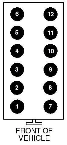
210 Appendix D Vehicles with Electronic Ignition (DIS) Fig # Cylinder Configuration # Cylinder Configuration Fig MTS 5100 Engine Analyzer Page 198
 Solarity with InfoTech Software Solarity, powered by Genisys technology, is a powerful 4-channel scope with the functionality required to analyze the most sophisticated vehicles. InfoTech Software provides
Table of Contents. General Information...1. Components...2. Connection...4
 Table of Contents General Information... Components... Connection...4 Interface of Main Unit...4 Oscilloscope...5 Multimeter...5 Voltage, Current, Resistance, Duty Cycle, Frequency and Battery Voltage...5
Cannondale Diagnostic Tool Manual
 Cannondale Diagnostic Tool Manual For vehicles (ATV & Motorcycles) equipped with the MC1000 Engine Management System Software CD P/N 971-5001983 Data Cable P/N 971-5001984 POTENTIAL HAZARD Running the
BRAKE TESTER DECELEROMETER
 OC3010_GBM_21009 BRAKE TESTER DECELEROMETER OWNER S MANUAL Version 8.++ ORBIT CONTROLS AG Zürcherstrasse 137 CH-8952 Schlieren/ZH Tel: + 41 44 730 2753 Fax: + 41 44 730 2783 info@orbitcontrols.ch www.orbitcontrols.ch
Secondary Diagnosis. By Randy Bernklau
 Secondary Diagnosis Most technicians have diagnosed secondary ignition systems using the large console-type analog scopes, but there are times when it just isn t practical to use an analyzer that is that
Caterpillar Electronic Engines Application User s Guide
 Caterpillar Electronic Engines Application User s Guide Pro-Link iq IDSC Holdings LLC retains all ownership rights to the Pro-Link iq and its documentation. The Pro-Link iq source code is a confidential
MAGPOWR Spyder-Plus-S1 Tension Control
 MAGPOWR TENSION CONTROL MAGPOWR Spyder-Plus-S1 Tension Control Instruction Manual Figure 1 EN MI 850A351 1 A COPYRIGHT All of the information herein is the exclusive proprietary property of Maxcess International,
INSTALLATION INSTRUCTIONS. Revision 3.1.1
 INSTALLATION INSTRUCTIONS Revision 3.1.1 Table of Contents INTRODUCTION... 4 INSTALLATION OVERVIEW... 5 Included Parts... 6 DEVICE WIRING... 7 Required Parts... 7 Guidelines... 7 Wiring Diagram... 8 Compatible
INSTALLATION GUIDE Table of Contents
 CT-3100 Automatic transmission remote engine starter systems. What s included..2 INSTALLATION GUIDE Table of Contents Door lock toggle mode..... 4 Notice...2 Installation points to remember. 2 Features..2
MODEL No s: PP3, PP3K
 instructions for: Power PROBE 3 12-24v MODEL No s: PP3, PP3K Thank you for purchasing a Sealey product. Manufactured to a high standard this product will, if used according to these instructions and properly
Smart Sensor Pro+ User Guide
 Smart Sensor Pro+ User Guide Important Information FCC Notice This device complies with part 15 of the FCC Rules. Operation is subject to the following two conditions: 1. This device may not cause harmful
Overview of operation modes
 Overview of operation modes There are three main operation modes available. Any of the modes can be selected at any time. The three main modes are: manual, automatic and mappable modes 1 to 4. The MapDCCD
EASE CAN! Start scanning with EASE today! EASE Diagnostics. Can any hand held scanner display data like this? Automotive Information Specialists
 EASE Diagnostics Can any hand held scanner display data like this? Automotive Information Specialists Call 1-888-366-EASE Web www.obd2.com (We didn t think so) For more information contact EASE CAN! Start
USING SCAN TOOL MEMORY
 Table of Contents SAFETY PRECAUTIONS SAFETY FIRST!... 1 BATTERY REPLACEMENT... 6 SCAN TOOL CONTROLS CONTROLS AND INDICATORS... 3 DISPLAY FUNCTIONS... 4 USING THE SCAN TOOL CODE RETRIEVAL PROCEDURE... 7
IVTM Installation Manual
 Integrated Vehicle Tire Pressure Monitoring IVTM Installation Manual 2nd edition Copyright WABCO 2006 Vehicle Control Systems An American Standard Company The right of amendment is reserved Version 002/06.06(us)
CPi. CoiL PACK IGNiTioN FOR AViATiON. For 4,6 and 8 cylinder 4 stroke applications. Please read the entire manual before beginning installation.
 1 CPi CoiL PACK IGNiTioN FOR AViATiON Coil pack (4 cylinder) Coil pack (6 cylinder) For 4,6 and 8 cylinder 4 stroke applications. Please read the entire manual before beginning installation. Software version
MoistureMatch A next generation grain tester
 MoistureMatch A next generation grain tester A next generation moisture tester incorporating new and unique technology. Finally, a portable tester that will more accurately match and track with the commercial
NexSysLink. Operation Manual. NMEA 2000 SAE J1939 Indmar Engines. CAN Instruments Product Family
 NexSysLink CAN Instruments Product Family Operation Manual NMEA 2000 SAE J1939 Indmar Engines Contact Beede Beede Electrical Instrument Company, Inc. 88 Village Street Penacook, NH 03303 (603) 753-6362
with lcd display 12-42v
 instructions for: AUTO PROBE with lcd display 12-42v MODEL No: PP7 Thank you for purchasing a Sealey product. Manufactured to a high standard this product will, if used according to these instructions
Table of Contents. 5. Warranty and Service...29
 Table of Contents 1. Safety Precautions and Warnings...2 2. General Information 2.1 On-Board-Diagnostics (OBD) II......3 2.2 Diagnostic Trouble Codes (DTCs) 3 2.3 Location of the Data Link Connector (DLC)
SB-300 Operator s Manual
 Test Equipment SB-300 Operator s Manual 20 Hand Held-Accuracy with a 40 Amp Load The SB-300 is a hand-held tester that is the auto industry s answer to portability in a professionally accurate battery
EXCELSIOR-HENDERSON MOTORCYCLE MANUFACTURING COMPANY 805 HANLON DRIVE BELLE PLAINE, MINNESOTA TELE: /FAX:
 All text, photographs, and illustrations in this handbook are based on the most current product information available at the time of publication. Product improvements or other changes may result in differences
SAFETY PRECAUTIONS Warning: Read and understand all instructions in this manual. Use appropriate personal safety equipment including hearing and eye p
 SAFETY PRECAUTIONS Warning: Read and understand all instructions in this manual. Use appropriate personal safety equipment including hearing and eye protections when using the scanner in or near the vehicle
SUZUKI DIAGNOSIS SYSTEM OPERATION MANUAL
 SUZUKI DIAGNOSIS SYSTEM OPERATION MANUAL Specifications and functions of Suzuki Diagnosis System (1) The system diagnoses troubles by communicating with the onboard computer by means of the specially designed
Do isolate the power supply from other high power systems such as Stereos and Alarms
 Thank you for purchasing a Smart Ride Air Management System, AIRBAGIT.COM s premier flagship product. This system will meet all of your custom and utility needs and will provide you years of trouble free
Model 2100 Installation Guide
 Model 2100 Installation Guide 2001 Directed Electronics, Inc. Vista, CA N2100 4-01 Rev. N/C 1.1 table of contents What Is Included..................... 2 Wiring Quick Reference Guide............ 3 Primary
User s Manual XOB15091 OBD II / EOBD CODE READER. All Rights Reserved. Warranty and Service
 5. Warranty and Service 5.1 Limited One Year Warranty The manufacturer/supplier warranty provided to customers for this product will be free from all defects in materials and workmanship for a period of
))) FirstLook. User's Guide. FirstLook Automotive Engine Diagnostic Sensor "The Pulse of Your Engine" Model ADS ES 100.
)) FirstLook. User's Guide. FirstLook Automotive Engine Diagnostic Sensor The Pulse of Your Engine Model ADS ES 100.") ))) FirstLook User's Guide FirstLook Automotive Engine Diagnostic Sensor "The Pulse of Your Engine" Model ADS ES 1 Table of Contents Section Page 1. Introduction 2 2. Overview 2. Theory of Operation 2.
))) FirstLook User's Guide FirstLook Automotive Engine Diagnostic Sensor "The Pulse of Your Engine" Model ADS ES 1 Table of Contents Section Page 1. Introduction 2 2. Overview 2. Theory of Operation 2.
INDEX. 1.Safety Precautions and Warnings...3
 INDEX 1.Safety Precautions and Warnings...3 2. General Information...5 2.1 On-Board Diagnostics (OBD) II... 5 2.2 Diagnostic Trouble Codes (DTCs)... 6 2.3 Location of the Data Link Connector (DLC)...7
Owner s Manual & Safety Instructions
 Owner s Manual & Safety Instructions Save This Manual Keep this manual for the safety warnings and precautions, assembly, operating, inspection, maintenance and cleaning procedures. Write the product s
Using the Gratec Gasoline software
 Using the Gratec Gasoline software The Gratec Software is a sophisticated yet user friendly program in which configures the Gratec CNG or LPG system to perform with your vehicle. Software version 2.002
TIMER INTERFACE USER MANUAL
 TIMER INTERFACE USER MANUAL Premium Efficiency Two-Speed Motor with Integrated Timer Formerly A. O. Smith Electrical Products Company A Regal Beloit Company COPYRIGHT Copyright 2011, Regal Beloit EPC,
OPERATION AND MAINTENANCE
 Table of Contents GENERAL INFORMATION INTRODUCTION... 1 Operating Specifications... 1 FEATURES... 1 SAFETY PRECAUTIONS... 2 SET-UP... 2 OPERATION AND MAINTENANCE TESTING AN IGNITION MODULE OR IGNITION
IMPORTANT SAFETY INSTRUCTIONS
 Table of Contents Safety... 2 Specifications... 3 Functions... 4 Operation... 5 Maintenance... 7 Warranty... 7 SAFETY SPECIFICATIONS OPERATION MAINTENANCE WARNING SYMBOLS AND DEFINITIONS This is the safety
2001 Dodge Durango ACCESSORIES & EQUIPMENT' 'Anti-Theft Systems - Dakota & Durango 2001 ACCESSORIES & EQUIPMENT
 DESCRIPTION VEHICLE THEFT SECURITY SYSTEM 2001 ACCESSORIES & EQUIPMENT Anti-Theft Systems - Dakota & Durango Vehicle Theft Security System (VTSS) provides perimeter protection against unauthorized use
Advanced User Manual
 Advanced User Manual Banks SpeedBrake For use with Palm Tungsten E2 2004-2005 Chevy/GMC 6.6L (LLY) Turbo-Diesel Pickup THIS MANUAL IS FOR USE WITH KITS 55419 & 55421 Gale Banks Engineering 546 Duggan Avenue
Instruction Manual R134a DIGITAL MANIFOLD
 Instruction Manual R134a DIGITAL MANIFOLD Includes Automotive Refrigerant and Oil Capacity Readings Instruction Manual R134a DIGITAL MANIFOLD Includes Automotive Refrigerant and Oil Capacity Readings SPECIAL
FM SECURITY AND REMOTE START SYSTEM
 FM SECURITY AND REMOTE START SYSTEM INSTALLATION MANUAL BEFORE INSTALLING THIS PRODUCT PLEASE READ THIS INSTALLATION MANUAL THOROUGHLY!! This system is intended for installation on vehicles equipped with
Technician Reference Manual. Digital Diagnostic Terminal Software Version 1.3. SmartCraft Systems. Printed in U.S.A.
 Technician Reference Manual Digital Diagnostic Terminal Software Version 1.3 SmartCraft Systems Printed in U.S.A. 90-881204003 1003 Note: To take full advantage of the tool, you should be knowledgeable
Battery Management Innovation. For 12-volt automotive starting batteries and starting/charging systems INSTRUCTION MANUAL
 Battery Management Innovation For 12-volt automotive starting batteries and starting/charging systems INSTRUCTION MANUAL ! CAUTION Because of the possibility of personal injury, always use extreme caution
M-9603-SVT mm Cold Air Kit w/premium Calibration INSTALLATION INSTRUCTIONS
 Please contact the Tech Line for the most current instruction information (800) 367-3788.!!! PLEASE READ THE FOLLOWING INSTRUCTIONS CAREFULLY PRIOR TO INSTALLATION!!! OVERVIEW: This kit is designed for
Preparing and programming of ESGI 2 LPG supply system manual
 Preparing and programming of ESGI 2 LPG supply system manual Part II Instruction of preparing and programming the ESGI system 1 Technical data of the central unit Vs Power supply voltage 0...16V V i_an
Prop-Tech Vacuum Analyzer
 Electronic Carburettor / Injector Balancing Tool 1. WARNING THIS PRODUCT IS A PROFESSIONAL TOOL WHICH SHOULD ONLY BE OPERATED BY A COMPETENT TRAINED TECHNICIAN AND ONLY FOR THE PURPOSE WHICH IT WAS DESIGNED
GPS Steering System Installation Manual
 GPS Steering System Installation Manual Supported Vehicles Challenger Massey Ferguson AGCO MT-645C, MT-645D MF-8650 DT-205B MT-655C, MT-655D MF-8660 DT-225B MT-665C, MT-665D MF-8670 DT-250B MT-675C, MT-675D
Lingenfelter NCC-002 Nitrous Control Center Quick Setup Guide
 Introduction: Lingenfelter NCC-002 Nitrous Control Center Quick Setup Guide The NCC-002 is capable of controlling two stages of progressive nitrous and fuel. If the NCC-002 is configured only for nitrous,
Service Bulletin Immobilizer System (Type 6) (Supersedes , dated February 20, 2009; see REVISION SUMMARY) February 22, 2013
 (Supersedes , dated February 20, 2009; see REVISION SUMMARY) February 22, 2013") Service Bulletin 06-033 Applies To: 2007-09 MDX ALL 2007-12 RDX ALL February 22, 2013 Immobilizer System (Type 6) (Supersedes 06-033, dated February 20, 2009; see REVISION SUMMARY) REVISION SUMMARY This
Service Bulletin 06-033 Applies To: 2007-09 MDX ALL 2007-12 RDX ALL February 22, 2013 Immobilizer System (Type 6) (Supersedes 06-033, dated February 20, 2009; see REVISION SUMMARY) REVISION SUMMARY This
AUTOMOTIVE IGNITION SYSTEMS
 AUTOMOTIVE IGNITION SYSTEMS ABSTRACT This report describes the differences and similarities between a 1964 Mustang traditional ignition system and that of my 2014 Jeep. To help you understand the process
SmarTire TPMS Maintenance Hand Tool. Revision User Manual
 SmarTire TPMS Maintenance Hand Tool Revision 1.04 User Manual Page 2 Table of Contents FCC Compliance Label... 4 User Interface Illustration... 4 Introduction... 5 Testing Tire Sensors... 5 Main Menu...
Issue 2.0 December EPAS Midi User Manual EPAS35
 Issue 2.0 December 2017 EPAS Midi EPAS35 CONTENTS 1 Introduction 4 1.1 What is EPAS Desktop Pro? 4 1.2 About This Manual 4 1.3 Typographical Conventions 5 1.4 Getting Technical Support 5 2 Getting Started
Selected excerpts from the book: Lab Scopes: Introductory & Advanced. Steven McAfee
 Selected excerpts from the book: Lab Scopes: Introductory & Advanced Steven McAfee 1. 2. 3. 4. 5. 6. Excerpt from Chapter 1 Lab Scopes How do they work? (page 6) Excerpt from Chapter 3 Pattern Recognition
GPS AutoSteer System Installation Manual
 GPS AutoSteer System Installation Manual Supported Vehicles Case IH Combines 7010 7120 8010 8120 AFX 8010 9120 PN: 602-0283-01-A LEGAL DISCLAIMER Note: Read and follow ALL instructions in this manual carefully
SAFETY PRECAUTIONS SAFETY FIRST!... 1 ABOUT THE CODE READER CONTROLS AND INDICATORS... 3 DISPLAY FUNCTIONS... 4
 Table of Contents SAFETY PRECAUTIONS SAFETY FIRST!... 1 ABOUT THE CODE READER CONTROLS AND INDICATORS... 3 DISPLAY FUNCTIONS... 4 USING THE CODE READER CODE RETRIEVAL PROCEDURE... 7 VIEWING ABS DTCs...
MAXIMIZER-II Progressive Nitrous Controller INSTALLATION AND USER MANUAL. MAXIMIZER-II rev A
 MAXIMIZER-II Progressive Nitrous Controller INSTALLATION AND USER MANUAL i Table of Contents Page 1. Installation Overview...1 1.1 MAXIMIZER-II Power Input...1 1.2 SOLENOID DRIVER Ground...1 1.3 Arming
OPERATING INSTRUCTIONS
 RS2-G3 ONE BUTTON 2-WAY REMOTE START SYSTEM OPERATING INSTRUCTIONS CONGRATULATIONS on your choice of a Cool Start Remote Engine Starter and Keyless Entry with DP Technology by Crimestopper Security Products
SmarTire TPMS Maintenance Hand Tool. Revision User Manual
 SmarTire TPMS Maintenance Hand Tool Revision 1.03 User Manual Page 2 Table of Contents FCC Compliance Label...4 User Interface Illustration...4 Introduction...5 Testing Tire Sensors...5 Main Menu...6 Main
ITCEMS950 Idle Timer Controller - Engine Monitor Shutdown Isuzu NPR 6.0L Gasoline Engine
 Introduction An ISO 9001:2008 Registered Company ITCEMS950 Idle Timer Controller - Engine Monitor Shutdown 2014-2016 Isuzu NPR 6.0L Gasoline Engine Contact InterMotive for additional vehicle applications
Release Notes. Release Notes Contents. Overview. New Vehicle Coverage - Summary: Version
 Release Notes Version 3.1.1.9 Release Notes Contents Overview New Vehicle Coverage Summary New Software Improvements Summary New Vehicle Coverage - Details New Software Improvements - Details Overview
Module 22 Ignition Systems - Outputs
 Module 22 Ignition Systems - Outputs Author: Grant Swaim E-mail: sureseal@nr.infi.net URL: www.tech2tech.net Phone: (336) 632-9882 Fax: (336) 632-9688 Postal Address: Tech-2-Tech Website PO Box 18443 Greensboro,
User Manual Industrial Power Storage System (ips) ips-m Series Battery System
 ips-m Series Battery System") User Manual Industrial Power Storage System (ips) ips-m Series Battery System Copyright The documentation and the software included with this product are copyrighted 2011 by Advantech Co., Ltd. All rights
User Manual Industrial Power Storage System (ips) ips-m Series Battery System Copyright The documentation and the software included with this product are copyrighted 2011 by Advantech Co., Ltd. All rights
INSTALLATION GUIDE. FCC ID NOTICE
 REV.5 RS. ADVANCED REMOTE STARTER INSTALLATION GUIDE www.security.soundstream.com FCC ID NOTICE This device complies with Part 5 of the FCC rules. Operation is subject to the following conditions:. This
Release Notes. Release Notes Contents. Overview. New Vehicle Coverage - Summary: Version
 Release Notes Version 3.1.1.9 Release Notes Contents Overview New Vehicle Coverage Summary New Software Improvements Summary New Vehicle Coverage - Details New Software Improvements - Details Overview
Super Brain 989 The Pinnacle of Performance with Power to Spare User s Manual Model Rectifier Corporation
 Super Brain 989 The Pinnacle of Performance with Power to Spare User s Manual Temperature sensor jack Sensor included Model Rectifier Corporation Please read this entire manual including all Safety Cautions,
MEGA 462 REMOTE CONTROL AUTO ALARM SYSTEM INSTALLATION & OPERATION INSTRUCTIONS WIRING DIAGRAM. White. H1 5 Pin White. H6 2 Pin White.
 MEGA 462 REMOTE CONTROL AUTO ALARM SYSTEM INSTALLATION & OPERATION INSTRUCTIONS WIRING DIAGRAM H7/1 Green : (-) 200mA Pulse H7 3 Pin H7/3 Blue : (-) 200mA Unlock White LED Indicator Valet Switch H6 2 Pin
Handout Activity: HA061
 Dynamometer HA061-2 Handout Activity: HA061 Dynamometer The dynamometer applies various loads on the engine and measures the engine s ability to move the load. There are two types of dynamometer: Engine
Dynojet Research, Inc. All Rights Reserved. Optical RPM Sensor Installation Guide.
 1993-2001 Dynojet Research, Inc. All Rights Reserved.. This manual is copyrighted by Dynojet Research, Inc., hereafter referred to as Dynojet, and all rights are reserved. This manual, as well as the software
Security and Keyless Entry Installation Guide ca 1051
 PROFESSIONAL SERIES Security and Keyless Entry Installation Guide ca 1051 ca1051 rev B. 2011 Audiovox Electronics Corporation. All rights reserved. 1 Table of Contents Before You Begin... 3 Wire Connection
GPS AutoSteer System Installation Manual
 GPS AutoSteer System Installation Manual John Deere Track Supported Models 8295RT 8320RT 8345RT PN: 602-0255-01-A LEGAL DISCLAIMER Note: Read and follow ALL instructions in this manual carefully before
SAFETY PRECAUTIONS AND WARNINGS...
 Table of Contents 1. SAFETY PRECAUTIONS AND WARNINGS... 1 2. USING THE TEST TOOL... 2 2.1 TOOL DESCRIPTION... 2 2.2 SPECIFICATIONS... 3 2.3 ACCESSORIES INCLUDED... 3 2.4 GENERAL DESCRIPTION... 4 2.5 POWER...
B-RAD Select USER MANUAL TABLE OF CONTENTS
 TABLE OF CONTENTS TABLE OF CONTENTS... 1 MANUAL REVISION HISTORY... 2 IMPORTANT SAFETY NOTICE... 3 1.0 General Information... 5 1.1 System Components... 5 1.2 Specifications... 5 1.2.1 Torque Ranges...
Hand Pump Accessories
 Hand Pump Accessories MVA6010 Fluid Transfer Accessory Kit Model MVA6010 extends the applications of Mityvac hand vacuum/pressure pumps to include dispensing and evacuating fluids, and pressure brake bleeding.
Superchips Model 2704 MAX MicroTuner GM Trucks with 6.6L Duramax Diesel Engines Vehicle Programming Instructions
 Page 1 of 12 Form 0137D 11/30/2004 Superchips Inc. Superchips Model 2704 MAX MicroTuner 2004-2005 GM Trucks with 6.6L Duramax Diesel Engines Vehicle Programming Instructions PLEASE READ THIS ENTIRE INSTRUCTION
User s Manual ENGINE IGNITION ANALYZER. General Technologies Corp.
 User s Manual ENGINE IGNITION ANALYZER General Technologies Corp. Table of Contents 1. Safety Rules Page 1 2. Technical Specifications Page 2 2.1 General specifications Page 2 2.2 Electrical specifications
A U T O M A T I C T R A N S M I S S I O N M U L T I - C H A N N E L T W O - W A Y L C D R E M O T E S T A R T E R AS-2510 TW.
 A U T O M A T I C T R A N S M I S S I O N M U L T I - C H A N N E L T W O - W A Y L C D R E M O T E S T A R T E R S Y S T E M AS-2510 TW User Guide Transmitter Part Number and Module Serial Number...2
Current Clamp, clamped around the starter wire. Pico Scope. Relative Compression Test on a 2007 Honda Accord SE 4CYL
 P a g e 1 Relative Compression Test on a 2007 Honda Accord SE 4CYL A relative compression test is performed by monitoring the electrical current to the starter while cranking the engine over. The amount
Orica Seismic Electronic Initiation System OSEIS TESTER. Manual
 Orica Seismic Electronic Initiation System OSEIS TESTER Manual Version 2.00a, November 2006 Overview Oseis System... 2 1. Oseis Detonator, Tester and accessories... 3 1.1 Oseis electronic detonator...
REC-11+ REMOTE RECEIVER UNIT
 Resetting The Programmable Features The installer may quickly and easily return all 17 programmable features back to the factory settings. Changing individual features were explained in detail in the previous
MDX-300 Series. For 12-volt automotive starting batteries and starting/charging systems INSTRUCTION MANUAL
 For 12-volt automotive starting batteries and starting/charging systems INSTRUCTION MANUAL Blank page Contents Caution... 4 Capabilities... 4 Display and Keypad... 4 Preparations Before the Test... 6 Connecting
Model: AEM14 Analog Engine Monitor
 Model: AEM14 Analog Engine Monitor Installation and Setup Manual Version 1 Table of Contents Monitor Overview DMK Engine Monitor Kit Section 1: Initial Setup 1.1 Internal Settings Switches Figure 1. AEM14
1998 ENGINE PERFORMANCE. General Motors Corp. - Basic Diagnostic Procedures - 5.7L
 INTRODUCTION 1998 ENGINE PERFORMANCE General Motors Corp. - Basic Diagnostic Procedures - 5.7L The following diagnostic steps will help prevent overlooking a simple problem. This is also where to begin
SCHNITZ MOTORSPORTS USER MANUAL AND INSTALLATION GUIDE PRO-MOD BATTERY VOLTS DIAGNOSTICS NOS PULSE FREQUENCY NOS DELAY TIME IN SECONDS
 SCHNITZ MOTORSPORTS DSC-CS "PRO-MOD" IGNITION CONTROLLER USER MANUAL AND INSTALLATION GUIDE COIL, (OPTIONAL) GA YELLOW, COIL, NEGATIVE GA WHITE, GA BLACK, SHIFT LIGHT +V OUTPUT PAGE 0 NOS ACTIVATION INPUT
Table of Contents 1. INTRODUCTION GENERAL INFORMATION-ABOUT OBDII/EOBD PRODUCT DESCRIPTIONS OPERATIONS...11
 Table of Contents 1. INTRODUCTION...1 2. GENERAL INFORMATION-ABOUT OBDII/EOBD...1 2.1 ON-BOARD DIAGNOSTICS (OBD) II...1 2.2 DIAGNOSTIC TROUBLE CODES (DTCS)...2 2.3 LOCATION OF THE DATA LINK CONNECTOR (DLC)...3
TWO-WAY LED MANUAL / AUTOMATIC TRANSMISSION REMOTE STARTER. User Guide WARNING
 TWO-WAY LED MANUAL / AUTOMATIC TRANSMISSION REMOTE STARTER User Guide WARNING It is the responsibility of the vehicle operator to ensure their vehicle is parked in a safe and responsible manner. 1. a)
TWO-WAY LED AUTOMATIC TRANSMISSION REMOTE STARTER. User Guide WARNING
 TWO-WAY LED AUTOMATIC TRANSMISSION REMOTE STARTER User Guide WARNING It is the responsibility of the vehicle operator to ensure their vehicle is parked in a safe and responsible manner. 1. When leaving
MEGA WAY LCD 4-CHANNEL CAR ALARM SECURITY SYSTEM. Installation Manual MEGATRONIX CALIFORNIA, USA MEGA 2500 INSTALL 1
 MEGA 2500 2-WAY LCD 4-CHANNEL CAR ALARM SECURITY SYSTEM Installation Manual MEGATRONI CALIFORNIA, USA MEGA 2500 INSTALL 1 MEGA 2500 INSTALL 2 INSTALLATION DIAGRAM H8: 10 Pin White Mini Connector H8 10
Holden VZ 3.6L ECU & Powertrain Interface Module Linking Instructions
 Holden VZ 3.6L 2004-2006 ECU & Powertrain Interface Module Linking Instructions Contents Page In Brief PIM Replacement, ECM Replacement 2 VZ 3.6L System Overview 3 PIM Functions 4 PIM Location 4 ECM Functions
KE 680 DELUXE 4-CHANNEL KEYLESS ENTRY SYSTEM DOOR LOCK RELAYS ON-BOARD. Installation And Operation Manual MEGATRONIX CALIFORNIA, U.S.A.
 KE 680 DELUE 4-CHANNEL KEYLESS ENTRY SYSTEM DOOR LOCK RELAYS ON-BOARD Installation And Operation Manual MEGATRONI CALIFORNIA, U.S.A. KE 680 1 INSTALLATION DIAGRAM H8: 10 Pin White Mini Connector H8 10
F - BASIC TESTING Nissan 240SX INTRODUCTION VISUAL INSPECTION COMPRESSION CHECK EXHAUST SYSTEM BACKPRESSURE CHECK
 F - BASIC TESTING 1990 Nissan 240SX 1990 ENGINE PERFORMANCE Nissan - Basic Diagnostic Procedures Nissan; Axxess, Maxima, Pathfinder, Pickup, Pulsar NX, Sentra, Stanza, Van, 240SX, 300ZX INTRODUCTION The
MIC4 IGNITION CONTROLLER
 MIC4 IGNITION CONTROLLER MIC4 MOTORTECH IGNITION CONTROLLER Try the alternative. Call the nearest MOTORTECH sales partner for more information. REV.02/2015 MIC4 IGNITION CONTROLLER The economically attractive
Heavy-Duty Battery and Electrical System Diagnostic Tester
 Sabre Heavy-Duty Heavy-Duty Battery and Electrical System Diagnostic Tester Heavy-duty for 24-volt battery and electrical systems Diagnoses battery packs in series, parallel, or series/parallel Test AGM/gel
Version 1.0 Copyright DC-RPM-iBox User Manual
 Version 1.0 Copyright 2012 DC-RPM-iBox User Manual D Y N O C O M S E R I E S C H A S S I S D Y N A M O M E T E R S DC-RPM-iBox User Manual Copyright This manual is copyrighted by Dynocom Industries, Inc.,
SERVICE BULLETIN. Legacy D* Outback D* Impreza 4-Door D* Impreza 5-Door XV Crosstrek D* Forester E* BRZ D*607924
 ATTENTION: GENERAL MANAGER q PARTS MANAGER q CLAIMS PERSONNEL q SERVICE MANAGER q IMPORTANT - All Service Personnel Should Read and Initial in the boxes provided, right. SERVICE BULLETIN APPLICABILITY:
CPU-95 ADVANCED DIGITAL IGNITION SYSTEM FOR INDUSTRIAL ENGINES
 New Backward-Compatible Enhanced CPU-95 Display Now Available CPU-95 ADVANCED DIGITAL IGNITION SYSTEM FOR INDUSTRIAL ENGINES Microprocessor-based, crankshaft referenced digital ignition system for medium-sized
GENERAL MOTORS SERVICE PARTS OPERATION 6200 Grand Pointe Drive, Grand Blanc, MI 48439
 LS IGNITION CONTROLLER 19355418 Ignition Control for Carbureted LS Series Engines (24x Crankshaft Index/1x Camshaft Index, 58x Crankshaft Index/4x Camshaft Index) Parts Included Quantity Ignition Controller
QUICK START GUIDE 199R10546
 QUICK START GUIDE 199R10546 1.0 Overview This contains detailed information on how to use Holley EFI software and perform tuning that is included within the software itself. Once you load the software,
PowerSTAR PS-2024-D. Maximum Power Point Tracking Solar Regulator. w w w. r o c s o l i d. c o m. a u. Contents
 w w w. r o c s o l i d. c o m. a u PowerSTAR PS-2024-D Maximum Power Point Tracking Solar Regulator Contents 1 Quick Start Guide... 2 2 Specifications... 3 2.1 General Operation... 3 2.2 Absolute Maximum
2009 Hickok Inc. All rights reserved.
 User Guide FPT2600-EX1 I/M Handheld Fuel Cap Test System No part of this manual may be reproduced or transmitted in any form or by any means, electronic or mechanical, without written permission from Hickok.
INSTALLATION MANUAL. Fendt VarioGuide Ready COM 3 Supported Models PN REV A
 INSTALLATION MANUAL Fendt VarioGuide Ready COM 3 Supported Models 922 924 927 930 933 936 PN 602-0264-02 REV A LEGAL DISCLAIMER Note: Read and follow ALL instructions in this manual carefully before installing
TWO-WAY LED MANUAL TRANSMISSION REMOTE STARTER. User Guide WARNING
 TWO-WAY LED MANUAL TRANSMISSION REMOTE STARTER User Guide WARNING It is the responsibility of the vehicle operator to ensure their vehicle is parked in a safe and responsible manner. 1. When leaving the
OMEM200 Tuning Manual 3v Series ECU. Tuning Manual OMEM200.
 200 Series ECU Tuning Manual OMEM200 www.omextechnology.com 0 1 Introduction... 3 1.1 What this manual covers... 3 1.2 Notation Used in This Manual... 3 2 Software... 4 3 Sensor Setup... 5 3.1 Throttle
Model 2000 Installation Guide
 Model 2000 Installation Guide 2001 Directed Electronics, Inc. Vista, CA N2000 8-01 Rev. N/C 1.0 table of contents What Is Included..................... 2 Primary Harness (H1), 12-Pin Connector..... 3 Door