Orica Seismic Electronic Initiation System OSEIS TESTER. Manual
|
|
|
- Emery Valentine Garrison
- 5 years ago
- Views:
Transcription

1 Orica Seismic Electronic Initiation System OSEIS TESTER Manual Version 2.00a, November 2006
2 Overview Oseis System Oseis Detonator, Tester and accessories Oseis electronic detonator Oseis Tester... 4 Technical data Accessories Basic functions of Tester Flow chart of menus Operation keys Display Switch on/off Charging Functions of the main menu Setup menu Logging Mode Manual (M) Manual (MSP) with shotpoint information Backlighting Data transfer Print Copy memory Seismic-i Erase memory Log detonators Logging and testing using manual mode Logging and testing using manual mode with shotpoint information Warning messages and trouble shooting No log Leakage current Faulty detonator Incompatible detonator Relog System limits Test single detonator No reply Data error View detonators Measure leakage Error reports and warning messages During operation Battery warning During start up routine Battery discharged Data error Hardware error X
3 Overview Oseis System The Orica Seismic Electronic Initiating System is designed to provide accurate, secure and reliable initiation of explosives used in seismic surveys. The Oseis system consists of digital detonators and control equipment (Tester and Shooter with trigger cable). Oseis electronic detonator Oseis detonators are capable of two-way communication, highly accurate and programmable. Each detonator has a unique factory assigned identity number, which is written to the detonator microchip. This is the basis for full communication between detonators and control equipment. The unique detonator ID is printed on a flag tag and allows inventory traceabiltiy. Oseis detonators have protection structures in the electronic circuitry, which give a high level of protection against stray currents, over-voltage, static electricity and electromagnetic radiation. Oseis detonators can only be programmed and fired by Oseis Shooters, which provide the required firing energy and digital information. Oseis Tester The Oseis Tester is a handheld device used for testing of Oseis detonators and for recording the unique detonator ID and the corresponding shotpoint identifier (line and shot point number). Typically this is done when the shotpoint is loaded by the drill crew. The Tester complies with the principle of Inherent Safety. This means that the Tester is unable to fire Oseis detonators even if the Tester and the Detonator would develop faults. The Tester memory can save data for up to 300 shotpoints. The user is able to review the data stored in the Oseis Tester and to upload the data to a PC based software program called seismic-i. Oseis Shooter The Oseis Shooter is a handheld device used for firing of Oseis detonators and for recording of data. To fire the shot, the Shooter is connected to a conventional shooting system via the trigger cable. The Shooter itself is connected via the firing cable to the Oseis electronic detonator(s). Oseis Shooters are protected by a personalised identification number (PIN) to prevent use by unauthorised personnel. When the Shooter has programmed and armed an Oseis detonator, it is ready to fire and waiting for the trigger signal, a high voltage capacitor discharge impulse from a conventional radio controlled seismic shooting system. The Shooter issues the ultimate firing command upon receipt of the high voltage impulse. The delay time between receipt of the trigger signal to the detonator firing has an offset of 20 ms. The Shooter memory can save data for up to 1000 shotpoints. The user is able to review the data stored in the Shooter and to upload or download the data to a PC based software program called seismic-i. 2
4 1. Oseis Detonator, Tester and accessories 1.1 Oseis electronic detonator Programmable electronic detonator from 0 to 5000 ms in 0.1 ms increments. Any delay time has an offset of 20 ms to the receipt of the high voltage trigger pulse from the radio controlled firing panel. The timing accuracy is: 0 ms ms: 20 ms offset + delay time ± 0.1 ms, ms ms: 20 ms offset + delay time ± 0.01% of delay time. A delay time can only be assigned in combination with seismic-i. Water tightness: 10 bars for 7 days, 5 bars for 28 days. Tensile strength of legwires: > 180 N. Legwire length: 3, 4, 6, 7, 10, 15, 20, 30 and 50 m. Unique detonator ID printed on flag tag. Twinned steel legwire with an abrasion resistant orange polymer. Output is equivalent to a #8 strength detonator. 3
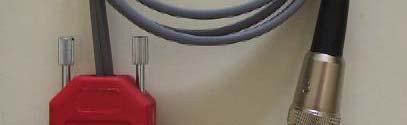
5 1.2 Oseis Tester Oseis Tester 2 Yellow carry case 3 Ring terminals (removable) 4 Charger mains power. Compatible with Oseis Shooter. Technical data Maximum number of Oseis electronic detonators per Tester: 300. Maximum resistance of firing cable is 100 Ohms under ideal conditions. Operating temperature: -20 C C. Storage temperature: -25 C C. Water and shock resistant (IP65). Operating time without backlighting and leakage current approximately 10 hours at 20 C. 4


6 1.3 Accessories Volts car charger. Compatible with Tester and Shooter. 2 Copy cable. Tester to Tester. 3 Download/Upload cable to serial port of PC or Laptop. Compatible with Tester and Shooter. 5
7 2. Basic functions of Tester 2.1 Flow chart of menus Erase memory Data transfer Backlighting Logging mode Seismic-i Copy memory Print Manual Manual SP Setup menu Measure leakage View detonators MAIN MENU on Test single det Log detonators 2.2 Operation keys For operating the Tester has six keys. The main functions are: (1) - Change position when entering SP info - Special function (Test single det, View detonators) - Display of battery status (Main Menu) (2) - Increase value - Scroll up (3) - Decrease value - Scroll down (4) - Choice of displayed menu - Confirmation (5) - Change position when entering SP info - Switch off (hold for 2 seconds) - Exit to main menu (6) +/- - Switch on (hold for 2 seconds) By pressing and holding keys and the scroll rate for incrementing or decrementing values is increased. 6

8 2.3 Display For interaction with the Tester a LCD-screen with 2 lines and 16 characters per line is provided. With the help of the LCD-screen the user is directed to the menu of choice. Furthermore acoustic signals, including warning signals, are given during certain functions of the Tester. 2.4 Switch on/off Switch on The Tester is switched on by pressing key +/- for approximately 2 seconds. After switching on the firmware version number (I) is displayed on the screen. Next a self test is carried out (II), during which the status of the battery (0-100%) and the serial number are displayed (III). Finally the Tester defaults to the main menu (IV). (I) OSEI S T EST ER V e r s i o n x. x x (II) OSEI S T EST ER S e l f - T e s t (III) B a t t e r y = x x x % T E S T E R S N : X X X X X (IV) * * MA I N ME NU * * L o g d e t o n a t o r s If the Tester fails the self test an error message will appear indicating the nature of the failure followed by the automatic shut down of the Tester (see Error reports and warning messages). During the self test the backlighting is always turned on. If the backlighting function is turned off, the backlighting turns off automatically, once the self test is completed. Switch off The Tester is switched off by pressing key for approximately 2 seconds in the main menu. The message Tester is shutting down is displayed in the screen, when the Tester is switched off. Note: To save battery life the Tester switches off automatically, if the operating keys are not used for 15 minutes. 7
9 2.5 Charging The batteries are recharged via a cable attached to the multi pin port located on the front of the Tester from any mains power source with the delivered charger (90-230V, 40-60Hz) or from a 12 V source using the optional car charger. During recharging the battery icon flashes. When the battery is fully charged the icon is steadily lit. It is recommended to store the Tester connected to the charger (trickle charge). This guarantees that the Tester is always ready for use. Dependent on the battery status it may take up to 3 hours to recharge the Tester. Note: Before the first use the Tester has to be charged for 3 hours. 8
10 3. Functions of the main menu In the main menu the Tester firmware version and the battery status can be checked, simply by pressing key : V e r s i o n x. x x B a t t e r y = x x x % 3.1 Setup menu After switching on the Tester, it automatically defaults to the main menu. With the aid of keys or the operator can select the Setup menu. The screen shows: * * MAI N ME NU * * S e t u p M e n u By confirmation with key the Setup Menu is chosen. In this menu the options Logging mode, Backlighting, Data transfer or Erase memory are available, which can be selected with keys or. The display shows one of the following screens: * SETUP MENU * L o g g i n g m o d e * SETUP MENU * B a c k l i g h t i n g * SETUP MENU * Da t a t r a ns f e r * SETUP MENU * E r a s e m e m o r y Each option can be chosen by pressing key Logging Mode The following Logging modes are available: - Manual (M): In manual mode the Tester automatically logs each detonator upon connection and displays the unique ID, the detonator status and current leakage level. Upon confirmation the data is saved to the permanent Tester memory. When the option confirmation off is selected the data is automatically written to the permanent memory after a display time of 3 seconds without confirmation. 9
11 - Manual Shotpoint information (MSP): This mode allows to enter shotpoint information for each hole. After entering the line and shotpoint data, the Tester automatically logs each detonator upon connection and displays the unique ID, the detonator status and current leakage level. The data is then saved along with the SPI to the permanent Tester memory. Different options for entering the shotpoint data are available. The options and the associated input are illustrated in the following picture. Logging modes and user settings Manual (M) Input Confirmation ON / OFF Manual SP (MSP) Input SP Auto Inc OFF / UP / DOWN Confirmation ON / OFF After the choice of the Logging mode one of the following options can be selected with keys or : * L O G G I N G M O D E * M: Ma nua l * L O G G I N G M O D E * MS P : Ma n u a l - S P By pressing key the displayed option is confirmed. Note: The logging modes are incompatible. The memory must be cleared for a change of the logging mode: Manual (M) Upon connection of the detonator to the Tester, the detonator is automatically logged and tested. The unique ID, the detonator status and the current leakage value are displayed in the screen. The user can select, if the data are automatically saved after a display time of 3 seconds (confirmation off), or if the displayed data must be confirmed (confirmation on). + C O N F I R M A T I O N + O f f O n Confirmation is switched off or on, simply by pressing key or respectively. Next the Tester defaults to the main menu. 10
12 Manual (MSP) with shotpoint information OSEIS TESTER The user can select, if the shotpoint number is automatically increased (up) by one, decreased (down) by one or if the auto incrementing is switched off. + SHOTPOI NT I NC + AUTO: OFF The option (off, up, down) can be selected with the and key and subsequent confirmation. The default option for the auto increment is off. Following, the user can select, if the data are automatically saved after a display time of 3 seconds (confirmation off), or if the displayed data must be confirmed (confirmation on). + C O N F I R M A T I O N + O f f O n Backlighting After selection of the Backlighting option the following screen appears: + BACKL I GHT I NG + O f f O n The user can turn the backlighting off or on, simply by pressing key or respectively. Next the Tester defaults to the main menu. When the screen and key backlighting has been activated and the keys are not used for more than one minute the backlighting switches off automatically to conserve power. With the next strike of any key the backlighting turns on again. Note: It is recommended to turn off the backlighting unless it is necessary for operating the Tester Data transfer Print The print option enables the operator to print the current logging data list from the Tester memory. The header of the printout shows the Tester firmware version and serial number and the total number of logged and tested detonators. The following data lists for each detonator the unique ID, the current status and the current leakage value. If the logging mode Manual SP was used, the shotpoint information is additionally listed for each detonator. The data list can be printed into a textfile using a hyperterminal. A download cable is required for connection to the serial port of a PC or laptop. 11
13 Da t a t r a ns f e r P r i n t After selection and confirmation of the Print option the following screen appears: Da t a t r a ns f e r After printing the Tester defaults to the main menu Copy memory For a transfer of all data saved in the memory of one Tester to any other Tester both Testers must be set to the following screen: Da t a t r a ns f e r Cop y me mo r y Both Testers must be connected with a copy cable. The active Tester, which is operated, will copy the memory of the attached Tester. After confirmation of the Copy memory option the following screens appear: Da t a t r a ns f e r Da t a t r a ns f e r Ok The successful data transfer must be confirmed. On confirmation the active Tester defaults to the main menu. The other Tester is shut down automatically. The Copy memory function also enables a data upload to the dedicated software Seismic capture. The Tester must be set to the Copy memory screen when the upload function in Seismic capture software is used Seismic-i For an upload of data from the Tester to the PC based Seismic-i software after logging the Tester must be set to the following screen: Da t a t r a ns f e r S e i s m i c - i Next the Tester must be connected to the serial port of the laptop or PC with a download cable. 12
14 After confirmation of the upload option in Seismic-i the following screen appears: Da t a t r a ns f e r Da t a t r a ns f e r Ok The successful data transfer must be confirmed. On confirmation the Tester defaults to the main menu Erase memory To clear the Tester memory the Erase memory function is available. After selection the user will be prompted with the following warning messages: E r a s e m e m o r y? No YES Pressing of the confirmation key is accompanied by a beep: A r e y o u s u r e? No Ye S Upon confirmation with key main menu. the memory is cleared and the Tester returns to the 3.2 Log detonators For logging and testing of an Oseis detonator the legwires must be connected to the Tester output terminals, while the Tester is in logging mode, i.e. the screen must show logging det# xxx. Either wire may be inserted into either terminal, but only one wire per terminal. In cold weather the optional ring terminals may be helpful for testing the detonators. If the connection is good and the detonator responds to the Tester, the operator is reassured by an acoustic signal (3 short beeps). The Tester reads the detonator ID and also automatically carries out a leakage current measurement. The detonator number, the unique ID, status information and current leakage value are then displayed on the screen. Another beep is given when the data is accepted and saved to the memory of the Tester. The Tester offers different logging modes, which can be selected in the setup menu. To commence detonator logging, the user must select the main menu Log detonators: * * MAI N ME NU * * L o g d e t o n a t o r s 13
15 3.2.1 Logging and testing using manual mode OSEIS TESTER After selection of the Log detonators menu the first screen displays the user setup information (assuming that no detonator has been logged previously and the memory is cleared): MODE : M CONF : x x De t s l ogge d : 0 The upper line displays the Logging mode: Manual (Mode: M) and the confirmation option ( on: ++ or off: -- ). The lower line shows the number of logged and tested detonators saved to the memory (Dets logged: 0). Pressing key will accept the displayed information and advance to the first logging detonator screen: L o g g i n g d e t # 1 I L = x x. x m A During detonator logging and testing the Tester continuously measures the current leakage. The result of the continuous current leakage measurement is displayed in the lower line of the screen. Now the first detonator can be connected. Successful logging and testing is indicated by three short audible beeps: D e t # : X X X X X X De t OK, x x. x ma The Tester displays the detonator number in the memory (det# 1), the unique ID (e.g. 6F0BD2), the detonator status (Det OK) and the current leakage (xx.x ma). Upon confirmation with key an audible beep is given, the data is saved to the memory and the next detonator can be logged and tested. L o g g i n g d e t # 2 I L = x x. x m A Key exits to the main menu. If the Confirmation off option has been selected in the setup menu, the detonator information is displayed for 3 seconds, once a detonator has been logged and tested successfully, before the data is saved and the screen is automatically advanced to the next logging detonator screen Logging and testing using manual mode with shotpoint information After selection of the Log detonators menu the first screen displays the user setup information (assuming that no detonator has been logged previously and the memory is cleared): MODE : MSP CONF : + + De t s l ogge d : 0 14
16 The upper line displays the Logging mode: Manual with Shot Point Identifier (Mode: MSP) and the confirmation option ( on: ++ or off: -- ). The lower line shows the number of logged and tested detonators saved to the memory (Dets logged: 0). Pressing key will accept the displayed information and advance to the first shotpoint identifier screen: L i n e S h o t p o i n t The line number (4 digits) and shotpoint identifier (4 digits and decimal) of the first shotpoint can be entered with the up or down key, the cursor position can be changed with keys (next right) and (back, next left). If the cursor is positioned on the decimal position, the step width is 0.1. In the example the first shotpoint identifier is L i n e S h o t p o i n t Upon confirmation with key, the Tester advances to the logging detonator screen: L o g g i n g d e t # 1 I L = x x. x m A During detonator logging and testing the Tester continuously measures the current leakage. The result of the continuous current leakage measurement is displayed in the lower line of the screen. Now the first detonator can be connected. Successful logging and testing is indicated by three short audible beeps: D e t # : X X X X X X De t OK, x x. x ma The Tester displays the detonator number in the memory (det# 1), the unique ID (e.g. 7A0ED2), the detonator status information (Det OK) and the current leakage (xx.x ma). Upon confirmation with key a beep is given and the data is saved to the memory. Now the next shotpoint identifier can be entered. The Tester automatically proposes the shotpoint identifier of the last shotpoint, if the shotpoint auto increment option is switched off. L i n e S h o t p o i n t With the up or down key (increase or decrease value) and the and key (cursor position: next right or next left) the shotpoint information can easily be changed. Each change must be confirmed with key. 15
17 If the shotpoint auto increment option is up, then the shotpoint number is automatically counted up (e.g. in this case to 644.0). If the shotpoint auto increment option is down, then the shotpoint number is automatically counted down (e.g. in this case to 642.0). After manual setting of the shotpoint information (e.g. to 644): L i n e S h o t p o i n t and confirmation with key the next detonator can be logged and tested. L o g g i n g d e t # 2 I L = x x. x m A Key exits to the main menu on the logging screen. On the shotpoint identifier information screen the key serves to move the cursor. Therefore the shotpoint information screen must be confirmed prior to exiting to the main menu Warning messages and trouble shooting No log The screen remains unchanged Logging det# xxx and no audible beep. If a detonator is not recognised by the Tester during the logging process the following points should be checked: - Make sure that the Tester is ready to log the next detonator. The screen should show Logging det# xxx. - Check, if the contact between the Tester terminals and the legwires is good. - Check, if the surface of the legwires are not corroded. In doubt cut and strip before retrying. - If the detonator still is not recognised take the detonator off the Tester terminals for at least one minute. By removing the detonator from the terminals the chip will reset once the capacitor has discharged. Retry after one minute. - If the detonator is still not recognised it must be replaced. Leakage current If the leakage current increase is greater then 0.5 ma upon connection of a detonator, an acoustic leakage current warning is given: 1 short, 1 intermediate and 1 long beep (instead of 3 short beeps). If a leakage current of greater than 15 ma is measured during the logging process the following message is shown: L e a k a g e c u r r e n t t o o h i g h! The warning message is accompanied by a series of audible beeps. The detonator can only be logged, when the leakage current is reduced to less than 15 ma. 16
18 Faulty detonator If a malfunctioning detonator is connected to the Tester the following message is prompted: L o g g i n g d e t # x F a u l t y d e t o n a t o r The detonator must be replaced. After confirmation with key can be continued with a new detonator. the logging process Incompatible detonator If a detonator with an illegal ID is connected to the Tester the following message is prompted: L o g g i n g d e t # x I n c o m p a t i b l e d e t The detonator must be replaced. After confirmation with key can be continued with a new detonator. the logging process Relog When a detonator has already been logged and the data has been saved to the Tester memory, the Tester will indicate to the operator, that the same detonator has been logged before, if it is reconnected to the terminals whilst in logging mode. The following screen appears: D E T # x x x r e l o g x x x x x x : x. x m A The upper line shows the detonator number (det# x) from the memory list, which was saved previously during the first logging process and states relog. The lower line displays the unique ID-number and the leakage current value. A series of audible beeps is given and the detonator status (Det OK) is displayed alternating with the leakage current value (x.x ma). The relog message must be confirmed with key next logging det# xxx screen. before the Tester advances to the 17
19 BATT BATT OSEIS TESTER System limits The Tester operates at an output voltage of 6 Volts. For reliable communication between detonators and Tester each detonator must be supplied with 4 Volts. Therefore the maximum voltage drop between detonator(s) and Tester must be less than 2 Volts. Logging and and testing testing Testing prior prior to to firing firing Ensure good contacts between legwires of detonator and Tester terminals! OSEIS electronic detonator shothole Ensure good contacts between legwires of detonator and firing cable! shothole OSEIS TESTER TESTER Maximum resistance of firing cable is 100 Ohms TESTER +/- +/- During detonator logging and testing the Tester continuously measures the current leakage. If the leakage is greater than 15 ma, the Tester displays a leakage too high message. Logging and testing must be ceased to identify and eliminate the leakage source. The Tester can also be used for re-testing the detonators prior to firing at the shotpoint or via the firing cable, using the Log detonator or the Test single det function. For the use of the Log detonator function only one detonator must be connected. In contrast to this the Test single det function can also be used, when multiple detonators are connected in parallel, e.g. in a pattern shot. However, the data for the detonators to be tested must be saved to the Tester memory. The maximum resistance of the firing cable that may be used under ideal conditions (no leakage) is 100 Ohms. Current leakage on the firing cable or detonator assembly will limit the total resistance. 18
20 3.3 Test single detonator The Test single det function allows the user to test the attached detonator(s) which are saved to the Tester memory at the shotpoint or prior to shooting via the firing line. The function can be used while multiple detonators are connected in parallel to the firing line. * * MAI N ME NU * * T e s t s i n g l e d e t After selection of the function the connected detonator is charged up before the saved data is displayed for the first detonator in the memory. At this point the detonator has not yet been tested with the Test single det function. D E T # x x x : x x x x x x De t OK, x. x ma The user may select the detonator to be tested with the up or down key. After selecting a detonator number the test is started by pressing the confirmation key. As a result of the test the detonator status and current leakage measurement result is displayed in the screen. Should an error occur a corresponding error message, which describes the nature of the error (e.g. No reply ) would be displayed. Should the leakage current be greater than 15 ma, the Tester would beep and display the warning message current too high. Once the user has addressed the cause of the error, the function can be run again. The test will either confirm the error has been corrected by displaying a Detonator OK message, or would still display an error message No reply or Data error. Note: The test result, i.e. the detonator status and leakage current value is saved to the permanent memory. Key exits to the main menu. No reply D E T # x : x x x x x x No r e p l y x. x ma Either the detonator is not connected to the Tester terminals or the connection between detonator and terminals is poor or intermittent. If the detonator is reconnected and tested again the following screen is prompted: D E T # x : x x x x x x De t OK, x x. xma Data error D E T # x : x x x x x x Da t a e r r o r x. xma For robust communication between detonator and Tester the capacitor of the detonator must be supplied with the Tester voltage. If the capacitor is not sufficiently 19
21 charged a data error may occur in rare cases. This usually can be rectified by exiting to the main menu and selecting the Test single det function again, while the Tester stays connected to the legwires. 3.4 View detonators * * MAI N ME NU * * V i e w d e t o n a t o r The View detonators function allows the user to verify and edit the saved data and if necessary to change or correct the shotpoint identifier information. After selection the data list items are viewed by scrolling through the list using keys or. If the Manual logging mode has been used, the first screen displays the following user set up information in the upper line: Mod e : M CONF : x x De t s l ogge d : xx x The lower line displays the total number of logged detonators. After pressing the confirmation key the data for each detonator can be viewed: DET # x : x x x x x x De t Ok, x. x ma The user may scroll through the detonator list with keys or. If the Manual SP logging mode has been used, the first screen displays the following user set up information in the upper line: Mod e : MSP CONF : x x De t s l ogge d : xx x The lower line displays the total number of logged detonators. After pressing the confirmation key (e.g ): the data for each detonator can be viewed DET # x : x x x x x x The lower line shows the shotpoint identifier information. The data can be edited by pressing of the confirmation key. The cursor, which has been positioned underneath the detonator number, moves to the last digit of the shotpoint information. D E T # x : x x x x x x
22 With the up or down key (increase or decrease value) and the and key (cursor position: next right or next left) the shotpoint information can easily be changed. Each change must be confirmed with key. The user may scroll through the detonator list with keys or. DET # x : x x x x x x X X X X X X X X. X If key +/- is pressed, the detonator status and leakage current value is recalled and displayed on the lower line, as long as the key is held: DET # x : x x x x x x De t Ok, x. x ma Key exits to the main menu. 3.5 Measure leakage The Measure leakage function allows the user to determine the leakage that exists on the detonator or the detonator assembly. The Tester will measure the current leakage in a range from 0 15 ma. * * MAI N ME NU * * M e a s u r e L e a k a g e After selection of the Measure leakage menu the Tester displays a charging up screen (I) followed by a display of the leakage current test result (II). (I) (II) M e a s u r e l e a k a g e C h a r g i n g u p... M e a s u r e l e a k a g e I L = x. x m A If the leakage current is in the range from 0 15 ma logging or testing can be continued, because the communication between Tester and detonator will be reliable. If a leakage current of greater than 15 ma is measured, the following message is prompted: M e a s u r e l e a k a g e I L > 1 5 m A! The warning message is accompanied by a series of audible beeps. The detonator can only be logged, if the leakage current is reduced below 15 ma. Key exits to the main menu. 21
23 4. Error reports and warning messages 4.1 During operation OSEIS TESTER Battery warning When the battery charge drops to less then 20% during operation, the following display is prompted: Ba t t e r y wa r n i ng! Ba t t e r y = x x % The battery should be recharged. If the battery discharges completely during logging, the Tester must be recharged. The data of the already logged detonators will not be lost. 4.2 During start up routine Error reports and warning messages during the self test of the Tester after switching on may be: Battery discharged Ba t d i s cha r ge d! The battery must be recharged. Data error If the Tester is not turned off with the normal switch off-routine (e.g. a short circuit induces a voltage drop in the Tester), the following warning message is prompted after switching it on again: Hardware error X DATA ERROR C H e c k L o g - D a t a! H a r d w a r e E r r o r X Note error code and call customer service. [1] ROM-Error. [2] RAM-Error. [3] Battery must be recharged for at least 3 hours. If the error remains the battery must be replaced. [4] Voltage-Error. [5] Hardware-Error. 22
SmarTire TPMS Maintenance Hand Tool. Revision User Manual
 SmarTire TPMS Maintenance Hand Tool Revision 1.03 User Manual Page 2 Table of Contents FCC Compliance Label...4 User Interface Illustration...4 Introduction...5 Testing Tire Sensors...5 Main Menu...6 Main
Issue 2.0 December EPAS Midi User Manual EPAS35
 Issue 2.0 December 2017 EPAS Midi EPAS35 CONTENTS 1 Introduction 4 1.1 What is EPAS Desktop Pro? 4 1.2 About This Manual 4 1.3 Typographical Conventions 5 1.4 Getting Technical Support 5 2 Getting Started
SmarTire TPMS Maintenance Hand Tool. Revision User Manual
 SmarTire TPMS Maintenance Hand Tool Revision 1.04 User Manual Page 2 Table of Contents FCC Compliance Label... 4 User Interface Illustration... 4 Introduction... 5 Testing Tire Sensors... 5 Main Menu...
ITCEMS950 Idle Timer Controller - Engine Monitor Shutdown Isuzu NPR 6.0L Gasoline Engine
 Introduction An ISO 9001:2008 Registered Company ITCEMS950 Idle Timer Controller - Engine Monitor Shutdown 2014-2016 Isuzu NPR 6.0L Gasoline Engine Contact InterMotive for additional vehicle applications
BRAKE TESTER DECELEROMETER
 OC3010_GBM_21009 BRAKE TESTER DECELEROMETER OWNER S MANUAL Version 8.++ ORBIT CONTROLS AG Zürcherstrasse 137 CH-8952 Schlieren/ZH Tel: + 41 44 730 2753 Fax: + 41 44 730 2783 info@orbitcontrols.ch www.orbitcontrols.ch
Vantage 6000 Portable Ultrasonic Flow Meter
 Vantage 6000 Portable Ultrasonic Flow Meter Instruction Manual Eastech Badger Flow Technology Group 4250 S. 76 th East Ave. Tulsa OK 74145 800-226-3569 Description The Vantage 6000 portable transit time
Subject Underhood G System Error Codes and Symptoms System or Parts affected
 System or Parts affected Index Underhood70G (V90Gxxx) System or Parts affected... 1 Overview... 1 Identifying your System... 1 Retrieving Logged Error Messages... 1 Error Messages... 3 Error Message Table...
ADDENDUM TO THE STC PRO LOGGER II MANUAL
 ADDENDUM TO THE STC PRO LOGGER II MANUAL 1. Probe Test for Testing Double Insulated Appliances (Utilities Menu) The SafeTcheck Pro Logger II now has a new feature Probe Test, available on all testers with
Installation and User Manual. with RAIN SENSOR.
 with RAIN SENSOR www.solarsmartopener.com Revision..0 TABLE OF CONTENTS Features In The Box Further Items Required Basic Operation Solar Panel and Operator Installation Operator Installation Solar Panel
EPAS Desktop Pro Software User Manual
 Software User Manual Issue 1.10 Contents 1 Introduction 4 1.1 What is EPAS Desktop Pro? 4 1.2 About This Manual 4 1.3 Typographical Conventions 5 1.4 Getting Technical Support 5 2 Getting Started 6 2.1
INTRODUCTION. Specifications. Operating voltage range:
 INTRODUCTION INTRODUCTION Thank you for purchasing the EcoPower Electron 65 AC Charger. This product is a fast charger with a high performance microprocessor and specialized operating software. Please
VC-4820 Programmable DC-DC Converter with Battery Charger function USER'S MANUAL
 1. INTRODUCTION VC-4820 Programmable DC-DC Converter with Battery Charger function USER'S MANUAL This MCU controlled Step Down DC-DC Converter has a digitally adjustable output in 0.2V increments. This
The engine is running. DTC P0351, P0352, P0353, and P0354 run continuously once the above condition has been met.
 Page 1 of 6 DTC P0351-P0354 Circuit Description DTCs P0351 through P0354 Ignition Coil Primary/Secondary Feedback Circuit diagnostic monitors the primary circuitry of individual ignition coils for the
INDEX 1 Introduction 2- Software installation 3 Open the program 4 General - F2 5 Configuration - F3 6 - Calibration - F5 7 Model - F6 8 - Map - F7
 SET UP MANUAL INDEX 1 Introduction 1.1 Features of the Software 2- Software installation 3 Open the program 3.1 Language 3.2 Connection 4 General - F2 4.1 The sub-folder Error visualization 5 Configuration
Atlas ESR and ESR + Equivalent Series Resistance and Capacitance Meter. Model ESR60/ESR70. Designed and manufactured with pride in the UK.
 GB60/70-9 Atlas ESR and ESR + Equivalent Series Resistance and Capacitance Meter Model ESR60/ESR70 Designed and manufactured with pride in the UK User Guide Peak Electronic Design Limited 2004/2016 In
HGM1780. Automatic Genset Controller USER MANUAL. Smartgen Technology
 HGM1780 Automatic Genset Controller USER MANUAL Smartgen Technology Smartgen Technology Co., Ltd No. 28 Jinsuo Road Zhengzhou Henan Province P. R. China Tel: 0086-371-67988888/67981888 0086-371-67991553/67992951
QUICK INSTALLATION GUIDE
 MANUAL/AUTOMATIC T R A N S M I S S I O N 2 - B U T T O N R E M O T E S T A R T E R W I T H V I R T U A L T A C H S Y S T E M ( A S P R G - 1 0 0 0 C O M P A T I B L E ) QUICK INSTALLATION GUIDE Manual
CurveMaker HD v1.0 2Ki Programmable Ignition programming software
 Contents CurveMaker HD v1.0 2Ki Programmable Ignition programming software Dynatek 164 S. Valencia St. Glendora, CA 91741 phone (626)963-1669 fax (626)963-7399 page 1) Installation 1 2) Overview 1 3) Programming
PowerSTAR PS-2024-D. Maximum Power Point Tracking Solar Regulator. w w w. r o c s o l i d. c o m. a u. Contents
 w w w. r o c s o l i d. c o m. a u PowerSTAR PS-2024-D Maximum Power Point Tracking Solar Regulator Contents 1 Quick Start Guide... 2 2 Specifications... 3 2.1 General Operation... 3 2.2 Absolute Maximum
Uninterruptible Power System
 USER'S MANUAL Emergency Backup Power Supply For Use With Computer Loads Only Power Surge/Noise Protection Intelligent Auto-Shutdown Software Internet Line Protection Cost Efficiency UPS 1 st Edition Uninterruptible
Service Manual BLACK DIAMOND SERVICE MANUAL. V.160 November
 BLACK DIAMOND SERVICE MANUAL V.160 November 2011 www.montrealchargeur.com www.battelec.ca www.doctorfleet.com Page 1/30 1. SAFETY PRECAUTIONS 1 Before to start using the Black Diamond Charger, read these
Uninterruptible Power System
 USER'S MANUAL Emergency Backup Power Supply For Use With Computer Loads Only Power Surge/Noise Protection Intelligent Auto-Shutdown Software Internet Line Protection Cost Efficiency AVR Protection Compact
Emergency lighting units EM series
 EM power PRO EZ-3 Emergency lighting supply units Product description emergency lighting supply unit with DALI interface and automatic test function Properties Mains and emergency operation DALI interface
January 10, 2017 # Rev. B. Model 464 Mk3 Electronic Pump Control Unit User Guide
 January 10, 2017 #109652 Rev. B Model 464 Mk3 Electronic Pump Control Unit User Guide Model 464 Electronic Control Unit User Guide - Contents 1.0 Introduction 1 1.1 Operating Principles 1 1.2 Model 464
Uninterruptible Power System
 USER'S MANUAL Emergency Backup Power Supply For Use With Computer Loads Only Power Surge/Noise Protection Intelligent Auto-Shutdown Software Internet Line Protection Cost Efficiency UPS AVR Protection
June 25, 2013 # Model 464 Electronic Pump Control Unit User Guide
 June 25, 2013 #109652 Model 464 Electronic Pump Control Unit User Guide Model 464 Electronic Control Unit User Guide - Contents 1.0 Introduction 1 1.1 Operating Principles 1 1.2 Model 464 Electronic Control
Gate & Door Controller with LCD and Intelligent Technology
 2nd Edition Gate & Door Controller with LCD and Intelligent Technology 24Sv1 and 12Sv1 Motor Controllers Setup and Technical information for single motor controller for gates & doors Includes latest Intelligent
Super Brain 989 The Pinnacle of Performance with Power to Spare User s Manual Model Rectifier Corporation
 Super Brain 989 The Pinnacle of Performance with Power to Spare User s Manual Temperature sensor jack Sensor included Model Rectifier Corporation Please read this entire manual including all Safety Cautions,
The BOWMONK AFM2 is the modern day equivalent of a mechanical decelerometer such as the Bowmonk Brakemeter or Tapley Brake Meter.
 AFM2 Portable FAA (& others) Approved Easy to Use Compatible with ABS Braking Systems* Built-in Printer PC Link Capability Backlit Display for Night Use Built-in Rechargeable Battery Accessories available,
User Manual Solar Charge Controller 3KW
 User Manual Solar Charge Controller 3KW Version: 1.3 CONTENTS 1 ABOUT THIS MANUAL... 1 1.1 Purpose... 1 1.2 Scope... 1 1.3 SAFETY INSTRUCTIONS... 1 2 INTRODUCTION... 2 2.1 Features... 2 2.2 Product Overview...
GENERAL INFORMATION. H-1649, H-1650, H-1651 H-1653, H-1654 Easy-Count. uline.com. that may hurt accuracy:
 π H-1649, H-1650, H-1651 H-1653, H-1654 Easy-Count counting scale 1-800-295-5510 uline.com 1-800-295-5510 GENERAL INFORMATION Avoid placing the scale in locations that may hurt accuracy: 1. Temperature
Emergency lighting units EM powerled
 PRO EZ-3, 4 W Combined emergency lighting Driver 1 4 W Product description Emergency lighting Driver with LI interface and automatic test function For self-contained emergency lighting SELV for output
Electronic Ballast EVG 2000-T
 Electronic Ballast EVG 2000-T Operating Manual Table of contents 1 Description 1.1 Advantages of this ballast... 3 1.2 Functional principle... 3 1.3 Energization... 4 1.4 Visualization... 5 1.5 Indications
ECONOMISER SERIES E2T USER MANUAL
 TURBO S.R.L. Electronic Control Systems for Dust Collectors e-mail: info@turbocontrols.it web: www.turbocontrols.it TEL. ++39 (0)362 574024 FAX ++39 (0)362 574092 ECONOMISER SERIES E2T USER MANUAL 24/06/2014
8/18/2017 Throttle Position Sensor TSB Title: 10-FL /18/2010 Engine Controls - MIL ON/DTC's P2135/P0638
 Vehicle» Powertrain Management» Computers and Control Systems» Throttle Position Sensor» Technical Service Bulletins» All Technical Service Bulletins» Engine Controls - MIL ON/DTC's P2135/P0638 Group:
SI AT A22. English. Printed: Doc-Nr: PUB / / 000 / 01
 SI AT A22 English 1 Information about the documentation 1.1 About this documentation Read this documentation before initial operation or use. This is a prerequisite for safe, trouble-free handling and
SECTION Multifunction Electronic Modules
 419-10-i Multifunction Electronic Modules 419-10-i SECTION 419-10 Multifunction Electronic Modules CONTENTS PAGE DIAGNOSIS AND TESTING Smart Junction Box (SJB)... 419-10-2 Principles of Operation... 419-10-2
USING SCAN TOOL MEMORY
 Table of Contents SAFETY PRECAUTIONS SAFETY FIRST!... 1 BATTERY REPLACEMENT... 6 SCAN TOOL CONTROLS CONTROLS AND INDICATORS... 3 DISPLAY FUNCTIONS... 4 USING THE SCAN TOOL CODE RETRIEVAL PROCEDURE... 7
SI AT A22. English. Printed: Doc-Nr: PUB / / 000 / 03
 SI AT A22 English 1 Information about the documentation 1.1 About this documentation Read this documentation before initial operation or use. This is a prerequisite for safe, trouble-free handling and
Eclipse Solar Suitcase
 Eclipse Solar Suitcase Renogy 100W 200W 2775 E. Philadelphia St., Ontario, CA 91761 1-800-330-8678 Version 1.0 Important Safety Instructions Please save these instructions. This manual contains important
User Manual. Solar Charge Controller 3KW
 User Manual Solar Charge Controller 3KW 1 CONTENTS 1 ABOUT THIS MANUAL... 3 1.1 Purpose... 3 1.2 Scope... 3 1.3 SAFETY INSTRUCTIONS... 3 2 INTRODUCTION... 4 2.1 Features... 4 2.2 Product Overview... 5
STP116 STP188. Tyre Pressure Monitoring System. User manual
 STP116 STP188 Tyre Pressure Monitoring System User manual What s Included Standalone display In-Vehicle Charger Wireless LCD display unit Built-in rechargeable lithium battery Auto backlight Selectable
OPERATING MANUAL Digital Diesel Control Remote control panel for WhisperPower generator sets
 Art. nr. 40200261 OPERATING MANUAL Digital Diesel Control Remote control panel for WhisperPower generator sets WHISPERPOWER BV Kelvinlaan 82 9207 JB Drachten Netherlands Tel.: +31-512-571550 Fax.: +31-512-571599
Emergency lighting units EM converterled. EM converterled PRO 200 V PRO series
 EM converter EM converter PRO 200 V PRO series Product description lighting Driver with DAI interface and automatic test function For self-contained emergency lighting For modules with a forward voltage
PowerJet Sequential Injection INDEX. 1 Introduction 1.1 Features of the Software. 2- Software installation
 INDEX 1 Introduction 1.1 Features of the Software 2- Software installation 3 Open the program 3.1 Language 3.2 Connection 4 Folder General - F2. 4.1 The sub-folder Error visualization 5 Folder Configuration
KILOTECH. KWD 500 Water tight. Portion/Weighing Scale
 KILOTECH KWD 500 Water tight Portion/Weighing Scale Operation Manual Version 1.0 Last Modified: Jan 2006 1 Industrial Weighing Systems 9 Richmond St. Picton, ON Canada K0K 2T0 Ph: 613-786-0016 Cell: 613-921-0397
1. Connect the Tester to the L300 FS Cuff plug holes. See Figure Figure 11-1: Tester connected to the L300 FS Cuff.
 Troubleshooting 11 Using the Tester The Tester is used to troubleshoot if there is a disconnection in one of the FS Cuffs or a faulty RF Stim Unit. The Tester provides audio feedback when connected to
SCHNITZ MOTORSPORTS PNC-202, 2-STAGE PROGRESSIVE NITROUS CONTROLLER USER MANUAL AND INSTALLATION GUIDE NOS PULSE FREQUENCY
 SCHNITZ MOTORSPORTS PNC-202, 2-STAGE PROGRESSIVE NITROUS CONTROLLER USER MANUAL AND INSTALLATION GUIDE NOS #2, FUEL SOLENOID(GROUND) 1GA PURPLE, PAGE 14 NOS #2 NITROUS SOLENOID(GROUND) 1GA PURPLE, PAGE
PowerView PV380-R2 Mechanical Configuration
 PowerView PV380-R2 Mechanical Configuration Operations Manual *Products covered in this document comply with European Council electromagnetic compatibility directive 2004/108/EC and electrical safety directive
OPERATING INSTRUCTIONS FOR SLIDING DOOR RETROFIT CONTROLLER DC-02
 OPERATING INSTRUCTIONS FOR SLIDING DOOR RETROFIT CONTROLLER DC-02 1. INTRODUCTION 2. SAFETY INSTRUCTIONS 3. SPECIFICATION 4. OPERATING INSTRUCTIONS AND CONTROL FUNCTIONS 5. SET UP PROCEDURE 6. CONNECTIONS
VC-30 / VC-40 Programmable DC-DC Converter with Battery Charger function USER'S MANUAL
 1. INTRODUCTION VC-30 / VC-40 Programmable DC-DC Converter with Battery Charger function USER'S MANUAL This MCU controlled Step Down 24V to 12V DC-DC Converter has a programmable 12.0 to 15.0V output in
TIMER INTERFACE USER MANUAL
 TIMER INTERFACE USER MANUAL Premium Efficiency Two-Speed Motor with Integrated Timer Formerly A. O. Smith Electrical Products Company A Regal Beloit Company COPYRIGHT Copyright 2011, Regal Beloit EPC,
1999 Mercury Cougar ACCESSORIES & EQUIPMENT' 'Passive Anti-Theft Systems - Cougar 1999 ACCESSORIES & EQUIPMENT
 DESCRIPTION 1999 ACCESSORIES & EQUIPMENT Passive Anti-Theft Systems - Cougar Passive Anti-Theft System (PATS) is available on some vehicles. The system is passive in that it does not require any activity
KEMKRAFT ENGINEERING, INC. MODEL KEI-234 STEERING WHEEL TORQUE/INCLINOMETER TESTER
 INSTRUCTION MANUAL STEERING WHEEL TORQUE/ INCLINOMETER SYSTEM MODEL KEI-234 W / INTERNAL BARCODE SCANNER REVISION DATE: 17-AUG-1999 1 GENERAL DESCRIPTION... 3 INSTALLATION... 3 SYSTEM SETUP... 4 To change
SECTION Instrument Cluster and Panel Illumination
 413-00-i Instrument Cluster and Panel Illumination 413-00-i SECTION 413-00 Instrument Cluster and Panel Illumination CONTENTS PAGE DIAGNOSIS AND TESTING Instrument Cluster and Panel Illumination... 413-00-2
Whizbang Jr. Installation Instructions
 Whizbang Jr. Installation Instructions The Whizbang Junior provides highly accurate current sensing when used with compatible Midnite Solar products. However, for our customers that already own similar
MDX-300 Series. For 12-volt automotive starting batteries and starting/charging systems INSTRUCTION MANUAL
 For 12-volt automotive starting batteries and starting/charging systems INSTRUCTION MANUAL Blank page Contents Caution... 4 Capabilities... 4 Display and Keypad... 4 Preparations Before the Test... 6 Connecting
uni tronic 600 ELECTRONIC BLASTING SYSTEM PRODUCT CATALOGUE
 uni tronic 600 Electronic Blasting System Product Catalogue November 2017 1 uni tronic 600 ELECTRONIC BLASTING SYSTEM PRODUCT CATALOGUE NOVEMBER 2017 uni tronic 600 Electronic Blasting System Product Catalogue
Locomotive Driver Desk. Manual
 Locomotive Driver Desk Manual Authors: Dr.-Ing. T. Vaupel, D. Richter, M. Berger Translated by Wolfram Steinke Copyright Uhlenbrock Elektronik GmbH, Bottrop 3rd Edition March 2004 All Rights Reserved Duplication
Owner smanual Banks OttoMind Programmer
 with Installation Instructions Owner smanual Banks OttoMind Programmer w/economind Features 01-07 GM 8.1L Workhorse Class-A Motor Home 99-07 4.8L, 5.3L, 6.0L, 8.1L Trucks THIS MANUAL IS FOR USE WITH P/N
TWO-WAY LCD AUTOMATIC TRANSMISSION REMOTE STARTER. User Guide
 TWO-WAY LCD AUTOMATIC TRANSMISSION REMOTE STARTER User Guide A note concerning the battery inside the transmitter: Depending on your usage of the transmitter, the battery can last anywhere between 3 to
Automatic Genset Controller, AGC-4 Display readings Push-button functions Alarm handling Log list
 OPERATOR'S MANUAL Automatic Genset Controller, AGC-4 Display readings Push-button functions handling Log list DEIF A/S Frisenborgvej 33 DK-7800 Skive Tel.: +45 9614 9614 Fax: +45 9614 9615 info@deif.com
Cannondale Diagnostic Tool Manual
 Cannondale Diagnostic Tool Manual For vehicles (ATV & Motorcycles) equipped with the MC1000 Engine Management System Software CD P/N 971-5001983 Data Cable P/N 971-5001984 POTENTIAL HAZARD Running the
SAFETY PRECAUTIONS SAFETY FIRST!... 1 ABOUT THE CODE READER CONTROLS AND INDICATORS... 3 DISPLAY FUNCTIONS... 4
 Table of Contents SAFETY PRECAUTIONS SAFETY FIRST!... 1 ABOUT THE CODE READER CONTROLS AND INDICATORS... 3 DISPLAY FUNCTIONS... 4 USING THE CODE READER CODE RETRIEVAL PROCEDURE... 7 VIEWING ABS DTCs...
Table of Contents 1. INTRODUCTION GENERAL INFORMATION-ABOUT OBDII/EOBD PRODUCT DESCRIPTIONS OPERATIONS...11
 Table of Contents 1. INTRODUCTION...1 2. GENERAL INFORMATION-ABOUT OBDII/EOBD...1 2.1 ON-BOARD DIAGNOSTICS (OBD) II...1 2.2 DIAGNOSTIC TROUBLE CODES (DTCS)...2 2.3 LOCATION OF THE DATA LINK CONNECTOR (DLC)...3
User Manual Back-UPS BX650CI-MS 230 Vac with AVR
 User Manual Back-UPS BX650CI-MS 230 Vac with AVR Overview Safety and General Information Inspect the package contents upon receipt. Notify the carrier and dealer if there is any damage. Read the Safety
Update Programming Transmission Control Module (TCM) for Improved Upshifting. Condition. Production
 for Improved Upshifting. Condition. Production") Subject: Model(s): Update Programming Transmission ontrol Module (TM) for Improved Upshifting (OE) Touareg 3.2L V6 (eng. code BMX) 2005 2006 Group: Number: Date: 01 05 16 Dec. 20, 2005 Update Programming
Subject: Model(s): Update Programming Transmission ontrol Module (TM) for Improved Upshifting (OE) Touareg 3.2L V6 (eng. code BMX) 2005 2006 Group: Number: Date: 01 05 16 Dec. 20, 2005 Update Programming
Modulating Furnace Information. Warning on Meter Setting - Read First!
 Modulating Furnace Information Pressure Transducer Pressure DC Volts 0.00" 0.25 0.20" 0.63 0.25" 0.72 0.30" 0.82 0.35" 0.91 0.40" 1.00 0.45" 1.09 0.50" 1.19 0.55" 1.28 0.60" 1.38 0.65" 1.47 0.70" 1.56
GloboFleet. User Manual EAN / GTIN GloboFleet Downloadkey II
 GloboFleet GloboFleet Downloadkey II User Manual EAN / GTIN 4260179020391 Inhalt Content / Overview...2 Read out tachograph data...3 Read out tachograph data and driver card...4 Transfer data to a computer...5
Emergency lighting units EM converterled. EM converterled PRO 50 V PRO series
 PRO 50 V PRO series Product description lighting Driver with DAI interface and automatic test function For self-contained emergency lighting For modules with a forward voltage of 10 52 V SEV for output
Emergency lighting units EM powerled
 EM power EM power PRO EZ-3, 1 2 W Emergency lighting units Product description emergency lighting supply unit with I interface and automatic test function Properties Mains and emergency operation I interface
uni tronic 600 Electronic Blasting System Product Catalogue North America June 2016
 uni tronic 600 Electronic Blasting System Product Catalogue North America June 2016 Contents uni tronic Hardware 4 uni tronic Blast Box 310 Series 4 uni tronic Blast Box 310R 4 uni tronic 600 Belt Tester
PV Master OPERATION MANUAL
 PV Master OPERATION MANUAL GoodWe Technical Services Center December, 2017 Ver. 1.00 BRIEF INTRODUCTION PV Master is an external application for GoodWe inverters to monitor or configure inverters or to
Solar Controller SUNGO S
 OPERATING INSTRUCTIONS, Issue SW1201/ 2.01/ HW2.4 Solar Controller SUNGO S Wagner& Co Figure 1 Solar Controller SUNGO S. The benefits at a glance Large display to indicate temperature, balance values and
Digital Hand Controller. Manual
 Digital Hand Controller Manual Authors: Dr.-Ing. T. Vaupel, D. Richter, M. Berger Translated by Wolfram Steinke Copyright Uhlenbrock Elektronik GmbH, Bottrop 3rd Edition March 2004 All Rights Reserved
Begin to Use The New ESC: Before use the new ESC please carefully check every connections are correct or not. Yellow motor wire B Blue motor wire A
 HIMOTO ZTW Brushless Electronic Speed Control for car or truck Thank you for purchasing ZTW Brushless Electronic Speed Controller(ESC). The ZTW electronic speed control (ESC) is specifically designed for
OpenEVSE - 40A Charging Station
 OpenEVSE - 40A Charging Station P50 Advanced P50 Standard http://www.openevse.com Read and save these instructions prior to installing and operating your Charging Station. Retain this installation guide
Alternative Fuel Engine Control Unit
 1999 Chevrolet/Geo Cavalier (CNG) Alternative Fuel Engine Control Unit Table 1: AF ECU Function Parameters The (AF ECU) controls alternative fuel engine operation. The control unit monitors various engine
Back-UPS 650 VA 230 V with AVR (BX650CI-ZA)
") Back-UPS 650 VA 230 V with AVR (BX650CI-ZA) Overview Do not install the unit in direct sunlight, in areas of excessive heat or humidity, or in contact with fluids ON/OFF button Battery connector Circuit
Back-UPS 650 VA 230 V with AVR (BX650CI-ZA) Overview Do not install the unit in direct sunlight, in areas of excessive heat or humidity, or in contact with fluids ON/OFF button Battery connector Circuit
Advanced User Manual
 Advanced User Manual Banks SpeedBrake For use with Palm Tungsten E2 2004-2005 Chevy/GMC 6.6L (LLY) Turbo-Diesel Pickup THIS MANUAL IS FOR USE WITH KITS 55419 & 55421 Gale Banks Engineering 546 Duggan Avenue
Online Capacity Tester MK70 User and PC-Software Manual
 Online Capacity Tester MK70 User and PC-Software Manual User manual Online-Battery-Tester - 2 User manual Online-Battery-Tester - 3 Introduction: With this processor controlled capacity tester you can
Elite Power Solutions Automatic Battery Control (ABC) Operation Manual
 Operation Manual") Elite Power Solutions Automatic Battery Control (ABC) Operation Manual Elite Power Solutions 335 E Warner Rd. STE 3 Chandler, AZ 85225 www.elitepowersolutions.com ABC Operation Manual Page 1 Table of Contents
Elite Power Solutions Automatic Battery Control (ABC) Operation Manual Elite Power Solutions 335 E Warner Rd. STE 3 Chandler, AZ 85225 www.elitepowersolutions.com ABC Operation Manual Page 1 Table of Contents
UP100AC INSTRUCTION MANUAL
 UP100AC AC/DC Charger INSTRUCTION MANUAL 100W 10A TABLE OF CONTENTS Introduction... 2 Special Features... 4 Warning and Safety Notes... 6 Lithium Battery Connection Diagram... 10 Operation Diagram - Homepage...
ELD DRIVER GUIDE June 21, 2018
 ELD DRIVER GUIDE June 21, 2018 Contents Getting Started with PrePass ELD...4 Enroll in the PrePass ELD Program... 4 For a Carrier Enroll in the ELD Service... 4 For a Driver Get Driver Login Information...
Automatic Sliding Door Retrofit Drive Assembly. Installation Manual DoorControlsUSA.com
 Automatic Sliding Door Retrofit Drive Assembly Installation Manual 800-437-3667 DoorControlsUSA.com TABLE OF CONTENTS pg. 1. COMPONENTS 2 2. HEADER PREPARATION 2 3. DOOR PREPARATION 2 4. MOTOR AND CONTROLLER
A U T O M A T I C T R A N S M I S S I O N M U L T I - C H A N N E L T W O - W A Y L C D R E M O T E S T A R T E R AS-2510 TW.
 A U T O M A T I C T R A N S M I S S I O N M U L T I - C H A N N E L T W O - W A Y L C D R E M O T E S T A R T E R S Y S T E M AS-2510 TW User Guide Transmitter Part Number and Module Serial Number...2
Energy Division
 Energy Division http://energy.tycoelectronics.com Installation and Operating Manual GEN-TRANS Automatic Generator Transfer Switch Controller with Metering Tyco Electronics UK Limited Crompton Instruments
ECLIPSE Laundry Dispenser Controller
 ECLIPSE Laundry Dispenser Controller Reference Manual Programming and Operation Online and downloadable Product Manuals and Quick Start Guides are available at www.hydrosystemsco.com Please check online
UPS Wizard User s Manual
 1. The communication cable M2502: This is a special designed cable for the communication of UPS with your PC; only connecting with the correct cable, the PC can detect the UPS. 2. The main window of the
Intelligent Pulse Charger/Discharger KP-100W6 USER S MANUAL
 Intelligent Pulse Charger/Discharger KP-100W6 USER S MANUAL 1. Features... 1 2. Specifications... 1 3. Unit Exterior & Accessories... 2 4. Operation Intro.. 3 5. Lithium battery balance charging information...
SB-300 Operator s Manual
 Test Equipment SB-300 Operator s Manual 20 Hand Held-Accuracy with a 40 Amp Load The SB-300 is a hand-held tester that is the auto industry s answer to portability in a professionally accurate battery
Vehicle Programming Instructions
 Page 1 of 24 Form 0163G 2815 09/02/08 Superchips Inc. Superchips Model 2815 flashpaq Tuner 1996-2008 GM/GMC/Chevrolet/Cadillac/Hummer 1/2, 3/4 & 1 Ton Trucks & SUV Series V8 Gas Motors 2006 GM/GMC/Chevrolet
Table of Contents Safety Precautions...2 About VAG Applications Available Functions Supported Systems
 Table of Contents Safety Precautions......2 About VAG401.....4 1. Applications.....4 2. Available Functions.... 4 3. Supported Systems...4 4. Professional function....4 5. Main features. 5 6. Appearance
APP EOLE4. Applicable to program versions TAC5 Version DT & DG 2.7.0
 APP EOLE4 Applicable to program versions TAC5 Version DT 2.8.2 & DG 2.7.0 2 THE APP EOLE4 INTERFACE This interface can be used on Android, IOS and PC. Download the app from the App Store/Google Play or
Yaskawa AC Drive L1000A Supplement to the L1000A Technical Manual No. SIEP C , SIEP C , and SIEP C
 Yaskawa AC Drive L1000A Supplement to the L1000A Technical Manual No. SIEP C710616 32, SIEP C710616 33, and SIEP C710616 38 Introduction This supplement to the L1000A Technical Manual describes features
SentryGOLD Compact. for Bennett Electronic Dispenser INSTALLATION MANUAL. Fuel Management System
 Fuel Management System SentryGOLD Compact for Bennett Electronic Dispenser INSTALLATION MANUAL 2901 Crescent Drive Tallahassee, FL 32301 (850) 878-4585 office (850) 656-8265 fax www.trakeng.com support@trakeng.com
An ISO 9001:2008 Registered Company
 An ISO 9001:2008 Registered Company Introduction Engine Monitor System 2009-2018 Ford E Series (EMS501-D) 2008-2010 Ford F250-550 6.2L, 6.8L (EMS506-D) 2011-2016 Ford F250-550 6.2L, 6.8L (EMS507-D) 2017
Components. Options Accessory Harness USB Charger. Quick Connector. Hook & Loop / Cable-ties. RFID Antenna. Module. Main Harness.
 SRX SERIES Table of Contents - Components - Planning The Install - Mounting - Switched Power - Attach Accessory Harness - Plug In Module - Back-Up Battery - Remote Encoding - 2-Way RFID Remote User Instructions
User s Manual XOB15091 OBD II / EOBD CODE READER. All Rights Reserved. Warranty and Service
 5. Warranty and Service 5.1 Limited One Year Warranty The manufacturer/supplier warranty provided to customers for this product will be free from all defects in materials and workmanship for a period of
ALTERNATOR REQUESTED INFORMATION. Vehicles With Dual Generator [ Engine Mount - LH ] 2007 Ford Pickup 6.0L Eng F350 Super Duty
![ALTERNATOR REQUESTED INFORMATION. Vehicles With Dual Generator [ Engine Mount - LH ] 2007 Ford Pickup 6.0L Eng F350 Super Duty](/thumbs/72/66590437.jpg "ALTERNATOR REQUESTED INFORMATION. Vehicles With Dual Generator [ Engine Mount - LH ] 2007 Ford Pickup 6.0L Eng F350 Super Duty") ALTERNATOR 2007 Ford Pickup 6.0L Eng F350 Super Duty REQUESTED INFORMATION Vehicles With Dual Generator [ Engine Mount - LH ] Fig 1: Rotating Drive Belt Tensioner Clockwise 1. Remove the accessory drive
ALTERNATOR 2007 Ford Pickup 6.0L Eng F350 Super Duty REQUESTED INFORMATION Vehicles With Dual Generator [ Engine Mount - LH ] Fig 1: Rotating Drive Belt Tensioner Clockwise 1. Remove the accessory drive