Strand Lighting Offices
|
|
|
- Mariah Park
- 6 years ago
- Views:
Transcription


1
2 Strand Lighting Offices Strand Lighting - Dallas Petal Street Dallas, TX Tel: Fax: Strand Lighting - New York 267 5th Ave, 4th Floor New York, NY Tel: Fax: Strand Lighting - Asia Limited Unit C, 14/F, Roxy Industrial Centre No Kwai Cheong Road Kwai Chung, N.T., Hong Kong Tel: Fax: Strand Selecon - Auckland Kawana Street Northcote, Auckland 0627 New Zealand Tel: Fax: Strand Lighting - Europe Marssteden 152 Enschede 7547 TD The Netherlands Tel: Fax: Website: The material in this manual is for information purposes only and is subject to change without notice. Strand Lighting assumes no responsibility for any errors or omissions which may appear in this manual. For comments and suggestions regarding corrections and/or updates to this manual, please contact your nearest Strand Lighting office. El contenido de este manual es solamente para información y está sujeto a cambios sin previo aviso. Strand Lighting no asume responsabilidad por errores o omisiones que puedan aparecer. Cualquier comentario, sugerencia o corrección con respecto a este manual, favor de dirijirlo a la oficina de Strand Lighting más cercana. Der Inhalt dieses Handbuches ist nur für Informationszwecke gedacht, Aenderungen sind vorbehalten. Strand Lighting uebernimmt keine Verantwortung für Fehler oder Irrtuemer, die in diesem Handbuch auftreten. Für Bemerkungen und Verbesserungsvorschlaege oder Vorschlaege in Bezug auf Korrekturen und/oder Aktualisierungen in diesem Handbuch, moechten wir Sie bitten, Kontakt mit der naechsten Strand Lighting- Niederlassung aufzunehmen. Le matériel décrit dans ce manuel est pour information seulement et est sujet à changements sans préavis. La compagnie Strand Lighting n'assume aucune responsibilité sur toute erreur ou ommission inscrite dans ce manuel. Pour tous commentaires ou suggestions concernant des corrections et/ou les mises à jour de ce manuel, veuillez s'll vous plait contacter le bureau de Strand Lighting le plus proche. Information contained in this document may not be duplicated in full or in part by any person without prior written approval of Strand Lighting. Its sole purpose is to provide the user with conceptual information on the equipment mentioned. The use of this document for all other purposes is specifically prohibited. Document Number: Version as of: 19 October 2011 A21 Lighting Control Panel Installation & Operation Guide 2011 Philips Group. All rights reserved.
3 A21 Lighting Control Panel Installation & Operation Guide IMPORTANT SAFEGUARDS When using electrical equipment, basic safety precautions should always be followed including the following: a. READ AND FOLLOW ALL SAFETY INSTRUCTIONS. b. Do not use outdoors. c. Do not mount near gas or electric heaters. d. Equipment should be mounted in locations and at heights where it will not readily be subjected to tampering by unauthorized personnel. e. The use of accessory equipment not recommended by the manufacturer may cause an unsafe condition. f. Do not use this equipment for other than intended use. g. Refer service to qualified personnel. SAVE THESE INSTRUCTIONS. WARNING: You must have access to a main circuit breaker or other power disconnect device before installing any wiring. Be sure that power is disconnected by removing fuses or turning the main circuit breaker off before installation. Installing the device with power on may expose you to dangerous voltage and damage the device. A qualified electrician must perform this installation. WARNING: Refer to National Electrical Code and local codes for cable specifications. Failure to use proper cable can result in damage to equipment or danger to persons. WARNING: This equipment is intended for installation in accordance with the National Electric Code and local regulations. It is also intended for permanent installation in indoor applications only. Before any electrical work is performed, disconnect power at the circuit breaker or remove the fuse to avoid shock or damage to the control. It is recommended that a qualified electrician perform this installation. CAUTION: Wire openings MUST have fittings or lining to protect wires/cables from damage. Use 90 C copper wire only! Aluminum wire may not be used. 1
4 Installation & Operation Guide A21 Lighting Control Panel TABLE OF CONTENTS Strand Lighting Offices... Inside Front Cover Important Safeguards Table of Contents Preface About This Guide... 3 Additional Manuals... 3 Overview About A21 Lighting Control Panels... 4 Installation Overview... 4 Tools List... 5 Location and Clearances... 5 Components... 6 Installation Mounting Panel to Wall... 7 Feed (Line Power) Wiring... 8 Installing Dimmer Modules Load Wiring Control Wiring Installing Rack Control Module (not required for slave cabinets) Addressing/Configuring the Backplanes Configuration Using RCM LCD Menu Overview Menu Operation LCD Menu System LCD Menu Structure Troubleshooting Status Indicators Troubleshooting Procedures Emergency Lighting Operation (UL924) Overview Appendix A: Standard Wiring DMX Additional Resources for DMX Vision.net Networks (SVN/485) Termination of Shielded Cable Termination of Ethernet Cable Master/Slave Wiring (DIM96) Panic Input Appendix B: Specifications 3-Space Panel Space Panel Space Panel Appendix C: Catalog Number Reference A21 Ordering Guide Notice To Contractor Technical Services Checkout Procedure Table of Contents
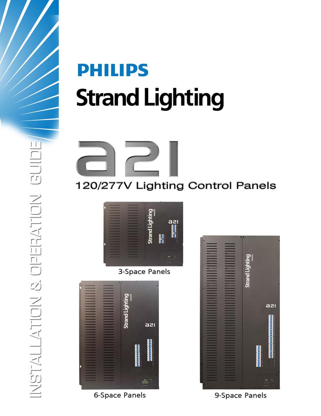
5 A21 Lighting Control Panel Installation & Operation Guide PREFACE 1. About This Guide The document provides installation and operation instructions for the following A21 products: A21 Lighting Control Panel, 3-Space A21 Lighting Control Panel, 6-Space A21 Lighting Control Panel, 9-Space Notes: A21 dimmer cabinets may be populated with either 120V or 277V modules, but not both. A21 dimmer cabinets may be ordered factory configured for UL924 circuits. 120V and 277V dimmer modules are not interchangeable, and must be installed in the appropriate voltage A21 Lighting Control Panel. Please read all instructions before installing or using this product. Retain this guide for future reference. 2. Additional Manuals Individual installation documents are available for each A21 Relay and Dimming Module. About This Guide 3
6 Installation & Operation Guide A21 Lighting Control Panel OVERVIEW 1. About A21 Lighting Control Panels Strand Lighting A21 Lighting Control Panels are high-performance, wall mounted lighting control panels which offer a wide range of dimming and relay modules to accommodate any lighting control application. All A21 Lighting Control Panels accept any combination or mixture of LED, incandescent, and fluorescent dimming or non-dim modules to fit any project needs. A21 Lighting Control Panel IGBT Dimming Modules contain an on-board, intelligent microprocessor that adjusts and maintains proper voltage and current in response to changes detected in the load and electrical service, which serves to extend lamp life. The microprocessor also automatically suppresses surges, and protects against short circuits. IGBT dimmers significantly reduce neutral harmonics and when configured to operate in Low Harm mode. 2. Installation Overview The following steps are required to successfully install an A21 Lighting Control Panel: 1) Review this document completely before starting the installation. 2) Unpack and inspect equipment. Compare the equipment you received with your packing list. If these do not match, contact Strand Lighting Customer Service at: STRAND (U.S.) or ) Gather tools. Refer to "Tools List" on page 5. 4) Chose an appropriate location for installation. The Lighting Control Panel(s) should be installed in an area of "office" level cleanliness. The room in which it is installed should have sufficient volume to allow exhaust air to circulate and cool. For more details and clearance requirements, refer to "Location and Clearances" on page 5. 5) Plan the wire routings and connection order. Decide where the Feed, Load, and Control wiring will enter the Lighting Control Panel(s). 6) Remove access panels and knockouts in the Lighting Control Panel(s) as required for conduit or busway entry. Perform all conduit connections to the panel before it is permanently installed. Be sure to remove all knockout debris. 7) Securely mount the Lighting Control Panel and terminate all Feed, Load, and Control wiring following the directions in this manual. Clean up the work site and Lighting Control Panel(s) for checkout by Strand Lighting Technical Services (see "Notice To Contractor" on page 34). 8) Contact Strand Lighting when Lighting Control Panel(s) is installed and ready for checkout. 4 Overview
7 A21 Lighting Control Panel Installation & Operation Guide 3. Tools List The following is a basic list of tools recommended for this installation: Drill (for mounting holes) Hammer (for removing knockouts) Phillips screwdriver Small flat screwdriver Adjustable wrench Ratchet and assorted sockets Wire cutter Wire stripper Heat shrink tubing Pencil Knife Conduit and fittings Digital voltmeter / True RMS 4. Location and Clearances When installing A21 Lighting Control Panels, the location site MUST meet the following requirements: Wall must be capable of supporting the weight of the lighting control panel. Minimum clear ventilation spacing for side-by-side mounting: 6 inches Minimum clear ventilation spacing for mounting next to an adjacent wall: 6 inches Only the 3-Space Lighting Control Panels may be stacked. Minimum clear ventilation spacing between panels for vertical stacking: 12 inches All cabinets require 12 inches of clear ventilation space above and below. Do not recess (flush mount) the panel. Panel must be surface mounted to provide proper ventilation. Indoor Use Only: The unit MUST be installed indoors. Dry Locations Only: The unit can only be installed in an "office clean" area that is never exposed to moisture of any kind. Strand Lighting is not responsible for damage to equipment caused by moisture, paint, dust, solvents or cleaning supplies. Installation location should have sufficient volume to allow exhaust air to circulate and cool. Refer to National Electrical Code and local codes to determine whether additional requirements must be met. CAUTION: 6- and 9-Module Panels should never be stacked due to thermal requirements. Tools List 5
8 Installation & Operation Guide A21 Lighting Control Panel 5. Components Note: 3-Module and 6-Module Panels are shown in Figure 1, however, these components are typical for all models. FRONT VIEW 3-Module Panel D VIEW 6-Module Panel 1 Ground Bus Bar 2 Neutral Bus Bar 3 Main Feed Terminal Block 4 Mounting Bracket 5 Dimmer Module - see detail below 6 Backplane PCB 7 Circuit Breakers 8 Power Supply Fuse 9 Rack Control Module (RCM) - see detail below (not required for Slave panels) 10 Power Supply 11 Knockouts (for low voltage control wiring) 12 Removable Panels (for feed and load wiring) 13 Main Circuit Breaker (optional on 6-Module and 9-Module panels only) 14 Control Cable Wireway (low-voltage) 11 Dimmer Module (typical) Rack Control Module (RCM) D VIEW BACK VIEW 1 Module Connector 2 Mounting Screw Hole (4) 3 Focus Button 4 LED Indicators Cover Plate 2 Modular Cable 3 RCM Processor Card 4 Connector Card Figure 1: A21 Panel Overview 6 Overview
9 A21 Lighting Control Panel Installation & Operation Guide INSTALLATION 1. Mounting Panel to Wall A21 Lighting Control Panels are intended for wall mounting for un-obstructed, natural convection cooling. To mount the panel: Step 1. Determine position and spacing for each type of A21 Lighting Control Panel. Refer to "Location and Clearances" on page 5 and "Appendix B: Specifications" on page 29. Step 2. Ensure that wall is capable of supporting the weight of the lighting control panel. Step 3. Remove front cover. Step 4. Mark hole placement on wall. Step 5. Using four 1/4" bolts - or six 1/4" bolts for 9-Module Panels - (not included), secure panel in place. Step 6. Repeat for all other panels. Note: The A21 3-Module Panel is used to illustrate the installation in Figure 2. However, the horizontal spacing dimensions apply to all A21 Lighting Control Panels including the 6- and 9-Module versions. For overall dimensions for each model, refer to "Appendix B: Specifications" on page 29. Center-To-Center Mounting in / mm Mounting Hole (4) - Use 1/4" Bolt FRONT VIEW, COVER REMOVED (3-Space Panel) Figure 2: Mounting the Panel Mounting Panel to Wall 7
10 Installation & Operation Guide A21 Lighting Control Panel 2. Feed (Line Power) Wiring WARNING: You must have access to a main circuit breaker or other power disconnect device before installing any wiring. Be sure that power is disconnected by removing fuses or turning the main circuit breaker off before installation. Installing the device with power on may expose you to dangerous voltage and damage the device. A qualified electrician must perform this installation. WARNING: Refer to National Electrical Code and local codes for cable specifications. Failure to use proper cable can result in damage to equipment or danger to persons. CAUTION: Wire openings MUST have fittings or lining to protect wires/cables from damage. Use 90 C copper wire only! Aluminum wire may not be used. CAUTION: Use a separate wire for each neutral. DO NOT use common neutrals. CAUTION: Failure to use the proper torque when tightening the set screws will cause premature failure of the equipment! To connect feed wiring: Step 1. Disconnect main power to A21 Panel. Step 2. Route FEED wires from power source to top or side of panel. (Feed wires cannot be fed through bottom of the unit.) Step 3. Remove wire access panel(s) as required. See Figure 3. Step 4. Install conduit fittings or insert lining materials in the access panel opening. Step 5. Replace wire access panel if using conduit. Step 6. Pull feed cables through prepared openings. Step 7. Strip 1-3/8 inches of insulation from end of each cable. Step 8. Strip 7/16 inch of insulation and connect Phase, Neutral, and Ground wires to appropriate terminals. (Line connections are labeled A, B and C.) Step 9. Tighten main lug set screws to proper torque termination as shown in the table below: Removable panels may be punched for FEED and LOAD wiring Knockouts provided for low voltage CONTROL wiring Figure 3: Wiring Inputs TERMINAL Neutral Bus Ground Bus Power Distribution Block (3-Space Racks Only) Power Distribution Block (6- & 9-Space Racks Only) TIGHTENING TORQUE 350kcmil - #6 AWG 275 in-lbs #4-14 AWG 45 in-lbs 350kcmil - #6 AWG 275 in-lbs #4-14 AWG 45 in-lbs 2/0 AWG - #14 AWG 120 in-lbs #2-14 AWG 20 in-lbs 350kcmil - #6 AWG 275 in-lbs #10-14 AWG 15 in-lbs Step 10. Remove all knockout pieces and debris. Note: Refer to Figure 4 on the following page for complete feed wiring diagram. 8 Installation
11 A21 Lighting Control Panel Installation & Operation Guide! Feed wiring on terminals for A21 Blank Panel (74181) can be wired by factory for Dual or Quad Module as specified by customer. NEUTRAL GROUND Mod (277V) }-- 120/208V 3-Phase 4-Wire & Ground Feed (120V Panels & Modules), or 277/480 3-Phase 4-Wire & Ground Feed (277V Panels & Modules) Mod (277V) (277V) } Tan wire connections required only for PowerDim HDF / PowerSpec HDF fluorescent dimming Mod (277V) (277V) } Quad slot equipped with four circuit breakers to accommodate four circuit relay or dimmer module. 120V Panel Color Code: 277V Panel Color Code: Mod (277V) (277V) A Phase - Black B Phase - Red C Phase - Blue Neutral - White Ground - Green A Phase - Brown B Phase - Orange C Phase - Yellow Neutral - Gray Ground - Green (blank) Mod 5 } Dual slot equipped with two circuit breakers to accommodate two circuit relay or dimmer module (blank) Mod 6 } Dual slot equipped with four circuit breakers to accomodate three-wire fluorescent dimmer module. Figure 4: Feed Wiring Diagram Feed (Line Power) Wiring 9
12 Installation & Operation Guide A21 Lighting Control Panel 3. Installing Dimmer Modules Any combination of A21 dimming and relay modules may be installed in the Lighting Control Panel. A21 Panels may be populated with either 120V or 277V Dimmer Modules, but not both. Blank covers (74181) MUST be installed in any unused spaces. Note: If Dimmer Modules were not included with the initial installation package, proceed directly to Load Wiring section. Dimmer Modules may be installed at a later time. The A21 Lighting Control Panel has been shipped from the factory with shorting plugs installed on all circuits. These shorting plugs are located in the load connection terminal blocks (the shorting plug is the red tab protruding from the green terminal block). The shorting plugs allow circuits to be energized by operating the associated circuit breaker, even if a dimmer module has not been installed. For proper operation of the A21 Dimmer Modules, shorting plugs must be removed prior to use. To remove a shorting plug: Step 1. Disconnect main power to A21 Panel. Step 2. Open the dimmer module side of the panel s front cover. Step 3. Identify the circuits that will require removal of the shorting plug. Step 4. Firmly grasp the exposed red tab of the shorting plug (Figure 5). Step 5. Gently pull on the tab of the shorting plug. Step 6. It is recommended that all shorting plugs be saved for future use. (In the event service is needed on any module, the jumper can be re-installed to provide constant power to the load circuit.) Step 7. Close panel cover. Step 8. Energize panel. Note: Shorting plugs may be left in all empty dimmer slots and may be used as constant current circuits within the approved current rating of the circuit breaker. Screw (4) Screw (4) Focus Button & Status LEDs Blank Cover (74181) Dimmer Module Note: The A21 9-Module Panel is used to illustrate the installation in this figure. However, module installation is identical for all A21 Panel models. Load Terminal Block Shorting Plug DETAIL Terminal Figure 5: Installing Modules and Blank Covers To install modules: Step 1. Unpack module and properly recycle or discard packaging materials. (Be sure to keep the instruction sheet for future use.) Step 2. Disconnect main power to A21 Panel. Step 3. Open the dimmer module side of the panel s front cover. Step 4. Determine proper mounting location for the Dimmer Module. When possible, lower modules should be installed first. Step 5. If present, remove blank cover (74181) from location where module is to be installed. See Figure 5. Step 6. Gently insert module into lighting control panel, heatsink first. Secure module using four screws (provided). Step 7. For PowerDim/HDF modules only: Connect tan control wire to screw terminal on module. (Circuit #1 on module will be top screw.) Tighten screw to a torque of 5 in-lbs. Step 8. For Mark 7 dimmer modules only: Connect violet/grey control wire to screw terminal on module. (Circuit #1 on module will be top screw.) Tighten screw to a torque of 5 in-lbs. Step 9. Close panel cover. 10 Installation
13 A21 Lighting Control Panel Installation & Operation Guide 4. Load Wiring WARNING: You must have access to a main circuit breaker or other power disconnect device before installing any wiring. Be sure that power is disconnected by removing fuses or turning the main circuit breaker off before installation. Installing the device with power on may expose you to dangerous voltage and damage the device. A qualified electrician must perform this installation. WARNING: Refer to National Electrical Code and local codes for cable specifications. Failure to use proper cable can result in damage to equipment or danger to persons. CAUTION: Wire openings MUST have fittings or lining to protect wires/cables from damage. Use 90 C copper wire only! Aluminum wire may not be used. CAUTION: Use a separate wire for each neutral. DO NOT use common neutrals. CAUTION: Failure to use the proper torque when tightening the set screws will cause premature failure of the equipment! The A21 Panel will need to be wired for the Load circuits. Use #10 AWG Solid Core or #12 AWG Stranded Core Max. To connect load wiring: Step 1. Disconnect main power to A21 Panel. Step 2. Route all LOAD wiring to side of panel. (Load wires cannot be fed through bottom of the unit.) Step 3. As required, remove wiring covers or knockout holes to accommodate wiring (see Figure 3 on page 8). Step 4. Route LOAD GROUND wires, if any, to Ground Bus. Strip 7/16 inch of insulation and terminate using torque values as shown in the table below. Step 5. Separate LOAD NEUTRAL wires and route to Neutral Bus (see Figure 1 on page 6). Strip 7/16 inch of insulation and terminate using torque values as shown in the table. Step 6. Route LOAD HOT wires to their individual terminals located on the Backplane PCB (see Figure 6 below). Strip 7/16 inch of insulation and terminate in spring-cage terminals using small flat screwdriver (no torque setting required). CAUTION: Do not attempt to "push" load wires into spring-cage terminals without first inserting the screwdriver into the appropriate slot (Figure 6). Failure to install load wires as directed may damage the spring-cage connector, and may void manufacturers warranty! TERMINAL Neutral Bus Ground Bus Backplane PCB TIGHTENING TORQUE # in-lbs # in-lbs Spring-Cage Connection (no torque required) Wire (Solid or Stranded) Screwdriver Figure 6: Backplane Load Wiring Terminals Load Wiring 11
14 Installation & Operation Guide A21 Lighting Control Panel Terminal Block (on module cover) (277V) (277V) POWERDIM/HDF TAN WIRE A (CONTRACTOR WIRING) POWERDIM/HDF TAN WIRE B (CONTRACTOR WIRING) BREAKER A LOAD A (CONTRACTOR WIRING) BREAKER B LOAD B (CONTRACTOR WIRING) (277V) BREAKER A LOAD A (CONTRACTOR WIRING) BREAKER B LOAD B (CONTRACTOR WIRING) BREAKER C LOAD C (CONTRACTOR WIRING) BREAKER D LOAD D (CONTRACTOR WIRING) (277V) (277V) (277V) BREAKER A LOAD A (CONTRACTOR WIRING) BREAKER B LOAD B (CONTRACTOR WIRING) (277V) (277V) BREAKER A LOAD A (CONTRACTOR WIRING) BREAKER B LOAD B (CONTRACTOR WIRING) BREAKER C LOAD C (CONTRACTOR WIRING) BREAKER D LOAD D (CONTRACTOR WIRING) Terminal Block (on module cover) for Violet/Grey Control Wiring (typical for 2- and 4-circuit modules) (277V) (277V) DIMMER A+ (CONTRACTOR WIRING) DIMMER A- (CONTRACTOR WIRING) BREAKER A LOAD A (CONTRACTOR WIRING) BREAKER B LOAD B (CONTRACTOR WIRING) Figure 7: Module Load Wiring Diagram 12 Installation
15 A21 Lighting Control Panel Installation & Operation Guide 5. Control Wiring A21 Lighting Control Panels may be controlled by the following methods: DMX512 Vision.net Optional ShowNet Ethernet (10/100BaseT) Auxiliary inputs: Panic Control and Fire Alarm Signal Local control through Rack Control Module (RCM) For approved wire types per control method, refer to "Appendix A: Standard Wiring" on page 25. Each Lighting Control Panel contains a Control PCB for connection of control wiring. The Control PCB also contains jumpers for termination of DMX512 signal and connection to Slave panels. To connect control wiring: Step 1. Route control wiring from source to side of Lighting Control Panel. Step 2. Remove knockout(s) as required. See Figure 1 on page 6. Step 3. Install conduit fittings or insert lining materials in the knockout opening. Step 4. Pull control wiring through prepared openings. CAUTION: Wire openings must have fittings or linings to protect wire and cable insulation. Step 5. Prepare cabling as shown in "Appendix A: Standard Wiring" on page 25. Step 6. Connect wiring to appropriate location on Control PCB. See Figure 8 on the following page. Step 7. Set DMX A Thru termination jumper as required. Control Wiring 13
16 Installation & Operation Guide A21 Lighting Control Panel Default setting is OFF (consult factory before setting otherwise) Closed = Fire Alarm (function active) Activates Preset 8 For optional grounded DMX512 receiver topology Fire Alarm Signal input (requires a dry contact) Terminate if nothing is connected to DMX A Thru Vision.net input Ethernet Input* (*only active if network node installed) Panic Control input (requires a dry contact) DMX Thru DMX Input LED - indicates LV power Factory Use Only To Slave panel Closed = Panic (function active) Activates Preset 7 Figure 8: Control PCB Note: Refer to "Appendix A: Standard Wiring" on page 25 for complete control wiring pin-out and termination requirements. 14 Installation
17 A21 Lighting Control Panel Installation & Operation Guide 6. Installing Rack Control Module (not required for slave cabinets) A21 Lighting Control Panels are controlled by the A21 Rack Control Module (RCM). To install RCM: Step 1. At required panel, remove control module cover plate by removing four screws (Figure 9). Step 2. Install RCM. Step 3. Connect modular cable from RCM board to display board on cover plate. Step 4. Re-install head-end cover plate and secure with four screws. Note: Slave Cabinets do not require an RCM to be installed. Screw (4) Rack Control Module (RCM) Modular Cable Cover Plate Figure 9: Installing Rack Control Module 7. Addressing/Configuring the Backplanes Note: Backplane PCBs are pre-configured for your application at the factory. This information is included as reference only in the event a Backplane PCB requires re-configuration or changing in the future. A21 Dimmer Modules are connected to a Backplane PCB(s), which is pre-installed in the panel. Each Backplane PCB accommodates up to three module connections. Depending on your dimming system, there may be up to 16, three-module Backplane PCBs connected together, and cannot contain more than 96 dimmers (Dual Dimmer Module = 2 dimmers; Quad Dimmer Module = 4 dimmers) total when panels are used in a Master/Slave configuration. Before any dimmer modules are installed, it will be necessary to address the Backplane PCB(s). Each Backplane has a rotary switch that is used to set the Backplane's address (0-15). Each Backplane has a set of jumpers that allow it to be configured as a Dual or a Quad Backplane. Set to Dual only if all dimmer modules to be connected to the backplane are Dual dimmers. Each Backplane also has a termination header. The termination is set to Term only on the first and last Backplane (all others are set to Thru). The first Backplane is the top Backplane in the cabinet that contains the A21 Rack Control Module (RCM). The Backplanes will be addressed from top to bottom in the first cabinet. If another slave cabinet (no RCM) is to be added, continue the addressing from top to bottom as well. Continue this method of addressing until the last Backplane in the last cabinet is connected. Slave cabinets are connected to the first cabinet and to additional slave cabinets using an 8-conductor (CAT5e UTP) cable, no longer than 1000 feet system wide. Installing Rack Control Module (not required for slave cabinets) 15
18 Installation & Operation Guide A21 Lighting Control Panel To address/configure Backplanes: First Backplane: Step 1. Set rotary switch of first Backplane to 0. (Refer to Figure 10.) Step 2. Set Backplane configuration jumper to either Dual or Quad. Step 3. Set Termination jumpers to Term. Next Backplane: Step 1. a) If previous Backplane is set to Dual, then set rotary switch on this Backplane to the previous Backplane's setting plus 1. Example: If previous setting was 0, then set this switch to 1. b) If previous Backplane is set to Quad, then set rotary switch on this Backplane to previous Backplane's setting plus 2. Example: If previous setting was 0, then set this switch to 2. Step 2. Set Backplane configuration jumper to either Dual or Quad. Step 3. If this is not the last Backplane to be configured, then set Termination jumpers to Thru. If this is the last Backplane to be configured, then set the Termination jumpers to Term. Step 4. Repeat the above 3 steps for all Backplanes. Quad/Dual Jumper Rotary Switch (Cabinet #) Thru/Term Jumper Figure 10: Backplane PCB 16 Installation
19 A21 Lighting Control Panel Installation & Operation Guide CONFIGURATION USING RCM LCD MENU 1. Overview The A21 Lighting Control System can be configured directly at the Rack Control Module (RCM) using the built-in LCD Menu. Please note that while the built in LCD menu will display all system status information, it provides only basic configuration capabilities. Strand Lighting's Dimmer.net software provides an advanced interface for configuring A21 Lighting Control System options. Where applicable, refer to the Dimmer.net manual for full explanations of each configuration option. Dimmer.net software and manuals may be downloaded at 2. Menu Operation The RCM LCD Menu provides local control for accessing all system status information and for making a limited amount of configuration changes to that particular RCM. (If there are multiple RCMs in the system, changes would need to be made at each RCM.) Upon power up, the LCD Menu will display the Philips logo followed by the current RCM software version and RCM name. After briefly displaying this information, the MAIN MENU will appear. Note: To return to the power up screen after boot up, press the [Escape] button. Escape Button - Backs up one menu level. Right/Left/Up/Down Buttons (4) - Navigates menu system. Menu ESCAPE Arrow Indicator - Indicates menu can be scrolled to view more choices. MAIN MENU: System Status Dimmer Status Select Local Preset Menu Configuration System Configuration POWER FAULT VISION.NET DMX Status LEDs (refer to Troubleshooting section) Figure 11: LCD Menu Enter Button - Accesses details, activates a field, or enters a setting, depending on current menu. 3. LCD Menu System The Head-End Processor LCD Display Menu system consists of eight main categories. To navigate the menus, press the four navigation buttons as required (Figure 11). When the desired menu is reached, press [Enter] to display the menu options. Use navigation and [Enter] buttons to view status and configure the LCD Menu as required. Overview 17
20 Installation & Operation Guide A21 Lighting Control Panel LCD Menu Structure MAIN MENU - System Status (SYSTEM STATUS) - Dimmer Status (DIMMER STATUS) - Select Local Preset (SELECT PRESET) - Menu Configuration (MENU CONFIG) - System Configuration (SYSTEM CONFIG) - Dimmer Options Config (DIMMER OPTIONS) - Dimmer Input Config (DIMMER INPUT) - Dimmer Presets Config (EDIT PRESETS) MAIN MENU: System Status Dimmer Status Select Local Preset Menu Configuration System Configuration SYSTEM STATUS (status information shown, no user-selectable options) Sub Menu Options Comments Type Displays product type Dimmer Status Dimmer Present Dimmers with Errors Firmware Displays either OK (no errors) or Errors Displays the number of dimmers in the dimmer cabinet Displays the number of dimmers with errors Displays Processor s current firmware version as: 86-XXXX vx.xx DIMMER STATUS (status information shown, no user-selectable options) Sub Menu Options Comments Slot Level TMP Displays dimmer information being viewed (and its DMX512 address) Displays dimmer s current operational level (in percentage) Displays current temperature of dimmer (displayed in both C and F) Line Displays input line voltage (in VAC) Load Status Errors Displays connected load to dimmer (displayed in watts) Status of dimmer Normal, Non-Dim, or Breaker Off? (if no power to dimmer) Displays if the dimmer is experiencing any errors Mod Displays module type Version Displays dimmer s firmware version If [Enter] button is pressed, the following fields change in Dimmer Status as follows: Level [0] to [255] Status [00] Config: [XX] Errors [00] Panel: [XX] Continued next page 18 Configuration Using RCM LCD Menu
21 A21 Lighting Control Panel Installation & Operation Guide LCD Menu Structure (continued) Continued from previous page SELECT PRESET Sub Menu Options Comments Select a Preset None / 1 / 2 / 3 / 4 / 5 / 6 / 7 / 8 Manually selects a preset via the unit s processor (as in testing processor communication and dimmer operation) MENU CONFIG Sub Menu Options Comments Backlight On (min) (in minutes) LED ON (MIN) Display Contrast (%) Always (always on) / 1 to 60 minutes (in 1 minute increments) Always (always on) / 1 to 60 minutes (in 1 minute increments) 0 to 100% (in 1% increments) Sets the amount of time the unit s processor LCD display backlight is on after the last button press Set the amount of time the status LEDs flash during operation. The Power LED normally flashes (as a heartbeat) when set to Always. When the option is set to a specific time, the LED will only flash in the time increment (e.g., every five minutes). Sets the contrast level of the LCD Display SYSTEM CONFIG Sub Menu Options Comments DMX A Enabled / Disabled Enables or disables the DMX A port DMX B (Pathport) Enabled / Disabled Enables or disables the DMX B port Vision.net Network Enabled / Disabled Enables or disables the Vision.net Network port Vision.net Station ID Off / 1 thru 255 Sets Vision.net Station ID for the unit DMX Hold (hh:mm) (in hours:mins) None / 0:01 / 0:05 / 0:10 / 0:15 / 1:00 / 2:00 / 4:00 / 12:00 Power-up Preset None / 1 / 2 / 3 / 4 / 5 / 6 / 7 / 8 Power-up Hold Preset Clear Config Port Forever / 0:01 / 0:05 / 0:10 / 0:15 / 1:00 / 2:00 / 4:00 / 12:00 / 24:00 None / DMX Ethernet / RS232 Sets the amount of time the dimmer cabinet will keep and adhere to the last DMX512 levels Sets what preset the dimmers go to when dimmer cabinet is initially powered Sets the amount of time the dimmers will go and stay at the preset level (if set) when the dimmer cabinet is initially powered. Will follow DMX512 commands at anytime. Sets how Presets are cleared either never or via DMX512 Sets configuration port to Ethernet or RS232 input Panic Inputs Normally Open / Normally Closed Sets panic inputs to open or closed Continued next page LCD Menu System 19
22 Installation & Operation Guide A21 Lighting Control Panel LCD Menu Structure (continued) Continued from previous page DIMMER OPTIONS Sub Menu Options Comments Slot Mode Non-Dim% 0 to 100% RPC (Reverse Phase Control) / FPC (Forward Phase Control) / Non-Dim / LED - RPC, LED-FPC Voltage at Full (VAC) 100 / 110 / 115 / 120 Transition (µs) (in microseconds) 400 / AUTO* Displays dimmer (1 through X) for the dimmer to be configured, and its DMX512 address (DMX XXX) Sets dimmer operation. Also allows user to set the dimmer to Non-Dim operation (as a On or Off device). LED mode is for line voltage LED fixtures that require locked reverse phase control dimming (set at 400µS). When dimmer is in non-dim mode, this option sets the dimmer's threshold level (selection 0 to 100%). Levels below this will turn the dimmer off and levels equal to or above this percentage will turn them on. Sets dimmer operational voltage. Using a lower voltage than lamp specification can prolong lamp life. Options available (in both FPC and RPC) are either 400µS (set) or AUTO (automatically and continuously adjusts between 400µS to 800µS) *Note, when "LED" option is selected in "Mode", the dimmer is set to 400 µs and cannot be changed to AUTO. Response (ms) (in milliseconds) Sets response time in milliseconds Dimmer Curve High Trim 1 to 100% Low Trim 0 to 99% Always On Preheat Linear / Square Law / Invert / Slow Bottom / Fast Bottom / Fast Top / Full at 1 / Out at 100 / Preheat 5% / Preheat 10% / Hot Patch / Adv Mark 10 (Advance Mark 10 fluorescent ballasts) Yes or No Yes or No Sets dimmer curve (dimming operation) for each dimmer in the dimmer cabinet Sets the top end of the dimmer operational limit Sets the low end of the dimmer operational limit If set to "Yes", then the dimmer stays on to the Low Trim setting. Allows dimmer to be set to preheat mode. Normally preheat mode is used to "speed up" large wattage lamps so they behave more like smaller ones Continued next page 20 Configuration Using RCM LCD Menu
23 A21 Lighting Control Panel Installation & Operation Guide LCD Menu Structure (continued) Continued from previous page DIMMER INPUT Sub Menu Options Comments Dimmer Dimmer number DMX A Dimmer number specified for DMX A DMX B (Ethernet) Dimmer number specified for DMX B Room Room number Channel Channel number DMX A Priority None / Primary / Fallback Sets priority level for DMX A DMX B Priority None / Primary / Fallback Sets priority level for DMX B Present Priority None / Primary / Fallback Sets priority level for Present EDIT PRESETS Sub Menu Options Comments Dimmer Set dimmer number Slot Displays dimmer (1 through X) for the dimmer to be configured (and its DMX512 address) Preset 1 / 2 / 3 / 4 / 5 / 6 / 7 / 8 Selects the preset to be programmed Level (%) Dimmer Set 0 to 100% (in 1% increments) One / All / Capture (Yes / No)* * Next selection is "Capture ALL Dimmers? (Yes / No) Selects the preset level of the dimmers (each dimmer is individually programmable) Allows users to set preset to one or all dimmers (at the same time) or Capture (snapshot) a look from all dimmers LCD Menu System 21
24 Installation & Operation Guide A21 Lighting Control Panel TROUBLESHOOTING 1. Status Indicators LED status indicators located at the Head-End Processor provide feedback for power input, control input, and error conditions. ESCAPE MAIN MENU: System Status Dimmer Status Select Local Preset Menu Configuration System Configuration Status LEDs POWER FAULT DMX A DMX B Figure 12: Head-End Processor The status indications are as follows: LED Condition Meaning POWER Flashing Green Indicates power is active to the Rack Control Module (RCM). FAULT Flashing or Steady Red Indicates an error condition in the cabinet. If illuminated, remove power to the panel, wait 15 seconds, and re-energize panel. If error condition persists, please contact Strand Lighting Technical Support. DMX A Illuminating Yellow Indicates presence of DMX512 control signal on DMX Input A. DMX B Illuminating Yellow Indicates presence of DMX512 control signal on DMX Input B (if Network Node installed). 22 Troubleshooting
25 A21 Lighting Control Panel Installation & Operation Guide 2. Troubleshooting Procedures To physically examine the system: Step 1. Check LEDs at front of RCM. (Refer to Figure 11 on page 17.) Step 2. At main circuit breaker(s), check for tripped circuits. Step 3. Disconnect power to the system. Step 4. Check for damaged or loose control and/or load connections. To further troubleshoot: Refer to the Troubleshooting Flow Chart below. Circuit / Channel doesn t work Push Focus button Voltage into the dimmer not present. Check supply. Yes Did button light up? No Is Focus button LED solid green? Yes Check console for DMX output. Check the data cable. No Is Focus button LED solid red? Yes Dimmer is either not communicating with RCM or has detected an error. Check Dimmer Status for errors. No Is Focus button LED flashing green? Yes Check lamp. Dimmer is detecting no load. No Is Focus button LED flashing red? Yes Lower circuit wattage. Dimmer is detecting an overload. Figure 13: Troubleshooting Flow Chart Troubleshooting Procedures 23
26 Installation & Operation Guide A21 Lighting Control Panel EMERGENCY LIGHTING OPERATION (UL924) 1. Overview When required, the A21 Lighting Control Panel may be used to energize emergency lighting circuits in the event of a loss of power. A21 Panels may be custom configured at the factory with special software and hardware to allow the unit to comply with UL924 Electronic Bypass. When configured in this mode, the A21 Panel allows select circuits to be energized at 100% output upon activation by a control signal. Circuits not identified as emergency may be locked "Off" or can "Ignore" the emergency state and still respond to local controls. When A21 Panels are used as part of an emergency lighting control system, feed power supplied to the A21 Panel must be switched by an upstream UL1008 Listed Transfer Device. To trigger the A21 Panel to enter the emergency mode, a control signal (Contact-Closure, open) must be provided to the panel, and connected to the Panic #1 input, located on the Control PCB. Strand Lighting recommends the use of a 3-phase UL924 or UL 1008 compliant phase loss relay interface to monitor normal power and provide a control signal to the A21 Panel in the event of a disruption of any phase of the normal power feed. When the A21 Panel is in an active emergency mode, the LCD display will read EMERGENCY MODE ACTIVE and the display backlight will flash. IMPORTANT! UL924 operation applies only to A21 Panels which have been configured at the factory for Emergency Lighting Operation. If a previously installed A21 Panel is required to operate emergency lighting and needs to be updated in the field, please contact Strand Lighting Technical Support at Emergency Lighting Operation (UL924)
27 A21 Lighting Control Panel Installation & Operation Guide APPENDIX A: STANDARD WIRING 1. DMX512 DMX512 Terminal XLR Pin Name WE Color Code (e.g., Belden #8132) IECA Color Code Belden Standard Color Code GND 1 Drain Wire (Shield) Drain (Shield) Drain (Shield) CAT5e Color Code Brown (8) White/Brown (7) DMX - 2 White w/ Blue Black Black (of Red pair) Orange (2) DMX + 3 Blue w/ White White Red White/Orange (1) AUX - 4 White w/ Orange Red Black (of White pair) Green (6) AUX + 5 Orange w/ White Green White Green/White (3) Contractor is Responsible for All Terminations 1) Only approved EIA-485 cable types may be used. Approved types are: Belden #9829 and TMB Proplex #PC224T An acceptable plenum rated cable is: Belden # ) Category 5e cable may be used for DMX512. Approved types are: Belden #1583A and Belden #1585A (Plenum). 3) Cable MUST be terminated exactly as shown here. 4) DMX512 cable runs MUST be routed in a "Daisy- Chain" configuration as shown in your drawing set, if provided. DO NOT convert these cables to home runs. 5) DMX512 cable runs should all be in metal conduit. Runs in exposed areas must be in metal conduit. Maximum cable run should not exceed 1000 feet. BELDEN #9829 (NOT BY STRAND) Additional Resources for DMX512 For more information on installing DMX512 control systems, the following publication is available for purchase from the United States Institute for Theatre Technology (USITT), "Recommended Practice for DMX512: A Guide for Users and Installers, 2nd edition" (ISBN: ). USITT Contact Information: USITT 315 South Crouse Avenue, Suite 200 Syracuse, NY USA or DMX512 25
28 Installation & Operation Guide A21 Lighting Control Panel 2. Vision.net Networks (SVN/485) Pin Number Signal Name CAT5e Wire Color 1 Data + White w/ Orange 2 Data - Orange 3 SHIELD Shield VDC White w/ Green 5 Signal GND Green VDC White w/ Blue 7 Signal GND Blue VDC White w/ Brown 9 Signal GND Brown Contractor is Responsible for All Terminations 1) Only approved cable types may be used. Approved types are: Belden #1583A and Belden #1585A 2) Cable MUST be terminated exactly as shown here. Total length of cable in Vision.net Network Wiring must NOT exceed 1000 feet. 3) Cable runs should be routed in a "Daisy-Chain" configuration as shown in your drawing set, if provided. DO NOT convert these cables to home runs. 4) Maximum station quantity subject to power supply and system requirements. Please consult factory for specific information. 3. Termination of Shielded Cable Dimension Name Minimum Maximum for Terminal Maximum for LXR (In-Line) A Remove Cable Jacket 1" (25.4mm) 2-1/4" (60mm) 1-1/4" (31.8mm) B Drain Wire Heatshrink Dim 'A' - 1/8" (3.2mm) - - To terminate shielded cable: Step 1. Strip off specified length of outer jacket. Step 2. Cut shield (foil or braid) flush to outer jacket. DO NOT cut drain wire. Step 3. Fit specified length of 1/16" heat shrink tubing over the drain wire. Step 4. For solder connections, fit a 1/2" length of 1/16" heat shrink tubing over each conductor. Step 5. Fit a 1" length of 3/8" heat shrink tubing over the entire cable. Position it so that 3/4" of its length is over the cable jacketing, and 1/4" of its length is over the loose conductors. Step 6. Strip 1/8" inch of the insulation from each of the conductors. Step 7. Terminate the conductors on the terminal block, or solder the terminals as specified. Step 8. For solder connections, shrink the individual 1/2" lengths of heat shrink tubing over the solder terminals. Step 9. Shrink the remaining heat shrink tubing. Step 10. Apply the appropriate ID label to the cable at the end of the outer heat shrink tubing. 26 Appendix A: Standard Wiring
29 A21 Lighting Control Panel Installation & Operation Guide 4. Termination of Ethernet Cable Function Pair # Pin Out (T568B) Wire Color (T1) (R1) Tx + (T2) Tx - (R2) Rx + (T3) Rx - (R3) (T4) (R4) White w/ Blue Blue White w/ Orange Orange White w/ Green Green White w/ Brown Brown Cable Type (10/100 Base-T Ethernet) Belden #1583A Nominal O.D (5.54 mm) Belden #1585A Nominal O.D (5.23 mm) Description CATEGORY 5e: Non-plenum rated 4-Unshielded Twisted Pairs (UTP) #24 AWG CATEGORY 5e: Plenum rated 4-Unshielded Twisted Pairs (UTP) #24 AWG To terminate Ethernet cable: Step 1. Strip off outer jacket - approximately 1-1/2" (37.6mm) Step 2. Fit a piece of 1-1/8" (28.6mm) long heat shrink tubing over the cable extending out 1/4" (8.25mm) from outer jacket. Step 3. Terminate approximately 1/2" (12.2mm) from end of conductors on Type 110 punch down block or connector per schedule (T568B) Maximum untwist of conductors to terminations is 1/2" (12.2mm) Trim excess leads. Step 4. Shrink tubing and add appropriate ID label to the cable at the end of the heatshrink tubing. System topology and labeling should follow TIA/EIA-568B and TIA/EIA-606 as applicable. Per TIA/EIA-568B, Maximum length of any horizontal cable run (i.e. between Ethernet RJ-45 receptacle (work area) and Patch Panel) is 90 meters; Maximum length of any CATEGORY 5e cables at the Ethernet RJ-45 receptacle (work area) is 3 meters. Ethernet equipment (e.g. Patch Panels, Hubs or Switches) should be maintained in an environment of C (64-75 F) and 30% - 55% relative humidity per TIA/EIA-569-A. Maximum length of any segment (cable run - including device cables - between Hub or Switch and Node) is 90 meters. Maximum network diameter (distance between any two Nodes) is 180 meters. Termination of Ethernet Cable 27
30 Installation & Operation Guide A21 Lighting Control Panel 5. Master/Slave Wiring (DIM96) Pin Number Signal Name CAT5e Wire Color VDC White w/ Orange VDC Orange 3 + RX White w/ Green 4 - RX Green 5 + TX White w/ Blue 6 - TX Blue 7 GND White w/ Brown 8 GND Brown Contractor is Responsible for All Terminations 1) Only approved cable types may be used. CAT5e is the only approved type. 2) Cable MUST be terminated exactly as shown here. Total length of cable in Master/Slave wiring MUST NOT exceed 1000 feet. 3) Cable runs MUST be routed in a "Daisy-Chain" configuration as shown in your drawing set, if provided. 4) Total number of dimmers (Dual Dimmer Modules = 2 dimmers; Quad Dimmer Modules = 4 dimmers) in Master/Slave system MUST NOT exceed 96 total dimmers. 6. Panic Input Pin Number Signal Name 1 Not Used 2 IN 3 COM Contractor is Responsible for All Terminations 1) To be used with PANIC INPUT: Fire Alarm Input or Panic Input Closure. 2) To be used with Dry Contact Input only. Note: If the Contact Panel is UL924 enabled, the input must be set to Normally Open in the System Configuration. IMPORTANT! If multiple A21 panels are to be triggered via the alarm dry contact closure, these closure inputs must be isolated with a distance not to exceed 500 feet. 28 Appendix A: Standard Wiring
31 A21 Lighting Control Panel Installation & Operation Guide APPENDIX B: SPECIFICATIONS 1. 3-Space Panel Number of Circuits: Up to 12 Maximum Output Voltage: 120VAC or 277VAC Min./Max. Dimmer Load: 0.5W to Full Load (Rating on Dimmer) Transition Time (IGBT): 800 µs (Forward or Reverse Phase) A/C Rating: 10, /277V Supply Voltage: 120VAC or 277VAC Three Phase 4-Wire Frequency: 50 / 60 Hz Load Types: Incandescent (Tungsten, Halogen), Magnetic Low- Voltage, Electronic Low- Voltage, Neon, Non-Dim, Fluorescent, and LED Load Connection: Line Connection: Control Communications: Terminal Strip Main Lug Only Vision.net, DMX512 and Strand ShowNet (optional) Branch Circuit Protection: 15 or 20A Cooling: Natural Convection Cooling Ambient Temperature: 0 to 40 C Relative Humidity: 5 to 95% Non-condensing Compliance: ETL Listed to UL508 and UL924 Weight: 75.2 lbs / 34.2 kg * * The weight specification is for a fully populated cabinet with quad SCR dimmer modules (heaviest possible configuration). Actual weight of installed cabinet may be less if using IGBT or non-dim modules. 3-Space Panel 29
32 Installation & Operation Guide A21 Lighting Control Panel 2. 6-Space Panel Number of Circuits: Up to 24 Maximum Output Voltage: 120VAC or 277VAC Min./Max. Dimmer Load: 0.5W to Full Load (Rating on Dimmer) Transition Time (IGBT): 800 µs (Forward or Reverse Phase) A/C Rating: 10, /277V Supply Voltage: 120VAC or 277VAC Single Phase 3-Wire (optional); Three Phase 4-Wire Frequency: 50 / 60 Hz Load Types: Incandescent (Tungsten, Halogen), Magnetic Low-Voltage, Electronic Low- Voltage, Neon, Non-Dim, Fluorescent, and LED Load Connection: Line Connection: Control Communications: Terminal Strip Main Lug Only Vision.net, DMX512 and Strand ShowNet (optional) Main Breaker (optional): 60, 80, 100, 125, or 150 Amps Branch Circuit Protection: 15 or 20A Cooling: Natural Convection Cooling Ambient Temperature: 0 to 40 C Relative Humidity: 5 to 95% Non-condensing Compliance: ETL Listed to UL508 and UL924 Weight: lbs / 59.3 kg * * The weight specification is for a fully populated cabinet with quad SCR dimmer modules (heaviest possible configuration). Actual weight of installed cabinet may be less if using IGBT or non-dim modules. a21 NOTE: Cabinet shown with optional main breakers. 30 Appendix B: Specifications
Strand Lighting Inc Darin Way, Cypress, CA 90630, USA Tel: Fax:
 Strand Lighting Inc. 6603 Darin Way, Cypress, CA 90630, USA Tel: +1-714-230-8200 Fax: +1-714-899-0042 Strand Lighting Europe Ltd. Unit 2, Royce Road, Fleming Way, Crawley, West Sussex. United Kingdom Tel:
User Manual JS-ICON. 624 ARCH Dimmer Rack. JOHNSON SYSTEMS INC. Spring
 User Manual JS-ICON 624 ARCH Dimmer Rack JOHNSON SYSTEMS INC. Spring 2007 2002161 Table of Contents JS-ICON 624 DMX JS-ICON 624 CC 6-2.4kW Dimming Strip JS-ICON 624 ND 6-2.4kW Relay Strip Introduction...3
SAVE THESE INSTRUCTIONS
 READ AND FOLLOW ALL SAFETY INSTRUCTIONS! SAVE THESE INSTRUCTIONS AND DELIVER TO OWNER AFTER INSTALLATION IMPORTANT SAFEGUARDS! When using electrical equipment, basic safety precautions should always be
SAVE THESE INSTRUCTIONS
 READ AND FOLLOW ALL SAFETY INSTRUCTIONS! SAVE THESE INSTRUCTIONS AND DELIVER TO OWNER AFTER INSTALLATION IMPORTANT SAFEGUARDS When using electrical equipment, basic safety precautions should always be
SAVE THESE INSTRUCTIONS
 READ AND FOLLOW ALL SAFETY INSTRUCTIS! SAVE THESE INSTRUCTIS AND DELIVER TO OWNER AFTER INSTALLATI IMPORTANT SAFEGUARDS! When using electrical equipment, basic safety precautions should always be followed
A.C.E.S. Series ACES 3 & 6 MODULE PANELS. System Manual. Touch-Plate Lighting Controls. ACES 3 & 6 Module System Manual
 Touch-Plate Lighting Controls ACES 3 & 6 Module System Manual A.C.E.S. Series ACES 3 & 6 MODULE PANELS System Manual Touch-Plate Lighting Controls 1830 Wayne Trace Fort Wayne, IN 46803 Phone: 260-424-4323
Portable Pack USER MANUAL
 se nsor Portable Pack USER MANUAL Contents Introduction...3 SP6 face panel components... 3 SP12 face panel components... 4 Electronics modules...5 Removing...5 Dimmer modules...6 Circuit breakers...6 LEDs...6
Sunburst SB2400 Dimmer Rack and Receiver. Version 1.02 P/N F371
 Sunburst SB2400 Dimmer Rack and Receiver 86(50$18$/ Version 1.02 P/N F371 Copyright 2004 Lehigh Electric Products Co. Revised January 2006 TECHNICAL INQUIRY The dimming system consists of electrical and
TOPAZ 24 DIMMER RACK INSTALLATION & MAINTENANCE GUIDE (Part # LIT A)
") TOPAZ 24 DIMMER RACK INSTALLATION & MAINTENANCE GUIDE (Part # LIT-29132-1A) Contractor: Please read these instructions before starting installation. After installation, please forward this guide to the
TOPAZ 24 DIMMER RACK INSTALLATION & MAINTENANCE GUIDE (Part # LIT-29132-1A) Contractor: Please read these instructions before starting installation. After installation, please forward this guide to the
ACC Series Power Conditioner OPERATION & INSTALLATION MANUAL
 ACC Series Power Conditioner OPERATION & INSTALLATION MANUAL PHASETEC digital power conditioners are designed to safely operate electrical equipment in the harshest power quality environments. With a wide
PowerLogic High Density Metering System 4-Meter Enclosure Installation Guide
 PowerLogic High Density Metering System 4-Meter Enclosure Installation Guide 7002-0289-00 Instruction Bulletin HAZARD CATEGORIES AND SPECIAL SYMBOLS Read these instructions carefully and look at the equipment
TOPAZ 12 WALL PACK INSTALLATION & MAINTENANCE GUIDE (Part # LIT A)
") TOPAZ 12 WALL PACK INSTALLATION & MAINTENANCE GUIDE (Part # LIT-29499-1A) Contractor: Please read these instructions before starting installation. After installation, please forward this guide to the user
TOPAZ 12 WALL PACK INSTALLATION & MAINTENANCE GUIDE (Part # LIT-29499-1A) Contractor: Please read these instructions before starting installation. After installation, please forward this guide to the user
IMPORTANT SAFEGUARDS READ THIS MANUAL AND FOLLOW ALL SAFETY INSTRUCTIONS THOROUGHLY BEFORE OPERATING THE EMIU INVERTER SYSTEM SAVE THESE INSTRUCTIONS
 THIS UNIT CONTAINS A RECHARGEABLE VALVE-REGULATED LEAD ACID BATTERY. PLEASE RECYCLE OR DISPOSE OF PROPERLY. IMPORTANT SAFEGUARDS INTERRUPTIBLE EMERGENCY LIGHTING UNIT INVERTER INSTRUCTION MANUAL When using
GP Dimming Panels 230 Volt (CE)
") GAFIK Systems 30 Volt (CE) gp- 03.0.04 GP3/4 Mini Panels GP8-4 Standard-Size Panels provide power and dimming for up to 4 load circuits and control any light source, including full-conduction non-dim.
GAFIK Systems 30 Volt (CE) gp- 03.0.04 GP3/4 Mini Panels GP8-4 Standard-Size Panels provide power and dimming for up to 4 load circuits and control any light source, including full-conduction non-dim.
Direct Communication Module
 Installation Instructions Direct Communication Module (Catalog Number 1747-DCM) Inside...................................... page For More Information.............................. 3 Hazardous Location
User Manual. Solar Charge Controller 3KW
 User Manual Solar Charge Controller 3KW 1 CONTENTS 1 ABOUT THIS MANUAL... 3 1.1 Purpose... 3 1.2 Scope... 3 1.3 SAFETY INSTRUCTIONS... 3 2 INTRODUCTION... 4 2.1 Features... 4 2.2 Product Overview... 5
LP Dimming Panels. GRAFIK Systems
 GAFIK Systems lp-1 12.8.03 are ideal for projects with many small loads. Each panel provides power and dimming for up to 32 dimming legs. Features Work directly with incandescent, magnetic low voltage,
General Information. standard and advanced modular dimming. Sensor 96 dimmer rack
 S e n s o r TM C E D i m m i n g standard and advanced modular dimming General Information Sensor 96 dimmer rack Sensor combines unequalled design elegance with the highest density available. Sensor offers
Foreword
 Foreword Content 1. Summary 2. Safety instruction Safety Symbol Indication Attention Static discharge sensitive Electric shock Dangerous Indicate risk of serious injury or death or seriously damage the
IMPORTANT SAFEGUARDS READ THIS MANUAL AND FOLLOW ALL SAFETY INSTRUCTIONS THOROUGHLY BEFORE OPERATING THE LMIU INVERTER SYSTEM SAVE THESE INSTRUCTIONS
 THIS UNIT CONTAINS A RECHARGEABLE VALVE-REGULATED LEAD ACID BATTERY. PLEASE RECYCLE OR DISPOSE OF PROPERLY. IMPORTANT SAFEGUARDS INTERRUPTIBLE EMERGENCY LIGHTING UNIT INVERTER INSTRUCTION MANUAL When using
Users Manual. Defender 1 8.0KW to 14.0KW Online Emergency Lighting Inverter. Technical Manual # Revision B
 Users Manual Defender 1 8.0KW to 14.0KW Online Lighting Inverter Technical Manual #018-0102-01 Revision B Phone: 1.877.DSPM.POWER 1.877.377.6769 Fax: 909.930.3335 Website: www.dspmanufacturing.com E-Mail:
Users Manual. Cobra Plus Stand-By Emergency Lighting Inverter. Technical Manual # Revision B
 Users Manual Cobra Plus Stand-By Lighting Inverter Technical Manual #018-0110-01 Revision B Phone: 1.877.DSPM.POWER 1.877.377.6769 Fax: 909.930.3335 Website: www.dspmanufacturing.com E-Mail: techsupport@dspmanufacturing.com
Installation and Operation Instructions 10/04/13
 ELI-S-100 With DIMMING CAPABILITIES Installation and Operation Instructions eli series emergency lighting inverters NRTL/C! IMPORTANT SAFEGUARDS! WHEN USING ELECTRICAL EQUIPMENT, BASIC SAFETY PRECAUTIONS
EMIU 720W Mini Inverter
 THIS UNIT CONTAINS A RECHARGEABLE VALVE-REGULATED LEAD ACID BATTERY. PLEASE RECYCLE OR DISPOSE OF PROPERLY. INTERRUPTIBLE EMERGENCY LIGHTING UNIT INVERTER INSTRUCTION MANUAL IMPORTANT SAFEGUARDS When using
Installation Guide Smart-UPS On-Line SRT1000/1500 UXI-NCLI, SRT1000/1500 UXI-LI, Tower/Rack-Mount
 Installation Guide Smart-UPS On-Line SRT1000/1500 UXI-NCLI, SRT1000/1500 UXI-LI, Tower/Rack-Mount Important Safety Messages Read the instructions carefully to become familiar with the equipment before
IMPORTANT SAFEGUARDS
 INSTRUCTION MANUAL NON-INTERRUPTIBLE AC INVERTER SYSTEM MODEL EAC FTM 350 FOR EMERGENCY LIGHTING POWER IMPORTANT SAFEGUARDS When using electrical equipment, basic safety precautions should always be followed,
Installing Power Components
 This chapter provides instructions on how to install and reinstall power components in the Cisco NCS 4016 chassis. It also covers connecting and disconnecting power and powering on the chassis. The Cisco
User Manual Solar Charge Controller 3KW
 User Manual Solar Charge Controller 3KW Version: 1.3 CONTENTS 1 ABOUT THIS MANUAL... 1 1.1 Purpose... 1 1.2 Scope... 1 1.3 SAFETY INSTRUCTIONS... 1 2 INTRODUCTION... 2 2.1 Features... 2 2.2 Product Overview...
DOOR SAFETY KIT INSTALLATION MANUAL
 DOOR SAFETY KIT INSTALLATION MANUAL IMPORTANT Read all instructions in this manual before installing. Perform steps in the order given. Failure to comply could result in property damage or personal injury.
Installation Instructions & Users Manual
 Installation Instructions & Users Manual UTILITY/ BUILDING INPUT 120 VAC ( OPTION) 15-20A N L CONTROL BOARD G SECURITY LIGHTING POWER SUPPLY (OPTION) CHARGER- POWER SUPPLY ASSBY XFMR (OPTION) CBM MODEL
Asymmetrical Installation Instructions. Components: i2cove Asymmetrical LED Light Fixtures. 12 [305mm] [918mm] 48.
![Asymmetrical Installation Instructions. Components: i2cove Asymmetrical LED Light Fixtures. 12 [305mm] [918mm] 48.](/thumbs/77/74625192.jpg "Asymmetrical Installation Instructions. Components: i2cove Asymmetrical LED Light Fixtures. 12 [305mm] [918mm] 48.") support@i2systems.com www.i2systems.com Electrical Specifications PARAMETER Input Power VALUE 8 Watts* / Ft Input Voltage 120-277V AC, 50/60 Hz Max. Fixture Run Length LED Color (CCT) 8 Watts: 120VAC:
support@i2systems.com www.i2systems.com Electrical Specifications PARAMETER Input Power VALUE 8 Watts* / Ft Input Voltage 120-277V AC, 50/60 Hz Max. Fixture Run Length LED Color (CCT) 8 Watts: 120VAC:
PowerOhm Installation Manual for LG ATV Series Braking Modules
 PowerOhm Installation Manual for LG ATV Series Braking Modules IMPORTANT: These instructions should be read thoroughly before installation. All warnings and precautions should be observed for both personal
Illuminator System Series CM
 Illuminator System Series CM.5 kw 2.0 kw Installation Guide 44 South Commerce Way, Bethlehem, PA 18017 1-800-526-5088 (610) 868-3500 Fax: (610) 868-8686 Service: (610) 868-5400 www.myerspowerproducts.com
TO AVOID DOING IRREPARABLE DAMAGE TO DRIVE CIRCUITRY NEVER APPLY AC POWER DIRECTLY TO LED LIGHTBOXES!
 INSTALLATION MANUAL TO AVOID DOING IRREPARABLE DAMAGE TO DRIVE CIRCUITRY NEVER APPLY AC POWER DIRECTLY TO LED LIGHTBOXES! 4949 South 110 th Street Greenfield, WI 53228 Phone: (800) 610-6053 Fax: (414)
INSTRUCTIONS FOR THE RELIANCE CONTROLS ARM SERIES AUTOMATIC TRANSFER SWITCH
 INSTRUCTIONS FOR THE RELIANCE CONTROLS ARM SERIES AUTOMATIC TRANSFER SWITCH THE RELIANCE CONTROLS ARM SERIES AUTOMATIC TRANSFER SWITCH IS NOT FOR "DO-IT-YOURSELF" INSTALLATION. It must be installed by
GP Dimming Panels. GRAFIK Systems SPECIFICATION SUBMITTAL
 rev gp-a 7.0.00 GP3/4 Mini Panels GP8-4 Standard-Size Panels DESCRIPTION Provide power and dimming for up to 44 load circuits. Control any light source, including full-conduction non-dim. Models available
Inlet Controller TC5-ITA USER'S MANUAL. M rev. 02 K rev. 00
 Inlet Controller TC5-ITA USER'S MANUAL M 890-00047 rev. 02 K 895-00458 rev. 00 TABLE OF CONTENTS PRECAUTIONS... 3 FEATURES... 4 LOCATION OF THE CONTROLS... 5 Status Leds...5 Internal Switches...6 INSTALLATION
INSTALLATION MANUAL. Medlux MRI-Safe Color Changing Troffer System
 Medlux MRI-Safe Color Changing Troffer System INSTALLATION MANUAL TO AVOID DOING IRREPARABLE DAMAGE TO DRIVE CIRCUITRY NEVER APPLY AC POWER DIRECTLY TO LED LIGHTING MODULES! 4949 South 110 th Street Greenfield,
Eco-Propel TM Variable Speed Pump Kit Instruction and Operation Manual, P/N: , Revision 1
 Eco-Propel TM Variable Speed Pump Kit Instruction and Operation Manual, P/N: 107065-01, Revision 1 March 03, 2017 Contents Introduction 2 Installation Pre-installation 3 Installation Procedure 4 Electrical
SAVE THESE INSTRUCTIONS
 Dimmer Power Module - through 5 READ AND FOLLOW ALL SAFETY INSTRUCTIS! SAVE THESE INSTRUCTIS AND DELIVER TO OWNER AFTER INSTALLATI IMPORTANT SAFETY INSTRUCTIS! WARNING To reduce the risk of death, injury
Optimal Series. Automatic Transfer Switch. Installation and User Manual for the OPT2225 Automatic Transfer Switch. Full Version
 Optimal Series Automatic Transfer Switch Installation and User Manual for the OPT2225 Automatic Transfer Switch Full Version File: OPT2225 Rev2.5.doc November, 2004 2 Thank You For Purchasing This DynaGen
1. INTRODUCTION SYSTEM DESCRIPTION Front Panel CONNECTION AND OPERATION TROUBLESHOOTING...8
 Contents : 1. INTRODUCTION...1 2. IMPORTANT SAFETY INSTRUCTIONS...2 3. SYSTEM DESCRIPTION...4 3.1 Front Panel...4 4. CONNECTION AND OPERATION...6 5. TROUBLESHOOTING...8 6. MAINTENANCE...9 6.1 Operation...9
SAVE THESE INSTRUCTIONS
 READ AND FOLLOW ALL SAFETY INSTRUCTIS! SAVE THESE INSTRUCTIS AND DELIVER TO OWNER AFTER INSTALLATI IMPORTANT SAFETY INSTRUCTIS! WARNING To reduce the risk of death, injury or property damage from fire,
Sensor3 Rack (SR3 and HSR3 Series) Installation Manual
 Installation Manual") Sensor3 Rack (SR3 and HSR3 Series) Installation Manual Revision C Copyright 2014 Electronic Theatre Controls, Inc. All rights reserved. Product information and specifications subject to change. Part Number:
Sensor3 Rack (SR3 and HSR3 Series) Installation Manual Revision C Copyright 2014 Electronic Theatre Controls, Inc. All rights reserved. Product information and specifications subject to change. Part Number:
Special Specification 6058 Battery Back-Up System for Signal Cabinets
 Special Specification Battery Back-Up System for Signal Cabinets 1. DESCRIPTION 2. DEFINITIONS Install a Battery Back-Up System (BBU System) for traffic signals that will provide reliable emergency power
RT Series Step Down Transformer for RT Series UPS 6-10kVA UL Input Vac Output Vac User Guide
 RT Series Step Down Transformer for RT Series UPS 6-10kVA UL Input 208-240 Vac Output 208-120 Vac User Guide UNLESS SPECIFICALLY AGREED TO IN WRITING, SELLER (A) MAKES NO WARRANTY AS TO THE ACCURACY, SUFFICIENCY
Installation & User Instructions
 Installation & User Instructions 16/25A Digital Dimmer (416/425) INTRODUCTION The 416 and 425 are Digital Dimmers capable of dimming a single channel with total loads of up to 16A and 25A respectively.
Eco-Propel TM Variable Speed Pump Kit Instruction and Operation Manual, p/n Revision 0
 Eco-Propel TM Variable Speed Pump Kit Instruction and Operation Manual, p/n 107065-01 Revision 0 May 20, 2016 Contents Introduction 2 Installation Pre-installation 3 Installation Procedure 4 Electrical
50A Dual-Feed 5/5 GMT Total Front Access Fuse Panel
 50A Dual-Feed 5/5 GMT Total Front Access Fuse Panel Power :: GMT05FA User Manual Applys to : GMT05FA Table of Contents 1.1 Overview...3 1.2 Rack-mounting Considerations...4 1.3 Specifications...4 1.4 Installation...6
Self-Testing Industrial Series
 Series: AS-I (Maint.-Free) Self-Testing Industrial Series Emergency Lighting Equipment Instructions for INSTALLATION OPERATION SERVICE SPECIFICATIONS 1300650 1300654 1300666 1300754 1300823 1300886 Hubbell
Industry Compliance The cabinet and modules are Listed to applicable UL Standards and requirements by Underwriters Laboratories Inc.
 Power Switching Introduction CRESTRON GREEN LIGHT power switching cabinets come pre-configured with GLXP modules already installed. The cabinets only require installation and wiring of feed and load circuits.
CDBR-B. Dynamic Braking Unit Instruction Manual. April 2009 Part Number: R1 Copyright 2009 Electromotive Systems
 CDBR-B Dynamic Braking Unit Instruction Manual April 2009 Part Number: 146-10001-R1 Copyright 2009 Electromotive Systems 2009 MAGNETEK All rights reserved. This notice applies to all copyrighted materials
BALT5-800 LOW-PROFILE FLUORESCENT EMERGENCY BALLAST
 BALT5-800 LOW-PROFILE FLUORESCENT EMERGENCY BALLAST APPLICATION The BALT5-800 low-profile fluorescent emergency ballast works in conjunction with the AC ballast to convert new or existing fluorescent fixtures
Matrix AP 400V 690V INSTALLATION GUIDE. Quick Reference. ❶ How to Install Pages 6 20 ❷ Startup/Troubleshooting Pages WARNING
 Matrix AP 400V 690V INSTALLATION GUIDE FORM: MAP-IG-E REL. May 2017 REV. 002 2017 MTE Corporation WARNING High Voltage! Only a qualified electrician can carry out the electrical installation of this filter.
INSTALLATION. **Microprocessor Status LED:
 INSTALLATION VANTAGECONTROLS.COM VANTAGE INSTALL GUIDES 1061 South 800 East Orem, Utah 84097 Telephone 801 229 2800 Fax 801 224 0355 Standard Dimmer Module MODEL: SDM12-EM Overview The SDM12 dimmer module
INSTRUCTION MANUAL IMPORTANT SAFEGUARDS. When using electrical equipment, basic safety precautions should always be followed, including the following:
 INSTRUCTION MANUAL IMPORTANT SAFEGUARDS SERIES D LIGHTING EQUIPMENT When using electrical equipment, basic safety precautions should always be followed, including the following: READ AND FOLLOW ALL SAFETY
Automatic Transfer Switch FT-10 Network Control Communications Module (CCM-T) Kit
 Kit") Instruction Sheet 10-2004 Automatic Transfer Switch FT-10 Network Control Communications Module (CCM-T) Kit 541 0811 PURPOSE OF KIT A CCM-T is used to monitor and control an automatic transfer switch.
Instruction Sheet 10-2004 Automatic Transfer Switch FT-10 Network Control Communications Module (CCM-T) Kit 541 0811 PURPOSE OF KIT A CCM-T is used to monitor and control an automatic transfer switch.
Dycon D2430 EN54-4 Fire Alarm Power Supply Series
 Dycon D2430 EN54-4 Fire Alarm Power Supply Series Technical Description Installation and Operating Manual Construction Product Regulation 0359-CPR-00434 Page 1 of 14 Contents 1. General... 3 1.1 Product
UL AND CODE COMPLIANCE
 BAL500 FLUORESCENT EMERGENCY BALLAST 500 Lumens APPLICATION The BAL500 fluorescent emergency ballast works in conjunction with the AC ballast to convert new or existing fluorescent fixtures into emergency
TAG-DR Series. Indoor or Outdoor LED Driver Box - TAG LED Flood Solutions. Specifications. Overall Dimensions For Reference Only TAG-DR
 Catalog Number: Approvals: TAG-DR Series Box Driver Voltage Options Finish Type Wattage Date: Page 1 of 6 Overall Dimensions For Reference Only TAG-DR * Indoor Box 3.1" (7.8 cm) 9.1" (23.1 cm) 8.9 (22.7
Company Switch Installation Instructions and User Manual
 Lex Products Corporation 15 Progress Drive Shelton, CT 06484 203.363.3738 203.363.3742 Fax Lex West 11847 Sheldon Street Sun Valley, CA 91352 818.768.4474 818.768.4040 Fax www.lexproducts.com info@lexproducts.com
PowerOhm Installation Manual for BM R Series Braking Modules
 PowerOhm Installation Manual for BM R Series Braking Modules IMPORTANT: These instructions should be read thoroughly before installation. All warnings and precautions should be observed for both personal
PowerWorx Power Distribution Products Select Series Circuit Breaker for ±24 or ±48 Vdc User Manual
 PowerWorx Power Distribution Products Select Series Circuit Breaker for ±24 or ±48 Vdc User Manual ADCP-80-580 Issue 3 11/2010 17943-A Circuit Breaker for ±24 or ±48 Vdc 1474485 Rev C Preface COPYRIGHT
Do not work on the system or connect or disconnect cables during periods of lightning activity. Statement 1001
 This chapter contains these topics: Safety Warnings, page 1 Box Contents, page 3 Installation Guidelines, page 6 Mounting the Switch, page 8 Installing the Power Cord Retainer, page 63 10/100 Port Connections,
BAL3000 BAL3000. Fluorescent Emergency Ballast Lumens. Specification Sheet. Emergency Ballast 1/19/2012. Project: Catalog#: Approved by:
 1/19/2012 Fluorescent 1450-3000 Lumens Works in conjunction with an AC ballast to convert new or existing fluorescent fixtures into unobtrusive emergency lighting Maintains illumination of one or two lamps
User s Manual. ACS550-CC Packaged Drive with Bypass Supplement for ACS550-01/U1 Drives User s Manual
 User s Manual ACS550-CC Packaged Drive with Bypass Supplement for ACS550-01/U1 Drives User s Manual ii ACS550-CC Packaged Drive with Bypass ACS550 Drive Manuals GENERAL MANUALS ACS550-01/U1 Drives User's
Sure-Lites. Installation Instructions for the Sure-Lites UX Self Powered Exit Sign with Self Diagnostics. IB505037EN Important Safeguards
 049-289 Sure-Lites Installation Instructions for the Sure-Lites UX Self Powered Exit Sign with Self Diagnostics. WARNING Risk of Fire/Electric Shock If not qualified, consult an electrician. WARNING Risk
Installation Guide Smart-UPS On-Line SRT1000/SRT1500 XLA Tower/Rack-Mount
 Installation Guide Smart-UPS On-Line SRT1000/SRT1500 XLA Tower/Rack-Mount Important Safety Messages Read the instructions carefully to become familiar with the equipment before attempting to install, operate,
dv Sentry TM 208V 600V INSTALLATION GUIDE Quick Reference ❶ How to Install Pages 6 14 ❷ Startup/Troubleshooting Pages WARNING
 dv Sentry TM 208V 600V INSTALLATION GUIDE FORM: DVS-IG-E REL. January 2018 REV. 003 2018 MTE Corporation High Voltage! Only a qualified electrician can carry out the electrical installation of this filter.
REMOTE POWERING Central Energy System ( HUB )
") / 0 REMOTE POWERING Central Energy System ( HUB ) User Guide Mitra E&I SCA Wavre Belgium 009 Subject to modifications without notice / 0 Content RECTIFIER SYSTEM - USER MANUAL The information and pictures
/ 0 REMOTE POWERING Central Energy System ( HUB ) User Guide Mitra E&I SCA Wavre Belgium 009 Subject to modifications without notice / 0 Content RECTIFIER SYSTEM - USER MANUAL The information and pictures
GP12 TECHNICAL MANUAL
 GP12 D i g i t a l l y C o n t r o l l e d D i m m e r R a c k TECHNICAL MANUAL Contents i Table of Contents Table of Contents... i 1.0 Introduction... 1-1 2.0 Equipment Description... 2-1 2.1 Front panel
FHSCP-UNV-10P-L-SD SPECIFICATIONS
 SPECIFICATIONS Emergency LED Driver Universal Voltage: 100-277VAC, 50/60Hz Output Wattage: 1-10W Output Current: 620mA Max. Long Case and Terminal Output voltage range of 16-55VDC This Driver Will Operate
Document: PRODSPEC-140 Revision: G DCN No Date: October 1, 2014 Product: 10-amp EnerGenius NRG Battery Charger
 Document: PRODSPEC-140 Revision: G DCN No. 106512 Date: October 1, 2014 Product: 10-amp EnerGenius NRG Battery Charger 1. GENERAL DESCRIPTION 1.1 General Description Fully regulated, constant voltage,
SloanLED THINLED. Constant Current. Installation Guide
 SloanLED THINLED Constant Current Installation Guide Product covered in this guide: ThinLED CC: Part Number Description 701228-18-A Amber ThinLED Constant Current 701228-18-B Blue ThinLED Constant Current
Electronic Circuit Breaker ESS20-0..
 Electronic Circuit Breaker ES-0.. Description Electronic circuit breaker type ES-0.. is designed to ensure selective disconnection of individual loads in systems which are powered by a DC 4 V switch-mode
Signet Pressure Transmitter
 Signet 8450 Pressure English 8450.090 8450.090 Rev. G /06 English CAUTION! Remove power to unit before wiring input and output connections. Follow instructions carefully to avoid personal injury. Contents
ILLUMINATOR LV. Emergency Lighting Inverter System 175VA through 750VA. Illuminator Series LV Single Phase
 ILLUMINATOR LV Emergency Lighting Inverter System 175VA through 750VA Illuminator Series LV Single Phase ILLUMINATOR SERIES LV The Illuminator Series LV is a 175VA-750VA fast transfer Emergency Lighting
Installation Instructions Central Battery Units
 Phone: 605.542.4444 concealite.com! Installation Instructions s Please Save These Instructions Important Safeguards Read and Follow All Safety Instructions When using electrical equipment, basic safety
Installation Instructions
 Please read all instructions before installing CD-250 Multi-way Dimming Wall Switch Vacancy Sensor Lens Air Gap Isolation Switch Lighted Switch ON/OFF/DIM button SPECIFICATIONS Voltage...120VAC, 60Hz Load
PowerOhm Installation Manual for BM R Series Braking Modules
 PowerOhm Installation Manual for BM R Series Braking Modules IMPORTANT: These instructions should be read thoroughly before installation. All warnings and precautions should be observed for both personal
High Frequency SineWave Guardian TM
 High Frequency SineWave Guardian TM 380V 480V INSTALLATION GUIDE FORM: SHF-IG-E REL. January 2018 REV. 002 2018 MTE Corporation High Voltage! Only a qualified electrician can carry out the electrical installation
M T E C o r p o r a t i o n MATRIX FILTER. SERIES B Volts, 50HZ USER MANUAL PART NO. INSTR REL MTE Corporation
 M T E C o r p o r a t i o n MATRIX FILTER SERIES B 380-415 Volts, 50HZ USER MANUAL PART NO. INSTR - 015 REL. 060628 2006 MTE Corporation IMPORTANT USER INFORMATION NOTICE The MTE Corporation Matrix Filter
Adaptive Power Module
 N QS Zones 0,5 N m 0-10 V- All Others 50 ma Z096 230 V~ 50/60 z 50 ma Up www.lutron.com +44.(0)20.7680.4481 1,2 N m 8 mm ains Only Outputs 230 V~ 10 AX each 1 2 3 4 Adaptive odule omeworks QS Phase Adaptive
INTECH Micro 2300-RTD6
 INTECH Micro 2300-RTD6 6 Channel RTD Input Station Overview. The Intech Micro 2300 Series is a system of modular I/O Remote Stations, that add an even lower cost option to Intech s already extensive intelligent
Spectron Industrial Series
 1300650 1300654 1300666 1300754 1300823 1300886 Table B Constant Value per Voltage System Wire Size (Maximum Voltage Drop 5%) System 6 Volt 12 Volt 24 Volt Wire Size #12 #10 #8 #6 #12 #10 #8 #6 #10 #12
3 Phase Smart Controller
 3 Phase Smart Controller Installation and Owner s Manual STP-SCIII 208-230 VAC, 60Hz, 120 Volt Coil Franklin Fueling 3760 Marsh Rd. Madison WI 53718 USA Tel: +1 608 838 8786 800 225 9787 Fax: +1 608 838
BAL1400 FLUORESCENT EMERGENCY BALLAST Specification-grade One or two-lamp emergency illumination
 BAL1400 FLUORESCENT EMERGENCY BALLAST Specification-grade One or two-lamp emergency illumination APPLICATION The BAL1400 fluorescent emergency ballast works in conjunction with the AC ballast to convert
Elegance Electrician s Installation Guide
 Elegance Electrician s Installation Guide CentraLite Systems, Inc. 6420 Wall St. Mobile, AL 36695 Phone: 877-466-5483 Fax: 251-607-9119 2003-2005 CentraLite Systems, Inc. Revised 10/20/2005 ELECTRICIAN
ACSI MODEL 1440 POWER SUPPLY INSTALLATION INSTRUCTIONS
 II 1400-8 Features: ACSI MODEL 1440 POWER SUPPLY INSTALLATION INSTRUCTIONS Filtered/Regulated 24 Volts DC Up to Full 2 Amps Load Capacity Class 2 Rated Outputs Overload, Over Voltage, and Short Circuit
Raritan PX. Power Cord Installation Guide. Safety Guidelines. Safety Instructions
 QS Rule Raritan PX Power Cord Installation Guide This installation guide explains how to install power cords on Raritan PX products that do not come with a factory installed power cord. This type of product,
INSTRUCTION MANUAL IMPORTANT SAFEGUARDS. When using electrical equipment, basic safety precautions should always be followed, including the following:
 INSTRUCTION MANUAL IMPORTANT SAFEGUARDS SERIES D LIGHTING EQUIPMENT When using electrical equipment, basic safety precautions should always be followed, including the following: READ AND FOLLOW ALL SAFETY
JANDS DD-8. Technical Manual. Version 1.0
 JANDS DD-8 O p t o - I s o l a t e d D M X S p l i t t e r Technical Manual Version 1.0 EMC COMPLIANCE This product is approved for use in Europe and Australia/New Zealand and conforms to the following
L5000 Plus. Installation & Setup Guide
 L5000 Plus Page 1 of 16 JDE1945 IssB s1 May 2009 Contents Description Page Safety... 3 Installation Standards 4 Specification. 4 Installation Procedure Pump Box. 6 Auxiliary Pump Boxes... 7 Connecting
Installation and Operations Manual
 Installation and Operations Manual SEI 150/48-SEL-XXX DC-UPS SEI Incorporated 5115 Pegasus Court, Suite Q Frederick, Md 21704 Phone 301-694-9601 Fax 301-694-9608 Email Info@seipower.com Web http://www.seipower.com
AIS and 40 kva 400 V. Site Preparation and Installation Manual
 AIS 3100 20 and 40 kva 400 V Site Preparation and Installation Manual www.apc.com AIS 3100 20 and 40 kva 400 V Site Preparation and Installation Manual www.apc.com IMPORTANT SAFETY INSTRUCTIONS SAVE THESE
MONORAIL KITS INSTALLATION INSTRUCTIONS PENDANTS
 MONORAIL KITS PENDANTS JESCO Lighting Group is a UL and ETL listed company Copyright 2011 JESCO Lighting Group. All rights reserved. IMPORTANT SAFETY INSTRUCTIONS Be sure to read and unsderstand the following
INSTALLATION MANUAL. MedLux MRI-Safe LED Cove Lighting System
 MedLux MRI-Safe LED Cove Lighting System INSTALLATION MANUAL TO AVOID DOING IRREPARABLE DAMAGE TO DRIVE CIRCUITRY NEVER APPLY AC POWER DIRECTLY TO LED LIGHTING MODULES! 4949 South 110 th Street Greenfield,
Extended Battery Cabinet for Nfinity
 POWER PROTECTION Extended Battery Cabinet for Nfinity USER MANUAL TABLE OF CONTENTS IMPORTANT SAFETY INSTRUCTIONS................................... 1 ELECTROMAGNETIC COMPATIBILITY.......................................
Signet Temperature Transmitter
 Signet 80 Temperature English 80.090 80.090 Rev. G /0 English CAUTION! Remove power to unit before wiring input and output connections. Follow instructions carefully to avoid personal injury. Contents.
Matrix APAX. 380V-415V 50Hz TECHNICAL REFERENCE MANUAL
 Matrix APAX 380V-415V 50Hz TECHNICAL REFERENCE MANUAL WARNING High Voltage! Only a qualified electrician can carry out the electrical installation of this filter. Quick Reference ❶ Performance Data Pages