SERVICE MANUAL. PreSet Hub Assemblies. Conventional. Hub & Rotor Assemblies. PreSet Plus. For Steer, Drive and Trailer Hub Assemblies.
|
|
|
- Felix Simpson
- 6 years ago
- Views:
Transcription


1 Conventional Hub Assemblies PreSet Hub Assemblies PreSet Plus Hub Assemblies Hub & Rotor Assemblies SERVICE MANUAL For Steer, Drive and Trailer Hub Assemblies
2 About This Manual Before You Begin Read this manual carefully, providing extra attention to its explanations and instructions. To ensure safe, continuous, trouble-free operation, understand your wheel hub system, and keep all components in proper operating condition. Pay particular attention to all NOTES, CAUTIONS, S, and DANGERS to avoid the risk of personal injury or property damage, and realize these statements are not exhaustive. cannot possibly know or evaluate all conceivable methods in which service may be performed or the possibly hazardous consequences of each method. Accordingly, those who use a procedure not recommended by must first satisfy themselves that neither their safety nor the safety of the product will be jeopardized by the service method selected. Use only approved replacement parts. Do not attempt to use damaged parts. Follow your company s maintenance and service, installation, and diagnostics guidelines. Use special tools when required to help avoid serious personal injury and damage to components. ABOUT THIS MANUAL Color Coding Throughout this manual we will use the following colors to help identify specific areas that reference Conventional, PreSet, and PreSet Plus hubs. Conventional PreSet PreSet Plus If a color is not specified, then you can conclude the information is mutual for all hub assemblies. Hazard Alert Messages A Danger alert indicates a hazardous situation which, if not avoided, will result in death or serious injury. A Warning alert indicates a hazardous situation which, if not avoided, could result in death or serious injury. A Caution alert indicates a hazardous situation which, if not avoided, could result in minor or moderate injury. A Note includes additional information that may assist the technician in service procedures. Additional Maintenance and Service Information On the Web Visit to access s product, sales, service and maintenance literature. Customer Service Call s Customer Service at Decals The following decals are available upon request. Decal Name Disc Wheel Installation Procedures Hubs Lubricated with Oil Hubs Lubricated with Semi-Fluid Grease PreSet Part Number PreSet Plus Part Number , PreSet, and PreSet Plus are registered trademarks of Consolidated Metco Inc. Consolidated Metco Inc. 2017, All Rights Reserved.
3 TABLE OF CONTENTS Table of Contents 1. INTRODUCTION Conventional Hubs Hubs PreSet PreSet Hub Hub Assemblies PreSet Plus Plus Hub Hub Assemblies INSPECTION HAZARD ALERT MESSAGES WHEEL END INSPECTION GENERAL GUIDELINES Driver Driver Pre-Trip Visual Visual Inspection In In Route Route Inspections Preventative Maintenance Schedule Service Service Interval Interval Lubrication Lubrication Analysis Analysis IDENTIFICATION WHEEL WHEEL MOUNTING MOUNTING SYSTEMS SYSTEMS Hub Hub Pilot Pilot Wheel Wheel Mounting Mounting Ball Seat Wheel Mounting System... 4 IDENTIFYING Ball Seat Wheel CONMET Mounting HUB System ASSEMBLIES IDENTIFYING Vehicle Identification CONMET Number HUB ASSEMBLIES (VIN) Casting Vehicle Number Identification... Number (VIN) 44 Machining Casting Number Number Final Machining Hub Assembly Number... Number 45 Julian Final Hub Date Assembly... Number 55 Julian Conventional Date... Wheel Hubs 55 PreSet Conventional Wheel Hubs Wheel... Hubs 55 PreSet Plus Wheel Wheel Hubs Hubs CONVENTIONAL PreSet Plus WHEEL Wheel HUBS Hubs CONVENTIONAL HUB REMOVAL AND WHEEL DISASSEMBLY HUBS HUB COMPONENT REMOVAL INSPECTION AND DISASSEMBLY AND REPLACEMENT... HAZARD ALERT MESSAGES 67 COMPONENT CLEAN AND DRY INSPECTION COMPONENTS AND REPLACEMENT... HAZARD ALERT MESSAGES 77 CLEAN Worn AND or Damaged DRY COMPONENTS Components Hub Worn and or Component Damaged Components Cleaning INSPECTING Hub and Component BEARING CUPS Cleaning AND... CONES 78 INSPECTING REMOVING CUPS BEARING ALUMINUM CUPS AND HUBS CONES REMOVING REMOVING CUPS CUPS IN IN ALUMINUM IRON HUBS HUBS REMOVING INSTALLING A NEW CUP IN ALUMINUM HUBS... 8 INSTALLING CUPS A NEW IN CUP IRON IN HUBS IRON... HUBS INSTALLING WHEEL STUDS A NEW... CUP IN ALUMINUM HUBS 8 9 INSTALLING STUD REMOVAL A NEW... CUP IN IRON HUBS 89 WHEEL STUD REPLACEMENT STUDS STUD HUB, REMOVAL DRUM AND... WHEEL INSPECTION 99 STUD ABS TONE REPLACEMENT RING INSPECTION... (AS APPLICABLE) 99 HUB, REMOVAL DRUM AND INSTALLATION WHEEL INSPECTION OF MACHINED... ABS TONE RING 910 ABS REMOVAL TONE RING AND INSTALLATION INSPECTION (AS OF APPLICABLE) STAMPED STEEL... ABS TONE RING 910 REMOVAL AND INSTALLATION OF OF MACHINED BOLT ON ABS TONE RINGS REMOVAL REASSEMBLY AND INSTALLATION... OF STAMPED STEEL ABS TONE RING 1011 REMOVAL CONVENTIONAL AND INSTALLATION WHEEL HUBS OF ASSEMBLY... BOLT ON ABS TONE RINGS 1011 REASSEMBLY REINSTALLATION CONVENTIONAL INSTALLING WHEEL CONVENTIONAL HUBS ASSEMBLY WHEEL... HUBS 112 REINSTALLATION Spindle Preparation INSTALLING Conventional Hub CONVENTIONAL Installation... WHEEL HUBS Manual Spindle Bearing Preparation Adjustment... Procedure (reference TMC RP618) SERVICE Conventional PARTS Hub... Installation PRESET Manual WHEEL Bearing HUBS Adjustment... Procedure (reference TMC RP618) 1317 SERVICE HUB REMOVAL PARTS AND... DISASSEMBLY PRESET COMPONENT INSPECTION AND REPLACEMENT HAZARD ALERT MESSAGES CLEAN AND WHEEL DRY HUBS COMPONENTS HUB Worn REMOVAL or Damaged AND DISASSEMBLY Components COMPONENT Hub and Component INSPECTION Cleaning AND... REPLACEMENT HAZARD ALERT MESSAGES 1819 CLEAN INSPECTING AND DRY BEARING COMPONENTS CUPS AND... CONES AND BEARING SPACER REMOVING Worn or Damaged CUPS IN ALUMINUM Components HUBS REMOVING Hub and CUPS Component IN IRON Cleaning HUBS INSPECTING INSTALLING BEARING A NEW CUP CUPS IN ALUMINUM AND CONES HUBS AND... BEARING SPACER 1920 REMOVING INSTALLING CUPS A NEW IN CUP ALUMINUM IRON HUBS REMOVING WHEEL STUDS CUPS... IN IRON HUBS INSTALLING STUD REMOVAL A NEW... CUP IN ALUMINUM HUBS INSTALLING STUD REPLACEMENT A NEW CUP... IN IRON HUBS WHEEL HUB, DRUM STUDS AND... WHEEL INSPECTION 2021 STUD ABS TONE REMOVAL RING... INSPECTION (AS APPLICABLE) 2021 STUD REMOVAL REPLACEMENT AND INSTALLATION... OF ABS TONE RING 2021 HUB, REMOVAL DRUM AND INSTALLATION WHEEL INSPECTION OF STAMPED... STEEL ABS TONE RING ABS REMOVAL TONE RING AND INSTALLATION INSPECTION (AS OF APPLICABLE) BOLT ON ABS... TONE RINGS (For Disc Brakes) REMOVAL REASSEMBLY AND INSTALLATION... OF ABS TONE RING 2123 REMOVAL PreSet WHEEL AND INSTALLATION HUBS... OF STAMPED STEEL ABS TONE RING 2123 REMOVAL REINSTALLATION AND INSTALLATION... OF BOLT ON ABS TONE RINGS (For Disc Brakes) REASSEMBLY... INSTALLING THE PreSet WHEEL HUB ASSEMBLY Spindle Preparation PreSet Mounting WHEEL the HUBS Hub REINSTALLATION Spindle Nut Torque INSTALLING SERVICE PARTS THE PreSet... WHEEL HUB ASSEMBLY 2526 Spindle Preparation Mounting the Hub Spindle Nut Torque SERVICE PARTS... 26
4 TABLE OF CONTENTS 6. PRESET PLUS WHEEL HUBS HUB REMOVAL AND DISASSEMBLY COMPONENT INSPECTION AND REPLACEMENT HAZARD ALERT MESSAGES CLEAN AND AND DRY DRY COMPONENTS Worn Worn or or Damaged Damaged Components Components Hub and Component Cleaning INSPECTING Hub and Component BEARING CUPS Cleaning AND... CONES AND BEARING SPACER INSPECTING REMOVING CUPS BEARING ALUMINUM CUPS AND HUBS CONES... AND BEARING SPACER 3132 REMOVING CUPS IN IN ALUMINUM IRON HUBS HUBS REMOVING INSTALLING CUPS A NEW IN CUP IRON IN HUBS ALUMINUM... HUBS INSTALLING A NEW CUP IN IN ALUMINUM IRON HUBS HUBS INSTALLING WHEEL STUDS A NEW... CUP IN IRON HUBS WHEEL STUD REMOVAL STUDS STUD STUD REMOVAL REPLACEMENT HUB, DRUM AND WHEEL INSPECTION STUD ABS TONE REPLACEMENT RING INSPECTION... (AS APPLICABLE) HUB, REMOVAL DRUM AND INSTALLATION WHEEL INSPECTION OF ABS... TONE RING ABS REMOVAL TONE RING AND INSTALLATION INSPECTION (AS OF APPLICABLE) STAMPED STEEL... ABS TONE RING 334 REMOVAL AND INSTALLATION OF OF ABS BOLT TONE RING ABS TONE... RINGS (For Disc Brakes) 334 REMOVAL REASSEMBLY AND INSTALLATION... OF STAMPED STEEL ABS TONE RING 3435 REMOVAL PreSet Plus AND WHEEL INSTALLATION HUBS... OF BOLT ON ABS TONE RINGS (For Disc Brakes) 3435 REASSEMBLY Spindle Nut... and Spiral Snap Ring Reassembly 3536 PreSet REINSTALLATION Plus WHEEL... HUBS INSTALLING THE PreSet Plus WHEEL HUB ASSEMBLY SERVICE Spindle PARTS Nut and... Spiral Snap Ring Reassembly REINSTALLATION LUBRICATION INSTALLING DRIVE HUB THE LUBRICATION PreSet Plus... WHEEL HUB ASSEMBLY 3741 SERVICE STEER AND PARTS TRAILER... HUBS WITH OIL LUBRICANT LUBRICATION TRAILER HUBS... WITH SEMI-FLUID GREASE LUBRICANT DRIVE BRAKE HUB AND LUBRICATION WHEEL INSTALLATION STEER CALIPER AND INSTALLATION TRAILER HUBS... WITH OIL LUBRICANT 4143 TRAILER Wheel HUBS Installation...43 WITH SEMI-FLUID GREASE LUBRICANT Hub Pilot Wheel Mounting System BRAKE Ball Seat AND Wheel WHEEL Mounting INSTALLATION System CALIPER WHEEL HUB INSTALLATION AND ROTOR WHEEL INSTALLATION HUBS WITH CONMET... DISC BRAKE ROTORS 4346 HUB Part PILOT Number WHEEL Identification MOUNTING...46 SYSTEM 43 BALL Rotor SEAT Identification WHEEL MOUNTING...46 SYSTEM WHEEL HUB AND HUB ROTOR AND ROTOR INSPECTION WHEEL HAZARD HUBS ALERT WITH MESSAGES CONMET... DISC BRAKE ROTORS 4647 DISC Part BRAKE Number ROTOR Identification INSPECTION Heat Checks...47 Cracks Rotor Identification HUB Deep AND Grooves ROTOR or INSPECTION Scoring HAZARD Blue Marks ALERT or MESSAGES Bands DISC Polished BRAKE Rotors...48 ROTOR INSPECTION 47 Martensite Heat Checks Spotted... Rotors Grease-Stained Cracks... Rotors Lining Deep Transfer Grooves...49 or Scoring 48 Clogged Blue Marks or Restricted or Bands... Vent Holes Rotor Runout...49 Rotor Polished Thickness Rotors Rotor Martensite Resurfacing Spotted...50 Rotors HUB Grease-Stained AND ROTOR Rotors REMOVAL... AND DISC REPLACEMENT 4851 HAZARD Lining ALERT Transfer MESSAGES HUB Clogged AND ROTOR or Restricted REMOVAL Vent Holes DISC Rotor BRAKE Runout ROTOR... REPLACEMENT 4951 PART Rotor IDENTIFICATION Thickness DISC Rotor BRAKE Resurfacing ROTOR... REPLACEMENT ROTOR REPLACEMENT PROCEDURES HUB AND Flat ROTOR Rotor REMOVAL AND... DISC REPLACEMENT 5152 HAZARD ALERT Flat Rotor MESSAGES HUB AND ROTOR Flat Rotor REMOVAL DISC BRAKE 434 ROTOR mm Flat REPLACEMENT Rotor FF PART IDENTIFICATION 434 mm Flat... Rotor R-Drive DISC BRAKE 410 ROTOR mm Flat REPLACEMENT Rotor FF ROTOR REPLACEMENT 410 mm Flat Rotor PROCEDURES R-Drive Hat-Shaped Flat Rotor Rotor U-Shaped Rotor U-Shaped Flat Rotor Rotor U-Shaped Flat Rotor Rotor WHEEL HUB AND 434 mm ROTOR Flat Rotor SERVICE FF PARTS... LIST WHEEL TORQUE 434 SPECIFICATIONS mm Flat Rotor R-Drive mm Flat Rotor FF mm Flat Rotor R-Drive Hat-Shaped Rotor U-Shaped Rotor U-Shaped Rotor U-Shaped Rotor WHEEL HUB AND ROTOR SERVICE PARTS LIST WHEEL TORQUE SPECIFICATIONS... 64
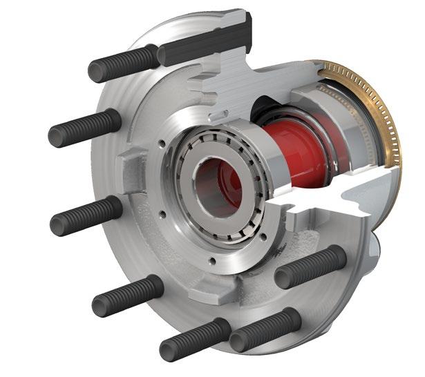
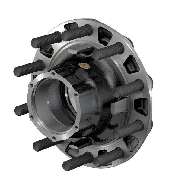
5 1. INTRODUCTION 1Introduction offers three types of wheel hubs: 1 ABS RING 2 Conventional hubs with manually-adjusted bearings PreSet hub assemblies with pre-adjusted bearings PreSet Plus hub assemblies with pre-adjusted bearings and an integrated spindle nut Conventional Hubs conventional hubs feature precision-machined aluminum or iron castings and are available in steer, drive and trailer configurations. Hubs are supplied with bearing cups and studs installed. Bearing cones and wheel seals are supplied by the customer. Bearings must be adjusted manually. See TMC RP618 for specifics of adjustment procedures. 1 ABS RING OIL SEAL INNER BEARING CONE INNER BEARING CUP OUTER BEARING CONE OUTER BEARING CUP PreSet Hub and Components FIGURE 2 PreSet Plus Hub Assemblies OIL SEAL INNER BEARING CONE INNER BEARING CUP SPACER (SECTIONED) LUBRICANT FILL PLUG a PreSet Plus hub assemblies feature the same PreSet technology and include the same precision-machined hubs, premium seals and specially toleranced roller bearings. However, PreSet Plus hubs incorporate the following: An integrated spindle nut that eases installation and disassembly and protects components during wheel end service 3 4 MACHINED STEER HUB Steer Hub and Components FIGURE 4 NOTE: CAN BE WITH OR WITHOUT AXLE STUDS. MACHINED DRIVE HUB PRESET PRESET PLUS COMPONENTS COMPONENTS a PRESET COMPONENTS PRESET PLUS COMPONENTS c Drive Hub and Components FIGURE 5 OUTER BEARING CONE OUTER BEARING CUP LUBRICANT FILL PLUG Conventional Hub and Components FIGURE 1 PreSet Hub Assemblies a PreSet hub assemblies include precision-machined hubs, premium seals, specially toleranced roller bearings and unique precision-machined bearing spacers. This combination eliminates the need to manually adjust wheel end play. These components are delivered as a complete assembly, reducing the potential for premature failures due to incorrect end play settings and/or improper installation practices. 1 An optimized spacer Standard magnetic fill plug INTEGRATED NUT OUTER BEARING CONE OUTER BEARING CUP ABS RING OIL SEAL INNER BEARING CONE INNER BEARING CUP SPACER (SECTIONED) LUBRICANT FILL PLUG a PreSet Plus Hub and Components FIGURE 3 5 MACHINED TN TRAILER HUB PRESET COMPONENTS PRESET PLUS COMPONENTS c TN Trailer Hub and Components FIGURE 6 MACHINED TP TRAILER HUB PRESET PRESET PLUS COMPONENTS COMPONENTS c TP Trailer Hub and Components FIGURE 7 Consolidated Metco, Inc. 1
6 Inspection HAZARD ALERT MESSAGES Read and observe all hazard alert messages in this publication. They provide information that can help prevent serious personal injury, damage to components, or both. Do not work under a vehicle supported only by jacks. Jacks can slip and fall over. Serious personal injury and damage to components can result. Park the vehicle on a level surface. Block the wheels to prevent the vehicle from moving. Support the vehicle with safety stands. To prevent serious eye injury, always wear safe eye protection when you perform vehicle maintenance or service. WHEEL END INSPECTION GENERAL GUIDELINES Operating temperature can be checked as the vehicle enters the service area following a normal run. If the hub is running in excess of 150 F above the ambient temperature in normal operating conditions, service is required. Wheel end service and maintenance requirements will vary based on vehicle operating conditions, vehicle specifications, lubrication type, and vehicle performance history. Consolidated Metco recommends the maintenance schedule below, in conjunction with TMC RP631A, to be adjusted as needed for varying conditions. If any item is found to be out of specification during any of the inspection steps listed below, place the vehicle out of service until the item can be repaired or replaced. 2. INSPECTION Driver Pre-Trip Visual Inspection Visually inspect the vehicle prior to operation. Include the following items: 1. Check for loose, damaged, or missing fasteners on the wheel and hub cap or axle. Rust or dark streaks coming from the wheel bolts may be a sign of improper wheel bolt torque. 2. Check for loose, damaged, or missing hubcaps. 3. Check for lubricant leaks at: Hubcap Drive axle flange gasket Oil fill plug Oil seal leakage indicated by lubricant on the hub, brake components or inside of the wheel 4. Check lubricant condition via hub cap window on steer and trailer hubs. Lubricant that is darkened, milky, shows water in it, or has large metallic particles in it is indicative of contamination or a part failure and must be replaced. Contaminated lubricant may be an indication of a leaking seal that should be replaced. 5. Check for insufficient lubricant level via hub cap window on steer and trailer hubs. Refill lubricant to the indicated fill level if required. If any of the above conditions are found, place the vehicle out of service until the item can be repaired. In Route Inspections 1. After making an in route stop, walk around the vehicle and inspect the hubs for any leaks (per item 3 under Driver Pre-Trip) and significant differences in temperature or excessive temperature. If excessive temperature is found, inspect and repair the wheel end as necessary. High temperatures and high loads may cause early bearing failure. Lubricant viscosity should be chosen based on expected operating temperatures. Preventative Maintenance Schedule During any routine preventative maintenance on the vehicle or axle (see your OEM guidelines and associated federal regulations), inspect the following items: 1. Check for loose, damaged, or missing fasteners on the wheel and hub cap. Rust or dark streaks coming from the wheel bolts may be a sign of improper wheel bolt torque. 2. Check for loose, damaged, or missing hubcaps. 3. Check for lubricant leaks at: Hubcap Drive axle flange gasket Oil fill plug Oil seal indicated by lubricant on the hub, brake components or inside of the wheel 4. Check for insufficient lubricant level via hub cap window on steer and trailer hubs. Refill lubricant to the indicated fill level if required. 2 Consolidated Metco, Inc.
7 2. INSPECTION (CONTINUED) 5. Check the lubricant condition. Lubricant that is darkened, milky, shows water in it or has large metallic particles in it is indicative of contamination or a part failure and must be replaced. Contaminated lubricant may be an indication of a leaking seal that should be replaced. On oil lubricated hubs equipped with a fill plug in the hubcap or barrel of the hub, place a magnet (or inspect the magnetic fill plug) in the lubricant and check for signs of large metallic particles picked up by the magnet. On drive axles, it is normal to find a small amount of very fine metallic particles from the carrier housing on the magnetic fill plug. These particles should be removed from the magnet anytime the plug is removed for inspection. If larger particles or chunks of metal are found, the hub should be removed from the spindle and the bearings and other components should be inspected for signs of damage or excessive wear. In vehicles without a fill plug in drive hubs inspect the lubricant volume and condition from the fill plug in the axle carrier housing. For vehicles lubricated with semi-fluid grease, inspect annually or every 100,000 miles. First, remove the hubcap and inspect the lubricant condition and volume. Verify the lubricant covers the ends of the bearing rollers. If the lubricant condition is good, add lubricant through the fill plug in the barrel of the hub to cover the ends of the bearing rollers. If the lubricant has a dry and caked appearance, remove the wheel end from the vehicle and clean and inspect all components. Replace damaged or worn components as necessary. Refill hub with semi-fluid grease amount per chart on page If regular schedule maintenance requires wheels/axle to be lifted, perform steps 7 and Lift and support the axle (see figure 8). Rotate the wheel. Check that the wheel rotates freely and smoothly. Listen and feel for any signs of rough bearing operation or vibration. Figure FIGURE 8 8. Place your hand on the top of the tire and use a pry bar to lift the bottom of the tire to check for loose bearings or chucking (see figure 9). If excess movement or chucking is found, wheel end service is required a Before you check for chucking, be sure to grease the king pins a FIGURE 9 If any of the above conditions are found, place the vehicle out of service until the item can be repaired. Service Interval Inspection results at driver pre-trip, in-route and preventative maintenance will indicate whether further service is required. When inspections indicate that service is necessary, follow the recommended service, inspection, reassembly and reinstallation instructions found in the following sections of this manual. Lubrication Analysis Beyond the recommended visual inspection and inspection with a magnet, develop a lubrication testing and replacement program. This program will depend on vehicle application, and lubrication type. A lubricant supplier should be consulted for additional lubricant inspection and testing recommendations. Consolidated Metco, Inc. 3
8 Identification WHEEL MOUNTING SYSTEMS wheel hubs are available in both hub pilot and ball seat nut configurations. Hub Pilot Wheel Mounting The hub pilot wheel mounting system makes use of a single two-piece flange nut on each wheel stud for both single and dual wheel applications (see figure 10). The hub pilot wheel mounting system is also known as the Uni-Mount-10 (10 stud), WHD-10 (10 stud), WHD-8 (8 stud), and ISO system. 8 SINGLE DUAL a Hub Pilot Mounting Systems FIGURE 10 Ball Seat Wheel Mounting System The ball seat wheel mounting system makes use of the spherical contact area between the nut and wheel to both locate the wheel and hold the wheel tight against the brake drum (see figure 11). The ball seat wheel mounting system is also known as the stud piloted, ball seat cap nut (BCN) and double cap nut (DCN) system. 3. IDENTIFICATION IDENTIFYING CONMET HUB ASSEMBLIES Identifying your hub assembly is important for many reasons. It will enable you to properly service the hub assembly and purchase the appropriate replacement parts if needed. Plus, if a warranty issue arises, you ll then be able to provide details on all aspects of the hub. This section is devoted to finding and understanding the different identification numbers associated with hubs. Vehicle Identification Number (VIN) The quickest and easiest method of identifying your hub assembly is to note the vehicle identification number (VIN) and call the truck dealership. The dealership can then tell you what hubs were installed on your vehicle. If this is not possible, there is a variety of identification numbers located on a hub assembly. Casting Number This number is physically cast into the hub and appears in large characters usually on the back side of the mounting flange near the stud head (see figure 12). 10 Machining Number This number is stamped on one of the following: Mounting flange face (see figure 13) Diameter of the mounting flange (see figure 14) Back side of the mounting flange (see figure 15) Barrel of the hub (see figure 16) The machining number represents the way the hub is machined (e.g., hub pilot vs. ball seat, 8.78" vs. 8.53" vs. 9" brake drum pilot diameter) MOUNTING FLANGE FACE Mounting Flange Face FIGURE 13 MOUNTING FLANGE DIAMETER a b Mounting Flange Diameter FIGURE 14 9 SINGLE DUAL CASTING NUMBER ON THE BACK SIDE OF THE MOUNTING FLANGE a 13 MOUNTING FLANGE BACKFACE Casting Number on the Back Side of the Mounting Flange FIGURE a Ball Seat Mounting Systems FIGURE a Mounting Flange Backface FIGURE 15 4 Consolidated Metco, Inc.
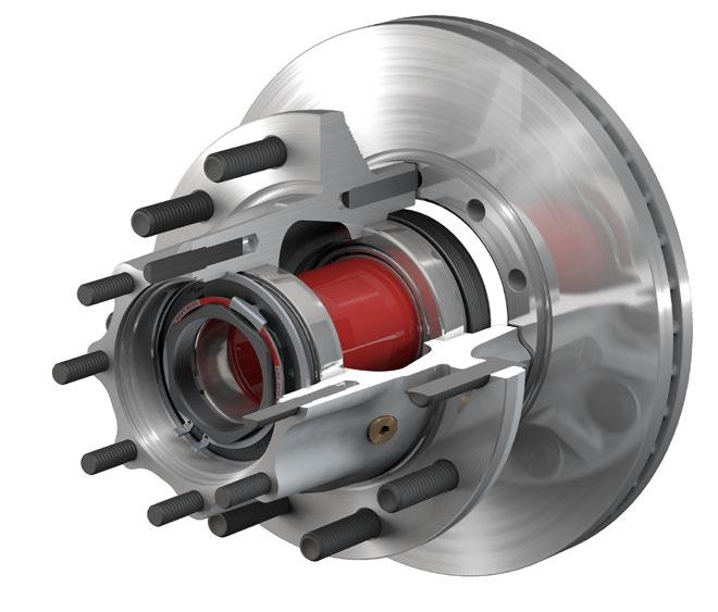
9 3. IDENTIFICATION (CONTINUED) 14 BARREL OF HUB a Barrel of Hub FIGURE 16 Conventional Hubs Conventional Wheel Hubs For instructions on installing s Conventional hub (see figure 17), refer to the Conventional reinstallation instructions in section PreSet Plus Hub Assemblies PreSet Plus Wheel Hubs For instructions on installing s PreSet Plus hub assemblies (see figure 19), refer to the PreSet hub assembly reinstallation instructions in section Final Hub Assembly Number This number is stamped on one of the following: Mounting flange face (see figure 13) PreSet Plus Hub Assembly FIGURE 19 Diameter of the mounting flange (see figure 14) Back side of the mounting flange (see figure 15) The final hub assembly number identifies the hub assembly, hub machining, studs, bearings, spacer, seal and ABS ring. Julian Date The casting, machining, and the final assembly have Julian dates stamped into the hub assembly in the same location as the assembly numbers (see figures 13, 14, 15 and 16). A Julian date appears as the day of the year plus the last two digits of the calendar year (e.g., July would appear as 18508). This number provides the date when the hub was machined and assembled at the factory and may be used for warranty purposes. Conventional Hub FIGURE 17 PreSet PreSet Hub Wheel Assemblies Hubs For instructions on installing s PreSet hub assemblies (see figure 18), refer to the PreSet hub reinstallation instructions in section PreSet Hub Assembly FIGURE 18 Consolidated Metco, Inc. 5
10 CONVENTIONAL Conventional WHEEL Wheel HUBS Hubs RECOMMENDED Recommended SERVICE Service 4. CONVENTIONAL WHEEL HUBS RECOMMENDED SERVICE Recommended Service Conventional Hubs conventional hubs feature precision-machined aluminum or iron castings and are available in steer, drive and trailer configurations. Hubs are supplied with bearing cups and studs installed. Bearing cones and seal are supplied by the customer. Bearings must be adjusted manually. See TMC RP618 specifics of adjustment procedures. 18 OUTER BEARING CONE OUTER BEARING CUP Conventional Hub and Components FIGURE 20 When inspections indicate that service is necessary on a conventional hub, follow the recommended service, inspection, reassembly and reinstallation instructions found in the following section. HUB REMOVAL AND DISASSEMBLY ABS RING OIL SEAL INNER BEARING CONE INNER BEARING CUP LUBRICANT FILL PLUG 1. Park the vehicle on a level surface. Block the wheels to prevent the vehicle from moving a Vehicles on jacks can fall, causing serious personal injury or property damage. Never work under a vehicle supported by a jack without supporting the vehicle with stands and blocking the wheels. Wear safe eye protection. 3. Place safety stands under the trailer frame or under each axle spring seat (see figure 21). 19 FIGURE Remove the tire and wheel assembly using procedures specified by the wheel manufacturer (see figure 22). 20 FIGURE If the axle is equipped with spring brake chambers, carefully compress and lock the springs so that they cannot actuate (see figure 23) a a Sudden release of compressed air can cause serious personal injury and damage to components. Before you service a spring chamber, carefully follow the manufacturer s instructions to compress and lock the spring to completely release the brake. Verify that no air pressure remains in the service chamber before you proceed. 6. For drum brakes, remove the brake drum. Support the drum during the removal process to prevent damage to the components. For disc brakes, remove caliper per manufacturers recommended procedure. 22 If the hub to be disassembled is a drive hub, remove the drive axle shaft, and capture the oil (see figure 24). Removing the Drive Axle Shaft FIGURE Place a container under the hubcap, or drive axle shaft for a drive hub, to receive the draining oil, then remove the hubcap or drive axle shaft. Do not reuse the oil. Correctly dispose of the lubricant. 8. Examine the spindle nut to determine the type of locking system. Disengage the locking device a Do not loosen the axle spindle nuts by either striking them directly with a hammer, or striking a drift or chisel placed against them. Damage to the parts will occur causing possible loss of axle wheel-end components and serious personal injury. 9. Remove the spindle nut system. 2. Raise the axle until the tires are off the floor a FIGURE 23 6 Consolidated Metco, Inc.
11 CONVENTIONAL WHEEL HUBS RECOMMENDED SERVICE 4. CONVENTIONAL WHEEL HUBS RECOMMENDED SERVICE 10. Slide the hub off the spindle. Remove and save the outer bearing cone. Be careful when you remove the hub that you do not damage the outer bearing by dropping it on the floor. 23 If the hub is difficult to remove because the seal or bearings are stuck on the spindle, use a mechanical puller to remove the hub (see figure 25). If part of the seal remains on the spindle, carefully remove the part of the seal that remains on the spindle. FIGURE Place the hub on its outboard end and remove the seal. Retain the seal if it needs to be returned for warranty consideration. 12. Remove the inner bearing cone (see figure 26). 24 This can be done by striking the remaining portion of the seal with the round end of a ball-peen hammer. Use caution not to damage the seal journal on the spindle a COMPONENT INSPECTION AND REPLACEMENT HAZARD ALERT MESSAGES Read and observe all hazard alert messages in this publication. They provide information that can help prevent serious personal injury, damage to components, or both. To prevent serious eye injury, always wear safe eye protection when you perform vehicle maintenance or service. Observe all warnings and cautions provided by the press manufacturer to avoid damage to components and serious personal injury. Do not hit steel parts with a steel hammer. Pieces of a part can break off. Serious personal injury and damage to components can result. Use a brass or synthetic mallet for assembly and disassembly procedures. Solvent cleaners can be flammable, poisonous and cause burns. Examples of solvent cleaners are carbon tetrachloride, and emulsion-type and petroleum-base cleaners. Read the manufacturer s instructions before using a solvent cleaner, then carefully follow the instructions. Also follow the procedures below. Wear safe eye protection. Wear clothing that protects your skin. Work in a well-ventilated area. Do not use gasoline or solvents that contain gasoline. Gasoline can explode. You must use hot solution tanks or alkaline solutions correctly. Read the manufacturer s instructions before using hot solution tanks and alkaline solutions. Then carefully follow the instructions. CLEAN AND DRY COMPONENTS Worn or Damaged Components Do not repair or recondition wheel-end components. Replace damaged, worn or out-of-specification components. Do not mill or machine any components. Using repaired, reconditioned, damaged or worn components can cause wheel end failure, which can result in serious injury and property damage. Hub and Component Cleaning 1. Use a cleaning solvent to clean the hub and all wheel end components. 2. Do NOT clean ground or polished parts in a hot solution tank or with water, steam or alkaline solutions. These solutions will cause corrosion of the parts. 3. Clean and inspect the wheel bearing cups and cones, race, spindle bearing and seal journals on the spindle and hub. Bearings should be cleaned with clean filtered solvent and dried with either compressed air or a lint-free rag. If compressed air is used, do not spin dry the bearings. The rollers may score due to lack of lubricant and rollers could come off which can result in serious injury. Ensure that the air line is moisture free. 4. Clean and inspect the spindle. Be sure to clean the full length of the seal journal on the spindle. Conventional Wheel Hubs Recommended Service CONVENTIONAL WHEEL HUBS RECOMMENDED SERVICE INNER BEARING CONE b Hub Disassembly FIGURE 26 Do not use hot solution tanks or water and alkaline solutions to clean ground or polished parts. Damage to parts can result. 5. Parts must be dried immediately after cleaning. Dry parts with clean paper towels or rags, or compressed air. Do not dry bearings by spinning with compressed air. Consolidated Metco, Inc. 7
12 CONVENTIONAL Conventional WHEEL Wheel HUBS Hubs - RECOMMENDED Recommended SERVICE Service 4. CONVENTIONAL WHEEL HUBS RECOMMENDED SERVICE 6. Apply a light oil to cleaned and dried parts that are not damaged and are to be immediately assembled. Use only the type of oil used by the manufacturer. Do NOT apply oil to the brake linings or the brake drums. 7. If the parts are to be stored, apply a good corrosion preventative to all surfaces. Do NOT apply the material to the brake linings or the brake drums. Store the parts inside special paper or other material that prevents corrosion. INSPECTING BEARING CUPS AND CONES If you choose to reuse existing bearings at this service, they must be inspected in accordance with the bearing manufacturers recommended guidelines. If this inspection indicates that existing bearing component(s) must be replaced, bearing cups and cones must be replaced as a set. After components have been properly cleaned, visually inspect the cups and cones for any wear or damage. Reference TMC RP644 for proper component inspection procedures. REMOVING CUPS IN ALUMINUM HUBS 1. If the bearing cup must be removed from an aluminum hub, remove it by welding a large bead around the bearing surface of the steel cup, letting the assembly cool, and removing the bearing cup (see figure 27). 25 If a welder is not available, heat the hub in an oven to a temperature not to exceed 300 F and pound out the bearing cups with a hammer and mild steel bar, being careful not to damage the hub a Welding Bead FIGURE Inspect the bearing cup bore for evidence of cup rotation or spun cups. If cup rotation exists, replace the hub. REMOVING CUPS IN IRON HUBS 1. On an iron hub, remove the bearing cup using a large hammer and a mild steel bar or a hydraulic press. Take precaution to avoid damaging the bearing cup bore and shoulder. 2. Inspect the bearing cup bore for evidence of cup rotation or spun cups. If cup rotation exists, replace the hub. INSTALLING A NEW CUP IN ALUMINUM HUBS To install a new cup in an aluminum hub, it is recommended that the hub be heated in boiling water (212 F) or in an oven at a temperature not to exceed 300 F. Cooling the cup in a freezer to 32 F or below will further ease the installation. Remove the aluminum hub from the oven or water and carefully drop in the new bearing cup being certain it is fully seated. If the cup is loose, allow a few seconds for it to heat up and secure itself before moving the hub. Use a to feeler gauge to ensure the cup is fully seated against the shoulder of the bearing bore. INSTALLING A NEW CUP IN IRON HUBS Iron hubs do not need to be heated for bearing cup installation. Press the bearing cup into the hub, being certain that it is fully seated (see figure 28). Use a to feeler gauge to ensure the cup is fully seated against the shoulder of the bearing bore. 26 Do not overheat the hub as it may degrade the heat-treated strength of the hub. Do not heat the hub with a torch or open flame a Bearing Cup Pressed into Hub FIGURE 28 8 Consolidated Metco, Inc.
13 4. CONVENTIONAL WHEEL HUBS RECOMMENDED SERVICE WHEEL STUDS Replace all wheel studs that have damaged or distorted threads, are broken or bent, or are badly corroded. Also, replace both studs adjacent to the damaged stud. If two or more studs have damage, replace all the studs in the hub. Broken studs are usually an indication of excessive or inadequate wheel nut torque. STUD REMOVAL Observe all warnings and cautions for press operation provided by the press manufacturer to avoid serious personal injury and damage to components. 1. Place the clean hub in a shop press with the hub supported evenly around and adjacent to the stud being removed. Failure to adequately support the hub can result in physical injury and/or damage to the hub. Some hubs are configured so it is impractical to have supports to prevent the hub from tipping when force is applied to the stud. In this case, support the hub on wood blocks on the floor and use a heavy hammer to drive the studs out with several sharp blows. Be careful to avoid damaging the hub and components, particularly the seal bore and the ABS tone ring. 2. Press the stud out of the hub. STUD REPLACEMENT On the ball seat wheel mounting system, always use left-handed threaded studs, which are gold in color and have an L stamped on the end, in the hub on the driver s side of the equipment, and use right-handed threaded studs, which are silver in color and have an R stamped on the end, in the hub on the passenger s side of the equipment. The part number is located on the head of the stud. The same part number must be used for replacement unless changing the drum or wheel type. 1. To install a new stud, support the hub evenly around and adjacent to the stud being installed. 2. Press the new stud all the way into the hub. Be sure the stud is fully seated and that the stud head is not embedded into the hub. Excessive force can cause the stud head to be embedded into the hub, which can create a crack in the hub, resulting in serious injury and property damage. If a stud head is embedded in a hub, replace the hub. HUB, DRUM AND WHEEL INSPECTION 1. Inspect the drum pilots, wheel pilots, and mounting face on the hub for damage. A damaged drum pilot is usually caused by improper drum mounting. A damaged wheel pilot could be the result of inadequate wheel nut torque, allowing the wheels to slip in service. Also, inspect other surfaces of the hub for signs of cracks or damage. 2. Inspect the wheels and brake drum for damage. ABS TONE RING INSPECTION (AS APPLICABLE) The Anti-Lock Braking System (ABS) signals acts like any signal generator where the magnet passes a coil and generates a current. On hubs, the toothed ring passes a sensor and generates a signal that is sent to the ABS computer. There are three types of ABS rings used on hubs machined, stamped steel and bolt on (see figure 29). 27 Do not repair or recondition wheel-end components. Replace damaged, worn or out-of-specification components. Do not mill or machine any components. Using repaired, reconditioned, damaged or worn components can cause wheel end failure, which can result in serious injury and property damage. MACHINED ABS RING BOLT ON ABS RING STAMPED STEEL ABS RING b FIGURE 29 If the tone ring is damaged (for example, if it is dropped, bent, chipped or dinged), it must be replaced. For a list of replacement ABS rings, refer to the Service Parts List in the back of this section. Conventional Wheel Hubs - Recommended Service CONVENTIONAL WHEEL HUBS RECOMMENDED SERVICE Consolidated Metco, Inc. 9
14 CONVENTIONAL Conventional WHEEL Wheel HUBS Hubs - RECOMMENDED Recommended SERVICE Service 4. CONVENTIONAL WHEEL HUBS RECOMMENDED SERVICE REMOVAL AND INSTALLATION OF MACHINED ABS TONE RING For a machined ring, remove using a chisel, making sure not to damage the hub (see figure 30). Reinstall by heating the ring to 350 F in an oven and installing it on the hub. 28 Machined ABS Ring FIGURE 30 REMOVAL AND INSTALLATION OF STAMPED STEEL ABS TONE RING 1. The steer axle tone ring can be removed by gripping the ring with a pair of locking pliers and tapping the pliers upward with a rubber mallet. Work around the ring to keep the ring from cocking (see figure 31). Drive axle and trailer tone rings can be removed by gripping the ring with a pair of locking pliers and prying against the head of a wheel stud to lift the ring off the hub. Work around the ring to prevent cocking (see figure 32) a 30 Stamped Steel ABS Ring FIGURE Thoroughly clean and degrease the ABS ring seat on the hub with a nonflammable solvent. 3. Place the hub in a press and place the ABS ring on the hub ring seat. 4. Using ring installation tool (part number ), center the tool over the ABS ring. Each type of ring fits a corresponding diameter on the tool (see figure 33). 31 Replace the hub if the ABS ring seat is damaged. The ABS ring must be fully seated with a maximum of axial runout to ensure the ABS system functions properly. For steer hubs, be certain the inside diameter flange is facing up a 5. Press the ring on the hub. If a press is not available, drive the ring on with a hammer or mallet until the ring seats on the hub (see figure 34). A swift initial blow with an 8-lb. hammer may be necessary to start the ring onto the hub. 32 Using a Hammer to Install the Ring FIGURE Inspect the ring to ensure proper seating. If the ring is not completely seated, continue to drive the ring with the ring installation tool until it is completely seated. REMOVAL AND INSTALLATION OF BOLT ON ABS TONE RINGS 1. Remove and discard the fasteners holding the ABS tone ring on the hub. 2. Thoroughly clean and degrease the ABS ring seat on the hub with a non-flammable solvent. 3. Install the new ABS ring using the new fasteners included with the ring. Torque the fasteners to the torque specifications below. Figure a a Stamped Steel ABS Ring FIGURE a Installing the ABS Tone Ring FIGURE 33 Thread Size Torque # in-lbs 1/4" in-lbs 10 Consolidated Metco, Inc.
15 4. CONVENTIONAL WHEEL HUBS REASSEMBLY Reassembly CONVENTIONAL WHEEL HUBS REASSEMBLY 1. Place the hub, seal end up, on a clean work bench surface. 2. Lubricate the inner bearing cone with the same lubricant as will be used in the hub and install it into the inner bearing cup (see figure 35). 33 When using an oil bath system, do not pack the bearing with grease. Grease will prevent the proper circulation of axle lubricant and can cause premature wheel seal and bearing failure a Bearing Cone Assembly FIGURE 35 Seal Installation Tools Axle Type Part Number FF Steer FL Steer R-Drive TN-Trailer TP-Trailer Flat Plate Dimensions Seal Part Min. Max. Application Number Dia. Dia. FF Steer " 4.65" FL Steer " 5.4" R-Drive " 5.85" TN-Trailer " 5.85" TP-Trailer " 5.85" 4. When installing the seal, tap the adapter plate of the installation tool around the outer edge to position the seal. Drive the wheel seal into place (see figure 36). Once the tool bottoms out, the seal is installed correctly Lubricate the inner diameter of the seal with a light film of the same lubricant as will be used in the hub. 7. Turn the hub over, and place it seal end down. 8. Lubricate the outer bearing cone with the same lubricant as will be used in the hub and install it into the hub assembly (see figure 37) a Installing the Outer Bearing Cone FIGURE 37 Conventional Wheel Hubs - Reassembly Recommended Service CONVENTIONAL WHEEL HUBS REASSEMBLY The seal must be replaced every time the hub is removed from the spindle. Do not apply any gasket sealant to the seal outer or inner diameter. Always use the seal installation tool specified by the seal manufacturer. Using an improper tool can distort or damage the seal and cause premature seal failure. 3. Position the seal into the hub bore. Use a seal installation tool or flat plate and a small mallet to install the seal. CONMET SEAL c Seal Installation FIGURE Check to be certain the seal is not cocked and that the seal inner diameter and the inner bearing turn freely. seals require the proper tool for installation. Refer to the tables below for a seal installation tool or flat plate dimensions. For other seals, refer to the specific manufacturers instructions. Failure to lubricate the inner diameter of the seal may result in premature seal failure. Consolidated Metco, Inc. 11
16 CONVENTIONAL Conventional WHEEL Wheel HUBS Hubs REINSTALLATION Reinstallation 4. CONVENTIONAL WHEEL HUBS REINSTALLATION Reinstallation INSTALLING CONVENTIONAL WHEEL HUBS Spindle Preparation 1. Clean the spindle to remove any lubricant, corrosion prevention coating, foreign material, or surface rust that may be present. Be sure to clean the full length of the seal journal. 2. Lubricate the bearing journals on the spindle, or the inside diameter of the bearing cones with Grade 2 grease or the lubricant that will be used in the wheel end. Do not coat the seal journal on the spindle. 3. Lubricate the inside diameter of the seal with the same lubricant that will be used in the wheel end. The following service procedures apply to steer, drive, and trailer axle assemblies using conventional double nut or single nut systems. For self-locking single nut systems, consult manufacturers instructions. 1. Lubricate the bearings with clean lubricant of the same type used in the axle sump or hub assembly. 2. Install the wheel hub and bearing onto the axle spindle with a smooth, firm motion. Use care to maintain alignment between the bearing cones, and spindle to avoid seal damage. Torque the inner adjusting nut to 200 ft-lbs while rotating the hub assembly. 3. Back off the inner adjusting nut one full turn. Rotate the hub. 8. Use a dial indicator to verify acceptable endplay of 0.001"-0.005". If end play is not within specification, readjustment is required. Be sure to install or activate any locking device. This information is intended for reference only. Consolidated Metco inc. does not assume any liablity in the event of improper use or mismatch of components. For additional information, see TMC RP618. Failure to apply lubricant to the bearing journals will result in fretting corrosion, which may result in difficulty removing the bearing. Never support the hub on the spindle with just the inner bearing and seal. This can damage the seal and cause premature failure, i.e, by cocking the seal in the bore. Conventional Hub Installation 4. Re-torque the inner adjusting nut to 50 ft-lbs while rotating the wheel hub assembly. 5. Back off the inner adjustment nuts as per the Manual Bearing Adjustment Procedure table (next page). 6. Install the locking washer. Existing spindle nuts can be re-used as long as they are in good condition. Do not re-use a spindle nut that is worn or pitted on its face or threads. If dowel pin and washer (or washer tang and nut flat) are not aligned, remove the washer, turn it over, and reinstall. If required, loosen the inner (adjusting) nut just enough for alignment. See TMC RP618 for more details regarding installation of wheel hubs with manual adjusted bearing systems. Bendable type washer lock only: Secure nuts by bending one wheel nut washer tang over the inner and outer nut. Bend the tangs over the closest flat perpendicular to the tang. 7. Install and torque the outer jam nut as per chart on next page. 12 Consolidated Metco, Inc.
17 4. CONVENTIONAL WHEEL HUBS REINSTALLATION Manual Bearing Adjustment Procedure (reference TMC RP618) Axle Type Steer (front non-drive) Axle Spindle Threads per Inch Spindle Nut Type 12 Single Nut with Cotter 18 Pin Double Nut System With Bendable Tang Washer or Dowel Pin and Washer Drive 12 Double Nut System 16 Dowel Pin and Washer 12 Double Nut System 16 with Bendable Tang Washer Trailer 12 Double Nut System 16 with Bendable Tang Washer or Dowel Pin and Washer Final Spindle Nut Backoff Jam Nut Torque (ft-lbs) 1/6 Turn Install Cotter Pin to 1/4 Turn Lock Spindle Nut into Position (from step 6) 1/3 Turn /2 Turn 1/4 Turn /4 Turn /4 Turn Conventional Wheel Hubs Reinstallation CONVENTIONAL WHEEL HUBS REINSTALLATION Consolidated Metco, Inc. 13
18 CONVENTIONAL Conventional WHEEL Wheel HUBS Hubs SERVICE Service PARTS Parts Service Parts Axle Designations 4. CONVENTIONAL WHEEL HUBS SERVICE PARTS Designation Typical Axle Rating (lbs) Comments Steer Axle FC Steer 8,000 Medium duty FF Steer 12,000-14,700 Standard linehaul axle. Comes in two spindle variations. 1. Flat locking feature with 12 threads/inch. 2. Keyway locking feature with 18 threads/inch. FL Steer 20,000 Vocational applications Drive Axle L-Drive 19,000 Medium duty R-Drive 20,000-23,000 Standard linehaul axle Trailer Axle TN Trailer 22,500 Tapered spindle TP Trailer 25,000 Parallel spindle or "Propar" NOTE: These axle ratings are to be used as a reference only. Refer to the vehicle's door plate for your specific application. Seals Position Spindle Type Aftermarket Part Number Steer FF Spindle FL Spindle Drive R Spindle Trailer TP Spindle TN Spindle Seal Installation Tools Axle Designation Installation Tool Part Number Min. Dia.* Max. Dia.* FF Steer " 4.65" FL Steer " 5.4" R-Drive TN Trailer " 5.85" TP Trailer *Required flat plate dimensions if you are not using a installation tool (minimum of 3/8", 9.5 mm thick). 14 Consolidated Metco, Inc.
19 4. CONVENTIONAL WHEEL HUBS SERVICE PARTS Approved Conventional Aftermarket Bearings Description Number Bearing Set Number FC Steer Axle Inner Cup & Cone Outer Cup & Cone Not available in sets FF Steer Axle Inner Cup & Cone Set 413 Outer Cup & Cone Set 406 FL Steer Axle Inner Cup & Cone Set 423 Outer Cup & Cone Set 424 L-Drive Axle Inner Cup & Cone Outer Cup & Cone Not available in sets R-Drive Axle Inner Cup & Cone Set 403 Outer Cup & Cone Set 401 TN Trailer Axle Inner Cup & Cone Set 414 Outer Cup & Cone Set 413 TP Trailer Axle Inner Cup & Cone Set 415 Outer Cup & Cone Set 415 Conventional Wheel Hubs Service Parts CONVENTIONAL WHEEL HUBS SERVICE PARTS Consolidated Metco, Inc. 15
20 CONVENTIONAL Conventional WHEEL Wheel HUBS Hubs SERVICE Service PARTS Parts 4. CONVENTIONAL WHEEL HUBS SERVICE PARTS ABS Rings for Hubs (for reference only) Axle Material Type of Brake Hub Casting Number ABS Ring Part Number FC Steer Iron Drum FF Steer FL L-Drive (190) R-Drive Aluminum Iron Disc Drum Disc Drum Aluminum Drum Iron Disc Disc Iron Drum Aluminum Iron Disc Drum Drum TN Aluminum Drum TP Aluminum Disc Drum Iron Drum If an ABS ring is not listed for a particular hub, contact Customer Service at Consolidated Metco, Inc.
21 5. PRESET WHEEL HUBS RECOMMENDED SERVICE Recommended Service PreSet Hub Assemblies PreSet hub assemblies include precision-machined hubs, premium seals, specially toleranced roller bearings and unique precision-machined bearing spacers. This combination eliminates the need to manually adjust wheel end play. These components are delivered as a complete assembly, reducing the potential for premature failures due to incorrect end play settings and/or improper installation practices. 1 OUTER BEARING CONE OUTER BEARING CUP ABS RING OIL SEAL INNER BEARING CONE INNER BEARING CUP SPACER (SECTIONED) LUBRICANT FILL PLUG a PreSet Hub and Components FIGURE 38 When inspections indicate that service is necessary on a PreSet Hub, follow the recommended service, inspection, reassembly and reinstallation instructions found in the following section. HUB REMOVAL AND DISASSEMBLY 1. Park the vehicle on a level surface. Block the wheels to prevent the vehicle from moving. 2. Raise the axle until the tires are off the floor. 3. Place safety stands under the trailer frame or under each axle spring seat (see figure 39). 2 Vehicles on jacks can fall, causing serious personal injury or property damage. Never work under a vehicle supported by a jack without supporting the vehicle with stands and blocking the wheels. Wear safe eye protection a FIGURE Remove the tire and wheel assembly using procedures specified by the wheel manufacturer (see figure 40). 5. If the axle is equipped with spring brake chambers, carefully compress and lock the springs so that they cannot actuate (see figure 41). 4 Sudden release of compressed air can cause serious personal injury and damage to components. Before you service a spring chamber, carefully follow the manufacturer s instructions to compress and lock the spring to completely release the brake. Verify that no air pressure remains in the service chamber before you proceed a FIGURE For drum brakes, remove the brake drum. Support the drum during the removal process to prevent damage to the components. For disc brakes, remove caliper per manufacturers recommended procedure. PreSet Wheel Hubs Recommended Service PRESET WHEEL HUBS RECOMMENDED SERVICE In order to ensure optimum wheel hub performance, recommends that only approved PreSet service parts be used to replace all critical components of the system. Refer to the back of this section for a listing of approved parts a 5 If the hub to be disassembled is a drive hub, remove the drive axle shaft, and capture the oil (see figure 42). FIGURE a Removing the Drive Axle Shaft FIGURE 42 Consolidated Metco, Inc. 17
22 PRESET PreSet WHEEL Wheel HUBS Hubs RECOMMENDED Recommended SERVICE Service 5. PRESET WHEEL HUBS RECOMMENDED SERVICE 7. Place a container under the hubcap, or drive axle shaft for a drive hub, to receive the draining oil, then remove the hubcap or drive axle shaft. Do not reuse the oil. Correctly dispose of the lubricant. 8. Examine the spindle nut to determine the type of locking system. Disengage the locking device. Do not loosen the axle spindle nuts by either striking them directly with a hammer, or striking a drift or chisel placed against them. Damage to the parts will occur causing possible loss of axle wheel-end components and serious personal injury. 9. Remove the spindle nut system. 10. Slide the hub off the spindle. Remove and save the outer bearing cone. Be careful when you remove the hub that you do not damage the outer bearing by dropping it on the floor. If the hub is difficult to remove because the seal or bearings are stuck on the spindle, use a mechanical puller to remove the hub (see figure 43). If part of the seal remains on the spindle, carefully remove the part of the seal that remains on the spindle. 6 FIGURE Place the hub on its outboard end and remove the seal. Retain the seal if it needs to be returned for warranty consideration. 12. Remove the inner bearing cone and spacer (see figure 44). 7 This can be done by striking the remaining portion of the seal with the round end of a ball-peen hammer. Use caution not to damage the seal journal on the spindle. INNER BEARING CONE SPACER c a Hub Disassembly FIGURE 44 COMPONENT INSPECTION AND REPLACEMENT HAZARD ALERT MESSAGES To prevent serious eye injury, always wear safe eye protection when you perform vehicle maintenance or service. Observe all warnings and cautions provided by the press manufacturer to avoid damage to components and serious personal injury. Do not hit steel parts with a steel hammer. Pieces of a part can break off. Serious personal injury and damage to components can result. Use a brass or synthetic mallet for assembly and disassembly procedures. Solvent cleaners can be flammable, poisonous and cause burns. Examples of solvent cleaners are carbon tetrachloride, and emulsion-type and petroleum-base cleaners. Read the manufacturer s instructions before using a solvent cleaner, then carefully follow the instructions. Also follow the procedures below. Wear safe eye protection. Wear clothing that protects your skin. Work in a well-ventilated area. Do not use gasoline or solvents that contain gasoline. Gasoline can explode. You must use hot solution tanks or alkaline solutions correctly. Read the manufacturer s instructions before using hot solution tanks and alkaline solutions. Then carefully follow the instructions. Do not use hot solution tanks or water and alkaline solutions to clean ground or polished parts. Damage to parts can result. Read and observe all hazard alert messages in this publication. They provide information that can help prevent serious personal injury, damage to components, or both. 18 Consolidated Metco, Inc.
23 CLEAN AND DRY COMPONENTS 5. PRESET WHEEL HUBS RECOMMENDED SERVICE Worn or Damaged Components Do not repair or recondition wheel-end components. Replace damaged, worn or out-of-specification components. Do not mill or machine any components. Using repaired, reconditioned, damaged or worn components can cause wheel end failure, which can result in serious injury and property damage. Hub and Component Cleaning 1. Use a clean filtered solvent to clean the hub and all wheel end components. 2. Do NOT clean ground or polished parts in a hot solution tank or with water, steam or alkaline solutions. These solutions will cause corrosion of the parts. 3. Clean and inspect the wheel bearing cups and cones, race, spindle bearing and seal journals on the spindle and hub. Bearings should be cleaned with clean filtered solvent and dried with either compressed air or a lint-free rag. If compressed air is used, do not spin dry the bearings. The rollers may score due to lack of lubricant and rollers could come off which can result in serious injury. Ensure that the air line is moisture free. 4. Clean and inspect the spindle. Be sure to clean the full length of the seal journal on the spindle. 5. Parts must be dried immediately after cleaning. Dry parts with clean paper towels or rags, or compressed air. Do not dry bearings by spinning with compressed air. 6. Apply a light oil to cleaned and dried parts that are not damaged and are to be immediately assembled. Use only the type of oil used by the manufacturer. Do NOT apply oil to the brake linings or the brake drums. 7. If the parts are to be stored, apply a good corrosion preventative to all surfaces. Do NOT apply the material to the brake linings or the brake drums. Store the parts inside special paper or other material that prevents corrosion. INSPECTING BEARING CUPS AND CONES AND BEARING SPACER PreSet and PreSet Plus hubs use a precision-machined spacer in conjunction with specially toleranced bearings to control wheel end play. recommends installing a new PreSet/ PreSet Plus service kit when inspection indicates that component replacement is necessary. PreSet/PreSet Plus service kits are available from a parts dealer or distributor. If you choose to reuse existing bearings at this service, they must be inspected in accordance with the bearing manufacturers recommended guidelines. If this inspection indicates that existing bearing component(s) must be replaced, bearing cups and cones must be replaced as a set. Whenever new bearings are installed, replacement of the bearing spacer is also recommended. 1. After components have been properly cleaned, visually inspect the cups, cones and spacer for any wear or damage. Reference TMC RP644 for 8 proper component inspection procedures. Bearing spacers should be visually inspected for signs of wear or damage. Carefully inspect the machined ends of the bearing spacer. Wear to the bearing spacer can appear as a sharp ring of standing metal at either edge of the machined surfaces (see figure 45). Replace the spacer if it has visible wear evidenced by a raised edge on the machined end. NEW WORN SHARP EDGE Bearing Spacer Wear FIGURE If removal or replacement is required, follow the steps outlined below. REMOVING CUPS IN ALUMINUM HUBS a 1. If the bearing cup must be removed from an aluminum hub, remove it by welding a large bead around the bearing surface of the steel cup, letting the assembly cool, and removing the bearing cup (see figure 46). If a welder is not available, heat the hub in an oven to a temperature not to exceed 300 F and pound out the bearing cups with a hammer and mild steel bar, being careful not to damage the hub. PreSet Wheel Hubs Recommended Service PRESET WHEEL HUBS RECOMMENDED SERVICE Consolidated Metco, Inc. 19
24 PRESET PreSet WHEEL Wheel HUBS Hubs RECOMMENDED Recommended SERVICE Service 9 5. PRESET WHEEL HUBS RECOMMENDED SERVICE Welding Bead FIGURE Inspect the bearing cup bore for evidence of cup rotation or spun cups. If cup rotation exists, replace the hub. REMOVING CUPS IN IRON HUBS 1. On an iron hub, remove the bearing cup using a large hammer and a mild steel bar or a hydraulic press. Take precaution to avoid damaging the bearing cup bore and shoulder. 2. Inspect the bearing cup bore for evidence of cup rotation or spun cups. If cup rotation exists, replace the hub. INSTALLING A NEW CUP IN ALUMINUM HUBS To install a new cup in an aluminum hub, it is recommended that the hub be heated in boiling water (212 F) or in an oven at a temperature not to exceed 300 F. Cooling the cup in a freezer to 32 F or below will further ease the installation a Do not overheat the hub as it may degrade the heat-treated strength of the hub. Do not heat the hub with a torch or open flame. Remove the aluminum hub from the oven or water and carefully drop in the new bearing cup being certain it is fully seated. If the cup is loose, allow a few seconds for it to heat up and secure itself before moving the hub. Use a to feeler gauge to ensure the cup is fully seated against the shoulder of the bearing bore. INSTALLING A NEW CUP IN IRON HUBS Iron hubs do not need to be heated for bearing cup installation. Press the bearing cup into the hub, being certain that it is fully seated (see figure 47). Use a to feeler gauge to ensure the cup is fully seated against the shoulder of the bearing bore. 10 Bearing Cup Pressed into Hub FIGURE 47 WHEEL STUDS a Replace all wheel studs that have damaged or distorted threads, are broken or bent, or are badly corroded. Also, replace both studs adjacent to the damaged stud. If two or more studs have damage, replace all the studs in the hub. Broken studs are usually an indication of excessive or inadequate wheel nut torque. STUD REMOVAL Observe all warnings and cautions for press operation provided by the press manufacturer to avoid serious personal injury and damage to components. 1. Place the clean hub in a shop press with the hub supported evenly around and adjacent to the stud being removed. Failure to adequately support the hub can result in physical injury and/or damage to the hub. Some hubs are configured so it is impractical to have supports to prevent the hub from tipping when force is applied to the stud. In this case, support the hub on wood blocks on the floor and use a heavy hammer to drive the studs out with several sharp blows. Be careful to avoid damaging the hub and components, particularly the seal bore and the ABS tone ring. 2. Press the stud out of the hub. STUD REPLACEMENT On the ball seat wheel mounting system, always use left-handed threaded studs, which are gold in color and have an L stamped on the end, in the hub on the driver s side of the equipment, and use right-handed threaded studs, which are silver in color and have an R stamped on the end, in the hub on the passenger s side of the equipment. The part number is located on the head of the stud. The same part number must be used for replacement unless changing the drum or wheel type. 1. To install a new stud, support the hub evenly around and adjacent to the stud being installed. 2. Press the new stud all the way into the hub. Be sure the stud is fully seated and that the stud head is not embedded into the hub. 20 Consolidated Metco, Inc.
25 5. PRESET WHEEL HUBS RECOMMENDED SERVICE Excessive force can cause the stud head to be embedded into the hub, which can create a crack in the hub, resulting in serious injury and property damage. If a stud head is embedded in a hub, replace the hub. HUB, DRUM AND WHEEL INSPECTION 1. Inspect the drum pilots, wheel pilots, and mounting face on the hub for damage. A damaged drum pilot is usually caused by improper drum mounting. A damaged wheel pilot could be the result of inadequate wheel nut torque, allowing the wheels to slip in service. Also, inspect other surfaces of the hub for signs of cracks or damage. 2. Inspect the wheels and brake drum for damage. Do not repair or recondition wheel-end components. Replace damaged, worn or out-of-specification components. Do not mill or machine any components. Using repaired, reconditioned, damaged or worn components can cause wheel end failure, which can result in serious injury and property damage. 11 FIGURE 48 If the tone ring is damaged (for example, if it is dropped, bent, chipped or dinged), it must be replaced. For a list of replacement ABS rings, refer to the Service Parts List in the back of this section. REMOVAL AND INSTALLATION OF MACHINED ABS TONE RING For a machined metal ring, remove using a chisel, making sure not to damage the hub (see figure 49). Reinstall by heating the ring to 350 F in an oven and installing it on the hub. 12 MACHINED ABS RING BOLT ON ABS RING STAMPED STEEL ABS RING b REMOVAL AND INSTALLATION OF STAMPED STEEL ABS TONE RING 1. The steer axle tone ring can be removed by gripping the ring with a pair of locking pliers and tapping the pliers upward with a rubber mallet. Work around the ring to keep the ring from cocking (see figure 50). Drive axle and trailer tone rings can be removed by gripping the ring with a pair of locking pliers and prying against the head of a wheel stud to lift the ring off the hub. Work around the ring to prevent cocking (see figure 51) a Stamped Steel ABS Ring FIGURE 50 PreSet Wheel Hubs Recommended Service PRESET WHEEL HUBS RECOMMENDED SERVICE ABS TONE RING INSPECTION (AS APPLICABLE) The Anti-Lock Braking System (ABS) signals acts like any signal generator where the magnet passes a coil and generates a current. On hubs, the toothed ring passes a sensor and generates a signal that is sent to the ABS computer. There are three types of ABS rings used on hubs machined, stamped steel and bolt on (see figure 48) a Machined ABS Ring FIGURE a Stamped Steel ABS Ring FIGURE Thoroughly clean and degrease the ABS ring seat on the hub with a nonflammable solvent. Replace the hub if the ABS ring seat is damaged. The ABS ring must be fully seated with a maximum of 0.008ʺ axial runout to ensure the ABS system functions properly. Consolidated Metco, Inc. 21
26 PRESET PreSet WHEEL Wheel HUBS Hubs RECOMMENDED Recommended SERVICE Service 5. PRESET WHEEL HUBS RECOMMENDED SERVICE 3. Place the hub in a press and place the ABS ring on the hub ring seat. 4. Using ring installation tool (part number ), center the tool over the ABS ring. Each type of ring fits a corresponding diameter on the tool (see figure 52). 15 For steer hubs, be certain the inside diameter flange is facing up. 6. Inspect the ring to ensure proper seating. If the ring is not completely seated, continue to drive the ring with the ring installation tool until it is completely seated. REMOVAL AND INSTALLATION OF BOLT ON ABS TONE RINGS (For Disc Brakes) 1. Remove and discard the fasteners holding the ABS tone ring on the hub. 2. Thoroughly clean and degrease the ABS ring seat on the hub with a non-flammable solvent. 3. Install the new ABS ring using the new fasteners included with the ring. Torque the fasteners to the torque specifications below a Installing the ABS Tone Ring FIGURE Press the ring on the hub. If a press is not available, drive the ring on with a hammer or mallet until the ring seats on the hub (see figure 53). A swift initial blow with an 8-lb. hammer may be necessary to start the ring onto the hub. Thread Size Torque # in-lbs 1/4" in-lbs a Using a Hammer to Install the Ring FIGURE Consolidated Metco, Inc.
27 Reassembly PreSet WHEEL HUBS 1. Place the hub, seal end up, on a clean work bench surface. 2. For steer hubs, install the tubular bearing spacer with the tapered end down (see figure 54) PRESET WHEEL HUBS REASSEMBLY Bearing Cone Assembly FIGURE Lubricate the inner bearing cone with the same lubricant as will be used in the hub and install it into the inner bearing cup (see figure 55). 18 When using an oil bath system, do not pack the bearing with grease. Grease will prevent the proper circulation of axle lubricant and can cause premature wheel seal and bearing failure. If you are working on a drive or trailer hub, go to step 3. If you are working on a steer hub, proceed as follows a The seal must be replaced every time the hub is removed from the spindle. Do not apply any gasket sealant to the seal outer or inner diameter. Always use the seal installation tool specified by the seal manufacturer. Using an improper tool can distort or damage the seal and cause premature seal failure. 4. Position the seal into the hub bore. Use a seal installation tool or flat plate and a small mallet to install the seal. seals require the proper tool for installation. Refer to the table below for a seal installation tool or flat plate dimensions. For other seals, refer to the specific manufacturers instructions. Seal Installation Tools Axle Type Flat Plate Dimensions Part Number FF Steer FL Steer R-Drive TN Trailer TP Trailer Application Seal Part Number Min. Dia. Max. Dia. FF Steer " 4.65" FL Steer " 5.4" R-Drive " 5.85" TN-Trailer " 5.85" TP-Trailer " 5.85" 19 FIGURE Check to be certain the seal is not cocked and that the seal inner diameter and the inner bearing turn freely. 7. Lubricate the inner diameter of the seal with a light film of the same lubricant as will be used in the hub. 8. Turn the hub over, and place it seal end down. For all drive and trailer hubs, install a bearing spacer. If the spacer has a tapered end, it should face towards the outboard end of the hub (see figure 57). 20 CONMET SEAL c Failure to lubricate the inner diameter of the seal may result in premature seal failure. PreSet Wheel Hubs Reassembly PRESET WHEEL HUBS REASSEMBLY a Bearing Cone Assembly FIGURE When installing the seal, tap the adapter plate of the installation tool around the outer edge to position the seal. Drive the wheel seal into place (see figure 56). Once the tool bottoms out, the seal is installed correctly a Installing the Spacer FIGURE 57 Consolidated Metco, Inc. 23
28 PRESET PreSet WHEEL Wheel HUBS Hubs REASSEMBLY Reassembly 9. Lubricate the outer bearing cone with the same lubricant as will be used in the hub and install it into the hub assembly (see figure 58). 21 Installing the Outer Bearing Cone FIGURE PRESET WHEEL HUBS REASSEMBLY a 24 Consolidated Metco, Inc.
29 Reinstallation INSTALLING THE PreSet WHEEL HUB ASSEMBLY Spindle Preparation 1. Clean the spindle to remove any lubricant, corrosion prevention coating, foreign material, or surface rust that may be present. Be sure to clean the full length of the seal journal. 2. Lubricate the bearing journals on the spindle, or the inside diameter of the bearing cones with Grade 2 grease or the lubricant that will be used in the wheel end. Do not coat the seal journal on the spindle. 3. Lubricate the inside diameter of the seal with the same lubricant that will be used in the wheel end. Failure to apply lubricant to the bearing journals will result in fretting corrosion, which may result in difficulty removing the bearing. Never support the hub on the spindle with just the inner bearing and seal. This can damage the seal and cause premature failure, i.e., by cocking the seal in the bore. 5. PRESET WHEEL HUBS REINSTALLATION Mounting the Hub 4. Mount the hub assembly onto the axle spindle with a smooth, firm motion while holding the outer bearing in place. Use care to maintain alignment between the bearing cones, spacer, and spindle and to avoid seal damage (see figure 59). 22 Mounting the Assembly FIGURE 59 Spindle Nut Torque a Once the hub is on the spindle, do not remove the outer bearing. Removing the outer bearing may cause the seal to become misaligned, resulting in premature seal failure. 5. a. One-Piece Spindle Nut System (Pro-Torq and Axilok ) If a one-piece spindle nut system is being used, torque the nut to a minimum of 300 ft-lbs. Do not back off the spindle nut. Advance as necessary to engage any locking device. does not recommend a one-piece "castellated" type nut system for use with PreSet hubs. The hubcap bolt holes must be free of debris, such as silicone gasket sealer to ensure the bolts will tighten properly to avoid leaks. Silicone trapped in the hubcap screw holes can create hydraulic pressures during hubcap screw installation, leading to premature hub failure through the hubcap holes. The vent should also be clean and free of debris. Remove any burrs or sharp edges. Always use new gaskets. 6. Install the hub cap or drive axle with a new gasket. Torque the hub cap bolts in a star pattern to 12 to 18 ft-lbs. Torque the drive axle bolts or nuts per the drive axle manufacturer s recommendation. Use SAE Grade 5 bolts or stronger. Do not use star washers. Use only flat washers or split washers. PreSet Wheel Hubs Reinstallation PRESET WHEEL HUBS REINSTALLATION b. Double Nut or Jam Nut System If a double nut or jam nut system is being used, torque the inner nut to 300 ft-lbs. Do not back off the spindle nut. Advance the inner nut as necessary to install the locking ring. Install the outer nut with 200 ft-lbs of torque. Be sure to engage any locking device. Consolidated Metco, Inc. 25
30 PRESET PreSet WHEEL Wheel HUBS Hubs SERVICE Service PARTS Parts Service Parts Axle Designations 5. PRESET WHEEL HUBS SERVICE PARTS Designation Typical Axle Rating (lbs) Comments Steer Axle FC Steer 8,000 Medium duty FF Steer 12,000-14,700 Standard linehaul axle. Comes in two spindle variations. 1. Flat locking feature with 12 threads/inch. 2. Keyway locking feature with 18 threads/inch. FL Steer 20,000 Vocational applications Drive Axle L-Drive 19,000 Medium duty R-Drive 20,000-23,000 Standard linehaul axle Trailer Axle TN Trailer 22,500 Tapered spindle TP Trailer 25,000 Parallel spindle or "Propar" NOTE: These axle ratings are to be used as a reference only. Refer to the vehicle's door plate for your specific application. PreSet Service Kits and Components PreSet Hubs Rebuild Kit Seal and Spacer Kit Magnetic Fill Plug FC Steer N/A FF Flat N/A FF Keyway N/A FL Steer N/A F-Drive N/A N/A L-Drive R-Drive TN (Tapered) TP (Straight) Rebuild kit includes seal, bearing spacer, inner cup and cone, outer cup and cone. Seal and spacer kit includes seal and bearing spacer. Bearing cups and cones must be replaced as a set. When bearings are replaced in any PreSet hub, it is recommended that the bearing spacer be replaced as well. Seals Position Spindle Type Aftermarket Part Number Steer FF Spindle FL Spindle Drive R Spindle Trailer TP Spindle TN Spindle Consolidated Metco, Inc.
31 5. PRESET WHEEL HUBS SERVICE PARTS Seal Installation Tools Axle Designation Installation Tool Part Number Min. Dia.* Max. Dia.* FF Steer " 4.65" FL Steer " 5.4" R-Drive TN Trailer TP Trailer Approved PreSet Aftermarket Bearings 5.6" 5.85" *Required flat plate dimensions if you are not using a installation tool (minimum of 3/8", 9.5 mm thick). Description Number Bearing Set Number FC Steer Axle Inner Cup & Cone Outer Cup & Cone Not available in sets FF Steer Axle Inner Cup & Cone Set 427 Outer Cup & Cone Set 428 FL Steer Axle Inner Cup & Cone Set 445 Outer Cup & Cone Set 446 L-Drive Axle Inner Cup & Cone Outer Cup & Cone Not available in sets R-Drive Axle Inner Cup & Cone Set 429 Outer Cup & Cone Set 430 TN Trailer Axle Inner Cup & Cone Set 431 Outer Cup & Cone Set 427 TP Trailer Axle Inner Cup & Cone Set 432 Outer Cup & Cone Set 432 PreSet Wheel Hubs Service Parts PRESET WHEEL HUBS SERVICE PARTS Consolidated Metco, Inc. 27
32 PRESET PreSet WHEEL Wheel HUBS Hubs SERVICE Service PARTS Parts 5. PRESET WHEEL HUBS SERVICE PARTS ABS Rings for Hubs (for reference only) Axle Material Type of Brake Hub Casting Number ABS Ring Part Number FC Steer Iron Drum FF Steer FL L-Drive (190) R-Drive Aluminum Iron Disc Drum Disc Drum Aluminum Drum Iron Disc Disc Iron Drum Aluminum Iron Disc Drum Drum TN Aluminum Drum TP Aluminum Disc Drum Iron Drum If an ABS ring is not listed for a particular hub, contact Customer Service at Approved Trailer Hub Caps Axle Designation Type of Lubricant PreSet Hub Cap Part Number TN Trailer Semi-Fluid Grease TP Trailer Semi-Fluid Grease TN Trailer Oil TP Trailer Oil Consolidated Metco, Inc.
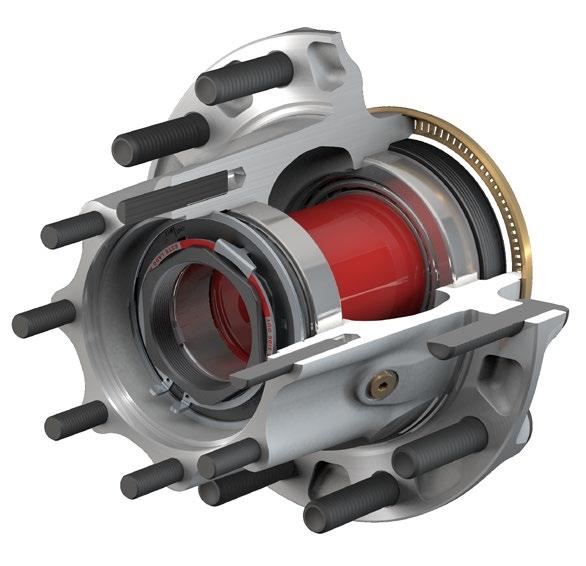
33 6. PRESET PLUS WHEEL HUBS RECOMMENDED SERVICE Recommended Service PreSet Plus Hub Assemblies PreSet Plus hub assemblies feature the same PreSet technology and include the same precision-machined hubs, premium seals and specially toleranced roller bearings. However, PreSet Plus hubs incorporate the following: 1 An integrated spindle nut that eases installation and disassembly and protects components during wheel end service An optimized spacer Standard magnetic fill plug INTEGRATED NUT OUTER BEARING CONE OUTER BEARING CUP ABS RING OIL SEAL INNER BEARING CONE INNER BEARING CUP SPACER (SECTIONED) LUBRICANT FILL PLUG a PreSet Plus Hub and Components FIGURE 60 When inspections indicate that service is necessary on a PreSet Plus Hub, follow the recommended service, inspection, reassembly and reinstallation instructions found in the following section. In order to ensure optimum wheel hub performance, recommends that only approved PreSet Plus service parts be used to replace all critical components of the system. Refer to the back of this section for a listing of approved parts. HUB REMOVAL AND DISASSEMBLY 1. Park the vehicle on a level surface. Block the wheels to prevent the vehicle from moving. 2. Raise the axle until the tires are off the floor. 3. Place safety stands under the trailer frame or under each axle spring seat (see figure 61). 2 FIGURE Remove the tire and wheel assembly using procedures specified by the wheel manufacturer (see figure 62). 3 Vehicles on jacks can fall, causing serious personal injury or property damage. Never work under a vehicle supported by a jack without supporting the vehicle with stands and blocking the wheels. Wear safe eye protection a a FIGURE If the axle is equipped with spring brake chambers, carefully compress and lock the springs so that they cannot actuate (see figure 63). 4 FIGURE For drum brakes, remove the brake drum. Support the drum during the removal process to prevent damage to the components. For disc brakes, remove caliper per manufacturers recommended procedure. 5 Sudden release of compressed air can cause serious personal injury and damage to components. Before you service a spring chamber, carefully follow the manufacturer s instructions to compress and lock the spring to completely release the brake. Verify that no air pressure remains in the service chamber before you proceed. If the hub to be disassembled is a drive hub, remove the drive axle shaft, and capture the oil (see figure 64) a a Removing the Drive Axle Shaft FIGURE 64 PreSet Plus Wheel Hubs Recommended Service PRESET PLUS WHEEL HUBS RECOMMENDED SERVICE Consolidated Metco, Inc. 29
34 PRESET PreSet PLUS Plus WHEEL Wheel HUBS Hubs RECOMMENDED Recommended SERVICE Service 6. PRESET PLUS WHEEL HUBS RECOMMENDED SERVICE 7. Place a container under the hubcap, or drive axle shaft for a drive hub, to receive the draining oil, then remove the hubcap or drive axle shaft. Do not reuse the oil. Correctly dispose of the lubricant. 8. Remove the red locking ring. Use caution not to damage the locking ring. Do not remove the spiral snap ring that holds the spindle nut in the hub. Do not loosen the axle spindle nuts by either striking them directly with a hammer, or striking a drift or chisel placed against them. Damage to the parts will occur causing possible loss of axle wheel-end components and serious personal injury. 9. Use a breaker bar to loosen the spindle nut. PreSet Plus spindle nut installation torque is 300 ft-lbs for steer hubs and 500 ft-lbs for drive and trailer hubs. 6 the hub from the spindle. If the hub will not come off of the spindle without exceeding this torque value, remove the spiral snap ring (see figure 65) and the spindle nut assembly and use a conventional hub puller to remove the hub from the spindle b Spiral Snap Ring Removal FIGURE Slide the hub off the spindle. Remove and save the outer bearing cone. Be careful when you remove the hub that you do not damage the outer bearing by dropping it on the floor. 7 FIGURE Place the hub on its outboard end and remove the seal. Retain the seal if it needs to be returned for warranty consideration. 13. Remove the inner bearing cone and spacer (see figure 67). 8 INNER BEARING CONE SPACER c a Hub Disassembly FIGURE 67 Use only 6-point forged sockets for installation and removal of PreSet Plus spindle nuts. Socket Sizes for PreSet Plus Spindle Nuts Socket Size (6 Point) FF FF Flat Keyway FL 2" 2" 2.75" If the hub is difficult to remove because the seal is stuck on the spindle, use a mechanical puller to remove the hub (see figure 66). If part of the seal remains on the spindle, carefully remove the part of the seal that remains on the spindle. Socket Size (6 Point) R TN TP 3.75" 3.125" 4" This can be done by striking the remaining portion of the seal with the round end of a ball-peen hammer. Use caution not to damage the seal journal on the spindle. 10. After the spindle nut is initially loosened with a breaker bar, loosen the spindle nut to remove the hub from the spindle. The internal snap ring will act as a hub puller and will aid in removal of the hub from the spindle. Do not exceed 50 ft-lbs of torque when removing 30 Consolidated Metco, Inc.
35 6. PRESET PLUS WHEEL HUBS RECOMMENDED SERVICE COMPONENT INSPECTION AND REPLACEMENT HAZARD ALERT MESSAGES Read and observe all hazard alert messages in this publication. They provide information that can help prevent serious personal injury, damage to components, or both. To prevent serious eye injury, always wear safe eye protection when you perform vehicle maintenance or service. Observe all warnings and cautions provided by the press manufacturer to avoid damage to components and serious personal injury. Do not hit steel parts with a steel hammer. Pieces of a part can break off. Serious personal injury and damage to components can result. Use a brass or synthetic mallet for assembly and disassembly procedures. Solvent cleaners can be flammable, poisonous and cause burns. Examples of solvent cleaners are carbon tetrachloride, and emulsion-type and petroleum-base cleaners. Read the manufacturer s instructions before using a solvent cleaner, then carefully follow the instructions. Also follow the procedures below. Wear safe eye protection. Wear clothing that protects your skin. Work in a well-ventilated area. Do not use gasoline or solvents that contain gasoline. Gasoline can explode. You must use hot solution tanks or alkaline solutions correctly. Read the manufacturer s instructions before using hot solution tanks and alkaline solutions. Then carefully follow the instructions. Do not use hot solution tanks or water and alkaline solutions to clean ground or polished parts. Damage to parts can result. CLEAN AND DRY COMPONENTS Worn or Damaged Components Do not repair or recondition wheel-end components. Replace damaged, worn or out-of-specification components. Do not mill or machine any components. Using repaired, reconditioned, damaged or worn components can cause wheel end failure, which can result in serious injury and property damage. Hub and Component Cleaning 1. Use a clean filtered solvent to clean the hub and all wheel end components. 2. Do NOT clean ground or polished parts in a hot solution tank or with water, steam or alkaline solutions. These solutions will cause corrosion of the parts. 3. Clean and inspect the wheel bearing cups and cones, race, spindle bearing and seal journals on the spindle and hub. Bearings should be cleaned with clean filtered solvent and dried with either compressed air or a lint-free rag. If compressed air is used, do not spin dry the bearings. The rollers may score due to lack of lubricant and rollers could come off which can result in serious injury. Ensure that the air line is moisture free. 4. Clean and inspect the spindle. Be sure to clean the full length of the seal journal on the spindle. 5. Parts must be dried immediately after cleaning. Dry parts with clean paper towels or rags, or compressed air. Do not dry bearings by spinning with compressed air. 6. Apply a light oil to cleaned and dried parts that are not damaged and are to be immediately assembled. Use only the type of oil used by the manufacturer. Do NOT apply oil to the brake linings or the brake drums. 7. If the parts are to be stored, apply a good corrosion preventative to all surfaces. Do NOT apply the material to the brake linings or the brake drums. Store the parts inside special paper or other material that prevents corrosion. INSPECTING BEARING CUPS AND CONES AND BEARING SPACER PreSet and PreSet Plus hubs use a precision-machined spacer in conjunction with specially toleranced bearings to control wheel end play. recommends installing a new PreSet/ PreSet Plus service kit when inspection indicates that component replacement is necessary. PreSet/PreSet Plus service kits are available from a parts dealer or distributor. If you choose to reuse existing bearings at this service, they must be inspected in accordance with the bearing manufacturers recommended guidelines. If this inspection indicates that existing bearing component(s) must be replaced, bearing cups and cones must be replaced as a set. Whenever new bearings are installed, replacement of the bearing spacer is also recommended. PreSet Plus Wheel Hubs Recommended Service PRESET PLUS WHEEL HUBS RECOMMENDED SERVICE Consolidated Metco, Inc. 31
36 PRESET PreSet PLUS Plus WHEEL Wheel HUBS Hubs RECOMMENDED Recommended SERVICE Service 6. PRESET PLUS WHEEL HUBS RECOMMENDED SERVICE 1. After components have been properly cleaned, visually inspect the cups, cones and spacer for any wear or damage. Reference materials for proper bearing inspection procedures are available from the bearing manufacturers. 9 Bearing spacers should be visually inspected for signs of wear or damage. Carefully inspect the machined ends of the bearing spacer. Wear to the bearing spacer can appear as a sharp ring of standing metal at either edge of the machined surfaces (see figure 68). Replace the spacer if it has visible wear evidenced by a raised edge on the machined end. NEW WORN SHARP EDGE Bearing Spacer Wear FIGURE If removal or replacement is required, follow the steps outlined below. REMOVING CUPS IN ALUMINUM HUBS a 1. If the bearing cup must be removed from an aluminum hub, remove it by welding a large bead around the bearing surface of the steel cup, letting the assembly cool, and removing the bearing cup (see figure 69). 10 If a welder is not available, heat the hub in an oven to a temperature not to exceed 300 F and pound out the bearing cups with a hammer and mild steel bar, being careful not to damage the hub a Welding Bead FIGURE Inspect the bearing cup bore for evidence of cup rotation or spun cups. If cup rotation exists, replace the hub. REMOVING CUPS IN IRON HUBS 1. On an iron hub, remove the bearing cup using a large hammer and a mild steel bar or a hydraulic press. Take precaution to avoid damaging the bearing cup bore and shoulder. 2. Inspect the bearing cup bore for evidence of cup rotation or spun cups. If cup rotation exists, replace the hub. INSTALLING A NEW CUP IN ALUMINUM HUBS To install a new cup in an aluminum hub, it is recommended that the hub be heated in boiling water (212 F) or in an oven at a temperature not to exceed 300 F. Cooling the cup in a freezer to 32 F or below will further ease the installation. Remove the aluminum hub from the oven or water and carefully drop in the new bearing cup being certain it is fully seated. If the cup is loose, allow a few seconds for it to heat up and secure itself before moving the hub. Use a to feeler gauge to ensure the cup is fully seated against the shoulder of the bearing bore. INSTALLING A NEW CUP IN IRON HUBS Iron hubs do not need to be heated for bearing cup installation. Press the bearing cup into the hub, being certain that it is fully seated (see figure 70). Use a to feeler gauge to ensure the cup is fully seated against the shoulder of the bearing bore. 11 Do not overheat the hub as it may degrade the heat-treated strength of the hub. Do not heat the hub with a torch or open flame. Bearing Cup Pressed into Hub FIGURE 70 WHEEL STUDS a Replace all wheel studs that have damaged or distorted threads, are broken or bent, or are badly corroded. Also, replace both studs adjacent to the damaged stud. If two or more studs have damage, replace all the studs in the hub. Broken studs are usually an indication of excessive or inadequate wheel nut torque. 32 Consolidated Metco, Inc.
37 6. PRESET PLUS WHEEL HUBS RECOMMENDED SERVICE STUD REMOVAL Observe all warnings and cautions for press operation provided by the press manufacturer to avoid serious personal injury and damage to components. 1. Place the clean hub in a shop press with the hub supported evenly around and adjacent to the stud being removed. Failure to adequately support the hub can result in physical injury and/or damage to the hub. Some hubs are configured so it is impractical to have supports to prevent the hub from tipping when force is applied to the stud. In this case, support the hub on wood blocks on the floor and use a heavy hammer to drive the studs out with several sharp blows. Be careful to avoid damaging the hub and components, particularly the seal bore and the ABS tone ring. 2. Press the stud out of the hub. STUD REPLACEMENT On the ball seat wheel mounting system, always use left-handed threaded studs, which are gold in color and have an L stamped on the end, in the hub on the driver s side of the equipment, and use right-handed threaded studs, which are silver in color and have an R stamped on the end, in the hub on the passenger s side of the equipment. The part number is located on the head of the stud. The same part number must be used for replacement unless changing the drum or wheel type. 1. To install a new stud, support the hub evenly around and adjacent to the stud being installed. 2. Press the new stud all the way into the hub. Be sure the stud is fully seated and that the stud head is not embedded into the hub. Excessive force can cause the stud head to be embedded into the hub, which can create a crack in the hub, resulting in serious injury and property damage. If a stud head is Embedded in a hub, replace the hub. HUB, DRUM AND WHEEL INSPECTION 1. Inspect the drum pilots, wheel pilots, and mounting face on the hub for damage. A damaged drum pilot is usually caused by improper drum mounting. A damaged wheel pilot could be the result of inadequate wheel nut torque, allowing the wheels to slip in service. Also, inspect other surfaces of the hub for signs of cracks or damage. 2. Inspect the wheels and brake drum for damage. Do not repair or recondition wheel-end components. Replace damaged, worn or out-of-specification components. Do not mill or machine any components. Using repaired, reconditioned, damaged or worn components can cause wheel end failure, which can result in serious injury and property damage. ABS TONE RING INSPECTION (AS APPLICABLE) The Anti-Lock Braking System (ABS) signals acts like any signal generator where the magnet passes a coil and generates a current. On hubs, the toothed ring passes a sensor and generates a signal that is sent to the ABS computer. There are three types of ABS rings used on hubs machined, stamped steel and bolt on (see figure 71). 12 FIGURE 71 If the tone ring is damaged (for example, if it is dropped, bent, chipped or dinged), it must be replaced. For a list of replacement ABS rings, refer to the Service Parts List in the back of this section. REMOVAL AND INSTALLATION OF MACHINED ABS TONE RING For a machined metal ring, remove using a chisel, making sure not to damage the hub (see figure 72). Reinstall by heating the ring to 350 F in an oven and installing it on the hub. 13 MACHINED ABS RING BOLT ON ABS RING STAMPED STEEL ABS RING b a Machined ABS Ring FIGURE 72 PreSet Plus Wheel Hubs Recommended Service PRESET PLUS WHEEL HUBS RECOMMENDED SERVICE Consolidated Metco, Inc. 33
38 PRESET PreSet PLUS Plus WHEEL Wheel HUBS Hubs RECOMMENDED Recommended SERVICE Service 6. PRESET PLUS WHEEL HUBS RECOMMENDED SERVICE REMOVAL AND INSTALLATION OF STAMPED STEEL ABS TONE RING 1. The steer axle tone ring can be removed by gripping the ring with a pair of locking pliers and tapping the pliers upward with a rubber mallet. Work around the ring to keep the ring from cocking (see figure 73). Drive axle and trailer tone rings can be removed by gripping the ring with a pair of locking pliers and prying against the head of a wheel stud to lift the ring off the hub. Work around the ring to prevent cocking (see figure 74) a Stamped Steel ABS Ring FIGURE a Stamped Steel ABS Ring FIGURE Thoroughly clean and degrease the ABS ring seat on the hub with a nonflammable solvent. 3. Place the hub in a press and place the ABS ring on the hub ring seat. 4. Using ring installation tool (part number ), center the tool over the ABS ring. Each type of ring fits a corresponding diameter on the tool (see figure 75). 16 Installing the ABS Tone Ring FIGURE Press the ring on the hub. If a press is not available, drive the ring on with a hammer or mallet until the ring seats on the hub (see figure 76). A swift initial blow with an 8-lb. hammer may be necessary to start the ring onto the hub. 17 For steer hubs, be certain the inside diameter flange is facing up a 6. Inspect the ring to ensure proper seating. If the ring is not completely seated, continue to drive the ring with the ring installation tool until it is completely seated. REMOVAL AND INSTALLATION OF BOLT ON ABS TONE RINGS (For Disc Brakes) 1. Remove and discard the fasteners holding the ABS tone ring on the hub. 2. Thoroughly clean and degrease the ABS ring seat on the hub with a non-flammable solvent. 3. Install the new ABS ring using the new fasteners included with the ring. Torque the fasteners to the torque specifications below. Thread Size Torque # in-lbs 1/4" in-lbs Replace the hub if the ABS ring seat is damaged. The ABS ring must be fully seated with a maximum of axial runout to ensure the ABS system functions properly a Using a Hammer to Install the Ring FIGURE Consolidated Metco, Inc.
39 6. PRESET PLUS WHEEL HUBS REASSEMBLY Reassembly PreSet Plus WHEEL HUBS 1. Place the hub, seal end up, on a clean work bench surface. 2. For steer hubs, install the tubular bearing spacer with the tapered end down (see figure 77). 18 Bearing Cone Assembly FIGURE Lubricate the inner bearing cone with the same lubricant as will be used in the hub and install it into the inner bearing cup (see figure 78). 19 When using an oil bath system, do not pack the bearing with grease. Grease will prevent the proper circulation of axle lubricant and can cause premature wheel seal and bearing failure. If you are working on a drive or trailer hub, go to step 3. If you are working on a steer hub, proceed as follows a The seal must be replaced every time the hub is removed from the spindle. Do not apply any gasket sealant to the seal outer or inner diameter. Always use the seal installation tool specified by the seal manufacturer. Using an improper tool can distort or damage the seal and cause premature seal failure. 4. Position the seal into the hub bore. Use a seal installation tool or flat plate and a small mallet to install the seal. seals require the proper tool for installation. Refer to the table below for a seal installation tool or flat plate dimensions. For other seals, refer to the specific manufacturers instructions. Seal Installation Tools Axle Type Flat Plate Dimensions Part Number FF Steer FL Steer R-Drive TN Trailer TP Trailer Application Seal Part Number Min. Dia. Max. Dia. FF Steer " 4.65" FL Steer " 5.4" R-Drive " 5.85" TN-Trailer " 5.85" TP-Trailer " 5.85" 20 FIGURE Check to be certain the seal is not cocked and that the seal inner diameter and the inner bearing turn freely. 7. Lubricate the inner diameter of the seal with a light film of the same lubricant as will be used in the hub. 8. Turn the hub over, and place it seal end down. For all drive and trailer hubs, install a bearing spacer. If the spacer has a tapered end, it should face towards the outboard end of the hub (see figure 80). 21 CONMET SEAL c Failure to lubricate the inner diameter of the seal may result in premature seal failure. PreSet Plus Wheel Hubs Reassembly PRESET PLUS WHEEL HUBS REASSEMBLY a Bearing Cone Assembly FIGURE When installing the seal, tap the adapter plate of the installation tool around the outer edge to position the seal. Drive the wheel seal into place (see figure 79). Once the tool bottoms out, the seal is installed correctly a Installing the Spacer FIGURE Lubricate the outer bearing cone with the same lubricant as will be used in the hub and install it into the hub assembly (see figure 81). Consolidated Metco, Inc. 35
40 PRESET PreSet PLUS Plus WHEEL Wheel HUBS Hubs REASSEMBLY Reassembly PRESET PLUS WHEEL HUBS REASSEMBLY Installing the Outer Bearing Cone FIGURE 81 Spindle Nut and Spiral Snap Ring Reassembly 1. Seat the flat washer into the back of the spindle nut (see figure 82) a 3. Install the spiral snap ring into the snap ring groove in the hub. Make sure that the snap ring is fully seated into the groove in the hub (see figures 84 and 85) b Installing Spiral Snap Ring FIGURE 84 Seating Flat Washer into Spindle Nut FIGURE Position the spindle nut and washer against the outer bearing (see figure 83) b b Fully Seating Spiral Snap Ring in Groove of Hub FIGURE b Positioning Nut and Washer Against Bearing FIGURE Consolidated Metco, Inc.
41 6. PRESET PLUS WHEEL HUBS REINSTALLATION Reinstallation INSTALLING THE PreSet Plus WHEEL HUB ASSEMBLY Failure to fill the hub with the correct amount of lubricant can cause premature failure of the PreSet Plus hub assembly, which, if not avoided, could result in death or serious injury. Use the proper hubcap for the type of lubricant intended to be used. 1. Clean the spindle to remove any lubricant, corrosion prevention coating, foreign material, or surface rust that may be present. 2. Lubricate the bearing journals on the spindle, or the inside diameter of the bearing cones with Grade 2 grease or the lubricant that will be used in the wheel end. Do not coat the seal journal on the spindle. 3. Lubricate the inside diameter of the seal with the same lubricant that will be used in the wheel end. 4. If present, remove the red locking snap ring from the spindle nut. Verify that the bearing spacer is in proper alignment. Align the key or flat on the washer with the keyway or flat on the spindle as the hub is placed onto the spindle. Use a smooth firm motion and place the hub onto the spindle. When the threads on the nut engage the threads on the spindle, rotate the nut in a clockwise direction to fully engage the threads. Steer Hub Torque the spindle nut to 300 ft-lbs while rotating the hub. DO NOT BACK OFF THE SPINDLE NUT. Drive Hub or Trailer Hub Torque the spindle nut to 500 ft-lbs while rotating the hub. DO NOT BACK OFF THE SPINDLE NUT. Socket Sizes for PreSet Plus Spindle Nuts Socket Size (6 Point) Socket Size (6 Point) FF FF Flat Keyway FL 2" 2" 2.75" R TN TP 3.75" 3.125" 4" 6. Visually examine the three holes in the face of the spindle nut. One of the holes will line up with the holes in the inner washer. Install the tab of the red locking snap ring through the hole in the nut and washer that are aligned. Spread the locking ring, push it over the spindle nut and in to the machined grooves in the spindle nut. Use caution not to bend the locking ring permanently. If the locking ring is damaged or bent, replace it with a new one. 7. Install the hub cap or drive axle with a new gasket. Torque the hub cap bolts in a star pattern to 12 to 18 ft-lbs. Torque the drive axle bolts or nuts per the drive axle manufacturer s recommendation. PreSet Plus Wheel Hubs Reinstallation PRESET PLUS WHEEL HUBS REINSTALLATION 5. Torque the spindle nut to the following torque values: Consolidated Metco, Inc. 37
42 PRESET PreSet PLUS Plus WHEEL Wheel HUBS Hubs SERVICE Service PARTS Parts Service Parts Axle Designations 6. PRESET PLUS WHEEL HUBS SERVICE PARTS Designation Typical Axle Rating (lbs) Comments Steer Axle FC Steer 8,000 Medium duty FF Steer 12,000-14,700 Standard linehaul axle. Comes in two spindle variations. 1. Flat locking feature with 12 threads/inch. 2. Keyway locking feature with 18 threads/inch. FL Steer 20,000 Vocational applications Drive Axle L-Drive 19,000 Medium duty R-Drive 20,000-23,000 Standard linehaul axle Trailer Axle TN Trailer 22,500 Tapered spindle TP Trailer 25,000 Parallel spindle or "Propar" NOTE: These axle ratings are to be used as a reference only. Refer to the vehicle's door plate for your specific application. PreSet Plus Service Kits and Components PreSet Plus Hubs Rebuild Kit Seal and Spacer Kit Magnetic Fill Plug Nut Assembly Kit* Red Locking Snap Ring* FF Flat N/A FF Keyway N/A FL N/A R-Drive TN TP Rebuild kit includes seal, bearing spacer, inner cup and cone, outer cup and cone. Seal and spacer kit includes seal and bearing spacer. Nut assembly kit includes integrated spindle nut, locking washer, red locking snap ring and spiral nut retaining ring. *Not available for PreSet hub assemblies. Seals Position Spindle Type Aftermarket Part Number Steer FF Spindle FL Spindle Drive R Spindle Trailer TP Spindle TN Spindle Consolidated Metco, Inc.
43 6. PRESET PLUS WHEEL HUBS SERVICE PARTS Seal Installation Tools Axle Designation Installation Tool Part Number Min. Dia.* Max. Dia.* FF Steer " 4.65" FL Steer " 5.4" R-Drive TN Trailer TP Trailer " 5.85" *Required flat plate dimensions if you are not using a installation tool (minimum of 3/8", 9.5 mm thick). Approved PreSet Plus Aftermarket Bearings Description Number Bearing Set Number FC Steer Axle Inner Cup & Cone Outer Cup & Cone Not available in sets FF Steer Axle Inner Cup & Cone Set 427 Outer Cup & Cone Set 428 FL Steer Axle Inner Cup & Cone Set 445 Outer Cup & Cone Set 446 L-Drive Axle Inner Cup & Cone Outer Cup & Cone Not available in sets R-Drive Axle Inner Cup & Cone Set 429 Outer Cup & Cone Set 430 TN Trailer Axle Inner Cup & Cone Set 431 Outer Cup & Cone Set 427 TP Trailer Axle Inner Cup & Cone Set 432 Outer Cup & Cone Set 432 PreSet Plus Wheel Hubs Service Parts PRESET PLUS WHEEL HUBS SERVICE PARTS Consolidated Metco, Inc. 39
44 PRESET PreSet PLUS Plus WHEEL Wheel HUBS Hubs SERVICE Service PARTS Parts 6. PRESET PLUS WHEEL HUBS SERVICE PARTS ABS Rings for Hubs (for reference only) Axle Material Type of Brake Hub Casting Number ABS Ring Part Number FC Steer Iron Drum FF Steer Aluminum Disc Drum Iron Disc Drum FL Aluminum Drum Iron Disc L-Drive (190) Iron Disc Drum R-Drive Aluminum Disc Drum Iron Drum TN Aluminum Drum TP Aluminum Disc Drum Iron Drum If an ABS ring is not listed for a particular hub, contact Customer Service at Approved Trailer Hub Caps Axle Designation Type of Lubricant PreSet Plus Hub Cap Part Number TN Trailer Semi-Fluid Grease TP Trailer Semi-Fluid Grease TN Trailer Oil TP Trailer Oil Consolidated Metco, Inc.
45 7. LUBRICATION Lubrication DRIVE HUB LUBRICATION Drive hubs can be lubricated by installing one quart of oil through the fill plug in the barrel of the hub. The proper installation torque for the fill plug is ft-lbs. If no fill plug is present, the drive hub can be lubricated by lifting the opposite side of the axle 8" to allow the lubricant to run down the axle housing and into the hub assembly. Elevate the axle for two minutes to allow the lubricant time to fill the hub. Repeat the process for the opposite side of the vehicle. The rear axle carrier should be filled to the proper level to ensure adequate lubricant is available to fill the entire hub. Refill the carrier to the proper level after this procedure is completed. STEER AND TRAILER HUBS WITH OIL LUBRICANT Only use oil approved by the seal manufacturer (see approved list from the seal manufacturer or on Some hubs are provided with a fill hole, located in the barrel and between the bearings for adding lubricant. 1. Fill the hub through the hubcap or the fill hole with oil. It may be necessary to add lubricant more than once to adequately fill the hub (see figure 86). 27 Filling the Hub with Oil FIGURE Be certain the hubcap is properly filled to the oil level mark on the face of the cap (see figure 87). Allow the initial fill amount to settle for 10 minutes. Repeat the fill procedure until the oil is at the fill line on the hubcap. 28 FULL LINE Fill to Oil Level Line FIGURE Be sure to put the fill hole plug back into the hubcap and that the vent is working properly. TRAILER HUBS WITH SEMI-FLUID GREASE LUBRICANT 1. Remove the fill hole plug a a Failure to fill and maintain the hub with the correct amount of semi-fluid grease may cause premature failure of the wheel hub system, bearing failure and possible loss of the wheel. 2. Loosen the hubcap bolts to allow air to escape while the hub is filling. 3. Fill the hub with the OEM recommended amount of room temperature (60 F minimum) semi-fluid grease through the fill hole in the hub (see figure 88). 29 For proper fill levels using semi-fluid grease, see the chart on the next page a Filling Hub with Semi-Fluid Grease FIGURE Retorque the hubcap bolts to ft-lbs in a star pattern. 5. Reinstall and tighten the fill plug to ft-lbs. Consolidated Metco, Inc. 41
46 7. LUBRICATION (CONTINUED) Recommended Fill Volumes for Semi-Fluid Grease HUB TYPE MATERIAL BRAKE TYPE PreSet NO. NO. OF OF STUDS CASTING NUMBERS* VOLUME** VOLUME** Non PreSet (FL.OZ.) VOLUME HUB TN TYPE MATERIAL Aluminum BRAKE Drum TYPE STUDS 10 NUMBERS* (FL.OZ.) (FL.OZ.) 23 TN Aluminum Drum TN Aluminum Drum Drum TN Aluminum Drum Aluminum TN Aluminum Disc TN Iron Drum Disc TN Aluminum Disc TN TN Iron Drum TN Iron Drum TN Iron Drum Drum TP Aluminum Iron Drum TP Aluminum Drum TP Aluminum Drum TP Iron Drum Disc TP Iron Disc TP Aluminum Disc TP Aluminum Drum Disc TP Aluminum Iron Drum TP Aluminum Drum TP Iron Drum Disc *Hub casting numbers can be found cast onto the flange 10of the hub For part numbers 46.9 that don t appear 46.9 in the chart, TP contact customer service at or go to conmet.com **These fill volumes were established with hubcaps and are to be used as reference only Drum Iron Disc *Hub casting numbers can be found cast onto the flange of the hub. For part numbers that don t appear in the chart, contact customer service at or go to conmet.com. **These fill volumes were established with hubcaps and are to be used as reference only. 42 Consolidated Metco, Inc.
47 8. BRAKE AND WHEEL INSTALLATION Brake and Wheel Installation Caliper Installation Reinstall and adjust the brake pads and brake caliper according to the brake manufacturer s recommended instructions. Wheel Installation 1. Reinstall the wheels and torque the wheel bolts in a star pattern to ft-lbs. The last nut rotation must be with a torque-controlled device. 2. After the first 50 to 100 miles, retorque the wheel nuts to ft-lbs in a star pattern. The last nut rotation must be with a torque-controlled device. 30 Hub Pilot Wheel Mounting System The brake drum must be fully seated on the drum pilot and against the hub face during and after installation of the wheel(s). If your shop practice requires the use of lubricant or anticorrosion material to the threads and/or the drum pilot area, avoid getting lubricant on the flat mating surfaces of the hub, drum, and wheels. Always snug the top nut first to fully seat the brake drum on the drum pilot and against the hub face. See the adjacent diagram for bolt tightening sequence, and tighten in order from 1 through 8 or 10, depending on the bolt pattern (see figure 89 and figure 90) Stud Tightening Sequence FIGURE a a 8 Stud Tightening Sequence FIGURE Clean all mating surfaces on the hub, drum and nuts. Remove loose paint, scale, and any material building around the pilots of the drum, hub, and wheels. Be sure paint is fully cured on recently refurbished wheels. Care should be taken to avoid damaging the hub or other components. 33 If you plan to replace the brake drum (i.e., cast in place of CentriFuse ) or wheels (i.e., aluminum in place of steel), measure stud standout (see figure 91). In hub piloted mounting systems, the studs must be long enough for the threads to be exposed beyond the installed wheel nut. In the ball seat mounting system, the stud length beyond the brake drum should be from ʺ as measured from the brake drum to the end of the stud. Call at for the correct stud part number for your application. If you plan to replace the brake drum, verify the new drum has the same drum pilot diameter as the one that has been removed. BRAKE DRUM HUB a Measuring Stud Standout FIGURE In environments where a corrosion inhibitor is beneficial, recommends the use of Corrosion Block, a product of Lear Chemical Research, (905) In severely corrosive environments, a light coat of Corrosion Block on the drum and wheel pilots has proven beneficial. 3. In addition to the above preparation, apply two drops of oil to a point between the nuts and nut flange washer and two drops to the last two or three threads at the end of each stud. Also, lightly lubricate the pilots on the hub to ease wheel installation and removal. Consolidated Metco, Inc. 43
48 8. BRAKE AND WHEEL INSTALLATION (CONTINUED) 4. Before installation of brake drums and wheels that utilize the hub piloted system, rotate the hub so one of the wheel pilot bosses is at the top (12 o clock position) (see figure 92). 34 Rotating the Hub FIGURE Position the brake drum over the hub, so it seats on the drum pilot and against the hub face. 6. Place the wheel(s) into position. One or more nuts can be started in order to hold wheel(s) and drum into position. 7. Snug the top nut first. Apply 50 ft-lbs torque to draw the brake drum up fully against the hub (see figure 93). 35 Do not get lubricant on the mounting face of the drum or wheel. Failure to clean lubricant from these surfaces may result in decreased clamping load. WHEEL PILOT BOSS a b Reinstalling the Wheel FIGURE Install the remaining wheel nuts and using the sequence as shown, torque all the nuts to 50 ft-lbs, then retorque to ft-lbs (see figure 89 and figure 90). The last nut rotation must be with a calibrated torquing device. When torquing wheel nuts, the temperature of all the wheel end components should be as close as possible to the midpoint of the expected operating range. For example, if the hub will operate between 0 F and 150 F, 75 F is a good temperature to torque at. Room temperature is often a close approximation of the midpoint temperature. This recommendation is due to the differences in the coefficient of thermal expansion for the various materials in the wheel end including the hub, studs, wheel and brake drum. If the wheel nuts are torqued at temperatures well below the midpoint, when the system warms up, the studs may become overstressed. This could cause the studs to be permanently stretched, leading to nut loosening or damage to the wheel or hub. If the torque is applied at elevated temperatures, the system may become loose and lose clamp at lower temperatures, resulting in wheel damage and broken wheel studs. If the nuts must be torqued at extreme temperatures, the nut torque should be readjusted when the temperature is in the desired range. See also TMC RP250 "Effects of Extreme Temperatures on Wheel Torque and Clamp Load". Use the appropriate nuts with the above technique to install the front and outer dual wheels. Follow your shop practice to locate the valve stems. 9. Inspect the brake and wheel installation by checking the seating of the wheel(s) and drum at the pilots, and by turning the wheel(s) and checking for any irregularity. Ball Seat Wheel Mounting System 1. Clean all mating surfaces on the hub, drum, wheels and nuts. Remove loose paint, scale, and any material building around the pilots of the drum, hub, and wheels. Be sure paint is fully cured on recently refurbished wheels. 36 Excessive or inadequate wheel nut torque can cause a failure of the wheel mounting system and a wheel separation resulting in severe personal injury or death and property damage. Always use a device that measures the torque being applied. After the first miles, retorque all the nuts to ft-lbs. Loosen the outer nuts to retorque the inner nuts. When dual wheels are mounted, the stud length beyond the brake drum (standout) should be from as measured from the brake drum to the end of the stud (see figure 94). When mounting dual aluminum wheels, use ALCOA inner cap nuts 5978R and 5978L or the equivalent. These nuts can also be used with longer studs up to 1.88 standout. For special single aluminum wheel applications on drive and trailer hubs, use ALCOA single cap nuts 5995R and 5995L, or 5554R and 5554L or the equivalent, depending on the stud thread length (see Table A). For single steel wheel applications, use BATCO R and L or the equivalent (see Table B). BRAKE DRUM HUB a Stud Standout FIGURE Consolidated Metco, Inc.
49 8. BRAKE AND WHEEL INSTALLATION (CONTINUED) Table A: Single Aluminum Wheel Applications Aluminum Wheels 3/4-16 Threaded Studs Table B: Single Steel Wheel Applications BATCO Cap Nut Steel Wheels Number 3/4-16 Threaded Studs 2. When installing the inner wheel and tire assembly, verify the inner nuts being used are suitable for the application: aluminum wheels, steel wheels, brake drum thickness, etc. 3. Rotate the hub to bring a drum pilot to the top (12 o clock) position (see figure 95). Position the inner wheel and tire assembly over the studs against the drum. 37 ALCOA Cap Nut Number 5995R and 5995L or 5554R and 5554L, depending on stud length R and L Inner cap nuts must be deep enough to ensure the stud will not bottom inside the nut and must be of a configuration approved by wheel manufacturer. DRUM PILOT a Rotating the Drum Pilot to 12 O Clock FIGURE Beginning in the 12 o clock position, install the inner cap nuts by hand to ensure they are not cross-threaded. Do not tighten any nuts at this time. 5. Apply sufficient torque (about 50 ft-lbs) to the inner top cap nut to draw the brake drum up on the drum pilot and against the hub and seat the ball seat of the nut into the ball socket of the wheel (see figure 96). 38 Tightening the Inner Cap Nuts FIGURE To properly center the wheel, snug the remaining wheel nuts. Verify the drum is in place over the drum pilots (see figure 97). 39 INNER CAP NUT AT 12 O CLOCK POSITION a a 10 Stud Tightening Sequence FIGURE Starting with the top nut first and using a staggered pattern, torque the inner wheel nuts in stages to ft-lbs (see figure 98). The last nut rotation must be with a calibrated torquing device. 40 Torquing the Inner Wheel Nuts FIGURE Install the outer wheel and nuts and tighten to ft-lbs (see figure 99). The last nut rotation must be with a calibrated torque device b Use the appropriate nuts with the above technique to install the front and outer dual wheels. Follow your shop practice to locate the valve stems b Torquing the Outer Wheel Nuts FIGURE Inspect the brake and wheel installation by checking the seating of the wheel(s) and drum at the pilots and by turning the wheel(s) and check for any irregularity. Excessive or inadequate wheel nut torque can cause a failure of the wheel mounting system and a wheel separation resulting in severe personal injury or death and property damage. Always use a device that measures the torque being applied. After the first miles, retorque all the nuts to ft-lbs. Loosen the outer nuts to retorque the inner nuts. Consolidated Metco, Inc. 45

50 9. WHEEL HUB AND ROTOR Wheel Hub and Rotor WHEEL HUBS WITH DISC BRAKE ROTORS This section applies to brake rotors designed and manufactured by for air disc brake applications. also manufactures hub assemblies equipped with brake rotors designed and manufactured by other brake companies. If your vehicle is equipped with a brake rotor other than a design, please refer to the vehicle or component manufacturer's published service information. Part Number Identification Before you perform any service procedures, you must first determine if the vehicle is equipped with a disc brake rotor designed and manufactured by. rotors can be identified by part number. The part numbers are cast into the rotor as shown in figure 100 or stamped into the rotor as shown in figure Rotor Identification a Flat Rotor FIGURE 102 Information relating to disc brake calipers, pads, or other vehicle-related systems is not included in this manual. Information regarding other brake-related components should be obtained from the vehicle or component manufacturer's published service information a Cast Rotor Part Number FIGURE a U-Shaped Rotor FIGURE a a Stamped Rotor Part Number FIGURE Hat Rotor FIGURE 104 Use this part number to find the part specific service information in section 12 of this manual a Splined Rotor *Bendix Splined Rotor Refer to Bendix for splined rotor information FIGURE Consolidated Metco, Inc.


51 10. HUB AND ROTOR INSPECTION Hub and Rotor Inspection HAZARD ALERT MESSAGES Read and observe all hazard alert messages in this publication. They provide information that can help prevent serious personal injury, damage to components, or both. To prevent serious eye injury, always wear safe eye protection when you perform vehicle maintenance or service. Do not work under a vehicle supported only by jacks. Jacks can slip and fall over. Serious personal injury and damage to components can result. Park the vehicle on a level surface. Block the wheels to prevent the vehicle from moving. Support the vehicle with safety stands. Some brake linings contain asbestos fibers, a cancer and lung disease hazard. Some brake linings contain non-asbestos fibers, whose long-term effects to health are unknown. Use caution when handling both asbestos and non-asbestos materials. DISC BRAKE ROTOR INSPECTION A disc brake component inspection should be a part of any pre-trip inspection and regularly-scheduled preventive maintenance program. Follow all shop safety procedures before beginning vehicle inspection. 1. Lift and support the axles with safety stands. Refer to the vehicle manufacturer's recommended instructions. 2. Remove the wheels from the hub. 3. Rotate the hub and visually inspect both sides of the rotor for the out of service conditions detailed in this section. If any of these conditions are found, remove the hub and replace the rotor according to the instructions in this manual. Heat Checks Heat checks are caused by the repeated heating and cooling of the braking surface. They appear as short, thin, radial interruptions in the braking surface. There may be numerous light and heavy heat checks on the braking surface. See figure 106 for examples of light heat checking and figure 107 for heavy heat checking. Cracks Heat checks may wear away or they may eventually become braking surface cracks. Rotors should be replaced if cracks become over 0.060" wide or over 0.060" deep and extend over 75% of the braking surface in the radial direction a Light Heat Check FIGURE Heavy Heat Check FIGURE 107 Cracked rotors may be caused by mishandling, brake balance issues, wear beyond the minimum allowable thickness, or driver abuse. If a crack extends through a section of the rotor, the rotor should be replaced. If a crack is found on the mounting section of the rotor, the rotor should be replaced. Figure 108 shows a cracked rotor that should be replaced. The crack in figure 109 is acceptable to run, but the rotor should be inspected on a regular basis to ensure that the crack has not progressed a a Unacceptable Crack FIGURE 108 Consolidated Metco, Inc. 47


.")

52 10. HUB AND ROTOR INSPECTION (CONTINUED) 51 Acceptable Crack FIGURE 109 Deep Grooves or Scoring Grooves or scoring may be caused by contaminants trapped between the lining and the rotors, worn out linings, or the lining plate contacting the rotor. Grooves or scoring on the brake rotor are acceptable if they are less than 0.060" deep. If the rotor thickness, when measured across a groove, is less than the minimum allowable thickness for the rotor, the rotor should be replaced. See figure 110 for example of grooves on the braking surface of the rotor. 52 Grooves on Brake Surface FIGURE 110 Blue Marks or Bands a a If the rotor has become extremely hot, the braking surface may exhibit blue marks or bands. See figure 111 for examples of these marks. This condition may be caused by continued hard stops, improper brake balance, improper brake caliper clearance, operation, or adjustment. The cause of overheating should be determined and corrected. It is not necessary to replace the rotor as long as it meets the proper dimensional specifications for runout and thickness. 53 Polished Rotors Blue Marks FIGURE 111 A polished rotor will have a mirror-like finish on the braking surface (see figure 112). This condition may be caused by improper lining friction rating, lightly dragging brakes, or a rotor resurfaced to too fine of a microfinish. To correct this condition, sand the braking surface on the rotor and the brake pads with 80 grit emery cloth. The microfinish should be 120 to 150 RMS. If the condition returns, verify that the linings on the brake pads have the correct friction rating for the application a a Polished Rotor FIGURE 112 Martensite Spotted Rotors Rotors subjected to extremely high heat followed by rapid cooling can exhibit a Martensite Spotted condition. This condition appears as black spots on the rotor that are slightly raised and are hard and brittle (see figure 113). The high temperatures cause a structural change to the rotor material. This condition can make the rotor more susceptible to cracking. Rotors with this condition should be replaced. Check the brake linings for uneven wear and replace as necessary. After the rotor has been replaced, and the hub and rotor reinstalled onto the axle, the brake system should be checked for brake drag and proper brake balance. 55 Martensite Spotted Rotor FIGURE 113 Grease-Stained Rotors a Brake rotors that have discolorations due to grease or oil on the brake surface should be removed from the vehicle and cleaned to remove the grease or oil (see figure 114). The brake pads should be inspected and replaced if they are found to be soaked with grease or oil. The source of the grease or oil should be identified and repaired. 48 Consolidated Metco, Inc.
.")


. If the runout exceeds 0.035\", the rotor should be replaced.")
53 10. HUB AND ROTOR INSPECTION (CONTINUED) 56 Clogged or Restricted Vent Holes 59 Lining Transfer Grease-Stained Rotor FIGURE 114 High operating temperatures or improper lining material can result in brake lining transfer onto the braking surface of the brake rotor (see figure 115). This may start as a spotty thin layer of lining material that has become welded to the brake rotor and may end up covering most of the braking surface. This condition will accelerate lining wear. The buildup can be removed by resurfacing the brake rotor. Rotors should not be resurfaced to less than 0.060" above the minimum allowable thickness to allow for wear. The cause of the high brake operating temperature should be identified and corrected before the vehicle is put back into service a a Lining Transfer FIGURE 115 Off-road and severe-duty applications may result in vent holes in the rotor becoming blocked by an accumulation of debris such as rocks or dirt (see figure 116). The vent holes should be cleaned as required to allow air flow and proper cooling of the brake rotor. 58 Rotor Runout a Clogged Vent Holes FIGURE 116 Lateral runout, or wobble, on the rotor braking surface should not exceed 0.020" in one full revolution of the rotor. The measurement should be taken with a dial indicator at the center of the rotor braking surface. See figure 117 for proper runout measurement set up. The runout measurement should not include end play of the wheel bearings. If the runout measurement is over 0.020", the end play of the wheel bearings should be checked. If the wheel bearing end play is greater than the manufacturer's recommendations, the wheel bearings should be adjusted per the manufacturer's recommendations. Radial runout on the outside diameter of the braking surface should not exceed 0.035" when checked with a dial indicator (see figure 118). If the runout exceeds 0.035", the rotor should be replaced. 60 Rotor Thickness Lateral Runout FIGURE 117 Radial Runout FIGURE 118 The rotor thickness should be measured at three points using a micrometer as shown in figures 119, 120 and 121. If the rotor thickness varies more than 0.005" between any two places, the rotor should be replaced. 61 CENTER OF ROTOR BRAKING SURFACE TOP OF ROTOR a OUTSIDE DIAMETER OF ROTOR a a Top of Rotor FIGURE 119 Consolidated Metco, Inc. 49


54 10. HUB AND ROTOR INSPECTION (CONTINUED) 62 MIDDLE OF ROTOR a Middle of Rotor FIGURE BOTTOM OF ROTOR Rotor Resurfacing a Bottom of Rotor FIGURE 121 does not recommend resurfacing disc brake rotors. However, if rotor resurfacing is necessary, be sure that at least 0.060" of material is left above the rotor minimum thickness specification to allow for wear before the minimum allowable rotor thickness is reached. 50 Consolidated Metco, Inc.

55 11. HUB AND ROTOR REMOVAL AND DISC REPLACEMENT Hub and Rotor Removal and Disc Replacement HAZARD ALERT MESSAGES Read and observe all hazard alert messages in this publication. They provide information that can help prevent serious personal injury, damage to components, or both. Do not work under a vehicle supported only by jacks. Jacks can slip and fall over. Serious personal injury and damage to components can result. Park the vehicle on a level surface. Block the wheels to prevent the vehicle from moving. To prevent serious eye injury, always wear safe eye protection when you perform vehicle maintenance or service. HUB AND ROTOR REMOVAL 1. Lift the axle and support it with safety stands. Refer to the vehicle manufacturer's recommended instructions. 2. Remove the tires and wheels. 3. Remove the hubcap or drive axle. Refer to the manufacturer's recommended instructions. 4. Follow the brake manufacturer's instructions to remove the brake caliper and brake pads from the axle mounting point. Do not loosen the axle spindle nuts by either striking them directly with a hammer, or striking a drift or chisel placed against them. Damage to the parts will occur causing possible loss of axle wheel-end components and serious personal injury. 5. Remove the spindle nut assembly. Refer to Conventional, PreSet and PreSet Plus hub removal procedures in this manual for specific spindle nut removal instructions. 6. Slide the hub and rotor assembly off the spindle. Be careful not to damage the outer bearing. 7. Remove the bolts that secure the rotor to the hub. Be careful not to damage the ABS tone ring when the rotor is removed. 8. Remove the seal from the hub. 9. Clean the bearing cups and cones, bearing spacer, grease cavity, and seal bore of the hub. 10. Inspect all components for signs of wear or damage. Replace components as necessary. 11. Clean the spindle. It may be necessary to remove the inner portion of the seal from the spindle. If necessary, use emery cloth to remove rust and foreign material from the seal journal on the spindle. 12. Clean the rotor mounting area of the hub. DISC BRAKE ROTOR REPLACEMENT PART IDENTIFICATION The brake rotor can be identified by the part number that is cast or stamped into the rotor. Use the brake rotor part number to find the specific replacement instructions for the hub and rotor assembly you are working on (see figures 122 and 123) Do not hit steel parts with a steel hammer. Pieces of a part can break off. Serious personal injury and damage to components can result. Use a brass or synthetic mallet for assembly and disassembly procedures a Cast Part Number FIGURE a Stamped Part Number FIGURE 123 Consolidated Metco, Inc. 51
 Install the brake rotor using only the hardware provided in the brake rotor kit. 1. Clean the rotor mounting surface on the hub and position the disc brake rotor on to the hub. 2.")
56 12. DISC BRAKE ROTOR REPLACEMENT Disc Brake Rotor Replacement ROTOR REPLACEMENT PROCEDURES 66 Flat Rotor Service Kit Part Number Rotor Minimum Thickness 1.42" (36.1 mm) Install the brake rotor using only the hardware provided in the brake rotor kit. 1. Clean the rotor mounting surface on the hub and position the disc brake rotor on to the hub. 2. Install and torque the rotor capscrews in a star pattern to ft-lbs a Medium Duty Flat Rotor FIGURE Hub Assembly 2. Flat Rotor 3. 1/2" Flat Washer (10 ea.) 4. 1/2"-20 UNF Rotor Cap Screw (10 ea.) See Service Manual for detailed hub service information. See Section 10 for out of service conditions /2"-20 UNF rotor cap screws. Torque in a star pattern to ft-lbs. Clean all component mating surfaces before reassembly b Rotor Installation FIGURE Consolidated Metco, Inc.
 Install the brake rotor using only the hardware provided in the rotor kit. 68 1.")
57 12. DISC BRAKE ROTOR REPLACEMENT (CONTINUED) Flat Rotor Service Kit Part Number Rotor Minimum Thickness 1.46" (37 mm) Install the brake rotor using only the hardware provided in the rotor kit If the studs were removed, apply Loctite 272 to the coarse threaded end of the double- ended stud and to the rotor mounting threads in the hub. Install the studs. Clean all mating surfaces. If Loctite 272 is not available, use Loctite Clean all mating surfaces a Flat Rotor FIGURE Place the steel insulator and rotor on the hub. 4. Install and torque the rotor mounting bolts in a star pattern to ft-lbs. 5. Place the ABS tone ring on the rotor. 6. Install and torque the #8-32 UNF truss head screws in a star pattern to in-lbs Flat Rotor 2. Hub Assembly 3. #8-32 UNF Truss Head Screw, 10 Ea. 4. ABS Tone Ring 5. 5/8-18 UNF Flanged Hex Head Nut, 10 Ea. 6. Stainless Steel Insulator 5 1 See Service Manual for detailed hub service information Clean all component mating surfaces before reassembly. See Section 10 for out of service conditions. 5/8-18 UNF FLANGED HEX HEAD NUTS Torque to ft-lbs in a star pattern. #8-32 UNF truss head screw. Torque in a star pattern to in-lbs b Rotor Installation FIGURE 127 Consolidated Metco, Inc. 53

58 12. DISC BRAKE ROTOR REPLACEMENT (CONTINUED) 70 Flat Rotor Service Kit Part Number (FF Steer) Rotor Minimum Thickness 1.46" (37 mm) a Flat Rotor FIGURE If the rotor mounting studs were removed from the hub during disassembly, apply Loctite 272 to the coarse end of the double-ended stud and to the rotor mounting threads in the hub. Install the studs. 2. Clean all mating surfaces. 3. Place the steel insulator and the rotor on the hub. 4. Install and torque the rotor mounting nuts in a star pattern to ft-lbs. 5. Place the ABS ring on the rotor. 6. Install and torque the #8-32 UNF truss head screws in a star pattern to in-lbs. Install the brake rotor using only the hardware provided in the brake rotor kit. If Loctite 272 is not available, use Loctite Flat Rotor 2. Hub Assembly 3. #8-32 UNF Truss Head Screw 4. ABS Tone Ring 5. 5/8"-18 UNF Flanged Hex Head Nut (10 ea.) 6. Stainless Steel Insulator 2 See Service Manual for detailed hub service information Clean all component mating surfaces before assembly. See Section 10 for out of service conditions. 5/8-18 UNF flanged hex head nuts. Torque to ft-lbs in a star pattern. #8-32 UNF truss head screw threads. Torque in a star pattern to in-lbs b Rotor Installation FIGURE Consolidated Metco, Inc.
59 12. DISC BRAKE ROTOR REPLACEMENT (CONTINUED) 434 mm Flat Rotor FF Service Kit Part Number (FF Steer) Rotor Minimum Thickness 1.46" (37 mm) Install the brake rotor using only the hardware provided in the brake rotor kit If the rotor mounting studs were removed from the hub during disassembly, apply Loctite 272 to the coarse end of the double-ended stud and to the rotor mounting threads in the hub. Install the studs. If Loctite 272 is not available, use Loctite Clean all mating surfaces. 3. Place the steel insulator and the rotor on the hub a Flat Rotor FIGURE Install and torque the rotor mounting nuts in a star pattern to ft-lbs. 5. Press the ABS ring onto the hub Flat Rotor 2. Hub Assembly 3. ABS Tone Ring 4. 5/8"-18 UNF Flanged Hex Head Nut (10 ea.) 5. Stainless Steel Insulator See Service Manual for detailed hub service information Clean all component mating surfaces before assembly. See Section 10 for out of service conditions. 5/8-18 UNF flanged hex head nuts. Torque to ft-lbs in a star pattern a Rotor Installation FIGURE 131 Consolidated Metco, Inc. 55
 Install the brake rotor using only the hardware provided in the brake rotor kit. 74 1.")
60 12. DISC BRAKE ROTOR REPLACEMENT (CONTINUED) 434 mm Flat Rotor R-Drive Service Kit Part Number (R Drive) Rotor Minimum Thickness 1.46" (37 mm) Install the brake rotor using only the hardware provided in the brake rotor kit If the rotor mounting studs were removed from the hub during disassembly, apply Loctite 272 to the coarse end of the double-ended stud and to the rotor mounting threads in the hub. Install the studs. If Loctite 272 is not available, use Loctite Clean all mating surfaces. 3. Place the steel insulator and the rotor on the hub a Flat Rotor FIGURE Install and torque the rotor mounting nuts in a star pattern to ft-lbs. 5. Place the ABS ring on the rotor. 6. Install and torque the 1/4-20 UNF hex head screws in a star pattern to in-lbs Flat Rotor 2. Hub Assembly 3. ABS Tone Ring 4. 5/8"-18 UNF Flanged Hex Head Nut (10 ea.) 5. Stainless Steel Insulator 6. 1/4-20 UNF Hex Cap Screws See Service Manual for detailed hub service information See Section 10 for out of service conditions. 5/8-18 UNF flanged hex head nuts. Torque to ft-lbs in a star pattern. 1/4-20 UNF hex head screws. Torque in a star pattern to in-lbs. Clean all component mating surfaces before assembly a Rotor Installation FIGURE Consolidated Metco, Inc.
61 12. DISC BRAKE ROTOR REPLACEMENT (CONTINUED) 410 mm Flat Rotor FF Service Kit Part Number (FF Steer) Rotor Minimum Thickness 1.46" (37 mm) Install the brake rotor using only the hardware provided in the brake rotor kit If the rotor mounting studs were removed from the hub during disassembly, apply Loctite 272 to the coarse end of the double-ended stud and to the rotor mounting threads in the hub. Install the studs. If Loctite 272 is not available, use Loctite Clean all mating surfaces. 3. Place the steel insulator and the rotor on the hub a Flat Rotor FIGURE Install and torque the rotor mounting nuts in a star pattern to ft-lbs. 5. Place the ABS ring on the hub Flat Rotor 2. Hub Assembly 3. ABS Tone Ring 4. 5/8"-18 UNF Flanged Hex Head Nut (10 ea.) 5. Stainless Steel Insulator See Service Manual for detailed hub service information Clean all component mating surfaces before assembly. See Section 10 for out of service conditions. 5/8-18 UNF flanged hex head nuts. Torque to ft-lbs in a star pattern a Rotor Installation FIGURE 135 Consolidated Metco, Inc. 57
 Install the brake rotor using only the hardware provided in the brake rotor kit. 78 1.")
62 12. DISC BRAKE ROTOR REPLACEMENT (CONTINUED) 410 mm Flat Rotor R-Drive Service Kit Part Number (R Drive) Rotor Minimum Thickness 1.46" (37 mm) Install the brake rotor using only the hardware provided in the brake rotor kit If the rotor mounting studs were removed from the hub during disassembly, apply Loctite 272 to the coarse end of the double-ended stud and to the rotor mounting threads in the hub. Install the studs. If Loctite 272 is not available, use Loctite Clean all mating surfaces. 3. Place the steel insulator and the rotor on the hub a Flat Rotor FIGURE Install and torque the rotor mounting nuts in a star pattern to ft-lbs. 5. Place the ABS ring on the rotor. 6. Install and torque the 1/4-20 UNF hex head screws in a star pattern to in-lbs. 1. Flat Rotor 2. Hub Assembly 3. ABS Tone Ring 4. 5/8"-18 UNF Flanged Hex Head Nut (10 ea.) 5. Stainless Steel Insulator 6. 1/4-20 UNF Hex Cap Screws See Service Manual for detailed hub service information See Section 10 for out of service conditions. 5/8-18 UNF flanged hex head nuts. Torque to ft-lbs in a star pattern. 1/4-20 UNF hex head screws. Torque in a star pattern to in-lbs. Clean all component mating surfaces before assembly a Rotor Installation FIGURE Consolidated Metco, Inc.
 Install the brake rotor using only the hardware provided in the rotor kit. 80 1. Clean the rotor mounting surface on the hub and position the disc brake rotor onto the hub. 2.")

63 12. DISC BRAKE ROTOR REPLACEMENT (CONTINUED) Hat-Shaped Rotor Service Kit Part Number Rotor Minimum Thickness 1.32" (33.5 mm) Install the brake rotor using only the hardware provided in the rotor kit Clean the rotor mounting surface on the hub and position the disc brake rotor onto the hub. 2. Install and torque the rotor capscrews in a star pattern to ft-lbs a Hat-Shaped Rotor FIGURE Hat-Shaped Rotor 2. Hub Assembly 3. 9/16"-12 UNC Rotor Capscrew, 10 Ea. 4. 9/16" Flat Washer, 10 Ea. See Service Manual for detailed hub service information Clean all component mating surfaces before reassembly. 9/16"-12 UNC rotor capscrew. Torque in a star pattern to ft-lbs. See Section 10 for out of service conditions b Rotor Installation FIGURE 139 Consolidated Metco, Inc. 59
 Install the brake rotor using only the hardware provided in the brake rotor kit. 82 1. Clean the mounting surfaces on the hub and place the disc brake rotor onto the hub.")
64 12. DISC BRAKE ROTOR REPLACEMENT (CONTINUED) U-Shaped Rotor Service Kit Part Number Rotor Minimum Thickness 1.46" (37.0 mm) Install the brake rotor using only the hardware provided in the brake rotor kit Clean the mounting surfaces on the hub and place the disc brake rotor onto the hub. Install the disc brake rotor using the hardware provided in the brake rotor kit. 2. Install and torque the rotor capscrews in a star pattern to ft-lbs a Hat-Shaped Rotor FIGURE U-Shaped Rotor 2 2. Hub Assembly 3. M16X1.5 MM Hex Head Capscrews with Flat Washers, 10 Ea. See Service Manual for detailed hub service information. 1 3 Torque in a star pattern to ft-lbs. Clean all component mating surfaces before reassembly. See Section 10 for out of service conditions b Rotor Installation FIGURE Consolidated Metco, Inc.
 Install the brake rotor using only the hardware provided in the brake rotor kit. 84 1. Clean the mounting surfaces on the hub and place the disc brake rotor onto the hub.")
65 12. DISC BRAKE ROTOR REPLACEMENT (CONTINUED) U-Shaped Rotor Service Kit Part Number Rotor Minimum Thickness 1.46" (37.0 mm) Install the brake rotor using only the hardware provided in the brake rotor kit Clean the mounting surfaces on the hub and place the disc brake rotor onto the hub. Install the disc brake rotor using the hardware provided in the brake rotor kit. 2. Install and torque the rotor capscrews in a star pattern to ft-lbs a U-Shaped Rotor FIGURE U-Shaped Rotor 2. Hub Assembly 3. 5/8" Flat Washers (10 ea.) 4. 5/8"-11 UNF x 1.75" Hex Head Cap Screws (10 ea.) See Service Manual for detailed hub service information Torque in a star pattern to ft-lbs. See Section 10 for out of service conditions. Clean all component mating surfaces before assembly a Rotor Installation FIGURE 143 Consolidated Metco, Inc. 61
 Install the brake rotor using only the hardware provided in the brake rotor kit. 86 1. Clean the mounting surfaces on the hub and place the disc brake rotor onto the hub.")
66 12. DISC BRAKE ROTOR REPLACEMENT (CONTINUED) U-Shaped Rotor Service Kit Part Number Rotor Minimum Thickness 1.46" (37.0 mm) Install the brake rotor using only the hardware provided in the brake rotor kit Clean the mounting surfaces on the hub and place the disc brake rotor onto the hub. Install the disc brake rotor using the hardware provided in the brake rotor kit. 2. Install and torque the rotor capscrews in a star pattern to ft-lbs a U-Shaped Rotor FIGURE U-Shaped Rotor 2. Hub Assembly 3. 5/8" Flat Washers (10 ea.) 4. 5/8"-18 UNF x 2.00" Hex Head Cap Screws (10 ea.) See Service Manual for detailed hub service information Torque in a star pattern to ft-lbs. Clean all component mating surfaces before assembly. See Section 10 for out of service conditions a Rotor Installation FIGURE Consolidated Metco, Inc.
67 WHEEL HUB AND ROTOR SERVICE PARTS LIST Wheel Hub and Rotor Service Parts List Brake Rotor Minimum Thickness Rotor Part Number Minimum Thickness Service Kit Part Number Medium Duty Flat Rotor 1.42" (36.1 mm) Flat Rotor 1.46" (37.0 mm) Flat Rotor 1.46" (37.0 mm) (FF Steer) Flat Rotor 1.46" (37.0 mm) (FF Steer) (R-Drive) Flat Rotor 1.46" (37.0 mm) (FF Steer) (R-Drive) Hat Shaped Rotor 1.32" (33.5 mm) U-Shaped Rotor 1.46" (37.0 mm) U-Shaped Rotor 1.46" (37.0 mm) U-Shaped Rotor 1.46" (37.0 mm) NOTE: All parts must be ordered as a kit. Consolidated Metco, Inc. 63
68 Torque Specifications Wheel End Torque Specfications WHEEL TORQUE SPECIFICATIONS Item Measurement Torque (ft-lbs) Notes Ball Seat Wheel Nut Hub Pilot Wheel Nut Drive, Studs, Installation Torque 3/ / Always tighten the top nut first or pilot damage may result. If lubricant is used, apply sparingly on threads only. Do not lubricate the faces of the hub, drum, wheel or on the ball seats of the wheel nuts. The last nut rotation should be with a calibrated torque device. 22 mm x 1.5 mm Always tighten the top nut first or pilot damage may result. Apply two drops of oil between the nut and nut flange, and two or three drops to the outermost 2 or 3 threads of the wheel studs. Lightly lubricate the wheel pilots on the hub. The last nut rotation should be with a calibrated torque device. 3/4-16 5/8-18 9/ / Hub Cap 5/ Minimum SAE Grade 5 fasteners, flat washers only. Oil Fill Plug Bolt-On ABS Ring Screw Disc Brake Rotor Screw Disc Brake Rotor Nut (Stud in Hub) Drive Axle Flange Nuts 2-Piece Nut on PreSet (FF, FL, R, TN, TP, L) 2-Piece Nut on PreSet (FC-Medium Duty Steer Hub) 1-Piece Nut on PreSet (FF, FL, R, TN, TP, L) 1-Piece Nut on PreSet (FC-Medium Duty Steer Hub) PreSet Plus Drive and Trailer Nut 1/4 NPT 3/8 NPT 9/ /4-20 M8 x 1.25 M16 x 1.5 1/2-20 9/ /8-11 5/ in-lbs in-lbs / Inner 200 Outer 150 Inner 100 Outer O-Ring Style - - See axle manufacturer s recommendations for proper drive axle nut torque. 300 minimum. Advance to nearest lock. Set wrench at 200 for outer nut. NO BACK OFF. 150 minimum. Advance to nearest lock. Set wrench at 100 for outer nut. NO BACK OFF minimum. Advance to nearest lock. NO BACK OFF minimum. Advance to nearest lock. NO BACK OFF. 500 Set wrench at 500. NO BACK OFF. PreSet Plus Steer Nut 300 Set wrench at 300. NO BACK OFF. 64 Consolidated Metco, Inc.
69 NOTES
70 NOTES
71 NOTES

72 NOTES Rev Printed in the USA Consolidated Metco, Inc SE Columbia Way, Vancouver, WA (800) Follow us on:, PreSet, and PreSet Plus are registered trademarks of Consolidated Metco Inc. All other trademarks are the property of their respective owners. Consolidated Metco Inc. 2017, All Rights Reserved.
Service Manual. for PreSet Hub Assemblies. Pre-Adjusted Bearings. Australian Operating Environment Only. Iron PreSet Hub Assembly
 Service Manual for PreSet Hub Assemblies Australian Operating Environment Only HD HEAVY DUTY PreSet Hubs for Drum Brakes Aluminum PreSet Hub Assembly Iron PreSet Hub Assembly Pre-Adjusted Bearings ABOUT
Service Manual. for ConMet Hub Assemblies. Steer, Drive and Trailer Hubs with Manually Adjusted Bearings. Iron Hub. Aluminum Hub
 Service Manual for ConMet Hub Assemblies Aluminum Hub Iron Hub Steer, Drive and Trailer Hubs with Manually Adjusted Bearings Notes NOTES ABOUT THIS MANUAL About This Manual Read this manual carefully,
Updates to Maintenance Manual MM-0409 (Revised 02-11): Wheel-End Components/Meritor Conventional and Unitized Wheel Ends
: Wheel-End Components/Meritor Conventional and Unitized Wheel Ends") Technical Bulletin Issued 02-11 Updates to Maintenance Manual MM-0409 (Revised 02-11): Wheel-End Components/Meritor Conventional and Unitized Wheel Ends Issued 1 Technical 02-11 Bulletin Hazard Alert Messages
Technical Bulletin Issued 02-11 Updates to Maintenance Manual MM-0409 (Revised 02-11): Wheel-End Components/Meritor Conventional and Unitized Wheel Ends Issued 1 Technical 02-11 Bulletin Hazard Alert Messages
Off-Highway Axle Planetary Wheel Ends
 Maintenance Manual MM-1189 Off-Highway Axle Planetary Wheel Ends Revised 06-16 Service Notes About This Manual This manual provides service and repair procedures for planetary wheel ends on off-highway
Drive Axles SHAIS171. The Dana LMS Hub is available on the following Steer and Drive Axle Models:
 Information Sheet Spicer Drive Axles SHAIS171 Topic: Dana LMS Hub Assembly Procedure Steer and Drive Axles Note: Bulletin ABIB-0302 replaces the original bulletin ABIB-9606. The Dana LMS hub design eliminates
Input Adjusting Ring Leak Repair Procedure for Meritor MT-14X Series Forward Differential Carriers
 Revised 01-16 Technical Bulletin Input Adjusting Ring Leak Repair Procedure for Meritor MT-14X Series Forward Differential Carriers Revised 1 Technical 01- Bulletin 16 Hazard Alert Messages Read and observe
SuperTrac. Axle. Service & Maintenance. Manual
 SuperTrac Axle Service & Maintenance Manual Table of Contents Page Exploded Views Section 1: General Information General Warnings Description of Axle Models Identifications Section 2: Installation Axle
Rear Axle. Table of Contents
 Rear Axle Table of Contents Sub-Headings Safety 2 Warnings 2 Cautions 2 s 2 Introduction 2 Standard Single Reduction Carriers Without Differential Lock 5 Disassembly 6 Remove Differential Carrier from
GUNITE Disc Wheel Hubs
 GUNITE Disc Wheel Hubs Maintenance & Installation Manual C O R P O R A T I O N Gunite offers a complete line of traditional ferrous disc wheel hubs for all of today s heavy-duty axle applications. In addition,
Hub Installation and Bearing Adjustment. Hub Installation and Bearing Adjustment. Hub Preparation Prior to Installation
 Hub Installation and Bearing Adjustment Hub Installation and Bearing Adjustment Scope: This service procedure is intended to provide general instructions for reinstallation of a hub onto an axle after
A. Adapter A metal component that fastens the caliper to the knuckle. Some brake systems do not use adapters.
 BRAKES UNIT 5: DISC BRAKE DIAGNOSIS AND REPAIR LESSON 3: SERVICE DISC BRAKE CALIPERS I. Terms and definitions A. Adapter A metal component that fastens the caliper to the knuckle. Some brake systems do
TECHNICAL BULLETIN. TP Issued Servicing Rockwell s TB Series Trailer Axles with Unitized Hub Assemblies
 TECHNICAL BULLETIN TP-96175 Issued 12-96 Servicing Rockwell s TB Series Trailer Axles with Unitized Hub Assemblies TB Series Trailer Axles Introduction Rockwell s TB series trailer axle features a permanently
Maintenance Instructions
 General Note These instructions contain information common to more than one model of Bevel Gear Drive. To simplify reading, similar models have been grouped as follows: GROUP 1 Models 11, 0, 1,, (illustrated),,
Rear Axle Single-Reduction Carrier
 Revised 08-0 Rear Axle Single-Reduction Carrier Model MS-3 Maintenance Manual MM-030 Service Notes Service Notes Notes About This Manual This manual provides instructions for Meritor s model MS-3 single-reduction
Single Reduction Differential Carriers
 Revised 10-00 $2.50 Single Reduction Differential Carriers Maintenance Manual 5 Standard Carriers Including: Single Axles, Rear of Tandem Axles, Front Drive Steering Axles Excluding RS and RT Series (Rear
Wheel end service for greased wheel ends
 wheel ends Page 1 Tech tip Scope This document recommends procedures for servicing greased wheel ends. Included are SKF recommendations for manually adjusted, hard greased (NLGI 1, 2, and 3) and semi-fluid
Installation Instructions
 Preparing your vehicle to install your brake system upgrade 1. Rack the vehicle. 2. If you don t have a rack, then you must take extra safety precautions. 3. Choose a firmly packed and level ground to
Single-Reduction Forward Differential Carriers on Tandem and Tridem Axles
 Maintenance Manual 5L Single-Reduction Forward Differential Carriers on Tandem and Tridem Axles Revised 12-10 Service Notes About This Manual This manual provides maintenance and service information for
Single-Reduction Forward Differential Carriers on Tandem and Tridem Axles
 Maintenance Manual 5L Single-Reduction Forward Differential Carriers on Tandem and Tridem Axles Revised 08-15 Service Notes About This Manual This manual provides maintenance and service information for
Single Rear Drive Axles, Rear-Rear Tandem Drive Axles and Front Drive Steer Axles Revised 02-18
 Maintenance Manual 5A Single-Reduction Differential Carriers Single Rear Drive Axles, Rear-Rear Tandem Drive Axles and Front Drive Steer Axles Revised 02-18 Service Notes About This Manual This manual
Amboid Rear Differential Carrier
 Maintenance Manual MM-0250 Amboid Rear Differential Carrier Rear/Rear Carrier on MT-40-143MA-N Tandem Drive Axles Revised 09-05 Service Notes About This Manual This manual provides instructions for the
TECHNICAL BULLETIN. Yoke Removal and Installation Procedure for Meritor Drive Axles. Remove the Yoke and Pinion Seal WARNING CAUTION CAUTION.
 Issued 11-99 TECHNICAL BULLETIN Yoke Removal and Installation Procedure for Meritor Drive Axles Remove the Yoke and Pinion Seal Figure 1 WARNING Park the vehicle on a level surface. Block the wheels to
Single-Reduction Differential Carriers
 Revised 10-06 Single-Reduction Differential Carriers Maintenance Manual 5 Standard Carriers Including: Single Axles, Rear of Tandem Axles, Front Drive Steering Axles Excluding RS and RT Series (Rear Only),
Single-Reduction Differential Carriers
 Revised 0-0 Single-Reduction Differential Carriers Single Rear Drive Axles, Rear-Rear Tandem Drive Axles and Front Drive Steer Axles Maintenance Manual 5A RS and RT Series Single-Reduction Axles (Single,
TECHNICAL PROCEDURE. SUBJECT: Hub Maintenance Procedures. DATE: March 2018
 TECHNICAL PROCEDURE Trailer Suspension Systems HVS WHEEL-END SYSTEM SUBJECT: Hub Maintenance Procedures LIT NO: T72005 DATE: March 2018 REVISION: B TABLE OF CONTENTS Conventions Applied in this Document...
 DRUM BRAKE RIMS Periodic inspection of drum brake rims is necessary to determine indications of uneven or excessive wear. In general, brake rim failures other that regular wear are caused by brake linings
Transmission Overhaul Procedures-Bench Service
 How to Assemble the Lower Reverse Idler Gear Assembly Special Instructions In 1996 Eaton changed the reverse idler system design. In the nut design, the reverse idler bearing was lubricated through a hole
Pleasereadandfulyunderstandthisprocedurepriortoperforminganybearingmaintenance.
 Pleasereadandfulyunderstandthisprocedurepriortoperforminganybearingmaintenance. Thismanualoutlinesgeneraldirectionsforbearingmaintenanceusingtestedefective techniques.additionaly,alcommonandacceptedsafetypracticesaretobefolowedin
SERVICE MANUAL L130B / L4130 Series Logstacker Drive Axle With Bolt-On Stub End Retainer
 SERVICE MANUAL L130B / L4130 Series Logstacker Drive Axle With Bolt-On Stub End Retainer Page 1 Allied Form #80-930 Rev 07/2009 SERVICE MANUAL LOG STACKER DA202 DRIVE AXLE TABLE OF CONTENTS PROCEDURE FOR
REMOVAL & INSTALLATION
 REMOVAL & INSTALLATION AXLE SHAFTS & BEARINGS Removal CAUTION: Failure to turn off air suspension power before raising vehicle may result in unexpected inflation or deflation of air springs. DO NOT reconnect
Standard Cast Brake Drums. CastLite Brake Drums. TruTurn Brake Drums SERVICE MANUAL. For Steer, Drive, and Trailer Brake Drums
 Standard Cast Brake Drums CastLite Brake Drums TruTurn Brake Drums SERVICE MANUAL For Steer, Drive, and Trailer Brake Drums ABOUT THIS MANUAL About This Manual Read this manual carefully, providing extra
DIFFERENTIALS & AXLE SHAFTS
 DIFFERENTIALS & AXLE SHAFTS 2001 Chevrolet Camaro 2000-01 DRIVE AXLES General Motors Differentials & Axle Shafts Chevrolet; Camaro Pontiac; Firebird DESCRIPTION & OPERATION Drive axle is a semi-floating,
Slack Adjuster. Table of Contents
 Slack Adjuster Table of Contents Sub-Headings Automatic Slack Adjuster Service 2 PayMaster Automatic Slack Adjuster 2 How the Automatic Slack Adjuster Works 2 Pressed-In, Sealed Actuator Boot 3 Handed
4.2 WATER PUMP (GEAR CASE MOUNTED AND LATER) (GCM)
 (GCM)") SERIES 60 SERVICE MANUAL 4.2 WATER PUMP (GEAR CASE MOUNTED - 1991 AND LATER) (GCM) The centrifugal-type water pump circulates the engine coolant through the cooling system. The pump is mounted on the rear
SERIES 60 SERVICE MANUAL 4.2 WATER PUMP (GEAR CASE MOUNTED - 1991 AND LATER) (GCM) The centrifugal-type water pump circulates the engine coolant through the cooling system. The pump is mounted on the rear
HUB & WHEEL INSTALLATION
 HUB & WHEEL INSTALLATION 1.0 SCOPE This specification covers the torque requirements for the attachment of all component parts of Spoke Wheels, Rims, Tyres and Hub assemblies. 1.1 Spoke Wheels CAUTION:
CLUTCH CONTENTS SERVICE DIAGNOSIS. (a) Worn or damaged disc assembly. (b) Grease or oil on disc facings. (c) Improperly adjusted cover assembly.
 Worn or damaged disc assembly. (b) Grease or oil on disc facings. (c) Improperly adjusted cover assembly.") CLUTCH CONTENTS -GROUP 6 Page CLUTCH HOUSING ALIGNMENT... 6 CLUTCH PEDAL FREE PLAY 1 CLUTCH RELEASE BEARING 5 CLUTCH RELEASE FORK... 5 CLUTCH SERVICING 2 PILOT BUSHING CRANKSHAFT TO TRANSMISSION DRIVE
CLUTCH CONTENTS -GROUP 6 Page CLUTCH HOUSING ALIGNMENT... 6 CLUTCH PEDAL FREE PLAY 1 CLUTCH RELEASE BEARING 5 CLUTCH RELEASE FORK... 5 CLUTCH SERVICING 2 PILOT BUSHING CRANKSHAFT TO TRANSMISSION DRIVE
TL (TIL03029) REPAIR MANUAL. Telma model FN72-40 replacement on Arvin Meritor forward tandem carrier. Page 1 of JUL-11.
 REPAIR MANUAL. Telma model FN72-40 replacement on Arvin Meritor forward tandem carrier. Page 1 of JUL-11.") REPAIR MANUAL Telma model FN72-40 replacement on Arvin Meritor forward tandem carrier Page 1 of 10 29-JUL-11 Exploded view P/N: FE962100 Stator Carrier Kit Includes: Qty Description Telma P/N 1 Stator
REPAIR MANUAL Telma model FN72-40 replacement on Arvin Meritor forward tandem carrier Page 1 of 10 29-JUL-11 Exploded view P/N: FE962100 Stator Carrier Kit Includes: Qty Description Telma P/N 1 Stator
MAINTENANCE MANUAL. Differential Axle MS Edition october/11
 MAINTENANCE MANUAL Differential Axle MS - 113 Edition october/11 Index 1 - Notes to Technical Assistance... 03 2 - Exploded View MS-113... 04 3 - Exploded View MS-113 Plus... 05 4 - Introduction... 06
Maintenance Information
 16573347 Edition 2 February 2014 Air Grinder Series 88H Maintenance Information Save These Instructions Product Safety Information WARNING Failure to observe the following warnings, and to avoid these
DRIVE AXLE Nissan 240SX DESCRIPTION & OPERATION AXLE RATIO & IDENTIFICATION AXLE SHAFT & BEARING R & I DRIVE SHAFT R & I
 DRIVE AXLE 1990 Nissan 240SX 1990 DRIVE AXLES Rear Axle - R200 240SX, 300ZX DESCRIPTION & OPERATION The axle assembly is a hypoid type gear with integral carrier housing. The pinion bearing preload adjustment
Dura Force Disc Brake System Service Manual
 TS 20809_a 3501 Shotwell Drive ISO/TS 16949:2002 Registered (PH): 937.743.8125 Franklin, OH 45005 www.waltheremc.com (FX): 937.743.8232 Table of Contents General Description 1 3 Fastener Torque Chart 4
Installation Instructions
 Installation Instructions Rear Disc Brake Conversion Kit Item # RC4001, RC4001X Applications: Mopar 7.25, 8.25, 9.25 Axles Thank you for choosing Leed Brakes for your automotive product needs. Before you
Installation Instructions
 Installation Instructions Rear Disc Brake Conversion Kit Item # RC2001, RC2001X Applications: Mopar 8-3/4 & 9-3/4 Rear Axles Thank you for choosing Leed Brakes for your automotive product needs. Before
PO Box 645, Stockton, Missouri, FAX superiorgearbox.com
 I000-7000-D0447-A 4/7/05 1 SAFETY PRECAUTIONS CAUTION Please read this entire document prior to operating the gear drive. Gear drive failure and / or injury to operators may be caused by improper installation,
Front Non-Drive Steer Axles
 Maintenance Manual 2 Front Non-Drive Steer Axles All Meritor Conventional, Easy Steer Plus and MFS Series Revised 08-17 Service Notes About This Manual This manual provides maintenance and service information
1988 Chevrolet Pickup V SUSPENSION - FRONT (4WD)' 'Front Suspension - "V" Series 1988 SUSPENSION - FRONT (4WD) Front Suspension - "V" Series
' 'Front Suspension - V Series 1988 SUSPENSION - FRONT (4WD) Front Suspension - V Series") 1988 SUSPENSION - FRONT (4WD) Front Suspension - "V" Series DESCRIPTION NOTE: Vehicle serial numbers used in this article has been abbreviated for common reference to Chevrolet and GMC models. Chevrolet
1988 SUSPENSION - FRONT (4WD) Front Suspension - "V" Series DESCRIPTION NOTE: Vehicle serial numbers used in this article has been abbreviated for common reference to Chevrolet and GMC models. Chevrolet
ASSEMBLY INSTRUCTIONS
 ASSEMBLY INSTRUCTIONS FOR FORGED SUPERLITE BIG BRAKE FRONT HUB KIT WITH 3.00 DIAMETER VENTED ROTOR 968-969 FORD MUSTANG (DISC BRAKE SPINDLE ONLY) PART NUMBER GROUP 0-950 WARNING INSTALLATION OF THIS KIT
Maintenance Information
 16573370 Edition 2 February 2014 Air Grinder 99V Series Maintenance Information Save These Instructions Product Safety Information WARNING Failure to observe the following warnings, and to avoid these
Service Bulletin No. 358
 Service Bulletin No. 358 MODEL TYPE SECTION/GROUP DATE J4500 Series Coaches Field Change Program 15--Wheel April 13, 2011 SUBJECT ARVINMERITOR TAG AXLE TORQUE PLATE TO SPINDLE FLANGE FASTENERS CONDITIONS
SPECIAL TOOLS Dodge Pickup 5.9L Eng R3500. Fig 1: Identifying Remover C-3985-B (Special Tool) 9/6/13 Printer Friendly View
 9/6/13 Printer Friendly View") Procedures 2003 Dodge Pickup 5.9L Eng R3500 manual transmission SPECIAL TOOLS Fig 1: Identifying Remover C-3985-B (Special Tool) www2.prodemand.com/print/index?content=tabs&module=true&tab=true&terms=true&ymms=false&classname=
Procedures 2003 Dodge Pickup 5.9L Eng R3500 manual transmission SPECIAL TOOLS Fig 1: Identifying Remover C-3985-B (Special Tool) www2.prodemand.com/print/index?content=tabs&module=true&tab=true&terms=true&ymms=false&classname=
Steer Axles. Spicer. Service Manual. AXSM-0070 November Front Drive Steer Axle Model 60
 Spicer Steer Axles Service Manual AXSM-0070 November 2017 Front Drive Steer Axle Model 60 General Information The description and specifications contained in this service publication are current at the
Rear Axle Hub, Bearing, Cup, and/or Seal Replacement
 Page 1 of 11 Rear Axle Hub, Bearing, Cup, and/or Seal Replacement Special Tools J 8092 Universal Driver Handle - 3/4 inch - 10 J 2222-C Wheel Bearing Nut Wrench J 24426 Wheel Bearing Race Installer - Outer
DISASSEMBLY AND ASSEMBLY
 205-03-1 Front Drive Axle/Differential Ford 8.8-Inch Ring Gear 205-03-1 DISASSEMBLY AND ASSEMBLY Axle Front Drive Special Tool(s) 2-Jaw Puller 205-D072 (D97L-4221-A) Special Tool(s) Carrier Bearing Replacer
151 Lawrence Drive, Livermore, CA Phone: (925) Fax: (925)
 Fax: (925)") 151 Lawrence Drive, Livermore, CA 94551 Phone: (925) 454-9500 Fax: (925) 454-9501 www.fabcoautomotive.com TABLE OF CONTENTS I. DESCRIPTION AND OPERATION A. General Description B. Operation C. Operating
151 Lawrence Drive, Livermore, CA 94551 Phone: (925) 454-9500 Fax: (925) 454-9501 www.fabcoautomotive.com TABLE OF CONTENTS I. DESCRIPTION AND OPERATION A. General Description B. Operation C. Operating
INSTRUCTIONS FOR CONTINUED AIRWORTHINESS
 INSTRUCTIONS FOR CONTINUED AIRWORTHINESS for GROVE MODEL 40-108 & 40-208 MAIN WHEELS DOCUMENT 12012-12 REV IR January 16, 2012 TABLE OF CONTENTS SECTION PAGE Title Page...1 Table of Contents...2 Record
Amarillo PUMP DRIVES (250 HP THROUGH 350 HP) INSTRUCTIONS FOR REPAIRING MODELS 250, 300, and 350
 INSTRUCTIONS FOR REPAIRING MODELS 250, 300, and 350") Amarillo PUMP DRIVES (250 HP THROUGH 350 HP) INSTRUCTIONS FOR REPAIRING MODELS 250, 300, and 350 Amarillo Right Angle Pump Drives, if properly installed and maintained, should provide years of service
Amarillo PUMP DRIVES (250 HP THROUGH 350 HP) INSTRUCTIONS FOR REPAIRING MODELS 250, 300, and 350 Amarillo Right Angle Pump Drives, if properly installed and maintained, should provide years of service
SECTION ZF FRONT AXLE
 04-101.01/ 1 2011JA14 SECTION 04-101.01 6 3 5 1 2 9 1. Upper radius rod 2. Lower radius rod 3. Caliper 4. BRAKE Disk 5. Pneumatic connector 6. Hub 7. steering knuckle 8. Grease Fitting 9. Pneumatic connector
PROPELLER SHAFT & DIFFERENTIAL CARRIER SECTIONPD CONTENTS
 PROPELLER SHAFT & DIFFERENTIAL CARRIER SECTIONPD CONTENTS PREPARATION...2 PROPELLER SHAFT...5 On-Vehicle Service...6 Removal and Installation...7 Inspection...7 Disassembly...7 Assembly...8 ON-VEHICLE
Instruction Manual For DODGE. Airport Baggage Handling Systems Speed Reducers
 Instruction Manual For DODGE Airport Baggage Handling Systems Speed Reducers ABHS TXT109 - TXT115 - TXT125 ABHS TXT209 - TXT215 - TXT225 ABHS TXT309A - TXT315A - TXT325A ABHS TXT409A - TXT415A - TXT425A
TC Series Front Axle. TC Series Front Axle 010-1
 TC Series Front Axle Blue Bird Corporation assumes sole responsibility for ensuring that the information provided herein is accurate to the best of its knowledge at the time of printing. In keeping with
AUTOMATIC TRANSMISSIONS Mitsubishi F3A20 Series TRANSMISSION APPLICATION TABLE
 Article Text ARTICLE BEGINNING AUTOMATIC TRANSMISSIONS Mitsubishi F3A20 Series APPLICATION TRANSMISSION APPLICATION TABLE Vehicle Application Transmission Model Colt 3-Speed (1990-94)... F3A21 Colt Vista
HORSTMAN GREASED LIGHTNING CLUTCH
 HORSTMAN GREASED LIGHTNING CLUTCH Horstman s Greased Lightning (GL) clutch is designed for ultra high performance, and requires expert setup and a serious commitment to maintenance. Warning!!! 1. Clutch
DEMOUNTING AND MOUNTING PROCEDURES FOR TRUCK/BUS TIRES
 DEMOUNTING AND MOUNTING PROCEDURES FOR TRUCK/BUS TIRES WARNING TIRE AND WHEEL SERVICING CAN BE DANGEROUS AND MUST BE DONE ONLY BY TRAINED PERSONNEL USING PROPER PROCEDURES AND TOOLS. FAILURE TO READ AND
Maintenance Information
 16573321 Edition 3 February 2014 Air Grinder Series 61H Maintenance Information Save These Instructions Product Safety Information WARNING Failure to observe the following warnings, and to avoid these
1999 F-150/250 Workshop Manual
 Page 1 of 30 SECTION 205-03: Front Drive Axle/Differential Ford 8.8-Inch Ring Gear 1999 F-150/250 Workshop Manual DISASSEMBLY AND ASSEMBLY Procedure revision date: 01/08/2003 Axle Front Drive Special Tool(s)
Maintenance Information
 45528270 Edition 1 June 2007 Barring Motor T480 Series Maintenance Information Save These Instructions WARNING Always wear eye protection when operating or performing maintenance on this Barring Motor.
Medium-Duty Front Drive Steer Axles
 Maintenance Manual MM-0170 Medium-Duty Front Drive Steer Axles MX-120 and MX-120-EVO Series Applies to 120 Standard and 120-HR High-Retardation Carriers Revised 02-17 Service Notes About This Manual This
2012 Expedition, Navigator Workshop Manual
 Item Part Number Description 1 W720586 Differential housing cover bolt (12 required) 2 4033 Differential housing cover 3 Differential bearing cap bolts (part of 4010) (4 required) 4 Differential bearing
Amboid Rear Differential Carrier
 Maintenance Manual MM-0990 Amboid Rear Differential Carrier Rear/Rear Carrier on MT-40-14X Series Tandem Drive Axles Revised 09-15 Service Notes About This Manual This manual provides instructions for
TECHNICAL PROCEDURE. MAXX22T Air Disc Brake. Maintenance Procedures LIT NO: T72009 DATE: April 2015
 TECHNICAL PROCEDURE MAXX22T Air Disc Brake SUBJECT: Installation and Maintenance Procedures LIT NO: T72009 DATE: April 2015 TABLE OF CONTENTS Conventions Applied in this Document... 3 Explanation of Signal
PO Box 645, Stockton, Missouri, FAX superiorgearbox.com W D0446-A 4/1/05 1
 W000-7000-D0446-A 4/1/05 1 SAFETY PRECAUTIONS CAUTION Please read this entire document prior to operating the gear drive. Gear drive failure and / or injury to operators may be caused by improper installation,
REAR AXLE Click on the applicable bookmark to selected the required model year
 REAR AXLE 27-1 REAR AXLE CONTENTS GENERAL INFORMATION.................. 2 SERVICE SPECIFICATIONS................. 3 LUBRICANTS.............................. 3 SEALANTS AND ADHESIVES.............. 4 SPECIAL
Maintenance Information
 Form 16573321 Edition 1 July 2004 Air Grinder Series 61H Maintenance Information Save These Instructions Always wear eye protection when operating or performing maintenance on this tool. Always turn off
TRANSMISSION AND TRANSFER CASE
 DR TRANSMISSION AND TRANSFER CASE 21-1 TRANSMISSION AND TRANSFER CASE TABLE OF CONTENTS page MANUAL TRANSMISSION- G56- SERVICE INFORMATION...1 MANUAL TRANSMISSION- GETRAG 238- SERVICEINFORMATION...69 MANUAL
Best Practice Guideline. Tyre Handling in Surface Operations
 Best Practice Guideline Tyre Handling in Surface Operations www.aspasa.co.za June 2018 Introduction The job of tyre servicing can be extremely hazardous. An inflated large vehicle tyre contains tremendous
TECHNICAL BULLETIN. Servicing Meritor TM EASY STEER PLUS TM Series Unitized Truck Hub Unit Assembly
 TP-9819 Revised 12-97 TECHNICAL BULLETIN Servicing Meritor TM EASY STEER PLUS TM Series Unitized Truck Hub Unit Assembly Attention Freightliner dealers and direct warranty customers. Please discard this
Inspection and Verification, Ranger
 file://c:\tso\tsocache\vdtom_5368\svk~us~en~file=svk53a03.htm~gen~ref.htm Page 1 of 1 Section 05-03A: Wheel Hubs and Bearings, Front Wheels, 4- Wheel Drive DIAGNOSIS AND TESTING 1997 Ranger 4x4 with Dana
Maintenance Information
 04581245 Edition 2 May 2014 Air Grinder, Die Grinder and Sander Series G2 (Angle) Maintenance Information Save These Instructions Product Safety Information WARNING Failure to observe the following warnings,
Installation Instructions
 Installation Instructions Rear Disc Brake Conversion Kit Item # RC1001, RC1001X Applications: 64-72 A-body, 67 F-Body, 63-67 X-body with Non Staggered Shocks Thank you for choosing GPS Auto for your automotive
Module 6: Air Foundation Brakes
 Air Brakes Terms and Definitions Basic Components That Make Up Air Foundation Brakes Types of Air Foundation Brakes Parts of a Cam Foundation Brake Parts of a Wedge Foundation Brake Parts of a Disc Foundation
Wheel end bearing and seal installation guide. Automotive edition Featuring front and rear wheel drive models
 Wheel end bearing and seal installation guide Automotive edition Featuring front and rear wheel drive models Introduction Contents The SKF Seal and Bearing lnstallation Guide (SKF #457809) covers the removal
ASSEMBLY INSTRUCTIONS
 ASSEMBLY INSTRUCTIONS FOR DYNALITE PRO SERIES FRONT HUB KIT WITH.75 DIAMETER VENTED ROTOR 970-973 FORD MUSTANG (DRUM / DISC SPINDLE) PART NUMBER GROUP 0-905 WARNING INSTALLATION OF THIS KIT SHOULD ONLY
Parts List Single Reduction Models, Cast Iron Units
 Parts List Single Reduction Models, Cast Iron Units 60 51 51 10 24 11 11 9 24 12 19 17 27 31 8 23 7 14 20 28 26 5 1 2 6 44 60 50 23 7 6 30 27 30 4 3 30 13 29 14 22 18 27 43 48 50 8 15 16 12 25 9 51 51
MAINTENANCE MANUAL. Drivelines MM Edition october/11
 MAINTENANCE MANUAL Drivelines MM-96147 Edition october/11 Index 1 - Drivelines... 03 2 - Introduction... 05 3 - Inspection... 06 4 - RPL Series PermalubeTM... 12 5 - Full-Round... 23 6 - Wing-Style PermalubeTM...
1984 Dodge W250 PICKUP
 1984 Dodge W250 PICKUP Submodel: Engine Type: V8 Liters: 5.2 Fuel Delivery: CARB Fuel: GAS Dana 44 MODELS THROUGH 1984 2. Raise and safely support the vehicle, then remove the wheel hub and bearings as
Torque-Hub Planetary Final Drive S12A1 & 2 Series Service Manual
 Torque-Hub Planetary Final Drive S12A1 & 2 Series Service Manual Rev 8/30/13 1 While every precaution has been taken in the preparation of this document, Fairfield Manufacturing Co. Inc. assumes no liability
ENGINE LUBRICATION & COOLING SYSTEMS SECTIONLC CONTENTS. ENGINE LUBRICATION SYSTEM...2 Precautions...2
 ENGINE LUBRICATION & COOLING SYSTEMS SECTIONLC CONTENTS ENGINE LUBRICATION SYSTEM...2 Precautions...2 LIQUID GASKET APPLICATION PROCEDURE...2 Preparation...2 SPECIAL SERVICE TOOLS...2 Lubrication Circuit...3
BRAKE SYSTEM Nissan 240SX DESCRIPTION BRAKE BLEEDING * PLEASE READ FIRST * BLEEDING PROCEDURES ADJUSTMENTS BRAKE PEDAL HEIGHT SPECS TABLE
 BRAKE SYSTEM 1990 Nissan 240SX 1990 BRAKE SYSTEMS Nissan Disc & Drum Axxess, Maxima, Pathfinder, Pickup, Pulsar NX, Sentra, Stanza, 240SX, 300ZX DESCRIPTION All brake systems are hydraulically operated
Maintenance Manual MM Transfer Cases. MTC-4208X/XL/XP/XLEV, MTC-4210X/XL/XP/XLEV and MTC-4213X Series Revised 09-16
 Maintenance Manual MM-0861 Transfer Cases MTC-4208X/XL/XP/XLEV, MTC-4210X/XL/XP/XLEV and MTC-4213X Series Revised 09-16 Service Notes About This Manual This manual provides maintenance and service procedures
INSTALLATION INSTRUCTIONS
 INSTALLATION INSTRUCTIONS REAR DISC BRAKE CONVERSION KIT A126-1 1973-87 CHEVROLET 1/2 TON 2WD Thank you for choosing STAINLESS STEEL BRAKES CORPORATION for your braking needs. Pleases take the time to
DC MOTOR MAINTENANCE ALL ELECTRIC LIFT TRUCKS PART NO SRM 294
 DC MOTOR MAINTENANCE ALL ELECTRIC LIFT TRUCKS PART NO. 897076 620 SRM 294 SAFETY PRECAUTIONS MAINTENANCE AND REPAIR When lifting parts or assemblies, make sure all slings, chains, or cables are correctly
WHEELS BEARINGS TIRES
 GROUP 22 WHEELS BEARINGS TIRES CONTENTS Page GENERAL INFORMATION 1 SERVICE DIAGNOSIS 1 SERVICE PROCEDURES... 2 WHEELS... 2 Page BEARINGS 2 TIRES 4 SPECIFICATIONS AND TIGHTENING REFERENCE.. In Rear of Manual
Input Cage Leak Repair
 Revised 10-12 Input Cage Leak Repair Technical Bulletin Meritor Forward Tandem Drive Axles RP 140 and 160 Series (With a Pump) MD and RD 140 and 160 Series (Without a Pump) Revised 1 Technical 10-12 Bulletin
1" COMBINED DIRT COLLECTOR & DYNABALL TM CUT-OUT COCK PORTION
 1" COMBINED DIRT COLLECTOR & DYNABALL TM CUT-OUT COCK PORTION Part No. 577071 IMPORTANT: This catalog is published as an aid in identifying the detail parts that make up this complete device. Refer to
Illustrated Parts List
 Spicer Wheel Ends Illustrated Parts List Spicer Steer and Drive Wheel Ends WESM-0060 May 2011 General Information General Information The description and specifications contained in this service publication
CYLINDER HEAD OVERHAUL
 ENGINE OVERHAUL PROCEDURES - GENERAL INFORMATION -2011 Mercedes-... Page 1 of 20 CYLINDER HEAD OVERHAUL * PLEASE READ THIS FIRST * Examples used in this article are general in nature and do not necessarily
Brake System H TX, H2.0TXS [B475]; H TX [B466] Safety Precautions Maintenance and Repair
![Brake System H TX, H2.0TXS [B475]; H TX [B466] Safety Precautions Maintenance and Repair](/thumbs/86/93834005.jpg "Brake System H TX, H2.0TXS [B475]; H TX [B466] Safety Precautions Maintenance and Repair") HMM180001 Brake System H1.5-1.8TX, H2.0TXS [B475]; H2.5-3.5TX [B466] Safety Precautions Maintenance and Repair When lifting parts or assemblies, make sure all slings, chains, or cables are correctly fastened,
HMM180001 Brake System H1.5-1.8TX, H2.0TXS [B475]; H2.5-3.5TX [B466] Safety Precautions Maintenance and Repair When lifting parts or assemblies, make sure all slings, chains, or cables are correctly fastened,
Maintenance Information
 80234313 Edition 1 June 2006 Air Grinder, Die Grinder, Sander and Belt Sander Series G1 (Angle) Maintenance Information Save These Instructions WARNING Always wear eye protection when operating or performing
INSTRUCTION MANUAL INTERNAL GEAR PUMP TITAN G-4124A SERIES=> FLANGED TITAN G-124A SERIES => FLANGED MODELS:
 INSTRUCTION MANUAL INTERNAL GEAR PUMP TITAN G-4124A SERIES=> FLANGED TITAN G-124A SERIES => FLANGED MODELS: G-H, G-HL, G-K, G-KK, G-L, G-LQ, G-LL, GLS, G-Q, G-QS 1 Contents Maintenance Thrust bearing adjustment
ASSEMBLY INSTRUCTIONS FOR DYNALITE DRAG RACE FRONT HUB KIT WITH DIAMETER SOLID ROTOR PINTO / MUSTANG II
 ASSEMBLY INSTRUCTIONS FOR DYNALITE DRAG RACE FRONT HUB KIT WITH 0.75 DIAMETER SOLID ROTOR 97-978 PINTO / MUSTANG II (FIVE LUG CONFIGURATION ONLY)* PART NUMBER GROUP 0-03-B DISC BRAKES SHOULD ONLY BE INSTALLED