SERVICE MANUAL No. I-0021
|
|
|
- Agatha Barker
- 6 years ago
- Views:
Transcription
1 Bettis Canada Ltd A Street Edmonton, Alberta, Canada T6E 5V2 Tel: (780) Fax: (780) SERVICE MANUAL No. I-0021 Edmonton LINEAR GAS / HYDRAULIC GATE VALVE OPERATOR CUSTOMER: P.O.#: W.O.#: TAG: DATE: APPLIES TO OPERATOR MODEL: I WPD/1 REV5: NOV-23-98
2 SECTION I LINEAR GAS / HYDRAULIC GATE VALVE OPERATOR DESCRIPTION DWG.NO PAGE I SAFETY WARNINGS... 4 DECALS, GAS / HYDRAULIC OPERATING PROCEDURES... 5 II OPERATING INSTRUCTIONS... 6 III INSTALLATION... 6 FIELD INSTALLATION LAYOUT... I FIELD INSTALLATION LAYOUT... I IV MECHANICAL STOP ADJUSTMENTS V PRESTART-UP CHECKS VI START-UP CHECKS VII SCHEDULED MAINTENANCE AND TESTING VIII LIMIT SWITCH INSTRUCTIONS IX END OF STROKE ADJUSTMENT INSTRUCTIONS X LINEAR OPERATOR MAINTENANCE XI LINEAR OPERATOR DISASSEMBLY XII LINEAR OPERATOR ASSEMBLY OPERATOR CUTAWAY XIII FLUID MAINTENANCE GUIDE XIV HYDRAULIC FLUID SPECIFICATIONS GAS / HYDRAULIC TANK FILLING... I XV OPERATOR REPAIR KITS XVI TROUBLESHOOTING XVII GENERAL SERVICE NOTES GAS / HYDRAULIC OPERATOR BASIC SCHEMATIC... I BASIC MANIFOLD ASSEMBLY... A RELAY A324-M... C RELAY A324-DM... C WBMC SELECTOR... APB SPEED FLOW CONTROL VALVES HANDPUMP... A HANDPUMP SAFETY VALVE... APB FILTER A (i wpd) 2
3 SECTION I LINEAR GAS / HYDRAULIC GATE VALVE OPERATOR DESCRIPTION DWG.NO PAGE XVIII VH LOCKING BLOCK ADJUSTMENT AND SERVICE VH LOCKING BLOCK... APB MECO REGULATOR END OF STROKE VENT VALVE DOWNWARD STROKE... C END OF STROKE VENT VALVE UPWARD STROKE... C LIMIT SWITCH: HONEYWELL FIELD SERVICE REQUEST AND CHECKLIST... I XIV NOTES SECTION II SPECIFICS FOR PARTICULAR UNIT (i wpd) 3
4 I SAFETY WARNINGS 1. OPERATING INSTRUCTIONS (Page 6) This equipment exhausts gas as part of its operating cycle. Wear hand, ear, and eye protection, and keep sparking devices and open flames away. 2. INSTALLATION (Page 7) For final assembly over stem to valve, lifting lugs are to be used in combination with a two leg sling with on shortening hook to lift the operator only. 3. INSTALLATION (Page 7) Excess operator travel can cause damage to end of stroke (trigger) valve if over-travel occurs and the trigger interferes with the component. The operator s mechanical end stops are preset at the factory for 90b travel. 4. START-UP CHECKS (Page 12) If the unit has a fail or ESD (Emergency Shut Down) position, the failsafe or ESD controls may have to be temporarily disabled, bypassed or overridden by AUTO / MANUAL selector to prevent inadvertent valve operation. 5. SCHEDULED MAINTENANCE AND TESTING (Page 13) DE-PRESSURIZE operator before attempting to service power gas filter. Check tank fluid level or manual operation of handpump. 6. END OF STROKE ADJUSTMENT INSTRUCTIONS (Page 16) Changing operator travel can cause damage to end of stroke (trigger) valve if over travel occurs and trigger strikes component. 7. LINEAR OPERATOR MAINTENANCE (Page 16) Gas / Hydraulic tanks should be drained and flushed if fluid is contaminated with scale, rust, particulates, water, foam, or etc. Flush only with hydraulic fluid. Refill with filtered fluid. 8. MECHANICAL STOP ADJUSTMENTS (Page 10) The upper and lower operator positions must be adjusted to ensure correct operation. Please refer to the applicable section for details and further information. (i wpd) 4
5
6 II OPERATING INSTRUCTIONS NOTE: NOTE: NOTE: Refer to schematic drawing and list of components. Refer to "Operating Procedure" diagram which is located inside the control package cover on the unit. (Also reproduced on page opposite) Operating procedures for equipment with automatic switching capability vary with particular applications. Refer to "OWNER'S PROCEDURES" for operators with automatic or remote switching devices. The four valves needed for local manual operation are located on a manifold plate inside the control package compartment. The handpump is located below the control package compartment. A) WITH POWER GAS or auxiliary nitrogen bottle present, appropriate supply shutoff valves open, and both handles of lower hydraulic switching valves in vertical position against stops: To Close Line Valve: To Open Line Valve: Press and hold handle on upper left gas switching relay. Release after line valve is closed. Press and hold handle on upper right gas switching relay. Release after line valve is open. B) WITHOUT POWER GAS, and with supply shutoff valve closed: To Close Line Valve: To Open Line Valve: Rotate handle on lower left hydraulic switching valve clockwise against stop. Operate handpump to close valve. Return valve handle to vertical position against stop when line valve is closed. Rotate handle on lower right hydraulic switching valve counter clockwise against stop. Operate handpump to open line valve. Return valve handle to vertical position against stop when line valve is open. Placing hydraulic switching valve in mid position at the end of handpump operation will allow the handpump plunger to be returned to lowest position. Return valve handle to vertical position. C) TO DISARM OPERATOR: Shut off supply valve and press handle on either upper gas switching relay halfway to vent power gas. III INSTALLATION A) FIELD MOUNTING Refer to typical Gas / Hydraulic Parts List (Gate Valve Operators) on page 19. CAUTION: NOTE: Line pressure tends to push valve stem outwards and could open a closed valve unexpectedly. Perform installation and service with valve open if possible. Mounting hardware may be in a separate box on shipping pallet / crate or inside panel cover of unit. (i wpd) 6
7 INSTALLATION continued... CAUTION: The operator is typically shipped in the horizontal position with the tops of the Gas / Hydraulic tanks and tubing plugged or capped. Mounting arrangements vary with particular valve, but are constructed as simply as possible. In general: 1. Remove any existing gearing from valve after it is in desired position. 2. Position operator with handpump. 3. Install jam nut and or stop nut on valve stem, if applicable. 4. Connect operator to valve stem. 5. Bolt operator to valve. 6. Set operator end stops so operator and not valve stops the travel. Refer to Section III Mechanical Stop Adjustments on page 10. NOTE: Prior to handpumping the unit, reconnect the tubing at the top of the Gas / Hydraulic tanks. B) CONNECTIONS 1. User should provide a shutoff valve on supply and size supply lines to ensure draw down when operating valve does not interfere unduly with any pressure sensing devices. Supply lines should be located on top of the pipeline or header to avoid water contamination of hydraulic fluid. 2. In the case of a volume tank with inlet check valve, user should install a relief valve on tank to protect system against supply over pressure or thermal expansion. 3. Electrical connections to junction box are as per schematic and customer's electrical drawing. 4. Conduit connection to limit or pressure switch, if field installed, to comply with all local regulations (seal within 18 inches for explosion proof). 5. Leak tests should be performed upon initial application of low pressure of 100 psi. CAUTION: Ensure the tubing located at the top of the Gas / Hydraulic tanks is reconnected prior to any operation. (i wpd) 7
8
9
10 IV MECHANICAL STOP ADJUSTMENTS NOTE: Operator is shipped with upper and lower stops set for published valve stroke. A) Stop adjustment with valve stem in (up) extended position. 1. Position operator so that it is 10 handpump strokes from the fully retracted position (usual shipping position). 2. Measure the amount of allowable valve stem engagement in stem nut of connector. Measure and mark this engagement on the valve stem. 3. Thread stem nut section of connector on to valve stem, while handpumping the operator downward, until allowable engagement is reached. 4. Handpump operator for upwards travel until it becomes solid. 5. Check connector / stem nut swivel for looseness. If operator is against its mechanical stop and not pulling the gate against the bonnet, the stem nut section of connector should rotate on the valve stem a few degrees back and forth easily. 6. If not, continue to back off; thread off stem nut from the valve stem, while handpumping the operator upward, until the actuator is solid against its stop and the stem nut section of swivel has some looseness. Refer to step 5 above. NOTE: Check valve stem engagement in the stem nut to ensure that it is adequate. B) Operators with mechanical end cap stop design. 1. Should the operator reach its mechanical stop and the necessary stem nut looseness cannot be achieved while handpumping, then the mechanical stop on the end cap of the operator will have to be adjusted outward to allow for further operator travel in the upward direction. 2. If the upward operator position is obtained, while handpumping, before the operator stops on its mechanical stop, then the mechanical stop on the end cap of the operator will have to be adjusted inward to limit operator travel. C) Operators with connector stop design. 1. The connector is designed to stop against the cylinder plate to limit operator up stroke. a) Loosen the connector setscrew and thread the connector up / down on the drive rod as required, to obtain the required upper operator position and the necessary stem nut looseness.. b) If necessary, loosen the stem nut setscrews and thread the stem nut up / down to adjust the operator / gate valve lower position at down stroke limit. c) Re-tighten setscrews. (i wpd) 10
11 V PRESTART-UP CHECKS A) OPERATOR 1. Verify unit has been mounted on valve properly. Gear flange mounting bolts, stem nut, set screw(s) installed and secured. NOTE: Mounting hardware may be in a separate box on shipping pallet / crate or inside panel of cover of unit. 2. Inspect unit for damaged tubing during shipping or installation. 3. Valve position confirms with indicated position. 4. All switching valves in normal operating position as per DIAGRAM / INSTRUCTIONS. 5. If removed, cover bolts, limit switch / end of stroke mounting bolts have been replaced and secured. 6. Limit switch / end of stroke valve TRIGGER(S), if removed for valve installation, have been replaced and are properly set. SEE APPLICABLE SECTION IN SERVICE MANUAL FOR INSTRUCTIONS. B) CONNECTIONS 1. Pneumatic / hydraulic components connected as per SCHEMATIC enclosed or in service manual supplied. 2. Power gas / signal gas connected in identified ports. 3. Electrical connections in junction box terminals are secure. 4. Wiring as per enclosed diagram or service manual supplied. 5. LIMIT SWITCH... remove cover... a) Ensure wiring will not become tangled or hooked by cams during rotation. NOTE: 'ZSO_' actuated at fully open position. 'ZSC_' actuated at fully closed position. LOWEST 'ZS ' IN STACK IS ZSOA; the one next to operator. (i wpd) 11
12 VI START-UP CHECKS NOTE: If unit has a fail or ESD position, the ESD side of the controls may have to be disenabled, enabled or overridden by AUTO / MANUAL selector. To check operation in AUTO or MANUAL mode; temporarily remove the ESD COMPONENT (pilot, solenoid, switching relay) signal line, plug / cap it so it does not bleed the system during check out procedures. A) If possible, manually operate unit to full open and close positions by: a) handpump on unit b) low pressure (100 psi) power gas applied to supply port. When each position has been reached, CHECK: 1. Operator stop settings, if adjustment is required SEE APPLICABLE SECTION IN SERVICE MANUAL. 2. Oil levels in tanks. SEE SERVICE MANUAL FOR CORRECT LEVEL FOR EACH POSITION. 3. Limit switch / end of stroke actuated at correct locations. B) Power gas supply, CONFIRM power gas supply PRESSURE. 1. Gas / Hydraulic rotary or linear - maximum operating pressure as per tank and operator NAME PLATES or as specified by user. C) Leak test by applying power gas supply and at end of stroke manually maintained power gas on system for TWO MINUTES. CHECK: 1. For leaks at supply points / fittings in supply line. 2. For hydraulic / air leaks at fittings while operator is operating. D) To check manual and automatic operation 1. If unit has auto / manual selector place selector in "manual" 2. Open power gas supply valve or apply power gas to unit 3. Manually operate upper relays as per instructions to stroke unit to "open and close" positions. Check to ensure there are no leaks at connections and no exhaust gas / blowby after stroke is completed. During stroking, gas is exhausted but stops when the operator reaches end of stroke. 4. Put selector in "AUTO position. a) Simulate automatic operation by energizing or de-energizing solenoid(s), and / or switching relays. b) Check for leaks/blowby at exhaust ports of component during operation. Limit switch actuation and end of stroke venting. c) Put operator in normal operating position for ESD / Fail operation check out which follows below. E) SHUT OFF POWER GAS SUPPLY, DISARM OPERATOR AS PER INSTRUCTIONS. 1. Replace and disconnect any tubing that was removed or connected to ESD COMPONENT for above test. 2. Remove electrical jumper(s) installed to simulate "AUTO" operation unless required to operate ESD device. (i wpd) 12
13 START-UP CHECKS continued... F) EMERGENCY SHUTDOWN / FAIL POSITION OPERATION CHECK OUT 1. Ensure operator is in normal operating position. 2. Apply / remove the required ESD signal to operate the unit. 3. Apply power gas supply to the unit, it should operate to ESD / Fail position. NOTE: If unit has power gas storage bottle on it, you may want to install a gauge in gauge port of regulator and check the consumption and number of strokes available. G) RESTORE ALL TUBING AND WIRING AS PER FACTORY SHIPPED OR NORMAL OPERATING CONDITIONS. VII SCHEDULED MAINTENANCE AND TESTING A program of scheduled maintenance and operational testing of the operator is recommended. The following test and maintenance procedure should be performed at least once per year. 1. Drain accumulated moisture and contaminants from gas filter. Refer to GENERAL SERVICE NOTES. 2. If step (1) indicates heavy accumulations, drain contaminants from GAS / HYDRAULIC TANKS(S) and check tank levels. Refer to GENERAL SERVICE NOTES regarding TANK LEVELS. Consider replacing filter element(s) as it may be clogged with contaminants. 3. If line valve position must not be changed, if necessary remove valve stem key to disconnect operator from valve before proceeding. NOTE: With gate valve operator, decoupling is not recommended. 4. See "OPERATING INSTRUCTIONS" to ensure proper method of operation is followed. 5. Check manual operation with handpump. (if applicable) a) There should be noticeable suction on the suction stroke, decreasing as the pump cylinder fills, indicating suction lines are open and full of fluid. b) Handle effort on the pressure stroke will depend on line pressure and line valve position. c) Pressure stroke should be smooth and feel solid, not spongy, indicating pressure lines are open and full of fluid. d) At the end of operator stroke (line valve open or closed) the handle should stop solid on the pressure stroke, indicating no bypass flow in operator or hydraulic components. e) Test by applying 150 lb force for two minutes to the pump handle provided with the unit. (i wpd) 13
14 SCHEDULED MAINTENANCE AND OPERATIONAL TESTING continued Check manual operation with power gas (if applicable) a) Depress appropriate relay handle. There should be a momentary flow of gas from exhaust port in intermediate position. NOTE: Some effort (up to 50 lbs) should be required to fully depress handle, indicating adequate supply pressure. b) The operator should stroke smoothly, indicating GAS / HYDRAULIC tank levels are okay and operator mechanicals are okay. c) Fluid returning to the opposite tank during stroking will cause a continuous slight exhaust gas flow from exhaust port, but which stops when the operator reaches end of stroke. This indicates proper relay function and no bypass flow in operator or gas or hydraulic components. d) There should be no leaks of gas or hydraulic fluid. e) Upon releasing relay handle, there should be a momentary rush of gas from exhaust port as gas / hydraulic tank is vented. 7. Operating with power gas, check remote / automatic operation (if applicable). NOTE: Ensure that adequate pressure and flow of gas, and correct hydraulic fluid levels are present. a) Shutoff valve should be open. b) There should be no gas leaks. c) Hydraulic speed control valves should be partially open. d) With appropriate metre or gauge, check for correct signal condition. e) Simulate remote or automatic switching. f) During stroking of the operator, there should be no signal gas leakage indicating that the signal section of the switching relay is okay. g) Test the handpump safety feature. With the handpump handle in place and the handpump in manual mode, while standing well clear, apply power gas manually in the same direction (open / close) as handpump selected and observe for any handpump handle movement. (i wpd) 14
15 VIII LIMIT SWITCH INSTRUCTIONS NOTE: Operator end stops must be set for valve stroke before attempting following procedure. CAUTION: PURPOSE: Changing operator stroke can cause damage to limit switches and end of stroke valve if over travel occurs and trigger plate strikes component. To have trigger plate travel equal distance between limit switches / end of stroke valves. 1. Measure and record the value [A] (to within ± 1/16th of an INCH) of full travel or stroke required to fully open and close the valve. 2. Stroke operator so drive rod is in extended position. 3. On the drive rod place the measured value [A] equidistant between the shaft center lines of the upper and lower limit switches. Place a mark [B] on the drive rod at the lower limit of the stroke. 4. Adjust trigger plate to position striking surface at the mark [B]. Tighten set screws. 5. For lower limit switch measure and record the distance [C] from striking surface to limit switch centre line. 6. Return operator to up position. 7. For upper limit switch measure and record the distance [D] from striking surface to limit switch shaft centre line. 8. Measurements [C;D] should agree within 1/4"; if not repeat step 3 thru 7 above and adjust accordingly. 9. Adjust upper and lower limit switch levers so that 1/2" - 3/4" of travel is available to trigger the switches. 10. Remove limit switch cover(s), adjust cams so they begin to switch. Check motion by hand then by stroking the operator. 11. If insufficient travel to activate switches repeat steps 9 and 10. (i wpd) 15
16 IX END OF STROKE ADJUSTMENT INSTRUCTIONS NOTE: If component is on operator it must be adjusted before limit switches. 1. Proceed to steps 1 thru 4 above. 2. Stroke operator fully to position that activates trigger valve then, by using the handpump retract it 1/4". 3. Adjust end of stroke valve [trigger valve] trigger screw to touch trigger plate. 4. Stroke operator to full position. Trigger valve should switch and seal properly. If not, try pushing by hand to determine if more trigger screw adjustment is required to operate it. If so, repeat steps 2 thru 4 using more operator stroke to trigger the valve. 5. Proceed to steps 9 thru 11 above to set limit switches. NOTE: DO NOT loosen or adjust trigger plate position as it will affect the end of stroke valve setting. X LINEAR OPERATOR MAINTENANCE A) MODEL IDENTIFICATION Bettis MODEL x x GVO-HP-DA (piston dia) (stroke) (rod dia) (inches) (inches) (inches) Example: 10 x 16 x 2.50 GVO-HP-DA B) GENERAL The operator is a double acting hydraulic cylinder with the drive rod coupled to the valve stem. Note that line pressure tends to push stem outwards and operator should be serviced or removed only with valve in up position. C) MAINTENANCE The only service normally expected is soft parts replacement. D) TOOLS AND EQUIPMENT 1. A set of standard imperial size wrenches, sockets and hex head sockets. 2. Hammer or impact wrench for piston bolt. Size depends on model. 3. Container, funnel, hose to recover hydraulic fluid. 4. Solvent for cleaning. 5. Sealant for pipe thread reassembly. 6. Lubricant (hydraulic fluid; petroleum grease). 7. Loctite for piston bolt or nut. (i wpd) 16
17 XI LINEAR OPERATOR DISASSEMBLY Consult manufacturer for piston bolt / nut and stay rod nut torque for your model. CAUTION: Line pressure in valve pushes on stem, and could unexpectedly open a closed valve. 1. Shut off power gas supply, disarm automatic controls and bleed off power gas. 2. To replace end stop seal only: stroke piston against stop using handpump, remove end stop cover, replace seal and then replace stop cover. 3. Remove piping and cylinder mounted accessories after marking or noting their positions to facilitate reassembly. 4. Drain oil from cylinder. 5. Remove stay rod nuts and end cap. It is not necessary to remove end stop or cover. 6. Remove piston bolt or nut. 7. Remove cylinder with piston. 8. Remove drive rod from cylinder plate. Remove the drive rod from connector / valve stem and pull it through in order to replace cylinder plate rod seal. (If trigger plate is fastened to drive rod, loosen set screws to allow for removal.) 9. Clean and inspect all parts. XII LINEAR OPERATOR ASSEMBLY 1. Install wiper and replacement seal in cylinder plate with seal lip facing pressure side. 2. Slide drive rod into cylinder plate. Lubricate area around the rod seal in cylinder plate and the drive rod lower section with petroleum grease before sliding the drive rod through the cylinder plate. NOTE: Check that wiper and seal were not pushed out or cut when the drive rod was installed. 3. Install piston centre o-ring in piston. Grease seal to hold in place. 4. Locate and press piston into cylinder to match drive rod position. 5. Install replacement seals on piston and insert into cylinder using tapered compression tool, or install seals one at a time with each groove in turn protruding from cylinder. (i wpd) 17
18 LINEAR OPERATOR ASSEMBLY continued Install cylinder seal on cylinder plate. 6. Lower cylinder with piston over drive rod to contact cylinder plate. Ensure seals are seated in their respective grooves. 7. Tighten and torque piston bolt / nut. 8. Install cylinder seal on end cap and lower onto cylinder. 9. Install and tighten stay rod nuts. TORQUE TO SPECIFICATION. 10. Set operator stops, so that valve stem or gate does not stop travel. If end stop was removed, operator should stop on its own stops. 11. Re-connect cylinder mounted accessories and piping. 12. Check fluid levels and make-up any fluid loss. See gas / hydraulic tank filling levels on page Hydrostatic test with handpump. Refer to Scheduled Maintenance and Testing on page Operational test. (i wpd) 18
19
20 XIII FLUID MAINTENANCE GUIDE An aviation grade hydraulic fluid (ESSO UNIVIS or EQUIVALENT) is used in all Bettis operator systems (or per customer request). 1. Do not add automatic transmission fluid or other solvents to the system as it can damage the seals of some internal components. Flush the system with recommended oil only. 2. Operators / systems that cycle up to 2-3 times per week (unit suction / discharge; pig launcher / receiver block valves) should have the oil changed on a YEARLY BASIS. 3. For Gas / Hydraulic systems these items should be performed at least ONCE PER YEAR; a) The power gas filter should be drained of contaminants and if it indicates heavy liquid contamination, the gas / hydraulic tanks should be drained of liquid and levels checked. b) The hydraulic fluid may be filtered to approximately 140 micron nominal and re-used if the contamination is light. c) Levels should be checked and fluid added to make-up the correct level for given line valve / operator position. (See Service Manual Section Gas / Hydraulic Tank Filling.) XIV HYDRAULIC FLUID SPECIFICATIONS Temperature Rating Low (-50bC to 65bC) Standard (-20bC to 77bC) Specific Gravity at 15bC Kinematic Viscosity centistokes at -65bF (-54bC) at -40bF (-40bC) at 100bF (38bC) at 212bF (100bC) 2, , Viscosity Index Pour Point, bc Flash Point, bc Color Red Yellow (i wpd) 20
21
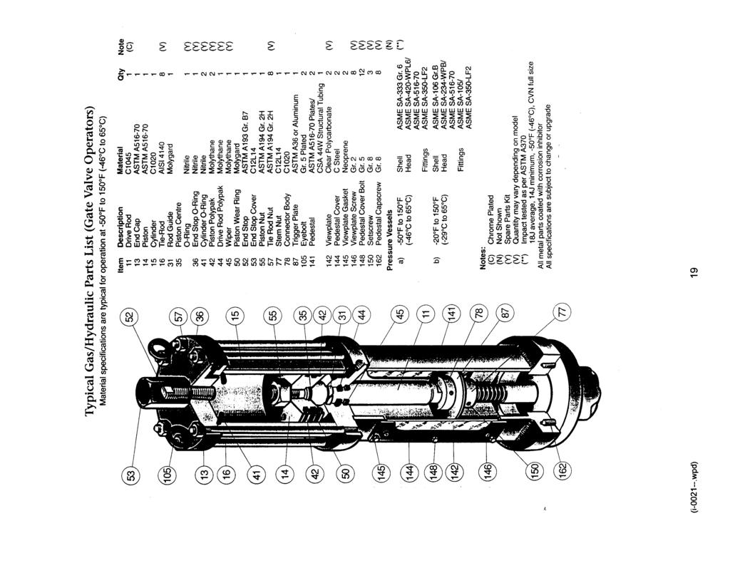
22 XV OPERATOR REPAIR KITS BILL OF MATERIALS MASTER LIST NOTE: Please provide the - MODEL - SERIAL NO. when ordering operator repair parts. (The W.O. number from Gas / Hydraulic tank tag, pressure vessel serial number and year of manufacture, or this manual, will help if no other identification information is obtainable.) Description - Operator Repair Kit - Minor Soft Parts Description Material Qty O-Ring Piston Center Nitrile 1 O-Ring End Stop Nitrile 1 Polypak Drive Rod Molythane 1 O-Ring Cylinder Nitrile 2 Polypak Piston Molythane 2 Polypak Drive Rod Molythane 1 Wiper Molythane 1 Description - Operator Repair Kit - Major, add: Description Material Qty Piston Wear Ring Molygard 1 Drive Rod Guide Molygard 1 NOTE: All soft parts from Minor Kit would be included in Major Kit. Description - Control Package Component Repair Kits See Specific Component drawings in service manual for indicated spare parts. Sold as a kit only. STAY ROD NUT TORQUE CYLINDER AIR HYD. (LB-FT) 1/ / / / / / /2 HXSC JACKNUT 100 5/8 HXSC JACKNUT 185 7/8 HXSC JACKNUT 450 (i wpd) 22
23 XVI TROUBLE SHOOTING Of all the system components the OPERATOR itself is the least likely to malfunction, and requires the most time and effort to service. For this reason a thorough effort should be made to pinpoint the source of trouble before proceeding with operator service. Completion of the operational test steps on pages 13 through 14 should confirm satisfactory operation or indicate the most likely source of a problem. PROBLEM POSSIBLE CAUSES REMEDY Slow jerky or partial stroke on manually controlled gas powered Slow or no operation with handpump - Low supply pressure - Shutoff / speed control closed - Dirty gas filter element resulting in insufficient flow and pressure to stroke operator - Contaminated oil; will not flow easily thru lines. - Operator and valve stops not in same position. - Tank oil levels low - Pump suction or discharge check valve malfunction - Speed control or locking valve blockage / malfunction - Dirt, ice in fluid lines - Check and increase - Check and open a few turns - Blow out lines - See section on Maintenance and Operational testing. Disconnect operator from valve if possible. - Make up levels with aviation grade hydraulic fluid (ESSO UNIVIS or EQUIVALENT; or per customer specification). - See GENERAL SERVICE section - Remove tubing at cylinder check for flow when handpump operated. Oil leaking from cylinder plate -Damaged rod seal -See OPERATOR SERVICE section Oil leaking from END STOP COVER SEAL Excessive amounts of oil thru exhaust -Damaged seal -High tank levels -Blow by across piston -See OPERATOR SERVICE regarding end stop seal replacement - Check levels - See MAINTENANCE AND OPERATIONAL TEST Manual operation with handpump (i wpd) 23
24 XVII GENERAL SERVICE NOTES Refer to: SCHEMATIC DRAWING(S); LIST OF COMPONENTS WITH PAGES 13 AND 14 PRECEDING; TESTING AND TROUBLE SHOOTING SECTION; The following pages contain information on the components identified on the schematic drawing of an Bettis Gas / Hydraulic Gate Valve Operator. Information on additional optional components as specified by users, is at the end of this manual. Please provide operator serial number if ordering spare parts. ITEM NO. COMPONENT 1 Bettis LINEAR OPERATOR Operates gate valves. Refer to "Operator Service". 3 GAS / HYDRAULIC TANKS For pressure transfer. Refer to I on page 21. Drain accumulated moisture and contaminants. An aviation grade hydraulic fluid (ESSO UNIVIS or a suitable equivalent) is used in all Bettis operator systems; or per customer request. 4 Bettis RELAY MODEL 324-M Lever operated to direct power gas to GAS / HYDRAULIC TANK. Soft parts replacement is required. Refer to cutaway drawing and parts list. 5 Bettis RELAY MODEL 324-DM Lever or diaphragm operated to direct power to GAS / HYDRAULIC TANK. Soft parts replacement is required. Refer to cutaway drawing and parts list. 6 Bettis HYDRAULIC SELECTOR VALVE Lever operated to select flow direction of hydraulic fluid. Drain GAS / HYDRAULIC TANK below selector valve level if valve must be removed. Refer to cutaway drawing and parts list. 7 SPEED FLOW CONTROL VALVE A variable orifice restriction which allows for independent control of opening and / or closing speed. 8 MANIFOLD CHECK VALVES Prevents interflow between tanks. Refer to A-0197 on page Bettis HANDPUMP Manual operation without power gas. Plunger seal and wiper may be easily replaced. Specify model number when ordering. 10 GAS FILTER Power gas filtration and liquids dropout. Blow down moisture and contaminants as required. Filter element may be replaced. Refer to cutaway drawing and parts list. 12 REGULATOR Provide signal gas for devices operating at 700 kpa (100 psi). On some models the seat block may be rotated to bring a new seating surface into use. (i wpd) 24
25 GENERAL SERVICE NOTES continued... ITEM NO. COMPONENT 13 RELIEF Signal gas overpressure protection. 15 END OF STROKE VALVE (trigger valve; N.O. relay) Cam operated at end of stroke to vent power gas. Normally only soft parts replacement is required. Refer to cutaway and parts list. 17 LIMIT SWITCH Electrical indication of valve status. Consult limit switch bulletin for service and adjustments. Specify make and model when ordering parts. 26 LOCKING VALVE Locking valve maintains operator and line gate valve in position by holding fluid in the cylinder after power gas is vented. Provide model and serial number if requesting spares or assistance. 37 HANDPUMP SAFETY VALVE Protection against handpump actuation when accidentally operating with power gas with open or close hydraulic selector valve positioned in handpump mode. (i wpd) 25
26
27

28

29
30
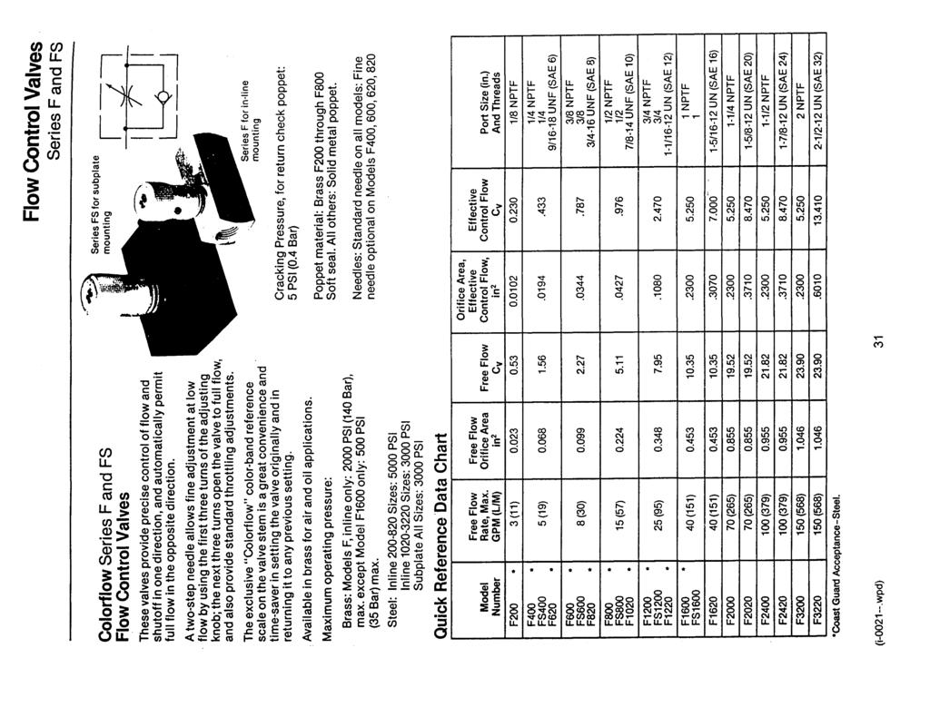
31
32
33
34
35 XVIII VH LOCKING BLOCK ADJUSTMENT AND SERVICE A) Scope: This document describes field inspection and rebuild of the series VH1 and VH2 Hydraulic Valve. Some models do not include or require the relief valve components, in which case references to these components should be ignored. B) Reference Drawing: APB0662 LOCKING BLOCK SERIES VH, ASSEMBLY. C) Materials: 1. Spare parts kit (P.N. SPRK-VH2 or SPRK-VH1). When ordering kits, specify the serial and / or reference numbers found on the operator as well as the model number on the VH series valve. 2. Vaseline. D) Dismantling and inspection: The valve body may be left in place or removed for the following: 1. Drain oil as required, note the position of the relief valve adjust screws and remove all parts from the block except relief valve seat inserts, NPT plugs and tube fittings. 2. Inspect the following items in the body: a) poppet seats, relief valve seat inserts for smooth undamaged surface. NOTE: Relief valve seat inserts have been installed with "PST" or equivalent pipe sealant at the factory. b) piston bores for smooth, unscratched surface. 3. Remove all o-rings and inspect the following on the parts: a) piston subassembly for tight piston-to-spring rod threaded joint (compress spring for visual examination). NOTE: The joint has been torqued to 10 ft.lb and blue "Loctite" has been applied at the factory. b) piston OD for smooth finish. c) springs for corrosion, breakage or distortion. E) Rebuild: a) Clean any accumulations of dirt or sediment (removal of NPT plugs may be required). b) Install new soft parts with vaseline lubricant. Re-install all parts into the body. F) Adjustment of relief valves: Set relief valve adjust screws approximately (to position noted at disassembly). With tank ports open, apply pressure to the cylinder ports (C1 and C2 in turn) to set the corresponding relief valves. Raise pressure slowly until a small flow is seen from the tank port (after flooding the tank side of the body as necessary). Adjust the relief valve adjust screw as required. (i wpd) 35
36

37
38
39
40

41

42
43
44
45 XIV LINEAR GAS / HYDRAULIC OPERATOR NOTES (i wpd/45 orig: dh rev5:aa/mc app dist:(ef)o);(slc)p)
SERVICE MANUAL No. I-0019
 Bettis Canada Ltd. 4112 91A Street Edmonton, Alberta, Canada T6E 5V2 Tel: (403) 450-3600 Fax: (403) 450-1400 SERVICE MANUAL No. I-0019 Edmonton CUSTOMER: P.O.#: W.O.#: TAG: DATE: APPLIES TO OPERATOR MODEL:
OCTOPUS SERVICE PROCEDURE - SP007 REV NEW 15-FEB-2008
 OCTOPUS SERVICE PROCEDURE - SP007 REV NEW 15-FEB-2008 APPLICABLE MODELS a. Both styles of Octopus Hydraulic 38mm Bore Linear Drive. (LAM = Linear Actuator Mounted & LAR = Linear Actuator Remote) REQUIRED
SERVICE MANUAL No. I-0220
 Bettis Canada Ltd. 4112 91A Street Edmonton, Alberta, Canada T6E 5V2 Tel: (780) 450-3600 Fax: (780) 450-1400 SERVICE MANUAL No. I-0220 Edmonton PRESSUREMATIC CUSTOMER: P.O.#: W.O.#: TAG: DATE: APPLIES
INSTALLATION, OPERATION AND MAINTENANCE MANUAL (IOM)
") INSTALLATION, OPERATION AND MAINTENANCE MANUAL (IOM) IOM-1088 03-16 Model 1088 Vacu-Gard Blanketing Valve ISO Registered Company SECTION I I. DESCRIPTION AND SCOPE The Model 1088 Vacu-Gard is a tank blanketing
INSTALLATION, OPERATION AND MAINTENANCE MANUAL (IOM) IOM-1088 03-16 Model 1088 Vacu-Gard Blanketing Valve ISO Registered Company SECTION I I. DESCRIPTION AND SCOPE The Model 1088 Vacu-Gard is a tank blanketing
DO NOT INSTALL, OPERATE, OR MAINTAIN AN ATI PRODUCT UNLESS TRAINED AND QUALIFIED IN PRODUCT AND ACCESSORY INSTALLATION, OPERATION AND MAINTENANCE.
 IOM Supplement IOMS003 ATI HO1/HO2 HYDRAULIC OVERRIDE Scope of Supplement This supplement is intended to assist those who are involved with the installation, operation and maintenance of ATI Linear Actuators
CAB TILT HYDRAULIC SYSTEM
 OPERATION, MAINTENANCE and SERVICE INSTRUCTIONS CAB TILT HYDRAULIC SYSTEM WITH POWER-PACKER PUMP, CYLINDERS and LATCHES A division of Actuant Corporation 1-800-745-4142 1 www.powerpackerus.com Notice The
OPERATING INSTRUCTIONS & SERVICE MANUAL BLUE MAX II HYDROSTATIC TEST PUMP
 PAGE 1 OF 10 OPERATING INSTRUCTIONS & SERVICE MANUAL BLUE MAX II HYDROSTATIC TEST PUMP EFFICIENT, EASY OPERATION Air operated pump Wide range of pressures and volumes Easy to operate controls Output pressure
Purging Air From Divider Block Lubrication Systems
 FROST ENGINEERING SERVICE Purging Air From Lubrication Systems A D I V I S I O N O F G E C S E Y S A L E S & S E R V I C E DESCRIPTION Divider block lubrication systems operate correctly only when all
Baumann Series Flexsleev Control Valve Instructions
 Instruction Baumann 86000 Series Instructions Baumann 86000 Series Flexsleev Control Valve Instructions Contents Introduction...1 Scope...1 Safety Precautions...1 Maintenance...2 Installation...3 Air Piping...3
Ideal Installation. I & M Mark 67 (1/2 6 ) Control Line. Installation & Maintenance Instructions for Mark 67 Pressure Regulators
 Control Line. Installation & Maintenance Instructions for Mark 67 Pressure Regulators") I & M Mark (/ ) 0 Wasson Road Cincinnati, OH 0 USA Phone --00 Fax -8-00 info@richardsind.com www.jordanvalve.com Installation & Maintenance Instructions for Mark Pressure Regulators Warning: Jordan Valve
I & M Mark (/ ) 0 Wasson Road Cincinnati, OH 0 USA Phone --00 Fax -8-00 info@richardsind.com www.jordanvalve.com Installation & Maintenance Instructions for Mark Pressure Regulators Warning: Jordan Valve
GH-BETTIS OPERATING & MAINTENANCE INSTRUCTIONS DISASSEMBLY & ASSEMBLY FOR THE T80X-M4-S DOUBLE ACTING SERIES HYDRAULIC ACTUATORS
 GH-BETTIS OPERATING & MAINTENANCE INSTRUCTIONS DISASSEMBLY & ASSEMBLY FOR THE T80X-M4-S DOUBLE ACTING SERIES HYDRAULIC ACTUATORS -S INDICATES CYLINDERS ARE IN TANDEM PART NUMBER: 100121 REVISION "A" ECN
OPERATION AND PARTS MANUAL
 OPERATION AND PARTS MANUAL MODEL NUMBER : PART NUMBER : GTL 1110 1900-0510 SERIAL NUMBER : BAYNE MACHINE WORKS, INC. PHONE: (864) 288-3877 910 FORK SHOALS ROAD TOLL FREE: (800) 535-2671 GREENVILLE S.C.,
Fisher 657 Diaphragm Actuator Sizes and 87
 Instruction Manual 657 Actuator (30-70 and 87) Fisher 657 Diaphragm Actuator Sizes 30 70 and 87 Contents Introduction... 1 Scope of Manual... 1 Description... 2 Specifications... 2 Installation... 3 Mounting
ACHL Series Pump. Operation and Maintenance Manual Air Driven, Hand Operated High Pressure Liquid Pump
 ACHL Series Pump Operation and Maintenance Manual Air Driven, Hand Operated High Pressure Liquid Pump Catalog: 02-9245ME February 2013 Model # Serial # Drawing # Order # Mfg. Date Table of Contents page
MOREHOUSE INSTRUMENT COMPANY, INC. 60,000 LBS CAPACITY AIRCRAFT PART NUMBER SCALE S FORCE CALIBRATION PRESS PART NO.
 INDEX 1. GENERAL SPECIFICATION AND DRAWING 804000-03... 2 2. ASSEMBLY INSTRUCTIONS... 5 3. OPERATING INSTRUCTIONS... 6 4. MAINTENANCE INSTRUCTIONS... 7 5. CERTIFICATE OF CAPACITY LOAD TEST AND OVERLOAD...
I & M MK96 & MK96C. Ideal Installation. Start-Up. Maintenance PROTECT VALVES WITH LINE STRAINERS
 **VIP** If you purchased your MK96 or MK96C Valve, or any stem repair component for this valve, after 9/7/08 - please see **VIP** assembly instruction change on page, middle-right, section. I & M MK96
SD Bendix E-10PR Retarder Control Brake Valve DESCRIPTION. OPERATION - Refer to Figure 2
 SD-03-832 Bendix E-10PR Retarder Control Brake Valve MOUNTING PLATE SUPPLY 4 PORTS ELECTRICAL AUXILIARY DESCRIPTION TREADLE RETARDER CONTROL SECTION EXHAUST DELIVERY 4 PORTS FIGURE 1 - E-10PR RETARDER
33 CENTERVILLE ROAD LANCASTER, PA
 33 CENTERVILLE ROAD LANCASTER, PA 17603-2064 TEL: (717) 509-2200 FAX: (717) 509-2336 INSTALLATION, OPERATION AND MAINTENANCE INSTRUCTIONS MODEL T2005 & T2006 SKOTCH TRIFECTA OIL VALVE SYSTEMS WARNING Valves
ANDERSON GREENWOOD SERIES 500 PILOT OPERATED SAFETY RELIEF VALVES INSTALLATION AND MAINTENANCE INSTRUCTIONS
 Before installation these instructions must be fully read and understood TABLE OF CONTENTS 1. General valve description and start-up... 1 2. Main valve maintenance... 1 3. Pilot maintenance... 5 4. Pilot
GH-BETTIS SERVICE INSTRUCTIONS DISASSEMBLY & REASSEMBLY FOR MODELS HD521-M4, HD721-M4 AND HD731-M4 DOUBLE ACTING SERIES PNEUMATIC ACTUATORS
 GH-BETTIS SERVICE INSTRUCTIONS DISASSEMBLY & REASSEMBLY FOR MODELS HD521-M4, HD721-M4 AND HD731-M4 DOUBLE ACTING SERIES PNEUMATIC ACTUATORS WITH HYDRAULIC CONTROL PACKAGE PART NUMBER: SE-023 REVISION:
OPERATION AND PARTS MANUAL
 OPERATION AND PARTS MANUAL MODEL NUMBER : PART NUMBER : TAP- IN KIT 5100-5151 BAYNE MACHINE WORKS, INC. PHONE: (864) 288-3877 910 FORK SHOALS ROAD TOLL FREE: (800) 535-2671 GREENVILLE S.C., 29605 FAX:
THE LF-690 SERIES. Operating and Service Manual. Series includes all variants of LF-690/691 and 692
 THE LF-690 SERIES Operating and Service Manual Series includes all variants of LF-690/691 and 692 Issue C March 2014 1 TABLE OF CONTENTS 1. Description... 3 2. Installation... 3 3. Operation... 4 4. Special
Baumann Sanitary Diaphragm Angle and Inline Control Valve
 Instruction Manual 84000 Valve Baumann 84000 Sanitary Diaphragm Angle and Inline Control Valve Contents Introduction... 1 Scope of Manual... 1 Safety Precautions... 2 Maintenance... 2 Flow Direction...
Operating & Maintenance Manual For Steam Conditioning Valve
 For Steam Conditioning Valve 1 Table of Contents 1.0 Introduction 3 2.0 Product description 3 3.0 Safety Instruction 4 4.0 Installation and Commissioning 5 5.0 Valve Disassembly 6 6.0 Maintenance 6 7.0
Fisher 3024C Diaphragm Actuator
 Instruction Manual 3024C Actuator Fisher 3024C Diaphragm Actuator Contents Introduction... 1 Scope of Manual... 1 Description... 2 Specifications... 3 Installation... 5 Mounting the Actuator on the Valve...
I & M Mark 708ME. Ideal Installation. Start-Up Procedure. Installation & Maintenance Instructions for Mark 708 & Motor Actuator
 I & M Mark 708ME 3170 Wasson Road Cincinnati, OH 45209 USA Phone 513-533-5600 Fax 513-871-0105 info@richardsind.com www.lowfl owvalve.com Installation & Maintenance Instructions for Mark 708 & Motor Actuator
Operation and Maintenance Instructions for Bettis GVO-C Series GVO-CLP-SR Pneumatic Actuators
 Part Number: GVO-CLP-SR.IOM.1003, Rev. 0 Release: March 2016 Operation and Maintenance Instructions for Bettis GVO-C Series GVO-CLP-SR Pneumatic Actuators Part Number: GVO-CLP-SR.IOM.1003, Rev. 0 Table
MP18 Stacking Valve System Technical Information Manual
 Electric Drives and Controls Hydraulics Linear Motion and Assembly Technologies Pneumatics Service MP18 Stacking Valve System Technical Information Manual The Drive & Control Company Copyright 1996 Bosch
HIGH PRESSURE CONTROL VALVE R2L ACTUATOR
 R2L ACTUATOR All Rights Reserved. All contents of this publication including illustrations are believed to be reliable. And while efforts have been made to ensure their accuracy, they are not to be construed
AMIAD Automatic Filters
 1. Model EBS AMIAD Automatic Filters Maintenance Guidelines General inspection In order to check the proper operation of the filter, close the low-pressure 1/4" valve to the pressure differential switch
OCTOPUS SELECTION & INSTALLATION GUIDE
 OCTOPUS SELECTION & INSTALLATION GUIDE CRB SERIES CONTINUOUS RUNNING PUMPSET A. GENERAL DESCRIPTION: Octopus CRB pumpsets are heavy duty, continuously running, electric motor driven pumps which are used
Installation and Service Manual Hydraulic Cab Tilt System
 An Actuant Company Installation and Service Manual Hydraulic Cab Tilt System CONTENTS 1.0 Receiving Instructions 2 2.0 Safety Issues 2 3.0 Hydraulic Fluid and Grease 3 4.0 Description 4 5.0 Operation 6
Bray/ VAAS Slurry Series Knife Gate Valve 760/762/765/766/767/768 Series Operation and Maintenance Manual
 Bray/ VAAS Knife Gate Valve 760/762/765/766/767/768 Series Table of Contents Definition of Terms 1 Safety Instructions 1 Introduction 2 Unpacking 2 Storage 2 Installation 3 Commissioning 3 Cylinder-Operated
Anderson Greenwood Series 400 Piston Pilot POPRV Installation and Maintenance Instructions
 Before installation these instructions must be fully read and understood As capacity relief of the system is satisfied, system pressure will begin to decrease. When it does, the pilot will actuate and
Model DFR 070/156/220 Rotary Actuator
 Figure 1 DFR 156 TABLE OF CONTENTS General 2 Actuator Assembly 18 Scope 2 Bushing / Yoke Assembly 18 Principles of Operation 2 Spring Barrel Assembly 18 Safety Caution 2 Diaphragm Plate Assembly 20 Specifications
I & M 8000 Series. Ideal Installation Schematic. Preferred Installation. Trouble Shooting
 I & M 8000 Series 3170 Wasson Road Cincinnati, OH 45209 USA Phone 513-533-5600 Fax 513-871-0105 lowflow@richardsind.com www.lowflowvalve.com Installation & Maintenance Instructions for 8000 Series Low
GVO-LP-SR/FS Spring Return. Installation, Operation and Maintenance Manual E Rev. A May 2014
 GVO-LP-SR/FS Spring Return Installation, Operation and Maintenance Manual E-90090003 Rev. A May 2014 Installation, Operation and Maintenance Manual E-90090003 Rev. A Table of Contents May 2014 Table of
SERVICE INSTRUCTIONS ASSEMBLY & DISASSEMBLY T50X DOUBLE ACTING HYDRAULIC SERIES ACTUATORS
 Page 1 of 7 SERVICE INSTRUCTIONS ASSEMBLY & DISASSEMBLY T50X DOUBLE ACTING HYDRAULIC SERIES ACTUATORS INTRODUCTION This service procedure is offered as a guide to enable general maintenance to be performed
OPERATION AND PARTS MANUAL
 OPERATION AND PARTS MANUAL MODEL NUMBER : PART NUMBER : GRL 1110 1900-0540 SERIAL NUMBER : BAYNE MACHINE WORKS, INC. PHONE: 864.288.3877 910 FORK SHOALS ROAD TOLL FREE: 800.535.2671 GREENVILLE SC, 29605
Actuator Control Manual with ESD Valve
 ActCont Manual with ESD Actuator Control Manual with ESD Valve Replacement Procedure on a Rotary Vane Actuator with a System using Power Gas The purpose of this procedure is to guide the replacement of
CVS Series 35, 50, 60, 70. Scotch Yoke Hydraulic Actuators. Introduction. Instruction Manual
 Instruction Manual Figure 1: CVS Series 35 SRM100 Actuator CVS Series 35, 50, 60, 70 Scotch Yoke Hydraulic Actuators Introduction The CVS Hydraulic Actuator uses a scotch yoke mechanism to convert linear
Installation Manual For ISL98, ISL03, ISL07, ISC07
 Installation Manual For ISL98, ISL03, ISL07, ISC07 Table of Contents Section 1: Introduction... 3 Housing Identification... 3 Engine Identification... 3 Special Tools... 3 Automatic Transmissions... 3
4 - Way Control 4 - Way Control 4 - Way Control with lock
 INSTALLATION / OPERATION / MAINTENANCE 1. DESCRIPTION MODEL 0-02 (Full Internal Port) Powertrol Valve This manual contains information for installation, operation and maintenance of the Cla-Val Co. 0-02
TECHNICAL DATA. Q= C v P S
 1 of 9 1. DESCRIPTION The Viking Model E-1 Deluge Valve is a quick-opening, differential diaphragm, flood valve with one moving part. The deluge valve is used to control water flow in deluge and preaction
PRESSURE REGULATOR BACK PRESSURE TO ATMOSPHERE WITH OUTSIDE SUPPLY
 PRESSURE REGULATOR BACK PRESSURE TO ATMOSPHERE WITH OUTSIDE SUPPLY All Rights Reserved. All contents of this publication including illustrations are believed to be reliable. And while efforts have been
Scope. Applicability. Caution. I & M CV3000 Series. Storage. Installation & Maintenance Instructions for Marwin CV3000 Series Three Piece Ball Valves
 I & M CV3000 Series 3170 Wasson Road Cincinnati, OH 45209 USA Phone 513-533-5600 Fax 513-871-0105 marwin@richardsind.com www.marwinvalve.com Installation & Maintenance Instructions for Marwin CV3000 Series
I & M Mark 78 Series. Ideal Installation. Start-Up. Installation & Maintenance Instructions for Mark 78 Control Valves (1/2-1 )
") I & M Mark 8 Series 30 Wasson Road Cincinnati, OH 4509 USA Phone 53-533-5600 Fax 53-8-005 info@richardsind.com www.jordanvalve.com Installation & Maintenance Instructions for Mark 8 Control Valves (/ -
I & M Mark 8 Series 30 Wasson Road Cincinnati, OH 4509 USA Phone 53-533-5600 Fax 53-8-005 info@richardsind.com www.jordanvalve.com Installation & Maintenance Instructions for Mark 8 Control Valves (/ -
High Lift Transmission Jack
 SPX Corporation 655 Eisenhower Drive Owatonna, MN 55060-0995 USA Phone: (507) 455-7000 Tech. Serv.: (800) 533-6127 Fax: (800) 955-8329 Order Entry: (507) 455-1480 Fax: (800) 283-8665 International Sales:
Baumann Mikroseal Control Valve
 Instruction Manual 81000 Valve Baumann 81000 Mikroseal Control Valve Contents Introduction... 1 Scope of Manual... 1 Safety Precautions... 2 Maintenance... 3 Installation... 3 Air Piping... 4 Flow Direction...
To ensure proper installation, digital pictures with contact information to before startup.
 Check List for Optimal Filter Performance? There should be no back-pressure on the flush line. A 1 valve should have a 2 waste line, and 2 valve should have a 3 waste line. Do not use rubber hosing or
ANDCO Eagle Actuator Instruction Manual
 ANDCO Actuators ANDCO Eagle Actuator Instruction Manual The information contained in this manual is essential to safe, successful, long term operation of your Andco Eagle Linear Actuator. Read and follow
Product Maintenance Information
 Product Maintenance Information Air Balancers Series ZA, EA, and BA (Dwg. MHP2176) Save These Instructions Form 16598856 Edition 3 August 2011 2011 Ingersoll-Rand Company Only allow Ingersoll Rand trained
TECHNICAL DATA. Q= C v P Cv = Flow Factor (GPM/1 PSI P)
") 1 of 9 1. DESCRIPTION The Viking 2 (DN50) is a quick-opening, differential diaphragm, flood valve with one moving part. The deluge valve is used to control water flow in deluge and preaction sprinkler
1 of 9 1. DESCRIPTION The Viking 2 (DN50) is a quick-opening, differential diaphragm, flood valve with one moving part. The deluge valve is used to control water flow in deluge and preaction sprinkler
Model DF233 Control Valve
 Figure 1 DF233 Control Valve TABLE OF CONTENTS Introduction 2 Body and Packing Reassembly 7 Specifications 3 Fail Closed Actuator Reassembly 8 Valve Sizes 3 Fail Open Actuator Reassembly 9 Unpacking 4
Val-Matic Air / Oil Hydraulic Panel Pump Control System. Operation, Maintenance and Installation Manual
 Manual No. 5AOP-OM1-2 Val-Matic Air / Oil Hydraulic Panel Pump Control System Operation, Maintenance and Installation Manual INTRODUCTION... 1 RECEIVING AND STORAGE... 1 DESCRIPTION OF OPERATION... 1 INSTALLATION...
Fisher 1061 Pneumatic Piston Rotary Actuator with Style H & J Mounting Adaptations
 Instruction Manual 1061 H & J Actuator Fisher 1061 Pneumatic Piston Rotary Actuator with Style H & J Mounting Adaptations Contents Introduction... 1 Scope of Manual... 1 Description... 2 Specifications...
TECHNICAL DATA 1-1/2 (dn40)
") July 1, 2011 Deluge Valves 209a DESCRIPTION The Viking Model E-3 1-1/2 Deluge Valve is a quick-opening, differential type flood valve with a rolling diaphragm clapper. The deluge valve is used to control
July 1, 2011 Deluge Valves 209a DESCRIPTION The Viking Model E-3 1-1/2 Deluge Valve is a quick-opening, differential type flood valve with a rolling diaphragm clapper. The deluge valve is used to control
Q= C. v P S Refer to Table 1 for part numbers and shipping weights. Accessories: Table 1: Valve Part Numbers and Specifications
 1 of 9 1. DESCRIPTION The Viking Flow Control Valve is a quick opening, differential diaphragm flood valve with a spring loaded floating clapper. The Flow Control Valve can be used to facilitate manual
Flow Control & Pressure Reducing Valve with Hydraulic Control (Sizes 3''- 12"; DN80-DN300)
") IOM IR-472-50-bRU Flow Control & Pressure Reducing Valve with Hydraulic Control (Sizes 3''- 12"; DN80-DN300) Description: The BERMAD Flow Control and Pressure Reducing Valve with Hydraulic Control is a
IOM IR-472-50-bRU Flow Control & Pressure Reducing Valve with Hydraulic Control (Sizes 3''- 12"; DN80-DN300) Description: The BERMAD Flow Control and Pressure Reducing Valve with Hydraulic Control is a
Valtek Auxiliary Handwheels and Limit Stops
 Valtek Auxiliary s and Limit Stops Table of Contents Page 1 General information 2 Installation 2 Side-mounted handwheels, size 25 and 50 (linear actuators) 3 Side-mounted handwheels, size 100 and 200 (linear
LOW PRESSURE BALANCED VALVE DIAPHRAGM BALANCED
 DIAPHRAGM BALANCED All Rights Reserved. All contents of this publication including illustrations are believed to be reliable. And while efforts have been made to ensure their accuracy, they are not to
MP18/SIC & SIO Stacking Valve System Technical Information Manual
 Electric Drives and Controls Hydraulics Linear Motion and Assembly Technologies Pneumatics Service MP18/SIC & SIO Stacking Valve System Technical Information Manual The Drive & Control Company Copyright
I & M Mark 78 Series. Ideal Installation. Start-Up. Installation & Maintenance Instructions for Mark 78 Control Valves (1-1/2-2 )
") I & M Mark 8 Series 0 Wasson Road Cincinnati, OH 4509 USA Phone 5-5-5600 Fax 5-8-005 info@richardsind.com www.jordanvalve.com Installation & Maintenance Instructions for Mark 8 Control Valves (-/ - ) Warning:
I & M Mark 8 Series 0 Wasson Road Cincinnati, OH 4509 USA Phone 5-5-5600 Fax 5-8-005 info@richardsind.com www.jordanvalve.com Installation & Maintenance Instructions for Mark 8 Control Valves (-/ - ) Warning:
DeZURIK SPRING RETURN CYLINDER OPERATOR FOR G-SERIES ACTUATORS USED ON PEF 100% PORT ECCENTRIC VALVES
 SPRING RETURN CYLINDER OPERATOR FOR G-SERIES ACTUATORS USED ON PEF 100% PORT ECCENTRIC VALVES Instruction D10466 December 2012 Instructions These instructions provide information about s. They are for
EQUALIZER International Limited 10T(I) Integral Hydraulic Spreading Wedge Repair Instruction Manual
 Integral Hydraulic Spreading Wedge Repair Instruction Manual") EQUALIZER International Limited 10T(I) Integral Hydraulic Spreading Wedge Repair Instruction Manual INDEX THE EQUALIZER 10T(I) Integral Hydraulic Wedge SECTION CONTENTS PAGE NO (S) 03 04 05 06 07 08 09
EQUALIZER International Limited 10T(I) Integral Hydraulic Spreading Wedge Repair Instruction Manual INDEX THE EQUALIZER 10T(I) Integral Hydraulic Wedge SECTION CONTENTS PAGE NO (S) 03 04 05 06 07 08 09
HIGH PRESSURE CONTROL VALVE PISTON BALANCED
 PISTON BALANCED All Rights Reserved. All contents of this publication including illustrations are believed to be reliable. And while efforts have been made to ensure their accuracy, they are not to be
DISPLACEMENT PUMP INSTRUCTIONS-PARTS LIST Rev. K. Model , Series A Model , Series B Model , Series A
 INSTRUCTIONS-PARTS LIST INSTRUCTIONS This manual contains important warnings and information. READ AND KEEP FOR REFERENCE. DISPLACEMENT PUMP 308190 Rev. K 3000 psi (210 bar) MAXIMUM WORKING PRESSURE Model
AIR/HYDRAULIC INJECTION GUN MODEL INSTRUCTIONS
 I. OPERATION & DESCRIPTION The Air / Hydraulic Injection Gun is a high-pressure tool that should be used with caution and according to these instructions. IMPORTANT: The Gun is 0,000 psi rated. Do not
STEERING HYDRAULICS The steering system is a flow amplified, load sensing, hydraulics arrangement.
 STEERING HYDRAULICS 116821 The steering system is a flow amplified, load sensing, hydraulics arrangement. When the steering wheel is turned, the Steering Metering Pump meters an oil volume proportional
SERIES G3DB/AG3DB ELEVATOR
 TM INSTRUCTIONS AND PARTS LIST SERIES G3DB/AG3DB ELEVATOR WARNING This manual, and GENERAL INSTRUCTIONS MANUAL, CA-1, should be read thoroughly prior to pump installation, operation or maintenance. SRM00059
Pilot-Operated Regulators
 Fisher Controls Instruction Manual Type 1098-EGR & 1098H-EGR Pilot-Operated Regulators R May 1987 Form 5084 Contents Introduction................................... 2 Scope of Manual..............................
Model 8329 Table of Contents
 SERVICE & OPERATING MANUAL Original Instructions Instructions Sheet: 670991 Model 8329 Table of Contents Engineering Data and Temperature Limitations... 1 Performance Curve... 2 Dimensions... 3 Metric
Table 6-1. Problems and solutions with pump operations. No Fluid Delivery
 Table 6-1. and solutions with pump operations No Fluid Delivery Fluid level in the reservoir is low. Oil intake pipe or inlet filter is plugged. Air leak in the inlet line prevents priming or causes noise
SD Bendix E-12 & E-15 Dual Brake Valve DESCRIPTION
 SD-03-6 Bendix E- & E-15 Dual Brake Valve TREADLE UPPER BODY ASSEMBLY PRIMARY DELIVERY ( ) 1 SECONDARY DELIVERY ( ) LOWER BODY ASSEMBLY MOUNTING PLATE PRIMARY SUPPLY ( SUP-1) PRIMARY SUPPLY ( SUP-) PRIMARY
MAINTENANCE MANUAL FOR THERMOSTATIC TEMPERATURE REGULATING VALVE TRAC STYLE P
 MANUAL NUMBER P-EFS-1 MAINTENANCE MANUAL FOR THERMOSTATIC TEMPERATURE REGULATING VALVE TRAC STYLE P TRAC Regulator Company Inc. 160 South Terrace Avenue Mount Vernon, New York USA 10550-2408 Phone: (914)
OCTOPUS SELECTION & INSTALLATION GUIDE Rev. C CRA SERIES CONTINUOUS RUNNING PUMPSET
 A. GENERAL DESCRIPTION: OCTOPUS SELECTION & INSTALLATION GUIDE Rev. C CRA SERIES CONTINUOUS RUNNING PUMPSET Octopus CRA continuous running pumps are very reliable quiet and efficient devices which will
Model DF269 Control Valve
 Figure 1 DF269 Control Valve TABLE OF CONTENTS Introduction 2 Fail Open Actuator Disassembly 6 General 2 Body and Packing Reassembly 7 Scope 2 Fail Closed Actuator Resassembly 8 Specifications 3 Fail Open
Post Driver Attachment
 Attachment (Shown with Optional Power Cell Rotator) Models - 600, 850 Safety Instructions This safety alert symbol indicates important safety messages in this manual. When you see this symbol, carefully
Instruction Manual & Parts List For H/G323FXFSX-500_ & 800_ Pumps With Flowserve Type BX Cartridge Seal
 TM Instruction Manual & Parts List For H/G323FXFSX-500_ & 800_ Pumps With Flowserve Type BX Cartridge Seal WARNING This Special Instruction Manual and General Instructions Manual, CA-1, should be read
NECO Pumping Systems
 INSTALLATION OPERATION & MAINTENANCE INSTRUCTIONS For Your NECO Pumping Systems PACKAGED CIRCULATING SYSTEM THIS COMPLETELY ASSEMBLED, TESTED, PACKAGED CIRCULATING SYSTEM IS OF THE HIGHEST QUALITY AND
Tooling Assistance Center
 Safeguards are designed into this application equipment to protect operators and maintenance personnel from most hazards during equipment operation. However, certain safety precautions must be taken by
Flow Line Controls. Installation & Operations Manual SERIES 20/21 Pneumatic Actuators
 Flow Line Controls Installation & Operations Manual SERIES 20/21 Pneumatic Actuators Flow Line Controls, Inc. P.O. Box 677 Schriever, LA 70395 Phone: 985-414-6003 Toll Free 1-800-815-9226 Fax 985-414-6072
Fisher 2052 Diaphragm Rotary Actuator
 Instruction Manual 2052 Actuator Fisher 2052 Diaphragm Rotary Actuator Contents Introduction... 1 Scope of Manual... 1 Description... 1 Specifications... 4 Installation... 4 Actuator Mounting and Changing
High Lift Transmission Jack Max. Capacity: kg (1,000 lbs.)
") 655 EISENHOWER DRIVE OWATONNA, MN 55060-0995 USA PHONE: (507) 455-7000 TECH. SERV.: (800) 533-6127 FAX: (800) 955-8329 ORDER ENTRY: (800) 533-6127 FAX: (800) 283-8665 INTERNATIONAL SALES: (507) 455-7223
655 EISENHOWER DRIVE OWATONNA, MN 55060-0995 USA PHONE: (507) 455-7000 TECH. SERV.: (800) 533-6127 FAX: (800) 955-8329 ORDER ENTRY: (800) 533-6127 FAX: (800) 283-8665 INTERNATIONAL SALES: (507) 455-7223
IOM FOR DYNATORQUE D-LOCK LOCKING DEVICE (DL TYPE)
") Scope: It is the purpose of this document to provide general installation, operation, and maintenance instructions for the DYNATORQUE D-Lock locking device. Design: All Cameron DYNATORQUE operators and
Scope: It is the purpose of this document to provide general installation, operation, and maintenance instructions for the DYNATORQUE D-Lock locking device. Design: All Cameron DYNATORQUE operators and
1/2" AIR DRIVEN DIAPHRAGM PUMP
 1/2" DRIVEN DIAPHRAGM PUMP OPERATION AND SERVICE GUIDE O-1225D NOV. 2008 Page 1 of 6 Refer to Bulletin P-605, Parts List P-9151 DRIVEN, DOUBLE DIAPHRAGM PUMP MANUAL Congratulations on purchasing one of
FRP Ball Valves INSTALLATION & MAINTENANCE MANUAL
 FRP Ball Valves INSTALLATION & MAINTENANCE MANUAL FRP BALL VALVES TABLE OF CONTENTS MAINTENANCE AND INSTALLATION INSTRUCTIONS 1. 2. 2.1 2.2 2.3 2.4 GENERAL...Page 1 HANDLING...1 Receiving and Storing...1
INSTALLATION, OPERATION, AND MAINTENANCE MANUAL
 INSTALLATION, OPERATION, AND MAINTENANCE MANUAL MODEL 4D-200 REDUCED PRESSURE PRINCIPLE (RPZ) & MODEL 4D-700 REDUCED PRESSURE DETECTOR ASSEMBLY (RPDA) BACKFLOW PREVENTERS 2 ½ 10 Conbraco Industries Inc.
INSTRUCTION AND MAINTENANCE MANUAL FR95 PRESSURE REGULATOR
 Enidine / Conoflow 105 Commerce Way Westminster, SC 29693 Tel: (864) 647-9521 Fax: (864) 647-7993 WARNING Conoflow s products are designed and manufactured using materials and workmanship required to meet
348002K/348012K Manifold Block Style Service Manual 12/2000
 348002K/348012K Manifold Block Style Service Manual 12/2000 Service Manual 348002K/348012K Manifold Block Style Recovery/Recycling/Recharging Unit For R-12 or R-134a Only TABLE OF CONTENTS: Theory of Operation
CVS Type 667 Diaphragm Actuator Sizes 30-70
 Instruction Manual CVS Type 667 Diaphragm Actuator Sizes 30-70 All CVS Controls actuators are to be installed and maintained in accordance with instructions supplied by CVS Controls. This manual includes
PRODUCT OPERATING MANUAL
 PRODUCT OPERATING MANUAL PANBLAST TM CS37 SUCTION BLAST CABINET Manual Number: ZVP PC 0069 00 SECTION 1. GENERAL INFORMATION 2. ASSEMBLY & INSTALLATION INSTRUCTIONS 3. OPERATING INSTRUCTIONS 4. MAINTENANCE
DP5 Pump. 5:1, Air-operated, Heavy Duty, Oil. General. Operation. Technical Data. Installation R1 09/10
 DP5 Pump 5:1, Air-operated, Heavy Duty, Oil General The DP5 Pump is a compressed air-operated reciprocating piston medium pressure pump. These pumps are suitable for distribution of all types of light
Cla-Val. Service Training Manual. Simple solutions plus learning with a purpose
 Cla-Val Service Training Manual Simple solutions plus learning with a purpose 5 Application Series Section General Identify What Valve You Have 5-1 Rate of Flow 40 Series 5-2 Pressure Relief 50 Series
INSTALLATION MANUAL. MB-180, MB-210 and MB-210L Motor Brake INSTALLATION. Force Control Industries, Inc. DESCRIPTION OPERATION
 MB-180, MB-210 and MB-210L Motor Brake INSTALLATION MANUAL 512-180-001-00 DESCRIPTION Posistop Motor Brakes are multiple surface, spring activated, pneumatic release braking devices that effectively dissipate
PACKING, HANDLING, TRANSPORTING AND STORING MOTORS
 PACKING, HANDLING, TRANSPORTING AND STORING MOTORS Make sure that the shaft of the motor is not loaded in any way and is protected from knocks. Axial loads or shocks may easily damage the bearings inside
HOUSTON OILFIELD EQUIPMENT 9669 PORT ERROLL RD. HOUSTON, TX PHONE: (713) FAX: (713)
 FAX: (713)") HOUSTON OILFIELD EQUIPMENT 9669 PORT ERROLL RD. HOUSTON, TX 77095 PHONE: (713) 466-3797 FAX: (713) 466-3189 INSTALLATION AND MAINTENANCE INSTRUCTION MANUAL 10M CWP H-JWAl HPC ADJUSTABLE CHOKE AND POSITIVE
HOUSTON OILFIELD EQUIPMENT 9669 PORT ERROLL RD. HOUSTON, TX 77095 PHONE: (713) 466-3797 FAX: (713) 466-3189 INSTALLATION AND MAINTENANCE INSTRUCTION MANUAL 10M CWP H-JWAl HPC ADJUSTABLE CHOKE AND POSITIVE
INSTALLATION/OPERATION/MAINTENANCE INSTRUCTIONS FOR ARCHON MODELS WD2010L, WD2010, WD2010H WASHDOWN STATIONS. ARCHON Industries, Inc.
 ARCHON Industries, Inc. Washdown Stations Models WD2010L, WD2010, WD2010H Installation / Operation / Maintenance Instructions 1 This manual has been prepared as an aid and guide for personnel involved
Welker Sampler. Installation, Operation, & Maintenance Manual. Model GSS-4HP
 Installation, Operation, & Maintenance Manual Welker Sampler Model GSS-4HP The information in this manual has been carefully checked for accuracy and is intended to be used as a guide to operations. Correct
TECHNICAL DATA. Inlet Type Outlet Type OBSOLETE 6 (DN150)
") January 13, 2006 Deluge Valves 211 a 1. PRODUCT NAME Viking Model E-1 Deluge Valve 3 (DN80) Available since 1985 4 (DN100) Available since 1985 6 (DN150) Available since 1984 2. MANUFACTURER THE VIKING
January 13, 2006 Deluge Valves 211 a 1. PRODUCT NAME Viking Model E-1 Deluge Valve 3 (DN80) Available since 1985 4 (DN100) Available since 1985 6 (DN150) Available since 1984 2. MANUFACTURER THE VIKING