Rebuilding a Sherman Combination Transmission by John Smith
|
|
|
- Beryl Wheeler
- 6 years ago
- Views:
Transcription
 Due to their usefulness by adding several more gear selections, the popularity and demand for Sherman combination transmissions remain high among Ford \"N\" tractor owners.")
1 Rebuilding a Sherman Combination Transmission by John Smith ( Due to their usefulness by adding several more gear selections, the popularity and demand for Sherman combination transmissions remain high among Ford "N" tractor owners. This high demand has brought lots of Shermans out of the woodwork from salvage yards and individuals parting out tractors to sell the high demand parts. Unfortunately, this has been a mixed blessing as many of these transmissions have been sitting and rusting for long periods of time or they are badly worn. The Shermans were very well made and extremely durable, but they wear out just like the rest of the tractor. They're years old and it would be unreasonable to expect them to be in perfect condition without being rebuilt. It's entirely possible to get a good used Sherman from a salvage yard or from ebay, but it's also possible you'll get a junker and lots of people have done just that. Statements from sellers like "I took the top off and all the gears look good" or "I drove the tractor and it shifted fine" are not nearly enough to assure you're getting a good one. We've heard from dozens of people who have installed a used Sherman and then ask us what could be wrong with their bargain transmission when it pops out of gear, whines, growls, or doesn't shift properly. That's one of the reasons for the creation of this webpage, to help Sherman owners evaluate and repair their transmissions. Splitting the tractor to install a Sherman is too much work to have to do it all over again when the Sherman isn't right.


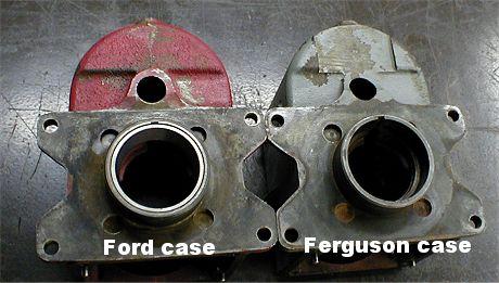
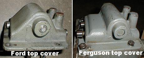
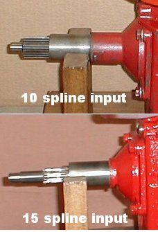
2 There are a few variations on the Sherman combination transmission but the internals are all basically the same. The early models were painted gray and the earliest of those had no retaining set screws for the input shaft bearing. The next generation was painted red but there were no other changes. The third generation had the casting extended on the top cover to completely enclose the shift rails with Welch plugs in the end of the rail bores. They also had a seal added in the top cover to the shifter shaft. These transmissions were for the 9N-2N-8N- NAA and 600 thru 900 series tractors. The fourth generation had the input shaft and nose cone changed to fit the 601 thru 901 series tractors. These tractors used a 15 spline clutch and the earlier tractors used a 10 spline clutch. In the late '50's the last generation of the Shermans was produced by Ford rather than Sherman for the "01" series and the tractors thru These transmissions can be identified by the Ford part numbers cast into them rather than the Sherman part numbers. They were not painted at all. The rear oil slinger was changed to a ribbed type rather than the previous fan type and the shifter forks were cast steel rather than forged. However, all the parts of the latest transmissions were backward compatible so they would interchange directly with the earlier transmissions. The one other Sherman combination available was the model made specifically for the Ferguson TO-20 and TO-30. It was painted a lighter gray, had a modified lower case for clearance of the Ferguson countershaft cap and a modified top cover. The Ford Sherman will NOT fit a Ferguson tractor but the Ferguson model Sherman WILL fit a Ford.
3


4 The Sherman combination being rebuilt in the following photos is a 2nd generation model. It was advertised as being "Very good condition, came from a running tractor, works great".


5 Before disassembly a quick look at the outside reveals major problems with the output shaft. There is serious rust pitting in the back of the output gear. This area is actually the bearing cup or "race" for the front Timken bearing on the tractor's mainshaft. The bearing race surface must be smooth. Installing it like this will mean a growling noise and vibration that will soon destroy the bearing on the tractor's mainshaft. This pitted output shaft is junk and this has quickly become an expensive Sherman rebuild.

 that keep the bearing in place before separating")
6 First we completely disassemble the Sherman. Disassembly is simple and straightforward. Remove 4 bolts and remove the top cover, remove 4 bolts and remove the front input shaft and nose cone, remove the snap ring and take out the rear shaft and gears, drive the lower shaft out the rear of the case and remove the cluster gear. When removing the input shaft from the nose cone be sure to back off the 3 setscrews (shown above) that keep the bearing in place before separating those two pieces. It takes only a few minutes to have the Sherman all apart. Here it's disassembled and ready for a solvent bath.


7 Starting with the main case we find the output shaft bearing race (cup) is badly rusted and needs replaced. The 2 notches on the inside of the case will let you use a punch to knock the old bearing race out. Clean and inspect the case for any cracks or other flaws. All the Sherman combinations have their serial numbers on the front of the case below the countershaft bore. The earliest number we've seen was in the 3000 range and the latest on a Ford case was in the range. This one is serial number


8 The case has been cleaned, inspected, and a new bearing race installed. Next we remove the old bearing and oil slinger from the output shaft.


9 If the rear bearing cup on the output shaft was ok we'd need to check out the rest of the shaft. Diameter #1 is where the step-down gear rides on the shaft. There should be no wear or scoring on this surface. If there is a problem here there will also be a problem in the bore on the step-down gear. Diameter #2 on the splines is where the step-up gear rides on the shaft. Wear here is fairly common and it's not good. A couple of thousandths wear is ok but any more requires a new shaft. Wear here also indicates there is likely a problem in the bore of the stepup gear. The step-up gear can become rippled inside and will also need to be replaced. Diameter #3 is the inside shaft for the needle bearing on the main shaft. It should have no wear or pitting. If it does, the needle bearing won't last long. The new output shaft, slinger and bearing ready to assemble.


10 The bearing cup end of the output shaft should look like this or close to it. Very minor pitting can be acceptable if the pits are small enough that none of them span the length of a roller on the bearing. If there is any pit or flaw big enough that a roller can be affected by it, the bearing will be noisy and will soon fail. That could mean big trouble. Pressing the new bearing onto the shaft. The slinger should be tightly locked under the bearing when you're done.


11 Drop on the rear thrust washer and the output shaft is ready to install. This washer should be " thick. Next, closely inspect the lower cluster gear. All the gear teeth should be in good shape with no abnormal wear. Fortunately, the cluster gear in this transmission is a good one.


12 The needle bearings for the countershaft run directly against the inside bores of the cluster. Inspect the bore on each end for any pitting or damage to the bearing surface. It should be smooth and free of pitting or any other flaws, just like this one. A rough surface here will cause growling noises and will soon destroy the lower bearings. This is an example of a cluster gear that has 3 chipped teeth. It's junk. Chipped teeth on the cluster gear cannot normally be seen just by removing the top cover on the transmission. This is the type of hidden damage you do not want to find when you disassemble your Sherman.


13 The bearing bores in this example cluster gear show some pitting along the length of the needle bearing area and some galling near the inside end. This is not good. Many times when there is wear on the countershaft and/or cluster gear bearing diameters the bearings will come out in pieces. Note the galling on this countershaft front bearing diameter. This shaft is junk.


14 Measure the countershaft at the bearing diameters. It should be smooth and round and should be 1.000" in diameter. If the shaft is otherwise in good shape I will accept a size of.997" but no more than that. If it's worn too much the transmission will be noisy and the bearings will fail. This one is badly worn and measures.984". It's junk. An example of a badly worn countershaft bearing diameter.


15 An example of galling on the rear end of a countershaft bearing diameter. More junk. This needle bearing has rust and pitting on the rollers. The rollers are also starting to crumble on the left end. It's very rare to find any of these that are good enough to use over again. Replace 'em.


16 If the countershaft is good with no excessive wear or pitting it can and should be lightly polished before reinstalling. The countershaft with bearings and thrust washers ready to install.


17 Install the 2 bearings and the center spacer into the cluster gear. Apply a good coating of assembly grease to all parts when installing. "Gluing" the thrust washers to the cluster gear with assembly grease will keep the bearings inside in place while you put the cluster assembly into the case. The small gear goes toward the rear of the case. Note - the front and rear end thrust washers are different. The one with the smaller hole goes on the front end.


18 Be sure to have everything lined up as the countershaft goes in. The last 1/2" or so is a press fit. Once the cluster gear is installed make sure it turns freely and check end play with a feeler gauge. It should be at least.005" and no more than.025". If it has too much end play you need new thrust washers.


19 Next, closely inspect the step-down gear. Make sure there are no chips or abnormal wear on the gear teeth and no wear or rough spots in the bore. Since this gear spins with a metal to metal contact on the output shaft it must be a good fit and have a smooth surface inside the bore. Then check the dentals on the front side where the sliding collar engages with the step-down gear. They should look just like the ones in this photo. Any abnormal wear or damage to the dentals will result in a transmission that jumps out of gear under a load. See the photos below of the sliding collars for examples of abnormal wear on the dentals. Put assembly grease on the output shaft tapered bearing and thrust washer and in the bearing cup on the back of the case. Grease the bore on the step-down gear and place it into the case as shown.


20 Lower the case with the step-down gear down over the output shaft and use a wood block or other suitable item to support the bottom end so it sits flat on the bench as shown. Next is the extremely important inspection of the sliding collars. The sliding collars must be in good shape or the Sherman will not stay in gear. While the two sliding collars may look alike at first glance, they are not alike. Don't mix them up when assembling. The dentals on the collar in this photo are chipped on the ends, probably from someone trying to shift gears without stopping the tractor first. The sides of the dentals still look pretty good. While it's not the best, one like this would probably work ok if you can't locate a better one.


21 The dentals on this collar are badly worn and came from a transmission that would not stay in gear. You can easily see why. This collar is junk along with the step-down gear it mated with. The dentals on the outside of this collar are excellent, just like new. We'll use this one.


22 The rear sliding collar (hi/lo) engages the step-down gear on the outside dentals and engages the step-up gear on the inside of the opposite end. This collar shows badly worn inside splines. It's junk, as is the step-up gear it mated with. A good one looks like this which shows almost no wear and is nearly perfect. We'll use this one.


23 The front sliding collar (direct) has no dental chamfers on the inside splines because it only mates to the front input shaft with the external dentals. A glance at the inside splines will tell you which collar is which. The one on the right is the rear hi/lo collar.


24 The hubs for the sliding collars are also different. The longer hub is for the rear collar and the shorter one is for the front collar. Next we inspect the step-up gear. The dentals should look like these which are in excellent condition. The bore should be smooth and round and be a good fit to the output shaft. This bore is very good but has a couple of tiny rust pits. We will chuck it up in the lathe and polish it lightly with a fine emery paper before installing it.


25 Place the longer hub and the rear sliding collar over the output shaft in the case. Next, install the step-up gear onto the shaft, dentals to the rear. You should be able to slide the collar freely between the step-down and step-up gears and engage either one. Install the front hub and collar and install the snap ring to keep it all in place.


26 Install the brass washer and a new needle bearing and we're ready for the front input (clutch) shaft. The front end of the clutch shaft is supported by the pilot bearing in the flywheel. If the pilot bearing goes bad it can wear the bearing diameter badly on the input shaft and you'll need to replace the input shaft or repair the bearing diameter. This one shows signs that it has spun inside the pilot bearing at some time or other but it has no measurable wear and will be just fine. Check the clutch splines for wear also. The clutch splines on this one look like new.


27 Next, check the seal diameter on the shaft. It should have no measurable grooves or wear. If it does, the seal will never be able to keep the oil in. This one has just a very slight line where the seal rides. It's good. Check the dentals closely on the inside rear of the input shaft gear just like we did for the dentals on the step-down gear. These dentals engage with the front sliding collar for the direct range on the Sherman. Also inspect the bore in the back of the gear. The mainshaft needle bearing rides in this bore and it has to be good. Here we've lightly polished the bore to remove some rust staining.
.")

28 Remove the snap ring and press the old bearing off the input shaft if it needs replaced (they nearly always should be replaced). Press the new bearing on and replace the snap ring. Always use the heavy duty version of the bearing here and not the standard duty. The heavy duty bearing has more balls to carry the heavy radial load from the input shaft.


29 Remove the old seal from the nose cone with an inside puller or a pry bar. Install the new seal with a suitable driver. The seal lip goes toward the inside of the case.


30 Install the input shaft into the front nose cone. Make sure the bearing seats all the way into the pocket. Install the 3 set screws that keep the bearing in place in the nose cone. Inspect them to be sure the cone point is still intact like the one on the right in this photo. If the point is sheared off like the one on the left the set screw needs replaced. The point is the only thing that holds the bearing in place as it protrudes just above the outer bearing race. Do not tighten these set screws more than "snug" as you can distort the bearing race and cause premature bearing failure by over tightening.


31 Put a new gasket on the flange and install the nose cone and input shaft onto the case. That finishes the main Sherman gearbox which brings us to the top shifter cover. The top cover needs to be completely disassembled and checked over closely. Lots of shifting problems are caused by simple problems in the top cover.


32 To disassemble the top cover, remove the 2 tower caps and remove the detent springs and balls. The shift rails should now move freely. Cut the safety wires from the set screws in the forks and remove the set screws. The shifter rails will now come out either end and the forks can be removed. Remove the snap ring on the shifter shaft and pull the shaft out of the shift finger and out of the case. Remove the set screw on the side of the cover and slide the interlock pin out.


33 The disassembled top cover and all the parts. Check the interlock pin. Both ends should be round like half a ball and smooth, not gouged or sheared like the one on the left in this photo. If it's bad, replace it. This pin is what keeps the transmission from going into 2 gears at once. When you shift one rail, the pin slides over and locks the other rail in the neutral position. Lubricate it with some 90w gear lube and install it back in its bore, making sure it slides freely from side to side.


34 The shifter shaft should be polished and checked for straightness. Make sure the Woodruff key slot and the snap ring grooves are good. Check the shift finger for cracks, straightness and excessive wear on the business end. Replace the Woodruff key. The key always wears on the sides and a little bit of wear on the key translates to a lot of play at the end of the shifter lever.

. The lower one is the early style.")
35 Install the shifter shaft, key, shifter finger and snap ring back into the top cover. Make sure the shifter shaft moves freely back and forth and rotates freely side to side. Lube everything with 90w gear lube when assembling. Removing and installing the snap ring is easier with a set of snap ring pliers with a 45 degree bent nose. The two types of shift rails are shown here. On top is the later rail that has a detent for the neutral position (a nice addition). The lower one is the early style. Polish the rails and inspect for straightness and any damage such as rust pitting, scoring or galling. Watch for grooves from the detent ball wearing into the rail.


36 Slide both rails into the top cover and make sure they work freely back and forth and rotate without any binding or tight spots which could indicate a bent rail. Remember the single groove end of the rail is for the interlock pin and the 2 or 3 groove end is installed under the detent ball towers. Inspect the shifter forks for cracks, straightness and wear. The fork above is badly worn. It's junk. Do not try to use something that looks like this one in your Sherman.


37 This is a forged steel fork used in the earlier Shermans. It's in very good condition with only the slightest sign of wear. This is a later style cast steel fork from a Ford built Sherman. They are interchangeable with the early style. This one is also in excellent condition with almost no wear at all.


38 This is the dog point set screw that keeps the shifter fork lined up with the small groove in the center of the shift rail. It's this little guy that causes a lot of shifting problems. Only the shear strength of the dog point on the set screw keeps things aligned and they can shear off as you can see on the one in this photo. Make sure the dog point is good, not worn on the sides or bent or broken. Replace with new ones if there is any doubt. If one of these dog points shears off, the shifter fork will move with the lever but the rail will not and the interlock will effectively block your other gear range until you replace the set screw. The one on the right is good. Place the shifter forks into the cover, slide the rails into the forks, align the center groove in the rail with the set screw holes, and install the set screws finger tight. Turn the set screws until snug then back them off slightly until the fork moves freely side to side without the rail rotating. The fork must be retained to the rail by the dog point only and not by pressure from the screw. Do NOT tighten the set screws with a wrench.


39 Once the set screws are where they belong use safety wire to keep them in place. You should now be able to shift the forks through the 3 different gear positions and everything should move smoothly and easily. Inspect the detent springs for breakage or mushrooming on the ends and replace them if needed. The detent balls get rusty and develop flat spots. Always replace them - they only cost a few cents each. Be sure to lube the detent tower bores and the balls and springs with 90w gear lube when you install them.


40 Everything in the gearbox should have a light coating of assembly lube. Install the new gasket and the top cover. Be sure to get the shifter forks lined up with the grooves in each sliding collar and lower the top cover into place. Leaving the detent caps a little loose will make it easier to shift the transmission while you are bench checking. Don't forget to tighten them when you're done.


41 When the Sherman is installed in the tractor the output shaft is held secure because it's loaded against the tractor transmission main shaft. Do not try to shift the Sherman before it's installed without putting some pressure on the output shaft end. For testing, place the output shaft end of the Sherman down on the workbench so the weight will help keep the output shaft in place when you shift it. In this position you can shift gears and turn the Sherman case around while observing the input shaft. In the high range the input shaft will appear to turn faster than you are turning the case. In low range the input shaft will appear to turn backwards from the direction you're turning the case, and in direct range the input shaft will not move at all while you turn the case. With the output shaft held in place be sure the oil slinger is not rubbing on the case. It can be gently "adjusted" for clearance if necessary.


42 The last item is a new gasket for the mounting plate surface. Make this gasket from 1/64" gasket material. Be sure to check the mounting plate for flatness and for cracked or stripped threads. All finished. Once you've refurbished your Sherman in this manner, have it installed with the correct shims for bearing load, and have it filled with fresh gear oil, you can rest assured it will shift correctly, run smoothly and quietly, and provide reliable service for another 50 years.
43 Bearings used in the Sherman combination transmission - Input shaft bearing - ND 3210 Mainshaft needle bearing - Hyatt Output shaft cup - Timken Output shaft cone - Timken Countershaft bearings - Hyatt Late style top cover shifter shaft seal C/R 6720 Other parts available from New Holland dealers - Front seal 8N7052A Front nose gasket C0NN7C251B Top cover gasket C0NN7223D Shifter fork C0NN7231B Shifter fork setscrew C0NN7B360A Output shaft C3NN7015D Cluster gear C0NN7113B Front countershaft thrust washer C0NN7119A Step-up gear C0NN7A062A Front sliding collar C0NN7A061A Detent spring C0NN7C349A Detent ball Most other parts are no longer available new and must be located used. Best internet source of information and help for old Ford tractors.
MANUAL TRANS OVERHAUL - BORG-WARNER - T56 6-SPEED MANUAL TRANSMISSIONS Borg-Warner T56 (MM6) 6-Speed
 6-Speed") IDENTIFICATION MANUAL TRANS OVERHAUL - BORG-WARNER - T56 6-SPEED 1998 MANUAL TRANSMISSIONS Borg-Warner T56 (MM6) 6-Speed Transmission has 2 identification labels, located on lower left side of case. One
IDENTIFICATION MANUAL TRANS OVERHAUL - BORG-WARNER - T56 6-SPEED 1998 MANUAL TRANSMISSIONS Borg-Warner T56 (MM6) 6-Speed Transmission has 2 identification labels, located on lower left side of case. One
SPECIAL TOOLS Dodge Pickup 5.9L Eng R3500. Fig 1: Identifying Remover C-3985-B (Special Tool) 9/6/13 Printer Friendly View
 9/6/13 Printer Friendly View") Procedures 2003 Dodge Pickup 5.9L Eng R3500 manual transmission SPECIAL TOOLS Fig 1: Identifying Remover C-3985-B (Special Tool) www2.prodemand.com/print/index?content=tabs&module=true&tab=true&terms=true&ymms=false&classname=
Procedures 2003 Dodge Pickup 5.9L Eng R3500 manual transmission SPECIAL TOOLS Fig 1: Identifying Remover C-3985-B (Special Tool) www2.prodemand.com/print/index?content=tabs&module=true&tab=true&terms=true&ymms=false&classname=
SUZUKI SQ 416/420/625 M.Y TRANSMISSION SERVICE MANUAL - MANUAL - AUTOMATIC - TRANSFER - DIFFERENTIALS
 SUZUKI SQ 416/420/625 M.Y 1998-2005 TRANSMISSION SERVICE MANUAL - MANUAL - AUTOMATIC - TRANSFER - DIFFERENTIALS WARNING/CAUTION/NOTE IMPORTANT Please read this manual and follow its instructions carefully.
Transmission Overhaul Procedures-Bench Service
 How to Assemble the Lower Reverse Idler Gear Assembly Special Instructions In 1996 Eaton changed the reverse idler system design. In the nut design, the reverse idler bearing was lubricated through a hole
TRANSMISSION 6.7 GENERAL HOME. See Figure The transmission is a five-speed constantmesh type housed in an extension of the crankcase.
 TRANSMISSION 6.7 GENERAL See Figure 6-45. The transmission is a five-speed constantmesh type housed in an extension of the crankcase. Mainshaft Neutral Mainshaft st Gear b06x6x Countershaft 4 Out 5 Countershaft
SECTION 5B MANUAL TRANSMISSION TABLE OF CONTENTS
 SECTION 5B MANUAL TRANSMISSION TABLE OF CONTENTS General Description and Operation... 5B-2 Shift Lever... 5B-2 Transmission Assembly... 5B-2 Specifications... 5B-3 Diagnostic Information and Procedures...
STERNDRIVE UNIT 3 B GEAR HOUSINGS MR/ALPHA ONE/ALPHA ONE SS
 STERNDRIVE UNIT 3 B 23146 GEAR HOUSINGS MR/ALPHA ONE/ALPHA ONE SS Table of Contents Page Identification........................... 3B-1 Specifications.......................... 3B-1 Torque Specifications................
*Some speedometers have these additional electronic connections. If yours does, then remove the smaller slotted screws shown.
 www.odometergears.com 1981-1985 240 Cable-Driven Speedometers (NOT for 1986 and later electronic units) http://www.davebarton.com/240-odometer-repair.html For this set of instructions below, I will not
DISASSEMBLY. Transmission. 2. Remove the 4 clutch housing bolts. Separate the clutch housing from the transmission.
 308-03A-1 DISASSEMBLY Transmission 308-03A-1 Special Tool(s) Puller, Bearing 205-D064 (D84L-1123-A) or equivalent Remover/Installer, Front Wheel Hub 204-069 (T81P-1104-C) 2. Remove the 4 clutch housing
TRANSMISSION AND TRANSFER CASE
 TJ TRANSMISSION AND TRANSFER CASE 21-1 TRANSMISSION AND TRANSFER CASE TABLE OF CONTENTS page MANUAL TRANSMISSION - NSG370...1 AUTOMATIC TRANSMISSION - 42RLE...37 page TRANSFER CASE - NV231...165 TRANSFER
TRANSMISSION 6.7 GENERAL HOME. See Figure The transmission is a five-speed constantmesh type housed in an extension of the crankcase.
 TRANSMISSION 6.7 GENERAL See Figure 6-46. The transmission is a five-speed constantmesh type housed in an extension of the crankcase. b06x6x Neutral st Gear Mainshaft Mainshaft 4 5 4 5 Countershaft Out
Transmission Overhaul Procedures-Bench Service
 How to Install the Auxiliary Countershaft Assembly Special Instructions To make auxiliary section assembly easier, you can make an auxiliary section fixture out of a 2" x 12" piece of wood. 3' 1' 3" 4.56"
TRANSMISSION AND TRANSFER CASE
 DR TRANSMISSION AND TRANSFER CASE 21-1 TRANSMISSION AND TRANSFER CASE TABLE OF CONTENTS page MANUAL TRANSMISSION- G56- SERVICE INFORMATION...1 MANUAL TRANSMISSION- GETRAG 238- SERVICEINFORMATION...69 MANUAL
MANUAL TRANSMISSION MUA 5C (4X2, 4X4) AND TREMEC T5R(4X2)
 AND TREMEC T5R(4X2)") MANUAL TRANSMISSION 7B 1 RODEO TRANSMISSION MANUAL TRANSMISSION MUA 5C (4X2, 4X4) AND TREMEC T5R(4X2) CONTENTS Service Precaution...................... 7B 2 General Description..................... 7B
MANUAL TRANSMISSION 7B 1 RODEO TRANSMISSION MANUAL TRANSMISSION MUA 5C (4X2, 4X4) AND TREMEC T5R(4X2) CONTENTS Service Precaution...................... 7B 2 General Description..................... 7B
Gearbox Assembly 101. Introduction. Before Beginning. By Mark Schutzer 4/13/06
 Gearbox Assembly 101 By Mark Schutzer 4/13/06 Introduction If you are planning to re-motor an old brass locomotive you may want to upgrade to a new gearbox at the same time. The early 60 s and 70 s gearboxes
MANUAL TRANSMISSION SERVICE
 MANUAL TRANSMISSION SERVICE Introduction Internal combustion engines develop very little torque or power at low rpm. This is especially obvious when you try to start out in direct drive, 4th gear in a
Service Manual. Fuller Mechanical Transmissions TRSM0992 October 2007
 Service Manual Fuller Mechanical Transmissions TRSM0992 October 2007 Introduction Warnings and Precautions Before starting a vehicle always be seated in the driver s seat, place the transmission in neutral,
TRANSMISSION AND TRANSFER CASE
 XJ TRANSMISSION AND TRANSFER CASE 21-1 TRANSMISSION AND TRANSFER CASE TABLE OF CONTENTS page AX5 MANUAL TRANSMISSION... 1 NV3550 MANUAL TRANSMISSION... 42 AUTOMATIC TRANSMISSION 30RH... 88 page AW 4 AUTOMATIC
G.A.S. M54 DISA Repair Kit D.I.Y. Instructions
 Home BMW Solutions Porsche Solutions DIY Tech Engine Services Dyno Services Machining About G.A.S. Contact G.A.S. M54 DISA Repair Kit D.I.Y. Instructions The installation of the German Auto Solutions DISA
CROWERGLIDE AUTOMATIC CLUTCH Instruction Manual
 CROWERGLIDE AUTOMATIC CLUTCH Instruction Manual Crower Cams & Equipment Co., Inc 6180 Business Center Court San Diego, CA. 92154 Phone: 619.661.6477 ext. 148 Fax: 619.690.7846 www.crower.com TABLE OF CONTENTS
Installation Instructions
 Instructions Created by an: 86-95 Suzuki Samurai Samurai Complete Transmission Rebuild Kit with Synchronizers (SKU# STM-RP) Installation Instructions Part I Notice: If there are any parts you need that
2001 Dodge RAM 3500 PICKUP
 1 of 76 9/14/2012 7:02 PM 2001 Dodge RAM 3500 PICKUP Submodel: Engine Type: L6 Liters: 5.9 Fuel Delivery: FI Fuel: DIESEL Subarticles MANUAL- NV3500 - DISASSEMBLY MANUAL- NV3500 - DISASSEMBLY MANUAL -
Service Manual Blue Giant
 R 2000 Service Manual Blue Giant Models PT-50 and PT-55 Developed by Super Stores Service This manual is intended for basic service and maintenance of the Blue Giant pallet jack. The pallet jacks you are
Maintenance Information
 Form 16575334 Edition 1 April 2005 Electric Screwdrivers EL, EP and ET 34V DC Series Maintenance Information Save These Instructions WARNING Maintenance procedures have the potential for severe shock hazard
$1.00 FOR THE TQIO/RCIO
 $1.00 FOR THE TQIO/RCIO m mm HDBBYSHOP Champion Jay Halsey has an impressive track record. One of Jay's advantages is a whisper smooth tranny thanks to his dad, Jim. Now you can build a Halsey transmission!
 www.odometergears.com Mercedes-Benz Mechanical Odometer Repair This how to can be used for all mechanical repairs as the only difference will be the removal of the instrument cluster. http://www.dieselgiant.com/repairyourodometer.htm
1967 (Late) CORVETTE STANDARD (NON-ADJUSTABLE) STEERING COLUMN DISASSEMBLY & REPAIR INSTRUCTIONS PAPER #2
 CORVETTE STANDARD (NON-ADJUSTABLE) STEERING COLUMN DISASSEMBLY & REPAIR INSTRUCTIONS PAPER #2") Last Revision: 03SE2012 1967 (Late) - 1968 CORVETTE STANDARD (NON-ADJUSTABLE) STEERING COLUMN DISASSEMBLY & REPAIR INSTRUCTIONS PAPER #2 Disassembly and Repair Instructions Addressed in this Paper Degree
Last Revision: 03SE2012 1967 (Late) - 1968 CORVETTE STANDARD (NON-ADJUSTABLE) STEERING COLUMN DISASSEMBLY & REPAIR INSTRUCTIONS PAPER #2 Disassembly and Repair Instructions Addressed in this Paper Degree
15.Main Shaft Assembly
 15.Main Shaft Assembly A: REMOVAL 1) Remove the manual transmission assembly from vehicle. 2) Remove the transfer case with extension case assembly.
DRIVE AXLE Volvo 960 DESCRIPTION & OPERATION AXLE IDENTIFICATION DRIVE AXLES Volvo Differentials & Axle Shafts
 DRIVE AXLE 1994 Volvo 960 1994 DRIVE AXLES Volvo Differentials & Axle Shafts 960 DESCRIPTION & OPERATION All 960 station wagon models use type 1041 rear axle assembly. All 960 4-door models use type 1045
MANUAL TRANSAXLE Return to Main Table of Contents
 MANUAL TRANSAXLE Return to Main Table of Contents GENERAL... 2 MANUAL TRANSAXLE CONTROL... 12 SHIFT LEVER ASSEMBLY... 14 MANUAL TRANSAXLE... 15 MANUAL TRANSAXLE ASSEMBLY... 17 FIFTH SPEED SYNCHRONIZER
CHAPTER 7 TRANSMISSION (MFO6S)
") 1 page INDEX1 Model SG1J (MF06S) TRANSMISSION 7-1 7-142E-07 CHAPTER 7 TRANSMISSION (MFO6S) Model SG1J 1 Models FE, FF and SG2J 1 Model FD 7 TROUBLESHOOTING...7-2 SPECIAL TOOLS...7-5 REMOVAL...7-7 GEAR
1 page INDEX1 Model SG1J (MF06S) TRANSMISSION 7-1 7-142E-07 CHAPTER 7 TRANSMISSION (MFO6S) Model SG1J 1 Models FE, FF and SG2J 1 Model FD 7 TROUBLESHOOTING...7-2 SPECIAL TOOLS...7-5 REMOVAL...7-7 GEAR
REPAIR MANUAL URW SERIES. URW-6, 8, 9, 10 & 12 Series Repair Manual
 REPAIR MANUAL URW SERIES URW-6, 8, 9, 10 & 12 Series Repair Manual Contents Page 1. Tools Needed for Repair 1 2. Disassembly and Reassembly of the Cam Casing 2-4 3. Disassembly and Reassembly of the Gear
 a. SCOPE. g. : RA PD 28742 TM 9;1803B 2. MWO AND MAJOR UNIT ASSEMBLY REPLACEMENT RECORD. a. Description. b. _Instructions for Use. Early Modifications. CHAPTER 2 Section I 3. POWER TRAIN DESCRIPTION. a.
DRIVE AXLE Nissan 240SX DESCRIPTION & OPERATION AXLE RATIO & IDENTIFICATION AXLE SHAFT & BEARING R & I DRIVE SHAFT R & I
 DRIVE AXLE 1990 Nissan 240SX 1990 DRIVE AXLES Rear Axle - R200 240SX, 300ZX DESCRIPTION & OPERATION The axle assembly is a hypoid type gear with integral carrier housing. The pinion bearing preload adjustment
Diagnostic Procedures
 Section 6 Diagnostic Procedures Learning Objectives: 1. Describe manual transmission, transaxle and transfer case component inspection and diagnostic procedures 2. Identify clutch component inspection
Installation Instructions for the Tera low range Dana 20 (LOW20)
") Installation Instructions for the Tera low range Dana 20 (LOW20) Tera Manufacturing, Inc. 5251 South Commerce Dr. Murray, Utah 84107 Phone/801.288.2585 Fax/801.288.2571 www.teraflex.biz Attention: Verify
Installation Instructions for the Tera low range Dana 20 (LOW20) Tera Manufacturing, Inc. 5251 South Commerce Dr. Murray, Utah 84107 Phone/801.288.2585 Fax/801.288.2571 www.teraflex.biz Attention: Verify
MANUAL TRANSAXLE SECTIONMT CONTENTS IDX. Shift Control Components...34
 MANUAL TRANSAXLE SECTIONMT GI MA EM LC EC CONTENTS FE PREPARATION...3 Special Service Tools...3 Commercial Service Tools...5 NOISE, VIBRATION AND HARSHNESS (NVH) TROUBLESHOOTING...6 NVH Troubleshooting
ASSEMBLY. Transmission Automatic Transmission 5R44E and 5R55E. Special Tool(s)
") 307-01-1 Automatic Transmission 5R44E and 5R55E 307-01-1 ASSEMBLY Transmission Special Tool(s) Holding Fixture, Transmission 307-262 (T93T-77002-AH) Special Tool(s) Installer, Transmission Extension Housing
307-01-1 Automatic Transmission 5R44E and 5R55E 307-01-1 ASSEMBLY Transmission Special Tool(s) Holding Fixture, Transmission 307-262 (T93T-77002-AH) Special Tool(s) Installer, Transmission Extension Housing
Another CJ picture guide to replacing the key cylinder in a non-tilt steering column
 Another CJ picture guide to replacing the key cylinder in a non-tilt steering column by John Strenk Well I'm sure it's happened to all of us one time or another. You park your jeep and go to turn off your
Mikuni RS Carburetor Conversion
 Mikuni RS Carburetor Conversion After putting your carbies on the bench or the kitchen table if the wife is out, you will see that the linkages may be in different positions depending on which brand of
MANUAL TRANSMISSION SECTION MT CONTENTS TRANSMISSION/TRANSAXLE MT-1 SERVICE INFORMATION POSITION SWITCH...13 Checking...13
 TRANSMISSION/TRANSAXLE SECTION MT A B MANUAL TRANSMISSION MT D CONTENTS E SERVICE INFORMATION... 2 PRECAUTIONS... 2 Service Notice or Precaution...2 PREPARATION... 3 Special Service Tool...3 Commercial
Another CJ picture guide to
 Another CJ picture guide to replacing the key cylinder in a non-tilt steering column by John Strenk Well I'm sure it's happened to all of us one time or another. You park your jeep and go to turn off your
SECTION TF CONTENTS TRANSFER IDX
 TRANSFER SECTION TF GI MA EM LC PREPARATION...2 Special Service Tools...2 Commercial Service Tools...3 NOISE, VIBRATION AND HARSHNESS (NVH) TROUBLESHOOTING...4 NVH Troubleshooting Chart...4 Transfer...4
TRANSFER SECTIONTF CONTENTS IDX EXIT. Counter Gear...20
 TRANSFER SECTIONTF GI MA EM LC EC CONTENTS FE CL PREPARATION...2 Special Service Tools...2 Commercial Service Tools...3 NOISE, VIBRATION AND HARSHNESS (NVH) TROUBLESHOOTING...5 NVH Troubleshooting Chart...5
PROPELLER SHAFT & DIFFERENTIAL CARRIER SECTIONPD CONTENTS
 PROPELLER SHAFT & DIFFERENTIAL CARRIER SECTIONPD CONTENTS PREPARATION...2 PROPELLER SHAFT...5 On-Vehicle Service...6 Removal and Installation...7 Inspection...7 Disassembly...7 Assembly...8 ON-VEHICLE
TRANSFER SECTIONTF CONTENTS IDX
 TRANSFER SECTIONTF GI MA EM LC EC CONTENTS FE PREPARATION...2 Special Service Tools...2 Commercial Service Tools...3 NOISE, VIBRATION AND HARSHNESS (NVH) TROUBLESHOOTING...5 NVH Troubleshooting Chart...5
Maintenance Information
 80234313 Edition 1 June 2006 Air Grinder, Die Grinder, Sander and Belt Sander Series G1 (Angle) Maintenance Information Save These Instructions WARNING Always wear eye protection when operating or performing
Assembly Manual. 1/10th Formula 1 Car
 Assembly Manual 1/10th Formula 1 Car Center Pivot Bag 1 3374 - Center Pivot Socket 40194 - Hard Anodized Alum Pivot ball 3254-2-56 *Note - Sometimes it is helpful to slightly over-tighten the top clamp
Maintenance Information
 16575219 Edition 4 October 2013 Air Screwdrivers QP1P, QP1S and QP1T Series Maintenance Information Save These Instructions Product Safety Information WARNING Failure to observe the following warnings,
 Page 1 of 15 Transmission, Model S5-42 ZF Model S5-42 ZF Disassembly NOTE: For 4x4 and F-Super Duty vehicles, skip to Step 5. 1. Attach the transmission to the Bench Mounted Holding Fixture T57L-500-B
InstalL Instructions. trail-creeper 4.70 transfer case gear kit ( KIT and KIT) kit contents
 kit contents") InstalL Instructions trail-creeper 4.70 transfer case gear kit (105000-1-KIT and 105001-1-KIT) kit contents 5356 PINE AVE FRESNO, CA 93727 USA TOLL FREE: 877.4X4.TOYS WORLDWIDE: 559.252.4950 WWW.TRAIL-GEAR.COM
InstalL Instructions trail-creeper 4.70 transfer case gear kit (105000-1-KIT and 105001-1-KIT) kit contents 5356 PINE AVE FRESNO, CA 93727 USA TOLL FREE: 877.4X4.TOYS WORLDWIDE: 559.252.4950 WWW.TRAIL-GEAR.COM
Change Your Tail Wheel Bearings (and Races)
") Change Your Tail Wheel Bearings (and Races) Note: You must have the approval of a certified aircraft mechanic (A&P) to perform this procedure. This procedure worked with my tail wheel but yours may differ.
Change Your Tail Wheel Bearings (and Races) Note: You must have the approval of a certified aircraft mechanic (A&P) to perform this procedure. This procedure worked with my tail wheel but yours may differ.
Installation Instructions
 Instructions Created by an: Inchworm Gear Clockable Toyota Dual Transfer Case Adapter Kit, 21 or 23 Spline SKU# TCASE-IW-300-000 Installation Instructions CAUTION: Safety glasses should be worn at all
Prerequisites: Shop Manual (recommended) pages 3-9 through 3-13.
 pages 3-9 through 3-13.") Prerequisites: Order your gaskets average about $25.00 bucks X 2 so $50.00 4NK-11193-00-00 Obtain a shim kit (Should have several 265 and 270s) (Some dealers will exchange) Obtain a Valve Bucket Tool YM-33961
Prerequisites: Order your gaskets average about $25.00 bucks X 2 so $50.00 4NK-11193-00-00 Obtain a shim kit (Should have several 265 and 270s) (Some dealers will exchange) Obtain a Valve Bucket Tool YM-33961
TSM54/52 MANUAL TRANSMISSION
 3B-1 SECTION 00 3B TSM54/52 MANUAL TRANSMISSION Table of Contents GENERAL INFORMATION... 3B-3 Overview... 3B-3 Specifications... 3B-4 System components... 3B-5 Shifting mechanism... 3B-17 Diagnostic information
COLT 2310, 2510, AND 2712 COM PACT TRACTORS CHAPTER 7 BEARINGS, SEALS, GASKETS
 COLT 2310, 2510, AND 2712 COM PACT TRACTORS CHAPTER 7 BEARINGS, SEALS, GASKETS END PLAY SEE SPECIFICATIONS "A" SHIM C" GASKET "B" STEEL WASHER IF REQUIRED 7-A-l Figure 7-A-l illustrates the correct assembly
Parts made by people who race and know what it is about
 RACING TRANSMISSIONS / 840 SERIES The 840 series has been one of the best options for front engine-rear wheel drive racing cars with4/6 cylinder engines since 1975; formerly, with the TC models, and at
HORSTMAN GREASED LIGHTNING CLUTCH
 HORSTMAN GREASED LIGHTNING CLUTCH Horstman s Greased Lightning (GL) clutch is designed for ultra high performance, and requires expert setup and a serious commitment to maintenance. Warning!!! 1. Clutch
1967 (Late) and 1968 CORVETTE TELESCOPING STEERING COLUMN DISASSEMBLY & REPAIR INSTRUCTIONS - PAPER #1
 and 1968 CORVETTE TELESCOPING STEERING COLUMN DISASSEMBLY & REPAIR INSTRUCTIONS - PAPER #1") Last Revision: 03SE2012 1967 (Late) and 1968 CORVETTE TELESCOPING STEERING COLUMN DISASSEMBLY & REPAIR INSTRUCTIONS - PAPER #1 Disassembly and Repair Instructions Addressed in this Paper Difficulty Page
Last Revision: 03SE2012 1967 (Late) and 1968 CORVETTE TELESCOPING STEERING COLUMN DISASSEMBLY & REPAIR INSTRUCTIONS - PAPER #1 Disassembly and Repair Instructions Addressed in this Paper Difficulty Page
INSTRUCTIONS. Disassembly. Shifter Cam Assembly. Shifter Forks
 INSTRUCTIONS Disassembly To protect against accidental start-up of vehicle, always disconnect the negative battery cable before working on the motorcycle. Failure to disconnect the battery cable could
TRANSFER CASE Mitsubishi Montero APPLICATION DESCRIPTION TESTING 4WD INDICATOR CONTROL UNIT (MONTERO) DETECTION SWITCH
 DETECTION SWITCH") TRANSFER CASE 1993 Mitsubishi Montero 1991-94 TRANSFER CASES Mitsubishi Dodge; Ram-50 Mitsubishi; Pickup, Montero APPLICATION TRANSFER CASE APPLICATIONS TABLE Application (1) Transmission Model Dodge 1991-93
TRANSFER CASE 1993 Mitsubishi Montero 1991-94 TRANSFER CASES Mitsubishi Dodge; Ram-50 Mitsubishi; Pickup, Montero APPLICATION TRANSFER CASE APPLICATIONS TABLE Application (1) Transmission Model Dodge 1991-93
STERNDRIVE UNIT 3 A DRIVE SHAFT HOUSING
 STERNDRIVE UNIT 3 A 23262 DRIVE SHAFT HOUSING Table of Contents Page Specifications............................ 3A-1 Torque Specifications.................. 3A-1 Upper Drive Shaft Bearing Preload.......
GEARBOX AND 4X4 COUPLING UNIT SERVICE TOOLS SERVICE TOOLS OTHER SUPPLIER SERVICE PRODUCTS
 GEARBOX AND 4X4 COUPLING UNIT SERVICE TOOLS Description Part Number Page BLIND HOLE BEARING PULLER SET... 529 036 117... 199 COUNTERSHAFT OIL SEAL PUSHER... 529 036 222... 192 ECM ADAPTER TOOL... 529 036
Maintenance Information
 04581245 Edition 2 May 2014 Air Grinder, Die Grinder and Sander Series G2 (Angle) Maintenance Information Save These Instructions Product Safety Information WARNING Failure to observe the following warnings,
DESCRIPTION AND OPERATION. Description
 file://c:\tso\tsocache\vdtom_5368\svk~us~en~file=svk73001.htm~gen~ref.htm Page 1 of 1 Section 07-03: Transmission, Manual, M5OD DESCRIPTION AND OPERATION 1997 Ranger Workshop Manual Description The M5OD
Maintenance Information
 80234313 Edition 2 May 2014 Air Grinder, Die Grinder, Sander and Belt Sander Series G1 (Angle) Maintenance Information Save These Instructions Product Safety Information WARNING Failure to observe the
Timing the 9N/2N Steering Sector Gears
 Timing the 9N/2N Steering Sector Gears by John Korschot - www.johnsoldiron.com (May 2010) The procedure for timing a set of steering gears in the 9/2n tractors is published in the I&T FO4 shop manual.
UOW Series Repair Manual UOW-11 & UOW-T60 Series
 UOW Series Repair Manual UOW-11 & UOW-T60 Series 100000 SE Pine St., Portland, OR 97216 800-852-1368 503-254-6600 www.aimco-global.com Contents Page 1. Tools Needed for Repair 2 2. Disassembly and Reassembly
Our goal is to make the install a breeze. Please read the entire guide before beginning.
 www.airkewld.com Page 1 of 6 IRS Axle Kit Install IRS Axle Kit Install Our goal is to make the install a breeze. Please read the entire guide before beginning. KITS SHOULD INCLUDE 2 - Control-arm mounting
MANUAL TRANSMISSION SECTIONMT CONTENTS IDX FS5W71C. Case Components...27
 MANUAL TRANSMISSION SECTIONMT GI MA EM LC EC CONTENTS FE FS5W71C PREPARATION...3 Special Service Tools...3 Commercial Service Tools...5 NOISE, VIBRATION AND HARSHNESS (NVH) TROUBLESHOOTING...6 NVH Troubleshooting
Suzuki Samurai 6.5 Transfer Case Gear Kit, KIT
 Suzuki Samurai 6.5 Transfer Case Gear Kit, 105004-3-KIT Kit Contents: Gear, 26 Spline/26 Tooth 1.0 Gear, 44 Tooth 1.0 Gear, 58 Tooth/23 Tooth 1.0 Gear, 67 Tooth/ 27 Tooth 1.0 Counter Shaft 1.0 Counter
POWER STEERING PUMP REBUILDING SPK101 Read instructions completely before removal & disassembly
 POWER STEERING PUMP REBUILDING SPK101 Read instructions completely before removal & disassembly DISASSEMBLY: 1. Remove pump from car and allow to drain. 2. Remove pulley from front of pump. This requires
INSTALLATION MANUAL. TORQ Locker TL GM 14 Bolt Installation Instructions. Made in USA By: Page 1 of 8
 INSTALLATION MANUAL TORQ Locker TL-19035 GM 14 Bolt Installation Instructions Made in USA By: Page 1 of 8 Page 2 of 8 INSTALLATION MANUAL TORQ Locker TL-19035 GM 14 Bolt Installation Instructions By: INTRODUCTION
Bag 1. Bag 1. Center Pivot. Center Pivot
 8 00734 01901 5 Center Pivot Bag 1 3374 - Center Pivot Socket 4019 - Alum Pivot ball 3254-2-56 Button Head *Note - Sometimes it is helpful to slightly over-tighten the top clamp screws, then work the ball
NP231 SHORT SHAFT "FIXED YOKE" KIT
 Page 1 of 11 KIT CONSISTS OF: No. Qty Part No. Description 1. 1 51-7905 TAILHOUSING, DIECAST 2. 1 52-7905 SHAFT, MAIN OUTPUT 3. 1 300474 SEAL WASHER, REAR YOKE 4 1 300475 YOKE, C.V. REAR 5. 1 300476 NUT,
MANUAL TRANSMISSION SECTIONMT CONTENTS IDX FS5W71C. ASSEMBLY...24 Gear Components...24
 MANUAL TRANSMISSION SECTIONMT GI MA EM LC EC CONTENTS FE FS5W71C PREPARATION...3 Special Service Tools...3 Commercial Service Tools...5 NOISE, VIBRATION AND HARSHNESS (NVH) TROUBLESHOOTING...6 NVH Troubleshooting
20.Driven Gear Assembly
 20.Driven Gear Assembly A: REMOVAL 1) Remove the manual transmission assembly from vehicle. 2) Prepare the transmission for overhaul.
ADVANCE ADAPTERS INC. Fixed Yoke kit (S.Y.E. Kit)
") ADVANCE ADAPTERS INC. Fixed Yoke kit (S.Y.E. Kit) Instruction Sheet P/N: 50-7905 & 50-7906 KIT CONSISTS OF: No. Qty Part No. Description 1. 1 51-7906 TAILHOUSING, DIECAST 2. 1 52-7905 SHAFT, MAIN OUTPUT
ADVANCE ADAPTERS INC. Fixed Yoke kit (S.Y.E. Kit) Instruction Sheet P/N: 50-7905 & 50-7906 KIT CONSISTS OF: No. Qty Part No. Description 1. 1 51-7906 TAILHOUSING, DIECAST 2. 1 52-7905 SHAFT, MAIN OUTPUT
Maintenance Information
 16572679 Edition 2 May 2014 Air Drill QP Series Maintenance Information Save These Instructions Product Safety Information WARNING Failure to observe the following warnings, and to avoid these potentially
Building a Bulletproof NP205 Tips and tricks for the toughest transfer case available. Photography by Rick Péwé 4Wheel & Off-Road, February, 2009
 Building a Bulletproof NP205 Tips and tricks for the toughest transfer case available. Photography by Rick Péwé 4Wheel & Off-Road, February, 2009 The venerable NP205 transfer case has a reputation for
LoMax 205 CASE & 3:1 GEAR SET. Manufactured by JB CONVERSIONS, INC. Phone: Installation Instructions for the GM NP205 Transfer Case
 LoMax 205 CASE & 3:1 GEAR SET Part No. 2800 Instruction Rev: 2007.08.16 Manufactured by JB CONVERSIONS, INC. Phone: Installation Instructions for the GM NP205 Transfer Case Kit Components: 1. (1) 42x25
1. General Description
 1. General Description A: SPECIFICATION 1. MANUAL TRANSMISSION AND FRONT DIFFERENTIAL Type Transmission gear ratio Front reduction gear Rear reduction gear Front differential Center differential Final
Maintenance Information
 Form 16573321 Edition 1 July 2004 Air Grinder Series 61H Maintenance Information Save These Instructions Always wear eye protection when operating or performing maintenance on this tool. Always turn off
Amarillo PUMP DRIVES (250 HP THROUGH 350 HP) INSTRUCTIONS FOR REPAIRING MODELS 250, 300, and 350
 INSTRUCTIONS FOR REPAIRING MODELS 250, 300, and 350") Amarillo PUMP DRIVES (250 HP THROUGH 350 HP) INSTRUCTIONS FOR REPAIRING MODELS 250, 300, and 350 Amarillo Right Angle Pump Drives, if properly installed and maintained, should provide years of service
Amarillo PUMP DRIVES (250 HP THROUGH 350 HP) INSTRUCTIONS FOR REPAIRING MODELS 250, 300, and 350 Amarillo Right Angle Pump Drives, if properly installed and maintained, should provide years of service
SECTION A DISASSEMBLY AND INSPECTION OF THE OIL PUMP
 This is an old draft of some TH400 oil pump technical information. Diagrams supplied by General Motors and ATSG have been noted and are the property of the credited entity. SECTION A DISASSEMBLY AND INSPECTION
Maintenance Instructions
 General Note These instructions contain information common to more than one model of Bevel Gear Drive. To simplify reading, similar models have been grouped as follows: GROUP 1 Models 11, 0, 1,, (illustrated),,
INSTRUCTIONS & RECOMMENDATIONS
 INSTRUCTIONS & RECOMMENDATIONS Oil We recommend the equivalent of 90-weight gear oil. Synthetic is acceptable and additives are optional. Lighter oils are not recommended, but if used, gears should be
CHAPTER 11: FLYWHEEL, CLUTCH AND ALTERNATOR BACK ON
 CHAPTER 11: FLYWHEEL, CLUTCH AND ALTERNATOR BACK ON Posted on the Wildguzzi forum by Pete Roper: January 17, 2006: Contents: Assembling the engine. Flywheel, clutch and alternator back on. Pic 11-1: To
3.2 DRIVE TORQUE HUB. Roll, Leak and Brake Testing SECTION 3 - CHASSIS & TURNTABLE. 3-2 JLG Lift
 3.2 DRIVE TORQUE HUB Roll, Leak and Brake Testing 10 LUG PATTERN Torque-Hub units should always be roll and leak tested before disassembly and after assembly to make sure that the unit's gears, bearings
DrVanos.com Stage II Installation Instructions. Tool rental is available with the purchase of a vanos kit *See website for more info*
 DrVanos.com Stage II Installation Instructions Special Tools Needed: Camshaft locking tool TDC Crank pin Sprocket turning tool Tool rental is available with the purchase of a vanos kit *See website for
Ford 9 XD Aussie-Locker Install Instructions.
 Ford 9 XD-45831 Aussie-Locker Install Instructions. Before the install check the following. 1. Must be 31 spline 4-pinion carrier. 2. Must be an open carrier not a limited slip. 3. Refer to Ford or vehicle
LT230T TRANSFER GEARBOX. Overhaul Manual LT230T. Verdeelbak revisieboek LT230T. Boîte de transfert Manuel de révision LT230T
 LT230T TRANSFER GEARBOX Overhaul Manual LT230T Verdeelbak revisieboek LT230T Boîte de transfert Manuel de révision LT230T Verteilergetriebe Überholungsanleitung LT230T Riduttore Manuale di revisione LT230T
ADVANCE ADAPTERS INC. P/N: NP231 SHORT SHAFT "FIXED YOKE" KIT
 Paso Robles, CA 93447 PAGE 1 OF 10 Telephone: (800) 350-2223 Fax: (805) 238-4201 Page Rev. Date: 06-24-02 KIT CONSISTS OF: No. Qty Part No. Description 1. 1 51-7906 TAILHOUSING, DIECAST 2. 1 52-7905 SHAFT,
Porsche 928 with 16v LH-Jetronic Fuel System
 Porsche 928 with 16v LH-Jetronic Fuel System Toll-Free Tech Hot Line: 877-FOR-928M 877-367-9286 Please do not copy this manual and give copies to your friends. Our ability to bring you this supercharger
Assembly Manual. 1/10th World GT car
 Assembly Manual 1/10th World GT car Center Pivot Bag 1 3374 - Center Pivot Socket 40194 - Hard Anodized Alum Pivot ball 3254-2-56 Button Head *Note - Sometimes it is helpful to slightly over-tighten the
1988 Chevrolet Pickup V SUSPENSION - FRONT (4WD)' 'Front Suspension - "V" Series 1988 SUSPENSION - FRONT (4WD) Front Suspension - "V" Series
' 'Front Suspension - V Series 1988 SUSPENSION - FRONT (4WD) Front Suspension - V Series") 1988 SUSPENSION - FRONT (4WD) Front Suspension - "V" Series DESCRIPTION NOTE: Vehicle serial numbers used in this article has been abbreviated for common reference to Chevrolet and GMC models. Chevrolet
1988 SUSPENSION - FRONT (4WD) Front Suspension - "V" Series DESCRIPTION NOTE: Vehicle serial numbers used in this article has been abbreviated for common reference to Chevrolet and GMC models. Chevrolet
SECTION B Manual Transaxle/Transmission TR6060
 308-03B-i Manual Transaxle/Transmission TR6060 308-03B-i SECTION 308-03B Manual Transaxle/Transmission TR6060 CONTENTS PAGE Transmission... 308-03B-2 308-03B-2 Manual Transaxle/Transmission TR6060 308-03B-2
Installation Instructions Street Bandit Shifter
 Installation Instructions Street Bandit Shifter Part Number 80797 (see www.bmracing.com for the latest technical product information) 2006, 2000 by B&M Racing and Performance Products The B&M Street Bandit
13. CRANKCASE/CRANKSHAFT/BALANCER/PISTON/CYLINDER
 13. CRANKCASE/CRANKSHAFT/BALANCER/PISTON/CYLINDER COMPONENT LOCATION 13-2 SERVICE INFORMATION 13-3 TROUBLESHOOTING 13-4 CRANKCASE SEPARATION 13-5 CRANKSHAFT 13-7 MAIN JOURNAL BEARING 13-9 CRANKPIN BEARING
Maintenance Information
 45528270 Edition 1 June 2007 Barring Motor T480 Series Maintenance Information Save These Instructions WARNING Always wear eye protection when operating or performing maintenance on this Barring Motor.