ALWAYS follow all Webasto installation and repair instructions and observe all warnings.
|
|
|
- Frank Snow
- 6 years ago
- Views:
Transcription
1 Water Heater Unit Feel the drive Thermo Top C Additional Heater e Installation Instructions Chevrolet Captiva Diesel from Model Year 007 Left-hand drive vehicle Automatic transmission WARNING! Hazard warning: Incorrect installation or repair of Webasto heating systems may cause a fire or result in the emission of carbon monoxide, which can be fatal. Serious or fatal injuries can be caused as a result. Specialist company training, technical documentation, specialized tools and equipment are required to install and repair Webasto heating and cooling systems. NEVER attempt to install or repair Webasto heating or cooling systems if you have not successfully completed the company training and thereby acquired the required technical skills, or if you do not have access to the required technical documentation, tools and equipment needed to carry out correct installation and repairs. ALWAYS follow all Webasto installation and repair instructions and observe all warnings. Webasto does not accept any liability for defects and damage that are attributable to installation by untrained staff. Ident. No.:808A_EN Fee Euro 0.00 Webasto AG
2 Table of Contents Validity Heater Unit/Installation Kit Foreword General Instructions Special Tools Explanatory Notes on Document Preliminary Work 5 Heater unit installation location 5 Electrical Connections 6 Fan controller for manual air conditioning 7 Automatic air-conditioning fan controller 8 Remote option (Telestart) Coolant connection diagram Preparing heater unit Preparing installation location 5 heater unit 6 Coolant connection 7 Fuel Connection 9 Combustion air Exhaust system Final Work Operating Instructions for End Customer 5 Validity Manufacturer Model Type EG-BE No./ABE GM Daewoo Chevrolet Captiva KLAC e * 00 / 6 * 0 Engine type Engine model Output in kw Displacement in cm³ Z0S Diesel 0 99 Vehicle and engine types, equipment variants and national specifications not listed in these installation instructions have not been tested. However, installation according to these installation instructions may be possible. The installation location of a digital timer and summer/winter switch should be confirmed with the end customer before installation. 808A_EN
3 Heater Unit/Installation Kit Quantity Description Order No.: Retail accessories with desired heater control See price list Installation kit for Chevrolet Captiva Diesel (basic kit) 90707A Additional kit for Chevrolet Captiva Diesel with Automatic Transmission 90705A Also required with automatic air-conditioning: Quantity Description Order No.: Kit for Chevrolet Captiva with Automatic Air-Conditioning 90705B Foreword These installation instructions apply to Chevrolet Captiva Diesel vehicles with an automatic transmission - for validity, see page - from model year 007 and later, assuming technical modifications to the vehicle do not affect installation, any liability claims excluded. Depending on the vehicle version and equipment, modifications may be necessary during installation with respect to these installation instructions. However, the stipulations in the "installation instructions" and "operating and maintenance instructions" for the Thermo Top C/P/E must always be observed. The corresponding rules of technology and any information from the vehicle manufacturer should be observed during the installation work. General Instructions Installation should be carried out according to the general, standard rules of technology. Unless specified otherwise, fasten hoses, lines and wiring harnesses to original vehicle lines and wiring harnesses using cable ties. Sharp edges should be fitted with edge protectors (split-open plastic hose). Spray unfinished body areas, e.g. drilled holes, with anti-corrosion wax (Tectyl 00K, Order No. 9). Special Tools - Torque wrench for.0-0 Nm - Hose clamping pliers - Metric Thread-Setter Kit 808A_EN
4 Explanatory Notes on Document To provide you with a quick overview of the individual working steps, you will find an identification mark on the outside top right corner of the page in question. Mechanical system Electrical system Coolant connection Fuel connection Exhaust system Combustion air Special features are highlighted using the following symbols: Specific risk of injury or fatal accidents. Specific risk of damage to components. Specific risk of fire or explosion. Reference to general installation instructions of Webasto components or to the manufacturer's vehicle-specific documents. Reference to a special technical feature. The arrow in the vehicle icon indicates the position on the vehicle and the viewing angle. 808A_EN

5 Preliminary Work WARNING! - Disconnect the battery "earth" or "ground" connection. - Depressurize the cooling system. - Copy the factory number from the original type label to the duplicate type label. - Remove years that do not apply from the duplicate label. - Attach the duplicate label (type label) in the appropriate place. - Completely remove the battery - Remove the fuse and relay box - Remove the engine cover - Remove the engine control unit - Disconnect the power-steering fluid reservoir - Disconnect the expansion tank - Remove the charge-air tube between the air filter and the turbocharger - Disconnect the air hose from the charge-air tube to the engine at the engine - Remove the filler neck of the window washer system - Remove the vent line at the top to the coolant expansion tank - Open the fuel tank cap, ventilate the tank. - Close the tank cap again. - Remove the underride protection - Open the left tank mounting service lid - Remove the glove compartment Remove page 5 "Operating Instructions for End Customer" and insert with vehicle operating instructions. Heater unit installation location Picture shows vehicle without automatic transmission! Heater unit Installation location 808A_EN 5


6 Electrical Connections Wiring harness pass through Protective rubber plug Digital timer Digital timer rt sw Do not install the metering pump cable harness until later together with fuel pipe along the original vehicle fuel lines on the underbody Wiring harness installation diagram bl 6 Fuse holder, K relay 5 Summer/winter switch option 5 Move original vehicle clip Angle acket Drill out hole to 9 mm dia., mount M6 rivet nut, M6x0 bolt, spring lockwasher Fuse holder 5 K relay 6 Align M5x6 bolt, large diameter washer, M5 flanged nut to right in oblong hole Summer/winter switch, drilled hole mm dia. 808A_EN 6

7 Fan controller for manual air conditioning Webasto Chevrolet Captiva 0 5 HG X F EF Wiring diagram for manual air conditioning gn/ ws rt/ws a K 85 0 rt sw M GM GS bl/sw Webasto components Components of Chevrolet Captiva Colors and symbols HG Heater unit TT-C/E GM Fan motor rt red X 6-pin connector GS Fan switch ws white F Fuse EF 0 A fan fuse sw black K Fan relay own gn green bl blue Legend X Cutting point Wiring colors may vary. Connection to -pin connector from fan motor. Make connections as shown in the wiring diagram with the connectors provided. 5 Brown () wire to connector Brown () wire from fuse block Red (rt) wire to K/87a 5 Black (sw) wire from K/0 Connecting fan motor 6 808A_EN 7
8 Automatic air-conditioning fan controller Webasto Chevrolet 0 5 X HG gn/ ws rt/ws 87a F rt F EF + - M GM Automatic air-conditioning circuit diagram K rt,5² ² ² sw gr/sw vi vi a R GR 85 0 K. 6 A A5 A 0,75² rt,0² ² sw KB B B sw Webasto components Components of Chevrolet Captiva Colors and symbols HG Heater unit TT-C/E GM Fan motor rt red X 6-pin heater unit connector GR Fan controller ws white F Fuse, 5 A KB Air-conditioning control sw black element K Fan relay F Fuse 0A own K. Additional relay EF Fuse 0A gn green R 0.9 ohm resistor A Connector for A/C control bl blue panel B Connector for A/C control GR gray panel vi violet Legend X Cutting point Wiring colors may vary. 808A_EN 8
 wire to length rt,5² 5 ² ² Produce connections as shown in wiring diagram. Pull wires, and in protective sleeving provided. 86 87 87a 85 0 K. Preparing additional relay K.")
 ground wires 0.")
9 Preparing electrical system ² Produce connections as shown in wiring diagram. Crimp cable lug onto own () wire 0.75² provided and onto own () wire section 6 ². Cutting own () wire to length rt,5² 5 ² ² Produce connections as shown in wiring diagram. Pull wires, and in protective sleeving provided a 85 0 K. Preparing additional relay K. 0,75² rt ² 7 components 5 Resistor becomes hot! Ensure sufficient spacing (at least 0 mm) to neighboring components. M5x0 cap screw, large diameter washer, nut [x] Angle acket M6x0 bolt, spring lockwasher, own () ground wires 0.75² and 6 ² on existing threaded hole 5 Mount edge protection resistor and additional relay 8 Produce connections as shown in wiring diagram. Brown () wire 5 ² from K/87a to resistor Additional relay K. M5x6 bolt, flanged nut on existing hole Connecting resistor and additional relay 9 808A_EN 9
 wire from connector Violet (vi) wire to fan controller Red (rt) wire ² from K.")
 wire to K/87a 9 Black (sw) wire from K/0 0Brown () wire to connector Connecting fan motor Cut away")
10 Connection to -pin connector from fan motor. Produce connections as shown in wiring diagram (crimp and shrink) Violet (vi) wire from connector Violet (vi) wire to fan controller Red (rt) wire ² from K./0 5 Brown () wire ² from K./87 6 Brown () wire from fuse EF 7 Red (rt) wire.5² from K./86 8 Red (rt) wire to K/87a 9 Black (sw) wire from K/0 0Brown () wire to connector Connecting fan motor Cut away insulation of glove compartment at marking. Cutting away insulation 808A_EN 0


 temperature")
11 Remote option (Telestart) Existing hole, M5x6 bolt, washer, flanged nut Receiver Telestart acket receiver Antenna antenna Temperature sensor for HTM00 only Fasten temperature sensor with suitable means (double-sided adhesive tape) temperature sensor 808A_EN
12 Coolant connection diagram WARNING! Tighten all hose clamps to Nm. Any coolant running off should be collected using an appropriate container. Install hoses so that they are kink-free. Unless specified otherwise, always fasten using cable ties. Position hose clamps and spring band clamps so that no other hose can be damaged. The connection should be "inline" based on the following diagram: Coolant routing diagram C B A Ø 0x0 All spring clips without a specific designation = 7 mm dia. = Black (sw) rubber isolator. All hose clamps without a specific designation = 0-7 mm dia. All connecting pipes without a specific designation = dia. 8x0. = hose section between circulating pump and heater unit inlet. 808A_EN

13 A X C Preparing heater unit a = 60 mm c = 50 mm a c Discard section X Cutting coolant hoses to length B Remove water pump from heater unit. Hose section and spring clip will be reused. Discard retaining clip and bolt. Removing water pump Replace 9 lid. i Replacing pump lid Connect adapter wire for water pump, cut to length and connect identical colors to wiring harness of water pump 5 using connectors. Heater unit 9 water pump Water pump Preassembling water pump A_EN

![Bracket part Ejot screw [x] Preassembling heater](/docs-images/73/69205482/images/14-1.jpg "unit 7 Rubber-coated pipe clamp, 9 mm dia.")

14 A Tighten EJOT screws to 0 Nm! Hose Ejot stud [x] Preassembling heater unit B 6 B A Bracket part Ejot screw [x] Preassembling heater unit 7 Rubber-coated pipe clamp, 9 mm dia. M6x0 bolt, flanged nut M6 Angle acket Rubber-coated pipe clamp, 8 mm dia. 5 M6x bolt, flanged nut M6 Preassembling heater unit A_EN


15 Preparing installation location Remove acket for wiring harness Removing acket for wiring harness 9 Cutting point Bracket for wiring harness Discard section Machining acket for wiring harness 0 Mount acket for wiring harness as shown acket for wiring harness Cross member for battery carrier Drill out thread to 0 mm dia. [x] Drilling out holes 808A_EN 5


![flanged nut [x] M8x0 bolt, spring lockwasher,](/docs-images/73/69205482/images/16-2.jpg "large diameter washer acket part 5 Ensure")

16 heater unit Preassembled heater unit Loosely mount M8x0 bolt heater unit Remove original vehicle screw and discard. Removing original vehicle screw Bracket part M6 flanged nut [x] M8x0 bolt, spring lockwasher, large diameter washer acket part 5 Ensure sufficient spacing to neighboring components, especially to A/C line ; correct if necessary. Aligning heater unit 6 808A_EN 6


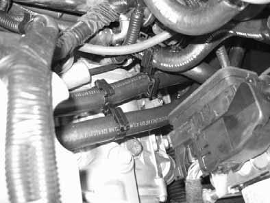
17 Coolant connection Pull off hose between engine outlet and heat exchanger inlet on heat exchanger. Cutting point 7 Push back heat guard. Cutting point Hose section of heat exchanger inlet Cutting point 8 Hose on heat exchanger inlet C 9 Before connecting, fill the coolant hoses with coolant. Hose of engine outlet Connection on heat exchanger inlet Connection to engine outlet A 0 808A_EN 7
![Spacer acket [x]](/docs-images/73/69205482/images/18-0.jpg "spacer acket")
18 Spacer acket [x] spacer acket Spacer acket [x] spacer acket 808A_EN 8


![Included hose section as scuff guard [x] Fuel line Hose section, 0 mm dia.](/docs-images/73/69205482/images/19-2.jpg "hose clamp [x] Connection on heater unit Mecanyl fuel pipe and metering pump cable harness lines Ensure proper installation position of metering pump, see")
19 Fuel Connection CAUTION! Open the vehicle's fuel tank cap, ventilate the tank and then re-close the tank lock. Catch any fuel running off with an appropriate container. Install fuel line and metering-pump wiring harness so that they are protected against stone impact. Unless specified otherwise, always fasten using cable ties. Mount the fuel line and wiring harness with rub protection on sharp edges. WARNING! The fuel line and wiring harness are routed to the metering pump in as shown in the wiring harness routing diagram. Included hose section as scuff guard [x] Fuel line Hose section, 0 mm dia. hose clamp [x] Connection on heater unit Mecanyl fuel pipe and metering pump cable harness lines Ensure proper installation position of metering pump, see "Installation Instructions. Installation location in front of vehicle fuel tank! Original vehicle nut Angle acket Silent block, flanged nut [x] Metering pump 5 Rubber-coated pipe clamp Installation location of metering pump A_EN 9
![Fuel line from heater unit on pressure side of metering pump [side with connector]. Hose section, 0 mm dia.](/docs-images/73/69205482/images/20-0.jpg "hose clamps [x] Wiring harness of metering pump, connector mounted Fuel line metering pump 6 Separate 90 molded hose at marking Discard section 5 mm Preparing fuel standpipe 7 5")

20 Fuel line from heater unit on pressure side of metering pump [side with connector]. Hose section, 0 mm dia. hose clamps [x] Wiring harness of metering pump, connector mounted Fuel line metering pump 6 Separate 90 molded hose at marking Discard section 5 mm Preparing fuel standpipe 7 5 Cut closure off existing removal connection piece and push on short end of 90 molded hose. Fuel line 0 mm dia. hose clamp [x] Fuel sender 5 Cable tie Removing fuel 8 80 molded hose, 0 mm dia. hose clamp [x] Fuel line from fuel standpipe on intake side of metering pump [side without connector]. Check the position of the components; adjust if necessary. Check that they have free clearance. Connecting to metering pump 9 808A_EN 0


21 Combustion air Combustion air pipe Hose clamp combustion air pipe 0 Combustion-air intake pipe 8 mm dia. p-clamp; rubber coating removed Combustion-air intake muffler Existing hole, M6 rivet nut, M6x0 bolt, spring lock washer muffler 808A_EN


 rubber isolator")
22 Exhaust system Exhaust pipe a = 0 mm Exhaust end section b = 0 mm Discard section X Preparing exhaust pipe a b X Radiator cross member Drill out existing hole to 9. mm dia., mount M6 rivet nut 7 muffler Exhaust muffler M6x5 bolt, 0 mm spacer, M6 flanged nut M6x0 bolt, spring lockwasher Perforated acket muffler Exhaust pipe Position red (rt) rubber isolator Heater unit Hose clamp exhaust pipe 808A_EN
 rubber isolator")

23 Ensure sufficient distance to neighboring components. Exhaust pipe Hose clamp [x] Push on red (rt) rubber isolator Exhaust end section 5 Red (rt) rubber isolator Bumper cover exhaust pipe and end section Positioning rubber isolator 6 808A_EN
.")
24 Final Work WARNING! Reassemble the disassembled components in reverse order. Check all hoses, clamps and all electrical connections for firm seating. Secure all loose cables using cable ties. Only use manufacturer-approved coolant. Spray the heater unit components with anti-corrosion wax (Tectyl 00K, Order No. 9). - Connect the battery - Fill and bleed the coolant circuit according to the vehicle manufacturer s specifications. - Set the digital timer. - Set the manual air conditioning or automatic air conditioning according to the "operating instructions for the end customer". - Check the proper operation of the additional heater, see the operating instructions/installation instructions. - Attach the "Switch off additional heater before refueling" sticker to the left-hand B-pillar. M8x0 bolt, spring lockwasher, flanged nut [x each] battery carrier 7 - Connect the battery - Fill and bleed the coolant circuit according to the vehicle manufacturer s specifications. - Set the digital timer. - Set the manual air conditioning or automatic air conditioning according to the "operating instructions for the end customer". - Check the proper operation of the additional heater, see the operating instructions/installation instructions. - Attach the "Switch off additional heater before refueling" sticker to the left-hand B-pillar. Feel the drive Webasto AG Postfach 80-8 Stockdorf Hotline 0805 / Hotfax 095 / A_EN Printed in Germany 0/007 Printing: Steffen
, we recommend not exceeding a switch-on time of 0 min.")

25 Operating Instructions for End Customer Please remove page and add to the vehicle operating instructions. Note: We recommend matching the heating time to the driving time. Heating time = driving time Example: For a driving time of approx. 0 min. (in one direction), we recommend not exceeding a switch-on time of 0 min. If the summer/winter switch option has been installed, this must be switched in accordance with the time of year. The heater unit will then only switch on the vehicle fan to ventilate the vehicle interior in the position Winter heat or in the position Summer. Before parking the vehicle, make the following settings: Set temperature to "max." Set fan to level "", or possibly "" Direct air outlet toward windshield Manual air conditioning 8 Set temperature to "max." Air outlet to windshield Automatic air-conditioning 9 808A_EN 5
ALWAYS follow all Webasto installation and repair instructions and observe all warnings.
 Water Heater Unit Feel the drive Thermo Top E Additional Heater Thermo Top C Additional Heater Thermo Top P Additional Heater e 00 000 e 00 000 e 00 004 Installation Instructions Hyundai H.5 CRDi from
ALWAYS follow all Webasto installation and repair instructions and observe all warnings.
 Water Heater Unit Feel the drive Thermo Top E Additional Heater Thermo Top C Additional Heater Thermo Top P Additional Heater e 00 0003 e 00 000 e 00 004 Installation Instructions Mitsubishi Pajero Diesel
ALWAYS follow all Webasto installation and repair instructions and observe all warnings.
 Water Heater Unit Feel the drive Thermo Top C Additional Heater Thermo Top P Additional Heater e 00 000 e 00 004 Installation Instructions Dodge Nitro Diesel from Model Year 007 Left-hand drive vehicle
ALWAYS follow all Webasto installation and repair instructions and observe all warnings.
 Water Heater Unit Feel the drive Thermo Top E Additional Heater e 00 000 Installation Instructions Chevrolet Aveo Gasoline Notchback from Model Year 006 Hatchback from Model Year 008 Left-hand drive vehicle
e ALWAYS follow all Webasto installation and repair instructions and observe all warnings.
 Water Heater Unit Thermo Top P Additional Heater e 00 004 Installation Instructions Toyota Land Cruiser J0 Diesel 4 5 6 from Model Year 005 For left-hand drive vehicles only Manual air conditioning not
ALWAYS follow all Webasto installation and repair instructions and observe all warnings.
 Water Heater Unit Feel the drive Thermo Top E Additional Heater Thermo Top C Additional Heater Thermo Top P Additional Heater e 00 000 e 00 000 e 00 004 Installation Instructions Toyota Hilux Diesel from
ALWAYS follow all Webasto installation and repair instructions and observe all warnings.
 Water Heater Feel the drive Thermo Top E Parking Heater Thermo Top C Parking Heater Thermo Top P Parking Heater e 00 000 e 00 000 e 00 004 Installation instructions Toyota Avensis Diesel from Model Year
ALWAYS follow all Webasto installation and repair instructions and observe all warnings.
 Water Heater Unit Feel the drive Thermo Top E Additional Heater Thermo Top C Additional Heater e 00 000 e 00 000 Installation Instructions Alfa Romeo 47 Gasoline and Diesel from Model Year 00 Left-hand
ALWAYS follow all Webasto installation and repair instructions and observe all warnings.
 Water Heater Feel the drive Thermo Top E Parking Heater Thermo Top C Parking Heater Thermo Top P Parking Heater e 00 0003 e 00 000 e 00 004 Installation documentation Nissan X-Trail Diesel from Model Year
ALWAYS follow all Webasto installation and repair instructions and observe all warnings.
 Water Heater Feel the drive Thermo Top E Parking Heater Thermo Top C Parking Heater Thermo Top P Parking Heater e 00 000 e 00 000 e 00 004 Installation documentation Mitsubishi Colt / Colt CZ / Colt CZC
ALWAYS follow all Webasto installation and repair instructions and observe all warnings.
 Water Heater Unit Feel the drive Thermo Top E Additional Heater Thermo Top C Additional Heater e 00 000 e 00 000 Installation Instructions Subaru Forester.0 Boxer Diesel from Model Year 009 Left-hand drive
ALWAYS follow all Webasto installation and repair instructions and observe all warnings.
 Water Heater Unit Feel the drive Thermo Top E Additional Heater e 00 0003 Installation Instructions Opel Meriva Diesel from Model Year 006 Left-hand drive vehicle WARNING! Hazard warning: Incorrect installation
ALWAYS follow all Webasto installation and repair instructions and observe all warnings.
 Water Heater Unit Feel the drive Thermo Top E Additional Heater Thermo Top C Additional Heater Thermo Top P Additional Heater e 00 000 e 00 000 e 00 004 Installation Instructions.4 TFSI from Model Year
Renault Scenic / Grand Scenic / Megane
 Water Heater Unit Feel the drive Thermo Top E Additional Heater Thermo Top C Additional Heater Thermo Top P Additional Heater e 00 000 e 00 000 e 00 004 Installation Instructions Renault Scenic / Grand
ALWAYS follow all Webasto installation and repair instructions and observe all warnings.
 Water Heater Thermo Top Evo Parking Heater e 00 058 Feel the drive Installation documentation Kia Sportage Diesel from Model Year 00 Left-hand drive vehicle Manual air conditioning Gear box AWD WARNING!
ALWAYS follow all Webasto installation and repair instructions and observe all warnings.
 Water Heater Feel the drive Thermo Top E Parking Heater Thermo Top C Parking Heater Thermo Top P Parking Heater e 00 0003 e 00 000 e 00 004 Installation documentation Mazda 6 Gasoline from Model Year 008
ALWAYS follow all Webasto installation and repair instructions and observe all warnings.
 Water Heater Unit Feel the drive Thermo Top E Additional Heater Thermo Top C Additional Heater Thermo Top P Additional Heater e 00 000 e 00 000 e 00 00 Installation Instructions Hyundai Santa Fe. l CRDi
ALWAYS follow all Webasto installation and repair instructions and observe all warnings.
 Water Heater Feel the drive Thermo Top E Parking Heater Thermo Top C Parking Heater e 00 000 e 00 000 Installation documentation Suzuki Splash Petrol from Model Year 008 Left-hand drive vehicle Manual
Water Heater Unit. Thermo Top C Additional Heater. Installation Instructions. FORD Connect. Gasoline and Diesel. not with automatic transmission
 Water Heater Unit Thermo Top C Additional Heater e 00 000 Installation Instructions FORD Connect Gasoline and Diesel 4 5 6 not with automatic transmission only applies to left-hand drive vehicles See Page
ALWAYS follow all Webasto installation and repair instructions and observe all warnings.
 Water Heater Feel the drive Thermo Top Evo Parking Heater e 00 058 Installation documentation Renault Koleos.0 Diesel from Model Year 009 Left-hand drive vehicle Automatic / manual air conditioning not
ALWAYS follow all Webasto installation and repair instructions and observe all warnings.
 Water Heater Feel the drive Thermo Top E Parking Heater Thermo Top C Parking Heater e 00 000 e 00 000 Installation instructions Subaru Legacy / Outback.0 and.5 Gasoline from Model Year 00 Left-hand drive
Citroen Jumpy / Fiat Scudo / Peugeot Expert
 Water Heater Feel the drive Thermo Top E Parking Heater Thermo Top C Parking Heater e 00 000 e 00 000 Installation documentation Citroen Jumpy / Fiat Scudo / Peugeot Expert Diesel from Model Year 007 Left-hand
The use of Thermo Top P is not permitted for priority heating of the passenger compartment displayed in this coolant circuit in this EBA!
 Water Heater Feel the drive Thermo Top E Parking Heater Thermo Top C Parking Heater e 00 000 e 00 000 Installation documentation Kia Sorento. CRDI from Model Year 00 Left-hand drive vehicle Automatic air-conditioning
ALWAYS follow all Webasto installation and repair instructions and observe all warning instructions.
 Water Heater unit Feel drive Supplementary heating Thermo Top C e 00 000 Installation instructions Dodge Caliber Diesel From model year 007 For left-hand drive vehicles only WARNING! Hazard warning: Incorrect
Citroen C1 / Peugeot 107 / Toyota Aygo
 Water Heater Feel the drive Thermo Top E Parking Heater Thermo Top C Parking Heater e 00 000 e 00 000 Installation documentation Citroen C / Peugeot 07 / Toyota Aygo Petrol from Model Year 005 For left-hand
ALWAYS follow all Webasto installation and repair instructions and observe all warnings.
 Water Heater Feel the drive Thermo Top E Parking Heater Thermo Top C Parking Heater Thermo Top P Parking Heater e 00 000 e 00 000 e 00 00 Installation documentation Citroen C Picasso Gasoline from Model
ALWAYS follow all Webasto installation and repair instructions and observe all warning instructions.
 Water heater unit Feel drive Thermo Top E Auxiliary Heating Thermo Top C Auxiliary Heating Thermo Top P Auxiliary Heating e 00 000 e 00 000 e 00 004 Installation instructions Toyota RAV 4 Petrol From model
ALWAYS follow all Webasto installation and repair instructions and observe all warnings.
 Water Heater Feel the drive Thermo Top Evo Parking Heater e 00 058 Installation documentation Dacia Duster / Sandero / Logan Petrol from model year 0 Left-hand drive vehicle Manual air conditioning WD
ALWAYS follow all Webasto installation and repair instructions and observe all warnings.
 Water Heater Unit Feel the drive Upgrade Instructions Upgrading from auxiliary heater to additional heater with engine preheating Diesel from Model Year 006 WARNING! Hazard warning: Incorrect installation
ALWAYS follow all Webasto installation and repair instructions and observe all warnings.
 Water Heater Feel the drive Thermo Top E Parking Heater Thermo Top C Parking Heater e 00 000 e 00 000 Installation documentation Skoda Yeti Diesel - CR from model year 00 Left-hand drive vehicle Climatronic
ALWAYS follow all Webasto installation and repair instructions and observe all warnings.
 Water Heater Thermo Top Evo Parking Heater e 00 058 Feel the drive Installation documentation Kia Sportage Petrol from Model Year 00 Left-hand drive vehicle Manual / automatic air-conditioning system Gear
ALWAYS follow all Webasto installation and repair instructions and observe all warnings.
 Water Heater Feel the drive Thermo Top E Parking Heater Thermo Top C Parking Heater Thermo Top P Parking Heater e 00 000 e 00 000 e 00 00 Installation documentation Citroen C Picasso Gasoline and Diesel
ALWAYS follow all Webasto installation and repair instructions and observe all warnings.
 Water Heater Feel the drive Thermo Top Evo Parking Heater e 00 058 Installation documentation Audi A6 / A6- Avant / Audi A7 Sportback.0 and.0 TDI quattro from model year 0 Left-hand drive vehicle Automatic
Water heater unit. Installation instructions. Peugeot Partner. Citroen Berlingo. Supplementary heating Thermo Top C. Table of Contents.
 Water heater unit Feel the drive Supplementary heating Thermo Top C e1 00 0002 Installation instructions Peugeot Partner Citroen Berlingo 6 4 1 2 3 5 Gasoline and diesel From model year 2003 Only for left-hand
Renault Laguna / - Grandtour / - GT / - Coupe
 Water Heater Thermo Top E Parking Heater Thermo Top C Parking Heater E 00 000 E 00 000 Installation Documentation Renault Laguna / - Grandtour / - GT / - Coupe Diesel from model year 008 Left-hand drive
ALWAYS follow all Webasto installation and repair instructions and observe all warnings.
 Water Heater Thermo Top C Motorcaravan Parking Heater E 00 000 Installation Documentation Fiat Ducato 50 / Multijet Diesel From model year 006 Left-hand drive vehicle Manual / automatic air-conditioning
ALWAYS follow all Webasto installation and repair instructions and observe all warnings.
 Water Heater Feel the drive Thermo Top E Parking Heater Thermo Top C Parking Heater e 00 000 e 00 000 Installation documentation VW Golf VI, Golf Plus, Golf Variant.6 and.0 TDI Common Rail from Model Year
part number:
 part number: 0968 0908 part number: 0968 Water Heater Unit Feel the drive Thermo Top E dditional Heater Thermo Top C dditional Heater Thermo Top P dditional Heater e 00 000 e 00 000 e 00 004 Installation
Mercedes Benz GLK 200 / 220 / 250 CDI (X204)
") Water Heater Feel the drive Thermo Top Evo 5+ Parking Heater e 00 058 Installation documentation Mercedes Benz GLK 00 / 0 / 50 CDI (X04) Diesel from model year 009 Left-hand drive vehicle Automatic air-conditioning
Water Heater Feel the drive Thermo Top Evo 5+ Parking Heater e 00 058 Installation documentation Mercedes Benz GLK 00 / 0 / 50 CDI (X04) Diesel from model year 009 Left-hand drive vehicle Automatic air-conditioning
Mercedes Benz C Class S204, W204 / from model 2007 GLK Class X204 / from model 2008
 Water Heater Feel the drive Thermo Top Evo5+ Parking Heater e 00 058 Installation documentation Mercedes Benz C Class S0, W0 / from model 007 GLK Class X0 / from model 008 Gasoline and Diesel Left-hand
Water heater unit. Thermo Top C Auxiliary Heating. for auxiliary heater C. Mazda 6 with standard Webasto Pre-heater. Diesel. 3 Pre-heater Z equipment
 Water heater unit Thermo Top C Auxiliary Heating e 00 000 Pre-heater Z equipment for auxiliary heater C 7 6 5 Mazda 6 with standard Webasto Pre-heater Up to Model 0 with chassis No. 600 000 -door and 5-door
Toyota Auris hybrid / Prius / Lexus CT200h
 Water Heater Feel the drive Thermo Top Evo Parking Heater e 00 058 Installation documentation Toyota Auris hybrid / Prius / Lexus CT00h.8 Petrol from Model Year 00 Left-hand drive vehicle Automatic air-conditioning
Opel Astra / Astra Caravan / Astra GTC / Astra Twin Top
 Water Heater Feel the drive Thermo Top C Parking Heater e 00 000 Installation documentation Opel stra / stra Caravan / stra GTC / stra Twin Top Petrol and Diesel from Model Year 004 Left-hand drive vehicle
D5W Z Auxiliary Heater Upgrade D5W Z Auxiliary Heater to Auxiliary Preheating System C
 Water Heater DW Z Auxiliary Heater Upgrade DW Z Auxiliary Heater to Auxiliary Preheating System C 6 FORD Mondeo.0 l TDCI Diesel. l TDCI Diesel Legend for Figure Blade-type fuse holder and blower relay
Manufacturer Model Type EG-BE No./ ABE Fiat Doblo 263 e3 * 2007 / 46 * 0007 *... Fiat Doblo Cargo 263 e3 * 2007 / 46 * 0002 *...
 Water Heater Thermo Top Evo Parking Heater E 00 058 Installation Documentation Fiat Doblo / Doblo Cargo Validity Manufacturer Model Type EG-BE No./ ABE Fiat Doblo 63 e3 * 007 / 46 * 0007 *... Fiat Doblo
Water Heater. Installation Documentation Renault Scenic / Grand Scenic / Megane. Thermo Top Evo Parking Heater. Validity
 Water Heater Thermo Top Evo Parking Heater E 00 058 Installation Documentation Renault Scenic / Grand Scenic / Megane Validity Manufacturer Model Type EG-BE No./ ABE Renault Scenic JZ e * 00 / 6 * 079
Manufacturer Model Type EG-BE No./ ABE Skoda Octavia 1Z e11 * 2001 / 116 * 0230 *...
 Water Heater Thermo Top Evo Parking Heater E 00 058 Installation Documentation Skoda Octavia Validity Manufacturer Model Type EG-BE No./ ABE Skoda Octavia Z e * 00 / 6 * 00 *... Motorisation Fuel Transmission
Manufacturer Model Type EG-BE No. / ABE Peugeot 3008 OU e1 * 2001 / 116 * 0377 *... Peugeot 5008 O e2 * 2007 / 46 * 0004 *...
 Water Heater Thermo Top Evo Parking Heater E 00 058 Installation Documentation Peugeot 008 / 5008 Validity Manufacturer Model Type EG-BE No. / ABE Peugeot 008 OU e * 00 / 6 * 077 *... Peugeot 5008 O e
Manufacturer Model Type EG-BE No./ ABE Alfa Romeo Giulietta 940 e3 * 2007 / 46 * 0027 *...
 Water Heater Thermo Top Evo Parking Heater E 00 058 Installation Documentation Alfa Romeo Giulietta Validity Manufacturer Model Type EG-BE No./ ABE Alfa Romeo Giulietta 940 e * 007 / 46 * 007 *... Motorisation
Manufacturer Model Type EG-BE No./ABE Peugeot Boxer 100 / 130 e3 * 2007 / 46 * 0045 *... Peugeot Boxer X2/50 L772 Peugeot Boxer X2/50 L773
 Air Heater Air Top 000 ST Air Heater E 00 00 Installation Documentation Fiat Ducato / Peugeot Boxer / Citroen Jumper Validity Fiat Manufacturer Model Type EG-BE No./ABE Fiat Ducato Multijet e * 007 / 46
Manufacturer Model Type EG BE No. / ABE BMW 3 Series Gran Turismo e1 * 2007 / 46 * 0559 *...
 K Water Heater Thermo Top Evo Parking Heater Island based circuit E 00 058 Installation Documentation BMW Series Gran Turismo F4 Validity Manufacturer Model Type EG BE No. / ABE BMW Series Gran Turismo
Manufacturer Model Type EG-BE No. / ABE Peugeot e2 * 2007 / 46 * 0080 *... Peugeot 508 SW 8 e2 * 2007 / 46 * 0080 *...
 Water Heater Thermo Top Evo Parking Heater E 00 058 Installation Documentation Peugeot 508 Validity Manufacturer Model Type EG-E No. / AE Peugeot 508 8 e * 007 / 46 * 0080 *... Peugeot 508 SW 8 e * 007
Manufacturer Model Type EG BE No. / ABE Audi A4 B9 e1 * 2001 / 116 * 0430 *...
 K Water Heater Thermo Top Evo Parking Heater E 00 058 Installation Documentation Audi A4 Validity Manufacturer Model Type EG BE No. / ABE Audi A4 B9 e * 00 / 6 * 040 *... Motorisation Fuel Transmission
Visit for more technical information and downloads.
 Visit for more technical information and downloads. Water Heater Thermo Top Evo Parking Heater E 00 058 Installation Documentation Toyota Landcruiser LC50 Validity Manufacturer Model Type EG-BE No. / ABE
Manufacturer Model Type EG BE No. / ABE Citroen C4 NC e2 * 2007 / 46 * 0040
 K Water Heater Thermo Top Evo Parking Heater Island based circuit With FuelFix E 00 058 Installation Documentation Citroen C Validity Manufacturer Model Type EG BE No. / ABE Citroen C NC e * 007 / 6 *
BlueHeat Coolant Heater
 BlueHeat Coolant Heater Thermo Top VW Jetta Beginning Model Year: 00 Special instructions for these models Part locations may differ slightly dependent on the vehicle model. Legend BlueHeat Coolant Heater,
Manufacturer Model Type EG BE No. / ABE Audi A1 8X e1 * 2007 / 46 * 0414
 K Water Heater Thermo Top Evo Parking Heater E 00 058 With FuelFix Installation Documentation Validity Manufacturer Model Type EG BE No. / ABE 8X e * 007 / 46 * 044 Motorisation Fuel Transmission type
Manufacturer Model Type EG BE No. / ABE VW Passat 3C e1 * 2001/116 * 0307 *... VW Passat 3C e1 * 2007 / 46 * 0547 *
 Water Heater Thermo Top Evo Parking Heater E 00 058 Installation Documentation VW Passat / CC Validity Passat Manufacturer Model Type EG BE No. / BE VW Passat C e * 00/6 * 007 *... VW Passat C e * 007
Installation Documentation VW Golf VII / Golf VII Sportsvan / Passat and Skoda Superb MQB
 K Water Heater Thermo Top Evo Parking Heater E 00 058 Installation Documentation VW Golf VII / Golf VII Sportsvan / Passat and Skoda Superb MQB Validity Manufacturer Model Type Model year EG BE No. / ABE
BlueHeat Coolant Heater
 BlueHeat Coolant Heater Thermo Top Ford F-50/350 Super Duty 6.4 Liter TT Diesel 6.8 Liter V0 Gasoline Beginning Model Year: 008 Special instructions for these models Part locations may differ slightly
Manufacturer Model Type EG-BE No. / ABE Citroen C5 R... e1 * 2001/116 * 0347 *... Citroen C5 R... e1 * 2001/116 * 0360 *...
 Water Heater Thermo Top Evo Parking Heater E 00 058 Installation Documentation itroen 5 / Peugeot 407 Validity Manufacturer Model Type EG-E No. / E itroen 5 R... e * 00/6 * 0347 *... itroen 5 R... e *
Verified equipment variants: Climatronic Passenger compartment monitoring (can be switched off in case of Golf)
") H Webasto Comft Air-Conditioning Control Installation Documentation VW / Skoda / Seat Validity Manufacturer Model Type Model year EG BE No. / ABE VW Golf VII AU From model year 03 e * 007 / 46 * 063 *...
H Webasto Comft Air-Conditioning Control Installation Documentation VW / Skoda / Seat Validity Manufacturer Model Type Model year EG BE No. / ABE VW Golf VII AU From model year 03 e * 007 / 46 * 063 *...
Parts and Accessories Installation Instructions
 Parts and Accessories Installation Instructions F 46 3 EVA Headlight Cleaning System (SRA) BMW 3 Series (E 46) The installation time is approx. 3.5 hours, but this may vary depending on the condition of
2015+ F-150 Active Exhaust Kit Installation Instructions P/N: (1117-5E292LITE)
") 2015+ F-150 Active Exhaust Kit Installation Instructions P/N: 422104 (1117-5E292LITE) 39555 Schoolcraft Rd, Plymouth MI, 48170 800.59.ROUSH 2015+ Ford F-150 Active Exhaust Kit Installation Instructions
2015+ F-150 Active Exhaust Kit Installation Instructions P/N: 422104 (1117-5E292LITE) 39555 Schoolcraft Rd, Plymouth MI, 48170 800.59.ROUSH 2015+ Ford F-150 Active Exhaust Kit Installation Instructions
Parts and Accessories Installation Instructions
 Parts and Accessories Installation Instructions 5 224 B Installation Kit Headlight Cleaning System Mini (R5/R53) LHD and RHD Installation time approx. 1.5-2 hours, which can vary according to the condition
Installation instructions, accessories - Fuel driven heater 912-D
 XC90 Section Group Weight(Kg/Pounds) Year Month 8 87 2002 10 XC90 2003 D5244T, XC90 2004 D5244T, XC90 2005 D5244T AW50/51 AWD, XC90 2006 D5244T, XC90 2006 D5244T AW50/51 AWD D5244T R8703687 Page 1 of 20
Volkswagen New Beetle 1.8 Liter 4-Cyl. 5V Turbo OBD II Engine Mechanical 19 Engine-Cooling system (Page GR-19)
") 19 Engine-Cooling system (Page GR-19) Cooling system components, removing and installing Continued coolant circulation pump (V51), checking Coolant hose connection diagram Coolant pump, removing and installing
19 Engine-Cooling system (Page GR-19) Cooling system components, removing and installing Continued coolant circulation pump (V51), checking Coolant hose connection diagram Coolant pump, removing and installing
Parts and Accessories Installation Instructions
 Parts and Accessories Installation Instructions R 1 3 5 2 4 F 38 0213 B Basic retrofit kit for hands-free facility for upgrading various mobile phones BMW 7 Series (E38) LHD without telephone preparation
Parts and Accessories Installation Instructions
 Parts and Accessories Installation Instructions Park Distance Control (PDC) Rear Retrofit BMW Z4 (E 85) The installation time is approx. 4 hours, but this may vary depending on the condition of the car
Installation Instructions for Lingenfelter GM 2500 Suburban & Yukon XL Auxiliary Fan System (with AC clutch controlled fan output)
") Installation Instructions for Lingenfelter 2007-2013 GM 2500 Suburban & Yukon XL Auxiliary Fan System (with AC clutch controlled fan output) PN L300080607 Revision - 1.1 Lingenfelter Performance Engineering
Installation Instructions for Lingenfelter 2007-2013 GM 2500 Suburban & Yukon XL Auxiliary Fan System (with AC clutch controlled fan output) PN L300080607 Revision - 1.1 Lingenfelter Performance Engineering
C FORD F250 / F L POWERSTROKE DIESEL WITH AUTOMATIC TRANSMISSIONS ONLY
 EXHAUST BRAKES C40019 1999-2003 FORD F250 / F350 7.3L POWERSTROKE DIESEL WITH AUTOMATIC TRANSMISSIONS ONLY Getting Started Thank you and congratulations on your purchase of a Pacbrake exhaust retarder.
WPS-104 Heater Installation Instructions For 500EFI, 700 XP, & Crew Applications
 WPS-104 Heater Installation Instructions For 500EFI, 700 XP, & Crew Applications ORDER OF INSTALLATION FOR A COMPLETE ENCLOSURE OF A RANGERWARE WPS (Weather Protection System) IS AS FOLLOWS: 1. Heater
1 Cable harness for trailer hitch 3 Supporting plate, detachable ball neck 4 Bolts 12 Detachable ball neck 12a Mount X52 Trailer hitch connector
 an3110p8080aa Page 1 of 3 Retrofit trailer hitch AN31.10- P- 8080AA Retrofit trailer hitch 5.11.99 MODEL 163.113 /136 / 154 /172 #A as of 145273, 163.113 / 136 /154 / 172 #X as of 708319, 163.128 / 175
Fuel supply system, servicing (vehicles with front wheel drive and 1.8 ltr. turbo or 2.8 ltr. engine)
") Page 1 of 49 20-6 Fuel supply system, servicing (vehicles with front wheel drive and 1.8 ltr. turbo or 2.8 ltr. engine) Note: VAG1921 spring clamp pliers are recommended for installation Always replace
Page 1 of 49 20-6 Fuel supply system, servicing (vehicles with front wheel drive and 1.8 ltr. turbo or 2.8 ltr. engine) Note: VAG1921 spring clamp pliers are recommended for installation Always replace
Recommended tools: Estimated install time: Parts list:
 Congratulations on your purchase of the A.W.E. Tuning Center Vent Boost Gauge for your Audi A4/S4. While the install is fairly straight forward, please review these instructions carefully before attempting
Installation instructions. Thermo Top. Thermo Top Thermo Top T Tele Thermo Top. Thermo Top S. Thermo Top S Tele Thermo Top S BW 50 DW 50 8/1995
 Water Heater Operating instructions Installation instructions Thermo Top Thermo Top Thermo Top T Tele Thermo Top Thermo Top S Thermo Top S Tele Thermo Top S BW 50 DW 50 Petrol Diesel 8/1995 Table of contents
18SP680Rev3 EPA04 MBE 4000 Car Hauler Low Pressure Fuel Lines
 8SP680Rev3 EPA04 MBE 4000 Car Hauler Low Pressure Fuel Lines KIT DESCRIPTION These service kits include all necessary parts to replace the low pressure fuel lines between the fuel filter housing and fuel
Parts and Accessories Installation Instructions
 Parts and Accessories Installation Instructions F 53 7 W Retrofit auxiliary heating system BMW X5 (E 53) with M57 engine (diesel) The installation time is approx..5-4.5 hours (see important information),
INSTALLATION INSTRUCTIONS
 INSTALLATION INSTRUCTIONS Accessory Application Publications No. P/N 08E49-S2A-100 2004 S2000 AII 26325 Issue Date OCT 2003 PARTS LIST Hood switch harness TOOLS AND SUPPLIES REQUIRED #2 Phillips screwdriver
AN82.10-P-0001FB Retrofit xenon headlamps MODEL 210.### 1# as of
 AN82.10-P-0001FB Retrofit xenon headlamps 3.11.99 MODEL 210.### 1# as of 1.7.99 Illustrated on model 210 sedan A51 Headlamp range adjustment rear A52 Front (headlamp range adjustment) E1 Left lamp unit
Parts and Accessories Installation Instructions
 Parts and Accessories Installation Instructions Active cruise control retrofit (ACC) BMW 7 Series (E 65, E 66) LHD Important information The retrofit kit is for use within the BMW dealership organisation
ARTICLE BEGINNING SERVICE PRECAUTIONS
 Page 1 of 96 ARTICLE BEGINNING SERVICE PRECAUTIONS WARNING: WARNING: CAUTION: When performing any inspection or service procedure on this vehicle, ensure following service precautions are followed to prevent
PERFECT FIT SERIES IN-DASH HEAT/ COOL/ DEFROST 1969 CHEVROLET CAMARO/ FIREBIRD NOTE: INSTRUCTIONS DEPICT CAMARO
 specializing in AIR CONDITIONING, PARTS AND SYSTEMS for your classic vehicle PERFECT FIT SERIES IN-DASH HEAT/ COOL/ DEFROST 1969 CHEVROLET CAMARO/ FIREBIRD NOTE: INSTRUCTIONS DEPICT CAMARO CONTROL & OPERATING
Diesel Cooker X 100. Installation Instructions
 Diesel Cooker X 100 Installation Instructions Index 1. Legal notices 2. Overview and function 3. Installation 4. Fuel supply 5. Electrical connections 6. Exhaust system 7. Initial start-up 8. Technical
Consists of. Date:17/02/2011 Page 1/8
 Consists of 470518 Qty. Product 4 1 DEFA Termina - interior heater with holder 1 1 DEFA Futura - time program controller/timer 3 1 DEFA MultiCharger 1203 - battery charger/relay 6 1 DEFA Extension cable
JODALE PERRY. Parts List & Mounting Instructions. Jacobsen HR9016 JDP BUILT FOR LIFE
 JODALE PERRY Parts List & Mounting Instructions Jacobsen HR9016 JDP BUILT FOR LIFE Jacobsen HR9016 Mounting Instructions Standard Parts 1 - LH Rear Mounting Bracket 1 - RH Rear Mounting Bracket 1 - Front
Original BMW Accessories. Installation Instructions.
 Original BMW Accessories. Installation Instructions. Anti-Theft Alarm System Retrofit BMW 3 Series Saloon (E90) BMW 3 Series Coupé (E92) Retrofit kit no.: 65 2 0 399 635 Anti-theft alarm system retrofit
BMW Parts and Accessories Installation Instructions
 BMW Parts and Accessories Installation Instructions 6 Z Automatic air conditioning system BMW Series Compact (E 6/5) LHD and RHD with N engine Specialist knowledge required. Only for use in the BMW dealer
Cantilever Series Mounting Instructions Chevy Express (AD) present
 present") Chevy Express (AD)- 2003-present Preparing the Gate 1. Remove the platform, mounting kit, and bridge assemblies, which are banded to the main assembly. Leave the banding that holds the folding cylinder
Chevy Express (AD)- 2003-present Preparing the Gate 1. Remove the platform, mounting kit, and bridge assemblies, which are banded to the main assembly. Leave the banding that holds the folding cylinder
Installation Instructions
 Suzuki Samurai 1 Inch and 2 Inch Body Lift Kit (SKU# SSP-BL) Installation Instructions Background: These instructions are designed for installing the 2 body lift. Our approach is to raise the entire body
ORIGINAL MINI ACCESSORIES. INSTALLATION INSTRUCTIONS.
 ORIGINAL MINI ACCESSORIES. INSTALLATION INSTRUCTIONS. Retrofit Kit Additional Headlight MINI 3-door (F56) MINI 5-door (F56) MINI CLUBMAN (F54) MINI CONVERTIBLE (F57) MINI COUNTRYMAN (F60) Installation
Installation and Commissioning of Auxiliary Power Unit
 Models PC6012 PC6013 PC6014 PC6015 PC6022 PC6023 PC6024 Installation and Commissioning of Auxiliary Power Unit 30-871-21 Rev. E Warning & Cautions Vehicles with longer wheel bases should have the APU mounted
Cooling system components, removing and installing
 19-1 Cooling system components, removing and installing Note: When the engine is warm the cooling system is under pressure. If necessary release pressure before starting repair work. Hoses are secured
LEXUS GS 350/450h ILLUMINATED DOOR SILLS Preparation
 Preparation Part Number: PT922-30120 (GS350) PT922-30130 (GS450h) NOTE: Part number of this accessory may not be the same as the part number shown. Kit Contents Item # Quantity Req'd. Description 1 1 Illuminated
INSTALLATION INSTRUCTIONS
 28 INSTALLATION INSTRUCTIONS SECTION - AIR SPRING SECTION 2 - AIR ACCESSORY 2-5 ! IMPORTANT PLEASE DON T HURT YOURSELF, YOUR KIT OR YOUR VEHICLE. TAKE A MINUTE TO READ THIS IMPORTANT INFORMATION. This
Installation Instructions
 SLP GM/Chevrolet LS3 COIL COVER KIT 2010+ Camaro 5.3L/6.2L 2007+ GMT900 5.3L/6.2L PN: 620038 Installation Instructions Important Notes: Before installing your SLP Coil Cover Kit, please read the installation
Parts and Accessories. Installation Instructions.
 Parts and Accessories. Installation Instructions. Retrofit alarm system BMW 5 Series (E 60) Retrofit kit No. 65 73 0 304 463 Installation time The installation time is approx 5.0-5.5 hours, but this may
Cooling system components, removing and installing
 Page 1 of 40 19-1 Cooling system components, removing and installing WARNING! The cooling system is pressurized when the engine is warm. When opening the expansion tank, wear gloves and other appropriate
Original BMW Accessories. Installation Instructions.
 Original BMW Accessories. Installation Instructions. BMW Integrated Navigation. BMW Series (F20, F2) BMW 2 Series (F22, F23, F45, F46) BMW 3 Series (F30, F3, F34, F35) BMW 4 Series (F32, F33, F36) BMW