Annular pressure (damper) seals Stiffness principle. Seals as load support elements. Rotordynamic effects.
|
|
|
- Jessica Paul
- 6 years ago
- Views:
Transcription

1 Modern Lubrication Theory FALL 014 TAMU Date: Today s material Notes 1a Annular pressure (damper) seals Stiffness principle. Seals as load support elements. Rotordynamic effects. Notes 1b Hydrostatic / hydrodynamic bearings Stiffness principle. Effect of fluid compressibility. Force coefficients Observations/Announcements Homework 4, Homework 5 due Read: Chupp et al., 006, AIAA JPP, Childs, Chp 4, pp
2 Design and Analysis of High Speed Pumps Damper Seals and Hydrostatic Bearings for Pump Applications Dr. Luis San Andres Mast-Childs Professor Presentation for lectures 1(a) and 1(b) Based on Lecture (3) delivered at Von Karman Institute (006) (Nov update)
3 Damper Seals & Hydrostatic Bearings LEARNING OBJECTIVES a) Physical mechanism for generation of direct stiffness in annular pressure seals & hydrostatic bearings. Select design conditions to obtain maximum (optimum) stiffness b) Bulk-flow equations for prediction of the flow and force coefficients in annular pressure seals and hydrostatic bearings c) Predictions for two water seals, long and short, for application as neck ring and interstage seals. Effect of seal length and inlet swirl on rotordynamic force coefficients d) Discussion on design of hydrostatic bearing for water pump and to replace oil-lubricated bearings. Effect of angled injection and considerations for improvements in stability margin 3
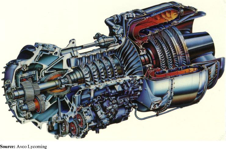
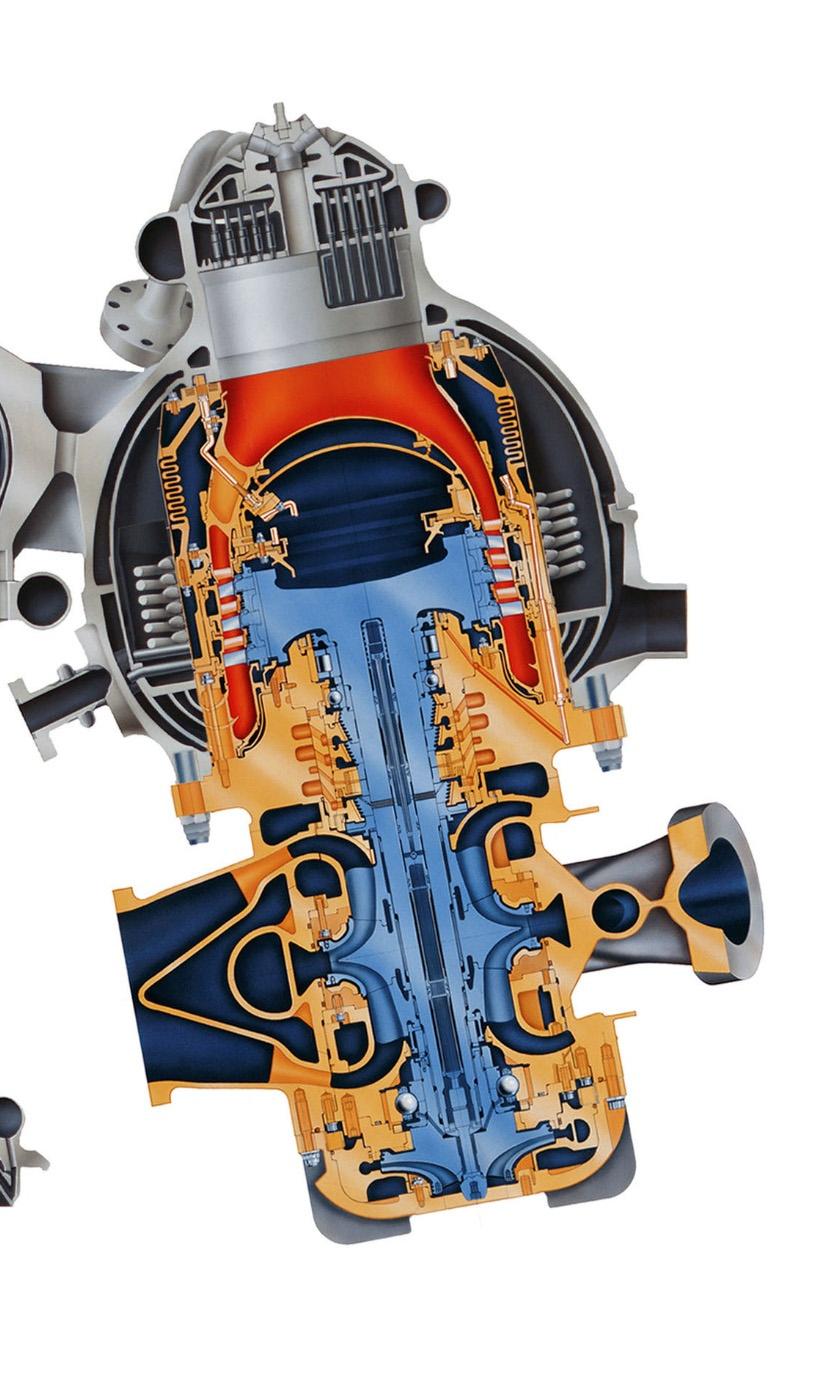
4 Annular pressure seals Seals (annular, labyrinth or honeycomb) separate regions of high pressure and low pressure and their principal function is to minimize the leakage (secondary flow); thus improving the overall efficiency of a rotating machine extracting or delivering power to a fluid. Inter-stage seal Impeller eye or neck ring seal Balance piston seal Figure 1 Seals in a Multistage Centrifugal Pump or Compressor 4
5 Count the seals.. 5
6 Keep counting seals.. 6

7 Keep counting more seals.. 7

8 Keep counting... 8

9 And keep counting seals.. 9

10 Annular Pressure Seals Non-contacting fluid seals are leakage control devices minimizing secondary flows in turbomachines. Seals use process liquids of light viscosity as the working fluid. The dynamic force response of pressure seals has a primary influence on the stability response of highperformance turbomachinery. Annular seals, although geometrically similar to plain journal bearings, show a flow structure dominated by turbulence and fluid inertia effects. Operating characteristics unique to seals are * large axial pressure gradients, * large clearance to radius ratio (R/c) < 500, while * the axial development of the circumferential velocity determines the magnitude of crosscoupled (hydrodynamic) forces. 10
11 Annular Pressure Seals Due to their relative position within a rotor-bearing system, seals modify sensibly the system dynamic behavior. Seals typically "see" large amplitude rotor motions. This is particularly important in back-to-back compressors and long-flexible multiple stage pumps. Figure 1 Straight-Through and Back-to-back Compressors and 1st Mode Shapes 11
12 Annular pressure seals Intentionally roughened stator surfaces (macro texturing) reduce the impact of undesirable cross-coupled dynamic forces and improve seal stability. These seals are common practice in current damper seal technology for cryogenic turbo pumps. Annular seals acting as Lomakin bearings have potential as support elements (damping bearings) in high speed cryogenic turbo pumps as well in process fluid applications. Figure 3 Honeycomb and round hole pattern seals for turbopump 1
13 The Lomakin effect in pressurized seals The Lomakin Effect: generation of support (direct) stiffness L Axial velocity, V z shaft c D P s Axial velocity, V z c P a Process P s fluid at high Ps P a P e L Exit pressure P a z 4: Geometry of an annular pressure seal 5: Inertial pressure drop due to a sudden contraction The direct stiffness is due to the pressure drop at the seal inlet plane and its close interaction with the pressure drop (and flow resistance) within the seal lands (even without shaft rotation). The entrance effect is solely due to fluid inertia accelerating the fluid from the upstream (stagnant) pressure supply to a flow with a high axial speed and reduced static pressure. Figures 4 & 5 13
14 The Lomakin effect: a centering stiffness Force - P supply C V z eccentricity Inlet pressure drop Bernoulli equation: P+ρ (1+)V z /=const. continuity equation: ρv z c=const. + P inlet C V z c V z P - P inlet (1+ξ) ρv z / (1+ξ)ρV z / V z L / C Ω + c V z P Original as per Dr. M. Arghir presentation (006) P exit 14
15 Centering stiffness from an annular seal K B L c o K P s P a Optimum stiffness * Typical design condition pressure drop at inlet Too large clearance Or short seal pe: pressure ratio (entrance/supply) pressure drop in land Too tight clearance Or Long seal Seal wear enlarges clearance and increases leakage Figure 6 Stiffness versus entrance pressure ratio (simple model) 15
16 Annular Pressure Seals The Lomakin effect Incompressible fluid, turbulent flow V z = (1 + P s P ) + a L c f z Axial velocity (leakage) decreases with increase of inlet loss () and friction factor (fz) and length of land in seal. P e P a = 1 + P s P a (1+ ) f z c L Entrance pressure into seal decreases as inlet loss () increases and as land friction factor (fz) decreases or land length increases L Ps c Pa Axial velocity, V z Ps Pe 5: Inertial pressure drop due to a sudden contraction Pa z 16
17 Force Coefficients in Annular Seals D D c P e P s rotor L L stator Depiction of an annular pressure seal P a V z Axial velocity Axial pressure field Y Seal reaction forces are functions of the fluid properties, flow regime, operating conditions and geometry. For small amplitudes of rotor lateral motion: forces represented with linearized stiffness, damping and inertia force coefficients: - F F x y K K xx yx K K xy yy C Y C xx yx C C xy yy M Y M xx yx M M xy yy Y 17
18 18 Force/Moment coefficients in seals Seals also generate moment coefficients due to tilts (angulations) of rotor. Most complete model: 16 stiffness, 16 damping and 16 inertia coefficients Y Z Y Seal with dynamic translations (,Y) and angulations (, Y) Y Y Y Y Y Y Y Y Y Y Y Y Y Y Y Y Y Y Y Y Y Y Y Y Y Y Y Y Y Y Y Y e e M M M M M M M M M M M M M M M M - e e C C C C C C C C C C C C C C C C - e e K K K K - K K K K K K K K K K K K = - M M F F Figure 7
19 19 Bulk-flow Analysis: governing equations 0 t h hv z hv x z x z V V x V t V h U V h x P h z x x x J x x z V x V V t V h V h z P h z z x z z z Flow Continuity Circumferential Momentum transport Axial momentum transport Pa - Turbulent flow with fluid inertia effects - Mean flow velocities average across film (h) - No accounting for strong recirculation zones z Vz Ps Vx
20 Bulk-flow analysis: inlet conditions Boundary Conditions -Inlet pressure loss due to fluid inertia (Lomakin effect) - Inlet swirl determined by upstream condition (implementation of swirl-brakes) -Exit pressure without recovery loss, typically P e P s - 1 (1+ ) V z, V x R Numerical Solution -Analytical solutions for short length seals (centered condition) See Childs textbook -Numerical solutions for realistic geometries use CFD techniques (staggered grids, upwinding, etc) and predict (4 or 16) K,C,M force/moment coefficients. Radial baffles retarding fluid swirl Fluid path Ps Seal z Vz Vx Rotor speed rotor Figure 8 Anti swirl brake at inlet or pressure seal 0
21 Dynamic forced performance of annular seals Example: (centered seal) Fluid: water at 30 C ( 0.79 cpoise, 995 kg/m3) Centered seal (e=0): No static load D = mm (6 inch), Short seal (neck ring seal) L/D=0.0 Long seal (inter stage seal) L/D= 0.50 c = mm, nominal clearance & worn clearance (c) smooth rotor and stator surfaces Nominal speed = 3600 rpm, Pressure drop 34.4 bar neck ring seal & inter stage seal or balance piston Standard design practice: find influence of seal wear on leakage and rotordynamic coefficients Pressure drop P ~ RPM Inlet loss coefficient ξ=0.1 Inlet swirl α=0.5 and 0.0 (without and with swirl break) Influence on cross-coupled stiffness and stability Table 1 Geometry and operating conditions of water seals in a liquid pump 1
22 Entrance pressure into seal LONG SEAL SHORT SEAL entrance pressure Pressures vs shaft speed bar operating speed 3600 rpm rotor speed (RPM) water seal, L/D=0.50, c=0.190 mm, D=15 mm No effect of inlet swirl on entrance pressure c c RPM Ps Supply pressure Supply pressure Nominal clearance (C) Twice clearance (worn) L/D=0.50 entrance pressure Pressures vs shaft speed bar rotor speed (RPM) water seal, L/D=0.0, c=0.190 mm, D=15 mm No effect of inlet swirl on entrance pressure operating speed 3600 rpm c Supply pressure Supply pressure Nominal clearance (C) Twice clearance (worn) - Worn seal leads to lower entrance pressure loss due to increase in flow rate (reduction in land flow resistance) - Short seal leads has lowest entrance pressure due to increase in leakage c L/D=0.0 Figure 9 Supply and entrance pressures for two water seals, L/D=0.50 and 0.0, and two clearances (c and c)
23 Entrance pressure ratio into seal Entrance pressure ratio LONG SEAL Inlet Pressure vs shaft speed c c (Pe-Pa)/(Ps-Pa) rotor speed (RPM) RPM water seal, L/D=0.50, c=0.190 mm, D=15 mm No effect of inlet swirl on entrance pressure operating speed 3600 rpm nominal C, swirl=0.5 nominal C, swirl=0.0 Twice clearance (worn) swirl=0.5 L/D=0.50 Entrance pressure ratio Inlet Pressure vs shaft speed SHORT SEAL c c (Pe-Pa)/(Ps-Pa) L/D=0.0 rotor speed (RPM) water seal, L/D=0.50, c=0.190 mm, D=15 mm No effect of inlet swirl on entrance pressure operating speed 3600 rpm nominal C, swirl=0.5 nominal C, swirl=0.0 Twice clearance (worn) swirl=0.5 RPM - Worn seal leads to higher entrance pressure loss due to increase in flow rate (reduction in land flow resistance) - Short seal leads to even larger inlet pressure loss due to increase in leakage Figure 9 Entrance pressure ratio for two water seals and two clearances (c and c) 3
24 Seal leakage LONG SEAL SHORT SEAL Leakage vs shaft speed kg/s Nominal condition operating speed 3600 rpm water seal, L/D=0.50, c=0.190 mm, D=15 mm No effect of inlet swirl Nominal clearance (C) Twice clearance (worn) Leakage vs shaft speed kg/s water seal, L/D=0.0, c=0.190 mm, D=15 mm No effect of inlet swirl operating speed 3600 rpm Flow rate c c Flow rate c c Nominal clearance (C) Twice clearance (worn) rotor speed (RPM) L/D= L/D=0.0 rotor speed (RPM) RPM & Psupply - Leakage is proportional to RPM ~ P & not proportional to clearance - Worn seal leaks more Longer seal leaks less - No influence of inlet swirl 1/ Figure 10 Leakage (flow rate) for two water seals, L/D=0.50 & 0.0, and two clearances 4
25 Drag power LONG SEAL SHORT SEAL Drag Power Power vs shaft speed kw Nominal condition c c water seal, L/D=0.50, c=0.190 mm, D=15 mm minor effect of inlet swirl operating speed 3600 rpm Drag Power Power vs shaft speed kw water seal, L/D=0.0, c=0.190 mm, D=15 mm minor effect of inlet swirl operating speed 3600 rpm Nominal clearance (C) Twice clearance (worn) "" no swirl 1 Nominal clearance (C) Twice clearance (worn) "" no swirl 1 c c rotor speed (RPM) L/D= L/D=0.0 rotor speed (RPM) RPM & Psupply - Drag Power ~ RPM - Long seal draws more power (~ 5 times) - No effect of clearance. As C increases, so does circ. Reynolds # - No effect of inlet swirl Figure 11 Drag Power for two water seals, L/D=0.50 & 0.0, and two clearances 5
26 Rotordynamic coefficients lateral motions Seal reaction forces: - F F x y K K xx yx K K xy yy C Y C xx yx C C xy yy M Y M xx yx M M xy yy Y Reduced model: K = KYY, KY = -KY C = CYY, CY = -CY M = MYY, MY = -MY Whirl frequency ratio WFR ~ Centered Condition KY C Assumes: No static load capability Circular centered orbit : measure of rotordynamic stability Y 6
27 Seal direct stiffness LONG SEAL SHORT SEAL Direct Stiffness vs shaft speed Kxx=Kyy [MN/m] Nominal condition water seal, L/D=0.50, c=0.190 mm, D=15 mm negligible effect of inlet swirl operating speed 3600 rpm Direct Stiffness vs shaft speed Kxx=Kyy [MN/m] water seal, L/D=0.0, c=0.190 mm, D=15 mm negligible effect of inlet swirl operating speed 3600 rpm Stiffness c c Stiffness Nominal clearance (C) Twice clearance (worn) ""no swirl c c 10 Nominal clearance (C) Twice clearance (worn) ""no swirl rotor speed (RPM) L/D= L/D=0.0 rotor speed (RPM) RPM & Psupply - Direct stiffness ~ Pressure supply ~ RPM - Long seal has ~ x larger stiffness than short seal - Worn clearance causes ~ 50% drop in direct stiffness. It will affect pump WET natural frequencies - No effect of inlet swirl 1/ Figure 1 Direct stiffnesses K=KYY for two water L/D seals & two clearances 7
28 Seal direct stiffness Direct stiffness Dim Direct Stiffness vs pressure ratio Kxx=Kyy [-] L/D=0.5 L/D=0. L/D=0., c c L/D=0.5, c, a=0.5 L/D=0.5, c, a=0.0 L/D=0.5, c, a=0.5 L/D=0.5, c, a=0.0 L/D=0., c, a=0.5 L/D=0., c, a=0.0 L/D=0., c, a=0.5 L/D=0., c, a=0.0 Simple formula water seal, L/D=0.50, 0.0, c=0.190 mm, D=15 mm negligible effect of inlet swirl K c k L D ( P s Pa ) L D ( P c s Pa L/D=0.5, c L/D=0.5, c L/D=0., c Entrance Pressure ratio L/D=0.50, Direct stiffness follows simple formula K c ) RPM increases Simple formula Figure Dimensionless stiffnesses K=KYY for two water L/D seals & two clearances 8
29 Seal cross-coupled stiffness LONG SEAL SHORT SEAL Stiffness Cross Stiffness vs shaft speed Kxy=-Kyx [MN/m] Nominal condition Nominal clearance (with swirl) "" no swirl Twice clearance (worn) "" no swirl c water seal, L/D=0.50, c=0.190 mm, D=15 mm large effect of inlet swirl operating speed 3600 rpm c 1xC 50% inlet swirl xc no inlet swirl Stiffness Cross Stiffness vs shaft speed Different scale Inlet swirl =0 Kxy=-Kyx [MN/m] Nominal clearance (with swirl) "" no swirl Twice clearance (worn) "" no swirl water seal, L/D=0.0, c=0.190 mm, D=15 mm large effect of inlet swirl operating speed 3600 rpm c c 1xC 50% inlet swirl xc no inlet swirl rotor speed (RPM) L/D=0.50 RPM & Psupply rotor speed (RPM) L/D=0.0 - Cross stiffness ~ RPM & 1/clearance - Long seal has ~ 5x more cross-stiffness than short seal - Worn clearance drop in cross-stiffness. - Inlet swirl ~ 0 has most pronounced effect (KY <0 favors stability) Figure 13 Cross stiffnesses KY=-KY for two water L/D seals and two clearances 9
30 Seal direct damping coefficients LONG SEAL SHORT SEAL Damping Damping vs shaft speed Cxx=Cyy Cxy=-Cyx [kns/m] Nominal condition Cxx Nominal clearance (with swirl) Cxy Cxx Twice clearance (worn) Cxy c water seal, L/D=0.50, c=0.190 mm, D=15 mm little effect of inlet swirl c operating speed 3600 rpm Cxx 50% inlet swirl 1xC xc Damping Different Damping scale vs shaft speed Cxx=Cyy Cxy=-Cyx [kns/m] Cxx Nominal clearance (with swirl) Cxy Cxx Twice clearance (worn) Cxy water seal, L/D=0.0, c=0.190 mm, D=15 mm little effect of inlet swirl c operating speed 3600 rpm c 1xC 50% inlet swirl Cxx xc 40 0 Cxy 10 5 Cxy rotor speed (RPM) RPM & Psupply L/D= rotor speed (RPM) - Direct damping ~ effective turbulent flow viscosity & 1/clearance - Long seal has ~ 5x more direct damping than short seal - Worn clearance drop in damping - Inlet swirl no effect. C >> CY RPM L/D=0.0 Figure 14 Damping C=CYY & CY=-CY for two L/D water seals and two clearances 30
31 Seal added mass or fluid inertia coefficients Added mass LONG SEAL Direct Inertia vs shaft speed c c Mxx=Myy [kg] L/D=0.50 Rotor Speed (RPM) water seal, L/D=0.50, c=0.190 mm, D=15 mm negligible effect of inlet swirl operating speed 3600 rpm Nominal clearance (C) Twice clearance (worn) ""no swirl Added mass SHORT SEAL Different Direct Inertia scale vs shaft speed Mxx=Myy [kg] c c Nominal condition L/D=0.0 rotor speed (RPM) water seal, L/D=0.0, c=0.190 mm, D=15 mm negligible effect of inlet swirl operating speed 3600 rpm Nominal clearance (C) Twice clearance (worn) ""no swirl RPM & Psupply - Direct inertia invariant with speed & proportional to 1/clearance - Long seal has ~ 0x more added mass than short seal - Worn clearance drop in added mass - Inlet swirl no effect. M >> MY - Large inertia will affect wet pump critical speeds Figure 15 Inertia M=MYY for two L/D water seals and two clearances 31
32 Fluid inertia Its magnitude M fluid DL c M steel steel M D 3 L 1 c tanh L D L D D L D=15.4 mm c =0.190 mm =0.79 cpoise =995 kg/m3 LONG SEAL L/D=0.5 SHORT SEAL L/D= M 4.03kg M fluid kg M steel 10.84kg M 3.88 M steel 0. M.91kg M fluid kg M steel 4.34kg M 0.67 M steel -Fluid mass inside film is just a few grams, but. since added mass is proportional to Diameter and 1/clearance M can be larger than mass of solid steel of same dimensions 3
33 Whirl frequency ratio stability indicator LONG SEAL SHORT SEAL Whirl frequency ratio Whirl ratio vs shaft speed WFR c c Nominal clearance (with swirl) "" no swirl Twice clearance (worn) "" no swirl c c rotor speed (RPM) water seal, L/D=0.50, c=0.190 mm, D=15 mm large effect of inlet swirl operating speed 3600 rpm % inlet swirl 1xC 0. no inlet swirlinlet swirl =0 xc L/D=0.50 Whirl frequency ratio Whirl ratio vs shaft speed WFR Nominal condition Nominal clearance (with swirl) "" no swirl Twice clearance (worn) "" no swirl negative values L/D=0.0 rotor speed (RPM) water seal, L/D=0.0, c=0.190 mm, D=15 mm large effect of inlet swirl operating speed 3600 rpm 50% inlet swirl no inlet swirl xc 1xC 0.50 RPM & Psupply - WFR always 0.50 for inlet swirl = 0.50 Stable up to x critical speed - Inlet swirl = 0.0 drops WFR, in particular for short seal. - Inlet swirl =0.0 does not help greatly in long seal with tight clearance Figure 16 Whirl frequency ratio for two L/D water seals & two clearances 33
34 Textured surface annular seals Hole-Pattern Seal Unwrap Honeycomb Seal Unwrap -Machined roughness in seal surfaces aids to increase friction thus reducing leakage. - Surface texturing also reduces development of mean circumferential flow velocity, thus decreasing cross-stiffnesses. -Proven improvement in stability margins in pumps and compressors -Texturing works only on stationary surface. Opposite rotordynamic effect if rotor is rough. 34


35 Hole pattern seal for compressors Hole damper seal replacing labyrinth seal in division wall of back-to-back compressor 005 Turbomachinery Symposium 35


36 Hole pattern seal INSTABILITY Waterfalls before (with original labyrinth seals) and after installation of holepattern seal in division wall - 36
37 Questions? 37
38 Hydrostatic Bearings for pump applications 38
39 Hydrostatic Bearings for pump applications External pressure source forces fluid to flow between two surfaces, thus enabling their separation and the ability to support a load without contact. Advantages Support very large loads. The load support is a function of the pressure drop across the bearing and the area of fluid pressure action. Load does not depend on film thickness or lubricant viscosity Long life (infinite in theory) without wear of surfaces Provide stiffness and damping coefficients of very large magnitude. Excellent for exact positioning and control. Disadvantages Require ancillary equipment. Larger installation and maintenance costs. Need of fluid filtration equipment. Loss of performance with fluid contamination. High power consumption: pumping losses. Limited LOAD CAPACITY ~ f(psupply) Potential to induce hydrodynamic instability in hybrid mode operation. Potential to show pneumatic hammer instability with compressible fluids 39

40 Hydrostatic bearings for turbopumps Low cost primary power cryogenic turbo-pumps (TP) are compact, operate at high speeds, and require of externally pressurized fluid film bearings to support radial and thrust loads. Hybrid thrust & radial bearings enable smaller and lighter turbopumps with no DN life limitations Large stiffness (accuracy of positioning) and damping force coefficients allow for unshrouded impellers with increased TP efficiency 40
41 Support stiffness in a Hydrostatic Bearing P s Q r Feed restrictor Flow through restrictor = Flow through film lands P a L Film land P R, recess pressure b L Fluid flow, Ql Figure 18: Geometry of a simplified 1-D hydrostatic bearing P a h p h Q Q r r Q Q c o A C o d d 4 18 c P P s s P P R R orifice capillar P s Supply pressure P R, recess pressure Q 3 B h P B h PR P 1 x 1 L 3 a Land flow P a Film land L Figure 19: Typical pressure drop in a hydrostatic bearing (laminar flow without fluid inertia effects, incompressible fluid) Figures 18 & 19 b L P a As film thickness decreases, resistance in land increases, thus reducing flow rate and increasing pressure in pocket or recess. Stiffness generated from changes in pocket pressure 41
42 Static support stiffness in a hydrostatic bearing 0.4 Dimensionless stiffness for simple HB Typical design condition K c Ps Area stiffness (dimensionless) 0. orifice capillar Figure 0: Static stiffness for simple hydrostatic bearing (laminar flow w/o fluid inertia effects, incompressible fluid). Figure ifi pocket pressur ratio (Pr/Ps) Low recess pressure Too large clearance Or too small orifice diameter High recess pressure drop Too tight clearance Or too large orifice No need of journal rotation Stiffness is proportional to supply pressure and bearing (pocket) area. Stiffness is inversely proportional to clearance Stiffness changes quickly with variations in pocket pressure Hydrostatic bearings have LIMIT load capacity 4
43 Traditional hydrostatic bearing design: * large pocket area (80-90 % of total area) * deep pocket depth * large orifice discharge volume Applications: low or null surface speed, low frequencies, nearly incompressible fluids (water or mineral oil) produces very large DIRECT Stiffness. Warning: This design should NEVER be used with compressible liquids or gases 43
44 Fluid Compressibility Effects Pneumatic Hammer is a self-excited instability (loss of damping) in poorly designed hydrostatic bearings for applications with compressible liquid and gases. The instability arises due to trapped fluid volume in the bearing pockets generating a dynamic pressure that lags journal motions by ~ (+)90 degrees. Remedies to AVOID (reduce and even eliminate) pneumatic hammer are WELL KNOWN (documented analysis and operation verification) and can be implemented easily at the design stage. 44
45 Fluid compressibility Effects Low frequency Loss of damping if fluid is compressible Dimensionless stiffness and damping K/Ko C/Co Coefficients for hydrostatic bearing C K excitation frequency/break frequency K f ( ) K B 0 f 1 ; 1 f High frequency Stiffness Hardening effect Complete loss of damping C ( ) C f Coefficients depend on BREAK frequency: B Z 1 V rec 0 3 h0 B 6 L A function of fluid bulk modulus pocket volume Ko C B o Figure Frequency dependent force coefficients for simple hydrostatic bearing 45
46 Whirl frequency ratio of centered HJB WFR K C Y f K Y 0.5 C Whirl frequency ratio Ko C B o B Q P r R 0 Z 1 V rec 0 Z 0 1 V rec 0 3 h0 B 6 L WFR in a hydrostatic bearing can be WORSE than that of a plain journal bearing due to fluid compressibility. Worse conditions are for gases and liquid hydrogen in a cryogenic turbo pump. In aerostatic bearings pockets are not machined to reduce (eliminate) pneumatic hammer For LH, very shallow pockets and reduced pocket area are recommended. 46
47 Hydrostatic Bearings for Cryogenic Turbo Pumps Radial hydrostatic bearings Thrust hydrostatic bearing Figure 3 Advanced Liquid Hydrogen Turbopump [] 47


48 Hydrostatic Bearings for Cryogenic Turbo Pumps Radial hydrostatic bearing Thrust hydrostatic bearing Radial hydrostatic bearing for LH TP - Knurled surface Figure 4 Hydrostatic radial and thrust bearings for cryogenic turbopump 48
 - No accounting for strong recirculation")
49 49 Bulk-flow Analysis of Hydrostatic Bearings 0 t h hv z hv x z x z V V x V t V h U V h x P h z x x x J x x z V x V V t V h V h z P h z z x z z z Flow Continuity Circumferential Momentum transport Axial momentum transport -Turbulent flow with fluid inertia effects -Mean flow velocities average across film (h) - No accounting for strong recirculation zones
50 Bulk-flow Analysis of Hydrostatic Bearings MR Ps Supply pressure Pocket pressure field with angled injection P s Feed orifice and Supply volume PR, recess pressure HR PR R P R P Film land Fluid flow, M Film land Pa b R H b Figure 6: Turbulent flow pressure distribution in a pocket of a hybrid bearing Flow continuity M R C d A o P P M V s R 1/ t R Pressure rise before edge P R P R x b x h h R R R V Pressure rise at edge P R P R (1 ) e 1 e h h h R V x, z Figure 6 Pocket pressures: angled & radial injection 50
51 Bulk-flow Analysis of Hydrostatic Bearings Small amplitude radial motions (,Y) at frequency () to derive zeroth order equations for equilibrium flow field: flow rate, load capacity, power loss, temperature raise first-order equations for perturbed flow field: (stiffness, damping and inertia) force coefficients Z P H R dz d K M i C ;,, Y A B Numerical method of solution: SIMPLEC method, extension of control volume method, + component method for superposition of hydrostatic and hydrodynamic effects. Sensitivity Analysis Bearing force coefficients and performance parameters are most sensitive to orifice entrance loss coefficient. Numerical Analysis : Hydrostatic Bearings 51
52 Dynamic Performance of Hydrostatic Bearings Example: Water bearing replacing oil lubricated bearing Fluid: water at 30 C ( 0.79 cpoise, 995 kg/m3) D=L = mm (6 inch) c=0.10 mm (4 mil), nominal clearance 5 pockets: l= 51 mm, arc 41, depth= mm Orifice diameter: 3. mm (Cd=0.80) Static load =Wx = 5000 N smooth rotor and stator surfaces Nominal speed = 3600 rpm, Pressure drop 34.4 bar c = 1.33x oil bearing Pocket depth/c = 3.75 Pocket area = 19% to avoid hammer STATIC LOAD FROM PUMP WEIGHT Pressure supply ~ RPM (bleed off from pump discharge) Table Inlet loss coefficient ξ=0.1 Inlet swirl α=0.50 RADIAL AND TANGENTIAL INJECTION Geometry and operating conditions of HJBs for a liquid pump Influence on cross-coupled stiffness and stability 5
53 Hydrostatic Bearing Orifice diameter selection Stiffness coefficients HJB design: [MN/m] Kxy=-Kyx At nominal operating condition Ps-Pa=34.4 bar, 3600 rpm Design Kxx = Kyy Kxx=Kyy 3.0 mm Selected orifice diameter Orifice diameter (mm) L=D=0.15 m, c=10 um, 5 pocket (l=l/3, arc =4 deg) Kxy = -Kyx Orifice diameter Selected diameter Kxx (MN/m) Kxy (MN/m) Stiffness coefficients HJB design: Kxx=Kyy= Kyy Kxx (MN/m) Kxy (MN/m) Kxx-Mxx w^ At nominal operating condition Ps-Pa=34.4 bar, 3600 rpm Kxx - Mxx Kxy=-Kyx Kxy = -Kyx 3.0 mm Selected orifice diameter L=D=0.15 m, c=10 um, 5 pocket (l=l/3, arc =4 deg) Pocket pressure ratio Pocket pressure ratio Orifice diameter - Operating condition: 3.6 krpm & 34.4 bar pressure supply (NO LOAD) - Select orifice diameter to MAIMIZE direct stiffness - No influence of angled injection on K Figure 7 Direct and cross-coupled stiffnesses versus orifice diameter and pocket pressure for water hydrostatic bearing. Nominal operating condition, centered bearing (no load) 53
54 Hydrostatic Bearing Orifice diameter selection Parameters HJB design: Design Pocket pressure ratio HJB flow rate (kg/s) Power (kw) At nominal operating condition Ps-Pa=34.4 bar, 3600 rpm flow selected orifice diameter L=D=0.15 m, c=10 um, 5 pocket (l=l/3, arc =4 deg) Drag power (kw) Flow rate (kg/s) Supply pressure Pocket pressure ratio Orifice diameter (mm) Pocket pressure ratio Parameters HJB design: Damping Mxx = Myy At nominal operating condition Ps-Pa=34.4 bar, 3600 rpm selected design Inertia Mxy = -Myx L=D=0.15 m, c=10 um, 5 pocket (l=l/3, arc =4 deg) Mxx (kg) Mxy (kg) Cxx (kns/m) Cxy (kns/m) Cxx = Cyy Cxy = Cyx Orifice diameter (mm) Pocket pressure ratio Selected diameter - Drag power, flow rate and pocket pressure increase with orifice diameter - Direct damping and inertia coefficients decrease Figure 8 Performance parameters for water hydrostatic bearing versus orifice diameter. Nominal operating condition, centered bearing (no load) 54
55 Hydrostatic Bearings Static Load Performance Operating journal eccentricity L=D=0.15 m, c=10 um, 5 pocket (l=l/3, arc =4 deg), orifice do=3. mm Attitude angle L=D=0.15 m, c=10 um, 5 pocket (l=l/3, arc =4 deg), orifice do=3. mm operation operating condition, Ps-Pa=34.4 bar [deg] Radial operating condition, Ps-Pa=34.4 bar e/c [fraction of clearance] tangential injection radial injection STATIC LOAD = 5 kn rotor speed (RPM) Tangent x load direction y tangential injection radial injection STATIC LOAD = 5 kn rotor speed (RPM) RPM & Psupply RPM & Psupply Load (W)=5 kn - At operating condition, static eccentricity is small, 10% of clearance (c=0.10 mm) - Large eccentricities at low speeds because pressure supply is low (hydrodynamic operation) -Tangential injection reduces attitude angle: will result in improved stability of bearing Figure 9 Journal eccentricity and attitude angle versus rotor speed. Water hydrostatic bearing with radial and tangential injection 55
56 Hydrostatic Bearings Peak pressures Max film pressures L=D=0.15 m, c=10 um, 5 pocket (l=l/3, arc =4 deg), orifice do=3. mm Mass flow rate L=D=0.15 m, c=10 um, 5 pocket (l=l/3, arc =4 deg), orifice do=3. mm [bar] operating condition, Ps-Pa=34.4 operation bar supply pressure function of pump speed [kg/s] operating condition, Ps- Pa=34.4 bar Tangent Psupply Radial tangential injection radial injection Supply pressure flow R & tang tangential injection radial injection STATIC LOAD = 5 kn rotor speed (RPM) STATIC LOAD = 5 kn rotor speed (RPM) Load (W)=5 kn - Flow rate is proportional to rotor speed since supply pressure (~ RPM ) - Max. film pressure is proportional to supply pressure, Max. Pressure ~ RPM - Tangential injection increases edge recess pressure no influence on flow rate - Large flow rate (90 LPM) typical of application 1/ Figure 30 Maximum film pressures and flow rate versus rotor speed. Water hydrostatic bearing with radial and tangential injection 56
57 Hydrostatic Bearings Drag Torque Drag Torque [N-m] operating condition, Ps-Pa=34.4 bar tangential injection radial injection STATIC LOAD = 5 kn operation Tangent L=D=0.15 m, c=10 um, 5 pocket (l=l/3, arc =4 deg), orifice do=3. mm Drag Power Radial rotor speed (RPM) [kw] operating condition, Ps-Pa=34.4 bar L=D=0.15 m, c=10 um, 5 pocket (l=l/3, arc =4 deg), orifice do=3. mm Radial Tangent tangential 1 injection radial injection STATIC LOAD = 5 kn rotor speed (RPM) Load (W)=5 kn - Drag torque & power proportional to RPM - Tangential injection decreases power & torque since it retards development of circumferential speed. Care at low speeds and high pressures (reverse journal rotation) Figure 31 Torque and drag power versus rotor speed. Water hydrostatic bearing with radial and tangential injection 57
58 Hydrostatic Bearings STIFFNESSES Direct stiffnesses Kxx, Kyy L=D=0.15 m, c=10 um, 5 pocket (l=l/3, arc =4 deg), orifice do=3. mm Cross stiffnesses Kxy, -Kyx L=D=0.15 m, c=10 um, 5 pocket (l=l/3, arc =4 deg), orifice do=3. mm 900 operating condition, Ps-Pa=34.4 bar [MN/m] 800 operation y 700 x 600 Tangent Radial Kxx: tangential injection 00 radial injection Kyy tangential injection 100 radial injection STATIC LOAD = 5 kn Rotor Speed (RPM) RPM & Psupply [MN/m] STATIC LOAD = 5 kn x operating condition, Ps-Pa=34.4 bar y Rotor Speed (RPM) Kxy: tangential injection radial injection -Kyx tangential injection Tangent radial injection radial injection Radial tangential injection RPM & Psupply Load (W)=5 kn - At low speeds, bearing operates under hydrodynamic conditions since feed pressure is too low. All coefficients are large since operating eccentricity (e/c) is large - At operating speed, direct stiffness K~KYY & KY=-KY since (e/c)~0 : near centered operation. - Tangential injection reduces greatly cross-coupled stiffness. Figure 3 1 Stiffness coefficients versus rotor speed. Water hydrostatic bearing with radial and tangential injection 58
59 Hydrostatic Bearings DAMPING Direct damping Cxx, Cyy L=D=0.15 m, c=10 um, 5 pocket (l=l/3, arc =4 deg), orifice do=3. mm Cross damping Cxy, -Cyx L=D=0.15 m, c=10 um, 5 pocket (l=l/3, arc =4 deg), orifice do=3. mm [kns/m] x y operating condition, Ps-Pa=34.4 bar Cxx: tangential injection radial injection Cyy tangential injection radial injection Different scale [kns/m] operating condition, Ps-Pa=34.4 bar operation Cxy: tangential injection radial injection -Cyx tangential injection radial injection Radial radial injection STATIC LOAD = 5 kn Tangent Radial rotor speed (RPM) x y STATIC LOAD = 5 kn Tangent tangential injection rotor speed (RPM) Load (W)=5 kn - At low speeds, all coefficients are large since operating eccentricity (e/c) is large (Hydrodynamic operation) - At operating speed, direct damping C~CYY & CY=-CY since (e/c)~0 : near centered operation. - From moderate to high speeds, C > CY - Tangential injection reduces cross-coupled damping small effect on rotordynamics Figure 33 1 Damping coefficients versus rotor speed. Water hydrostatic bearing with radial and tangential injection 59
60 Hydrostatic Bearings ADDED MASS Direct inertia [kg] x Mxx: tangential injection radial injection Myy tangential injection y Mxx, Myy Tangent radial injection operation L=D=0.15 m, c=10 um, 5 pocket (l=l/3, arc =4 deg), orifice do=3. mm operating condition, Ps- Pa=34.4 bar Radial Cross-inertia 5 Different [kg] scale Mxy: tangential injection radial injection +Myx tangential injection -Mxy radial injection x y Mxy, -Myx Tangent L=D=0.15 m, c=10 um, 5 pocket (l=l/3, arc =4 deg), orifice do=3. mm operating condition, Ps-Pa=34.4 bar Radial STATIC LOAD = 5 kn Rotor Speed (RPM) STATIC LOAD = 5 kn rotor speed (RPM) Load (W)=5 kn - Large fluid inertia effect (~ 160 kg) >> kg = solid steel piece (L,D) - Direct inertia changes little with rotor speed - At operating speed, direct inertia M~MYY & MY=-MY since (e/c)~0 : near centered operation. - For all speeds, M > MY - Tangential injection reduces cross-coupled inertia small effect on rotordynamics Figure 34 1 Fluid inertia coefficients versus rotor speed. Water hydrostatic bearing with radial and tangential injection 60
61 Whirl Frequency Ratio & Critical mass Whirl frequency ratio L=D=0.15 m, c=10 um, 5 pocket (l=l/3, arc =4 deg), orifice do=3. mm Critical mass L=D=0.15 m, c=10 um, 5 pocket (l=l/3, arc =4 deg), orifice do=3. mm [-] Radial [kg] operating condition, Ps-Pa=34.4 bar Tangent tangential injection radial injection tangential injection against shaft rotation Tangent tangential injection radial injection Fully stable WFR =<0 operating condition, operation Ps-Pa=34.4 bar Radial rotor speed (RPM) STATIC LOAD = 5 kn rotor speed (RPM) Load (W)=5 kn - WFR ~ 0.60 for radial injection bearing, Critical mass ~ 8,000 kg - With tangential injection: WFR drops rapidly towards 0.10 at operating point and beyond. Critical mass at least 10x larger than for radial injection - In other applications (ex: LOx bearing), benefit of tangential injection is lost at very high speeds when hydrodynamic effects dominate flow -Critical mass results applicable to RIGID ROTOR only Figure 35 Whirl frequency ratio & Critical Mass versus rotor speed. Water hydrostatic bearing with radial and tangential injection 61
62 Hydrostatic Bearings Recommendations Hydrostatic bearings have WFR > ~ 0.50 limiting their application to ~x critical speed. Limiting speed condition can be worse if fluid is compressible and pockets are too deep & large area. To reduce risk of hydrodynamic instability & increase bearing stability margin: -Texture bearing surface Proven with macro rough surfaces such as Knurled, round hole and tire truck pattern tested successfully -Angled injection against rotation Retards circumferential flow swirl, effectiveness reduces at high rotor speeds, Can induce backward whirl. Tested successfully -Bearing asymmetry Geometrically induce stiffness orthotropy (K > KYY) Axial feed grooves, mechanical preload, etc. Tested & patented! 6


63 Hydrostatic Bearings Recommendations Flexure-pivot Tilting pad hybrid bearing Tilting pads accommodate shaft motions to load direction, no generation of cross coupled stiffnesses, KY ~ KY ~ 0. No stability margin. Wire EDM construction allows for reliable hydrostatic feeding. Tested in water, oil and gas applications 63
64 Hydrostatic Bearings for Cryogenic Turbo Pumps To avoid pneumatic hammer: * reduce area pocket/land area to ~ 15-5% * pocket depth to clearance ratio ~ 10 or less * design and construct orifices without supply discharge volume (no pressure recovery zone) P a L Film land P s Q r P R, recess pressure Feed restrictor L b Fluid flow, Ql P a h p h Design parameter, P < < 1, TYP 0.1 or less DP = (PR -PA) 3 Npocket (Vpocket+Vsupply orifice) Kfluid (Z+1) Area_bearing x Cradial_clearance Kfluid: Fluid Bulk modulus Area_bearing ~ D L Z= (PR -PA) a (PS -PR) a= for orifice restrictors PS, PR, PA: supply, recess or pocket, discharge pressures 64
65 Hydrostatic Bearings for Cryogenic Turbo Pumps Cryogenic fluid hydrostatic bearing design: * small pocket area (15-5 % of total area) * shallow pocket depth * small or null orifice discharge volume Application: high surface speeds, low and high frequencies, compressible liquids (LO, LH, LN) + Angled injection against rotation to reduce cross-coupled stiffnesses (avoid hydrodynamic instability) Nearly inherent restrictor type, i.e. orifice coefficient regulated by clearance 65
66 Gas hydrostatic bearing design * Null pocket area (0 % of total area) * Inherent restrictor type, i.e. orifice coefficient regulated by clearance Applications: low and high surface speeds, low and high frequencies, All Gases (air, GO, GH, GN) + angled injection against rotation to reduce cross-coupled stiffnesses 66
67 Hydrostatic Bearings Model Validation HYDROJET radial hydrostatic bearings Tests at TAMU with water (1000 psi (70 bar) max, 5 krpm max). + 0 bearings x 3 clearances & pocket depths, different pocket shapes, macro-roughness (surface textured) bearings, angled injection. Gas Honeycomb seals Water Lomakin Bearings (Snecma-SEP) Oil tilting and flexure pivot journal bearings HYDROTHRUST axial thrust hydrostatic bearings NONE available in literature for high speed, high pressure (turbulent flows) Concerns: centrifugal and advection fluid inertia cause severe fluid starvation in bearing and reduced axial stiffness coefficients due to effect of added mass coefficients TESTs verified predictions 67
68 Needs in turbomachinery largest power output to weight ratio, reliability and performance, compact with low number of parts, extreme temperatures and pressures, Rotordynamics low friction and wear automated agile processes coatings: nanopowders surface conditioning environmentally safe and friendly. oil-free machinery inert gas buffer sealing Desired features of support elements (bearings and seals) High stiffness and damping coefficients Linearity with respect to amplitudes of rotor motion Avoidance of rotordynamic instability due to hydrodynamic effects Controllable features to avoid surge/stall, etc. 68
69 Hydrostatic Bearings Learn more See Publications For complete list of computational model predictions and comparisons to test data (over 30 journal papers and 10+ technical progress reports to NASA, USAF, P&W, Rocketdyne, Snecma-SEP, Northrop Grumman) 69
70 Bulk-flow Analysis of Hydrostatic Bearings At Texas A&M: Hydrojet & Hydrothrust Equations for flow in film lands of bearing Equations for flow in pockets of hydrostatic bearing Flow conditions Mass conservation, Bulk-Flow momentum in circumferential and axial directions (D), Energy transport for mean flow temperature Various surface temperature models Fluid inertia effects at entrance and exit flow regions. Global mass conservation: orifice inlet flow, flow from recess towards or from film lands, and rate of accumulation of fluid within pocket volume, Global momentum in circumferential direction due to angled injection. Global energy transport with adiabatic heat flow surfaces Laminar, laminar to turbulent transition and fully developed turbulent bulk-flow model. Turbulent flow closure model: Moody's friction factor including surface roughness. Fluid with variable properties f(p,t) Model for Cryogenic Hydrostatic Bearings 70
71 Hydrostatic Bearings Funding & Work to Date 40 k, Rocketdyne ( ), 110 k, Pratt & Whitney (1991-9), 360 k, NASA GRC ( ), 10 k, NASA MSFC (1998/99-001/) 9 k, Norhtop Grumman ( ) - (USET Program) Separate funding for performance evaluation and rotordynamics measurements for validation of radial bearing tool prediction All US turbo pump manufacturers and NASA, including SNECMA-SEP, use Hydrojet and Hydrothrust to model cryogenic fluid film bearings and seals. Other industries and Universities have benefited from technology. USET Program ( ) CLIN (a) non-linear forced response of fluid film bearing (98.5 k) CLIN (b) mixed flow regime lift off response (130.5 k) CLIN Experimental Study of Hydrostatic / Hydrodynamic Thrust Bearings (788 k) 71
72 Hydrostatic Bearings CFD models 3D CFD modeling of flow and pressure in POCKETS carried out by P&W (90 s) and also by Universite de Poitiers funded by Snecma- SEP (France, ). OBJECTIVEs: Predict complex flow field in pocket and extract empirical parameters for pressure loss at inlet to film lands and for development of pressure profile for angled injection bearings. Insert empirical parameters into D-bulk-flow codes for prediction of bearing rotordynamic force coefficients. Best published work: Mihai ARGHIR, Université de Poitiers, France. FINDINGS: 3D-CFD predictions are NOT better than D-bulk flow predictions when compared to test data (TAMU-Childs). TAMU codes are still unsurpassed in terms of accuracy of predictions and speed of execution. 7
Failure of a Test Rig Operating with Pressurized Gas Bearings: a Lesson on Humility
 Proceedings of ASME Turbo Expo 2015: Turbine Technical Conference and Exposition, June 15-19, 2015, Montreal, Canada GT2015-42556 Failure of a Test Rig Operating with Pressurized Gas Bearings: a Lesson
Introduction to rotordynamics and lubricated elements
 August 2016 Introduction to rotordynamics and lubricated elements Dr. Luis San Andres Mast-Childs Chair Professor Turbomachinery Laboratory Texas A&M University Lsanandres@tamu.edu 1 Turbomachinery A turbomachinery
A Test Rig for Evaluation of Thrust Bearings and Face Seals
 TRC-B&C-02-2015 TRC Project 32513/1519F2 May 2015 Year II A Test Rig for Evaluation of Thrust Bearings and Face Seals Luis San Andrés, Michael Rohmer, Scott Wilkinson Justification Compressors, turbochargers,
Notes 11. High Pressure Floating Ring Oil Seals
 Notes 11. High Pressure Floating Ring Oil Seals Outer seal P a Outer seal land Oil supply (P S +P) Shaft Inner seal land Anti-rotation pin Seal loading spring Inner seal Process Gas (P S ) Fig. 1 Typical
Introduction to triblogy, rotordynamics & lubricated elements
 August 2018 Introduction to triblogy, rotordynamics & lubricated elements Dr. Luis San Andres Mast-Childs Chair Professor Turbomachinery Laboratory Texas A&M University Lsanandres@tamu.edu 1 Tribology?
EFFECT OF LUBRICANT SUPPLY PRESSURE ON SFD PERFORMANCE: ENDS SEALED WITH O-RINGS & PISTON RINGS
 May 2017 Year V EFFECT OF LUBRICANT SUPPLY PRESSURE ON SFD PERFORMANCE: ENDS SEALED WITH O-RINGS & PISTON RINGS TRC-SFD-01-17 Bonjin Koo Leping Yu Graduate Research Assistants Luis San Andrés Mast-Childs
0 INTRODUCTION TO FLUID FILM BEARINGS AND SEALS
 Notes 0 INTRODUCTION TO FLUID FILM BEARINGS AND SEALS A turbomachinery is a rotating structure where the load and/or the driver handle a process fluid from which power is extracted or delivered to. Examples
Metal Mesh Foil Gas Bearings for Oil-Free Turbomachinery
 12 th National Conference on Gas Lubrication, Dry Gas Seal and Micro Gravity in China May 218 Metal Mesh Foil Gas Bearings for Oil-Free Turbomachinery An introduction to Oil-Free MTM requirements and metal
Structural and Rotordynamic Force Coefficients of a Shimmed Bump Foil Bearing: an Assessment of a Simple Engineering Practice
 Proceedings of ASME Turbo Expo 2015: Turbine Technical Conference and Exposition, June 15-19, 2015, Montreal, Canada Paper GT2015-43734 Structural and Rotordynamic Force Coefficients of a Shimmed Bump
XLTRC 2 TURBOMACHINERY RESEARCH CONSORTIUM ROTORDYNAMICS SOFTWARE SUITE
 XLTRC 2 TURBOMACHINERY RESEARCH CONSORTIUM ROTORDYNAMICS SOFTWARE SUITE WHAT IS XLTRC2? XLTRC2 is a suite of very fast, accurate and experimentally verified, and user- friendly codes for executing a complete
COMPARISON OF THE LEAKAGE CHARACTERISTICS OF THE STRAIGHT ANNULAR AND CONVERGENT SEALS. A Thesis SERAFETTIN USTUN
 COMPARISON OF THE LEAKAGE CHARACTERISTICS OF THE STRAIGHT ANNULAR AND CONVERGENT SEALS A Thesis by SERAFETTIN USTUN Submitted to the Office of Graduate Studies of Texas A&M University in partial fulfillment
APPLICATION OF A NEW TYPE OF AERODYNAMIC TILTING PAD JOURNAL BEARING IN POWER GYROSCOPE
 Colloquium DYNAMICS OF MACHINES 2012 Prague, February 7 8, 2011 CzechNC APPLICATION OF A NEW TYPE OF AERODYNAMIC TILTING PAD JOURNAL BEARING IN POWER GYROSCOPE Jiří Šimek Abstract: New type of aerodynamic
MEASUREMENTS OF ROTORDYNAMIC ROTOR SUPPORTED ON METAL MESH
 ASME Turbo Expo 213 GT213 June 3-7, 213, San Antonio, Texas, USA MEASUREMENTS OF ROTORDYNAMIC RESPONSE AND TEMPERATURES IN A ROTOR SUPPORTED ON METAL MESH FOIL BEARINGS Thomas Chirathadam Southwest Research
ROTATING MACHINERY DYNAMICS
 Pepperdam Industrial Park Phone 800-343-0803 7261 Investment Drive Fax 843-552-4790 N. Charleston, SC 29418 www.wheeler-ind.com ROTATING MACHINERY DYNAMICS SOFTWARE MODULE LIST Fluid Film Bearings Featuring
Year I. TRC-SEAL Luis San Andrés. Weilian Shan Graduate Research Assistant. May rd Turbomachinery Research Consortium Meeting
 33 rd Turbomachinery Research Consortium Meeting Predictions vs. Test Results for Leakage and Force Coefficients of a Fully Partitioned Pocket Damper Seal and a Labyrinth Seal Limitations of the Current
HYDROGEN COMPRESSOR SEAL CASE STUDY UTILIZING HALO (NON-CONTACTING, COMPLIANT) INTER-STAGE, IMPELLER EYE, BUFFER AND FAIL- SAFE SEALS
 INTER-STAGE, IMPELLER EYE, BUFFER AND FAIL- SAFE SEALS") HYDROGEN COMPRESSOR SEAL CASE STUDY UTILIZING HALO (NON-CONTACTING, COMPLIANT) INTER-STAGE, IMPELLER EYE, BUFFER AND FAIL- SAFE SEALS Author Information John Justak, President/CEO of ATGI Over 28 years
HYDROGEN COMPRESSOR SEAL CASE STUDY UTILIZING HALO (NON-CONTACTING, COMPLIANT) INTER-STAGE, IMPELLER EYE, BUFFER AND FAIL- SAFE SEALS Author Information John Justak, President/CEO of ATGI Over 28 years
NOVEL CARBON-GRAPHITE GAS BEARINGS FOR TURBOMACHINERY
 May 2018 NOVEL CARBON-GRAPHITE GAS BEARINGS FOR TURBOMACHINERY Luis San Andrés Mast-Childs Chair Professor Porous Type Gas Bearings Porous type gas bushing pads Porous type gas bearings (PTGB) have sub-micron
Experimental Response of a Rotor Supported on Flexure Pivot Hydrostatic Pad Gas Bearings
 Texas A&M University Mechanical Engineering Department Turbomachinery Laboratory Experimental Response of a Rotor Supported on Flexure Pivot Hydrostatic Pad Gas Bearings Research Progress Report to the
Dynamic Coefficients in Hydrodynamic Bearing Analysis Steven Pasternak C.O. Engineering Sleeve and Sleevoil Bearings 8/10/18 WP0281
 Dynamic Coefficients in Hydrodynamic Bearing Analysis Steven Pasternak C.O. Engineering Sleeve and Sleevoil Bearings 8/10/18 WP0281 Hydrodynamic Bearing Basics Hydrodynamic journal bearings operate by
CHAPTER 1. Introduction and Literature Review
 CHAPTER 1 Introduction and Literature Review 1.1 Introduction The Active Magnetic Bearing (AMB) is a device that uses electromagnetic forces to support a rotor without mechanical contact. The AMB offers
REVAMPING AND PRELIMINARY OPERATION OF A THRUST BEARING TEST RIG
 Texas A&M University Mechanical Engineering Department Turbomachinery Laboratory Tribology Group REVAMPING AND PRELIMINARY OPERATION OF A THRUST BEARING TEST RIG Research Progress Report to TAMU Turbomachinery
APPLICATION OF A NEW TYPE OF AERODYNAMIC TILTING PAD JOURNAL BEARING IN POWER GYROSCOPE
 Engineering MECHANICS, Vol. 19, 2012, No. 5, p. 359 368 359 APPLICATION OF A NEW TYPE OF AERODYNAMIC TILTING PAD JOURNAL BEARING IN POWER GYROSCOPE Jiří Šimek* New type of aerodynamic tilting pad journal
CONTENTS. 5 BALANCING OF MACHINERY Scope Introduction Balancing Machines Balancing Procedures
 CONTENTS 1 OVERVIEW.....................................................................1-1 1.1 Introduction.................................................................1-1 1.2 Organization.................................................................1-1
EFFECT OFSHIMMING ON THE ROTORDYNAMIC FORCE COEFFICIENTS OF A BUMP TYPE FOIL BEARING TRC-B&C
 TRC Project 32513/1519F3 EFFECT OFSHIMMING ON THE ROTORDYNAMIC FORCE COEFFICIENTS OF A BUMP TYPE FOIL BEARING TRC-B&C-01-2014 A Shimmed Bump Foil Bearing: Measurements of Drag Torque, Lift Off Speed, and
TRANSLATION (OR LINEAR)
") 5) Load Bearing Mechanisms Load bearing mechanisms are the structural backbone of any linear / rotary motion system, and are a critical consideration. This section will introduce most of the more common
5) Load Bearing Mechanisms Load bearing mechanisms are the structural backbone of any linear / rotary motion system, and are a critical consideration. This section will introduce most of the more common
MEASUREMENTS VERSUS PREDICTIONS FOR A HYBRID (HYDROSTATIC PLUS HYDRODYNAMIC) THRUST BEARING FOR A RANGE OF ORIFICE DIAMETERS.
 THRUST BEARING FOR A RANGE OF ORIFICE DIAMETERS.") MEASUREMENTS VERSUS PREDICTIONS FOR A HYBRID (HYDROSTATIC PLUS HYDRODYNAMIC) THRUST BEARING FOR A RANGE OF ORIFICE DIAMETERS A Thesis by PAUL ROBERT ESSER Submitted to the Office of Graduate Studies of
MEASUREMENTS VERSUS PREDICTIONS FOR A HYBRID (HYDROSTATIC PLUS HYDRODYNAMIC) THRUST BEARING FOR A RANGE OF ORIFICE DIAMETERS A Thesis by PAUL ROBERT ESSER Submitted to the Office of Graduate Studies of
FLUID FLOW. Introduction
 FLUID FLOW Introduction Fluid flow is an important part of many processes, including transporting materials from one point to another, mixing of materials, and chemical reactions. In this experiment, you
Experimental research on dynamic characteristics of gas bearing-rotor with different radial clearances
 Experimental research on dynamic characteristics of gas bearing-rotor with different radial clearances Long Hao 1, Jinfu Yang 2, Dongjiang Han 3, Changliang Tang 4 Institute of Engineering Thermophysics,
Applied Fluid Mechanics
 Applied Fluid Mechanics 1. The Nature of Fluid and the Study of Fluid Mechanics 2. Viscosity of Fluid 3. Pressure Measurement 4. Forces Due to Static Fluid 5. Buoyancy and Stability 6. Flow of Fluid and
ECH 4224L Unit Operations Lab I Fluid Flow FLUID FLOW. Introduction. General Description
 FLUID FLOW Introduction Fluid flow is an important part of many processes, including transporting materials from one point to another, mixing of materials, and chemical reactions. In this experiment, you
A Different Perspective of Synchronous Thermal Instability of Rotating Equipment (STIR) Yve Zhao Staff Machinery Engineer 3/15/2017
 Yve Zhao Staff Machinery Engineer 3/15/2017") A Different Perspective of Synchronous Thermal Instability of Rotating Equipment (STIR) Yve Zhao Staff Machinery Engineer 3/15/2017 Introduction As compression technology development is driven by the market
A Different Perspective of Synchronous Thermal Instability of Rotating Equipment (STIR) Yve Zhao Staff Machinery Engineer 3/15/2017 Introduction As compression technology development is driven by the market
(12) Patent Application Publication (10) Pub. No.: US 2012/ A1. Underbakke et al. (43) Pub. Date: Jun. 28, 2012
 Patent Application Publication (10) Pub. No.: US 2012/ A1. Underbakke et al. (43) Pub. Date: Jun. 28, 2012") US 2012O163742A1 (19) United States (12) Patent Application Publication (10) Pub. No.: US 2012/0163742 A1 Underbakke et al. (43) Pub. Date: Jun. 28, 2012 (54) AXIAL GAS THRUST BEARING FOR (30) Foreign
US 2012O163742A1 (19) United States (12) Patent Application Publication (10) Pub. No.: US 2012/0163742 A1 Underbakke et al. (43) Pub. Date: Jun. 28, 2012 (54) AXIAL GAS THRUST BEARING FOR (30) Foreign
Rotor Dynamics as a Tool for Solving Vibration Problems Malcolm E. Leader, P.E. Applied Machinery Dynamics Company
 Rotor Dynamics as a Tool for Solving Vibration Problems Malcolm E. Leader, P.E. Applied Machinery Dynamics Company Introduction This paper continues the series begun in 2001 for the Vibration Institute
Externally Pressurized Bearings and Machinery Diagnostics
 D23 Externally Pressurized MD.qxd 9/1/22 11:17 AM Page 499 499 Chapter 23 Externally Pressurized Bearings and Machinery Diagnostics IN PREVIOUS SECTIONS OF THIS BOOK, we have discussed machinery diagnostics
SOME INTERESTING ESTING FEATURES OF TURBOCHARGER ROTOR DYNAMICS
 Colloquium DYNAMICS OF MACHINES 2013 Prague, February 5 6, 2013 CzechNC 1. I SOME INTERESTING ESTING FEATURES OF TURBOCHARGER ROTOR DYNAMICS Jiří Šimek Abstract: Turbochargers for combustion engines are
Investigations of Oil Free Support Systems to Improve the Reliability of ORC Hermetic High Speed Turbomachinery
 Mechanics and Mechanical Engineering Vol. 15, No. 3 (2011) 355 365 c Technical University of Lodz Investigations of Oil Free Support Systems to Improve the Reliability of ORC Hermetic High Speed Turbomachinery
Effect of Stator Shape on the Performance of Torque Converter
 16 th International Conference on AEROSPACE SCIENCES & AVIATION TECHNOLOGY, ASAT - 16 May 26-28, 2015, E-Mail: asat@mtc.edu.eg Military Technical College, Kobry Elkobbah, Cairo, Egypt Tel : +(202) 24025292
Study on Flow Fields in Variable Area Nozzles for Radial Turbines
 Vol. 4 No. 2 August 27 Study on Fields in Variable Area Nozzles for Radial Turbines TAMAKI Hideaki : Doctor of Engineering, P. E. Jp, Manager, Turbo Machinery Department, Product Development Center, Corporate
PNEUMATIC HIGH SPEED SPINDLE WITH AIR BEARINGS
 PNEUMATIC HIGH SPEED SPINDLE WITH AIR BEARINGS Terenziano RAPARELLI, Federico COLOMBO and Rodrigo VILLAVICENCIO Department of Mechanics, Politecnico di Torino Corso Duca degli Abruzzi 24, Torino, 10129
Temperature Field in Torque Converter Clutch
 3rd International Conference on Mechanical Engineering and Intelligent Systems (ICMEIS 2015) Temperature Field in Torque Converter Clutch Zhenjie Liu 1, a, Chao Yi 1,b and Ye Wang 1,c 1 The State Key Laboratory
Scroll Compressor Oil Pump Analysis
 IOP Conference Series: Materials Science and Engineering PAPER OPEN ACCESS Scroll Compressor Oil Pump Analysis To cite this article: S Branch 2015 IOP Conf. Ser.: Mater. Sci. Eng. 90 012033 View the article
2009. Research on characteristics of fluid-induced vibration for short labyrinth seals
 2009. Research on characteristics of fluid-induced vibration for short labyrinth seals Wanfu Zhang 1, Jiangang Yang 2, Chun Li 3, Ren Dai 4, Ailing Yang 5 1, 3, 4, 5 School of Energy and Power Engineering,
Test Results for Load-On-Pad and Load-Between- Pad Hybrid Flexure Pivot Tilting Pad Gas Bearings
 Texas A&M University Mechanical Engineering Department Turbomachinery Laboratory Test Results for Load-On-Pad and Load-Between- Pad Hybrid Flexure Pivot Tilting Pad Gas Bearings Research Progress Report
TURBOLINK BEARINGS L U I D I L M E A R I N G S. Manufcturing Engineering Consulting Service & Retrofit
 TURBOLINK BEARINGS Manufcturing Engineering Consulting Service & Retrofit L U I D I L M E A R I N G S 제작 : 2012. 10 #111 5th Standard Factory, 41-3 Paryongdong, Changwon, 641-847 Korea Tel : +82-55-267-3715
Impacts of Short Tube Orifice Flow and Geometrical Parameters on Flow Discharge Coefficient Characteristics
 Impacts of Short Tube Orifice Flow and Geometrical Parameters on Flow Discharge Coefficient Characteristics M. Metwally Lecturer, Ph.D., MTC, Cairo, Egypt Abstract Modern offset printing machine, paper
MARINE FOUR-STROKE DIESEL ENGINE CRANKSHAFT MAIN BEARING OIL FILM LUBRICATION CHARACTERISTIC ANALYSIS
 POLISH MARITIME RESEARCH Special Issue 2018 S2 (98) 2018 Vol. 25; pp. 30-34 10.2478/pomr-2018-0070 MARINE FOUR-STROKE DIESEL ENGINE CRANKSHAFT MAIN BEARING OIL FILM LUBRICATION CHARACTERISTIC ANALYSIS
FEASIBILITY STYDY OF CHAIN DRIVE IN WATER HYDRAULIC ROTARY JOINT
 FEASIBILITY STYDY OF CHAIN DRIVE IN WATER HYDRAULIC ROTARY JOINT Antti MAKELA, Jouni MATTILA, Mikko SIUKO, Matti VILENIUS Institute of Hydraulics and Automation, Tampere University of Technology P.O.Box
Regimes of Fluid Film Lubrication
 Regimes of Fluid Film Lubrication Introduction Sliding between clean solid surfaces generally results in high friction and severe wear. Clean surfaces readily adsorb traces of foreign substances, such
Stability Analysis of a Turbocharger for Marine Diesel Engine Service. Master of Science in Mechanical Engineering
 Stability Analysis of a Turbocharger for Marine Diesel Engine Service by Michael S. Adams Thesis submitted to the Faculty of the Virginia Polytechnic Institute and State University in partial fulfillment
Design and Test of Transonic Compressor Rotor with Tandem Cascade
 Proceedings of the International Gas Turbine Congress 2003 Tokyo November 2-7, 2003 IGTC2003Tokyo TS-108 Design and Test of Transonic Compressor Rotor with Tandem Cascade Yusuke SAKAI, Akinori MATSUOKA,
ENHANCED ROTORDYNAMICS FOR HIGH POWER CRYOGENIC TURBINE GENERATORS
 The 9th International Symposium on Transport Phenomena and Dynamics of Rotating Machinery Honolulu, Hawaii, February -1, ENHANCED ROTORDYNAMICS FOR HIGH POWER CRYOGENIC TURBINE GENERATORS Joel V. Madison
Technology Readiness of 5 th and 6 th Generation Compliant Foil Bearing for 10 MWE S CO 2 Turbomachinery Systems
 Technology Readiness of 5 th and 6 th Generation Compliant Foil Bearing for 10 MWE S CO 2 Turbomachinery Systems H. Heshmat, J. F. Walton and J. L. Cordova The 6 th International Supercritical CO 2 Power
May 2015 IDENTIFICATION OF STRUCTURAL STIFFNESS AND MATERIAL LOSS FACTOR IN A LARGE DIAMETER METAL MESH FOIL BEARING. Luis San Andrés and Travis Cable
 TRC Project 32513/1519N1 May 2015 IDENTIFICATION OF STRUCTURAL STIFFNESS AND MATERIAL LOSS FACTOR IN A LARGE DIAMETER METAL MESH FOIL BEARING Luis San Andrés and Travis Cable Justification Foil bearings
R10 Set No: 1 ''' ' '' '' '' Code No: R31033
 R10 Set No: 1 III B.Tech. I Semester Regular and Supplementary Examinations, December - 2013 DYNAMICS OF MACHINERY (Common to Mechanical Engineering and Automobile Engineering) Time: 3 Hours Max Marks:
Civil Engineering Hydraulics. Radial Flow Devices
 Civil Engineering Hydraulics 2 3 Many rotary-flow devices such as centrifugal pumps and fans involve flow in the radial direction normal to the axis of rotation and are called radial- flow devices. 4 In
Lecture 4. Lab this week: Review: Pilot-Open-Check. Cartridge valves Flow divider Properties of Hydraulic Fluids. Course feedback (2mins)
") 109 Lab this week: Lab 8 Sequencing circuit Lab 9 Flow divider Lecture 4 Review: Pilot-Open-Check Area ratio and pressure divider Cartridge valves Flow divider Properties of Hydraulic Fluids Viscosity
109 Lab this week: Lab 8 Sequencing circuit Lab 9 Flow divider Lecture 4 Review: Pilot-Open-Check Area ratio and pressure divider Cartridge valves Flow divider Properties of Hydraulic Fluids Viscosity
Evaluating and Correcting Subsynchronous Vibration in Vertical Pumps
 Dyrobes Rotordynamics Software https://dyrobes.com Evaluating and Correcting Subsynchronous Vibration in Vertical Pumps Abstract By Malcolm E. Leader, P.E. Applied Machinery Dynamics Co. Kelly J. Conner
Lecture 4. Lab 8 Check valve and pilot-operated check valves Lab 9 Flow divider. Update: Identifying lab objectives Review: Metering/Bleed-off
 98 Lecture 4 Labs coming week: Lab 8 Check valve and pilot-operated check valves Lab 9 Flow divider Update: Identifying lab objectives Review: Metering/Bleed-off (More) efficient circuits? Check and Pilot-to-Open-Check
November 8, 2018 GAS TURBINE ENGINE SECONDARY FLOW SYSTEMS
 November 8, 2018 GAS TURBINE ENGINE SECONDARY FLOW SYSTEMS Agenda 1 What is Secondary Flow? Purpose for the Secondary Flow Systems Chargeable Vs Nonchargeable Flows Seals Selection and Leakage Effects
Xueliang Lu Research Assistant. Luis San Andrés Mast-Childs Chair Professor Principal Investigator
 Texas A&M University Mechanical Engineering Department Turbomachinery Laboratory Tribology Group EXPERIMENTAL LEAKAGE AND DYNAMIC FORCED PERFORMANCE OF A GROOVED WET (BUBBLY LIQUID) SEAL TRC-SEAL-01-18
Modeling tire vibrations in ABS-braking
 Modeling tire vibrations in ABS-braking Ari Tuononen Aalto University Lassi Hartikainen, Frank Petry, Stephan Westermann Goodyear S.A. Tag des Fahrwerks 8. Oktober 2012 Contents 1. Introduction 2. Review
Pump Control Ball Valve for Energy Savings
 VM PCBVES/WP White Paper Pump Control Ball Valve for Energy Savings Table of Contents Introduction............................... Pump Control Valves........................ Headloss..................................
Lecture 6. Systems review exercise To be posted this weekend Due next Friday (3/6)
") 150 Systems review exercise To be posted this weekend Due next Friday (3/6) Lecture 6 Coming week: Lab 13: Hydraulic Power Steering Lab 14: Integrated Lab (Hydraulic test bench) Topics today: Pumps and
150 Systems review exercise To be posted this weekend Due next Friday (3/6) Lecture 6 Coming week: Lab 13: Hydraulic Power Steering Lab 14: Integrated Lab (Hydraulic test bench) Topics today: Pumps and
Familiarize yourself with the pressure loss phenomenon. The Discussion of this exercise covers the following point:
 Exercise 3-2 Pressure Loss EXERCISE OBJECTIVE Familiarize yourself with the pressure loss phenomenon. DISCUSSION OUTLINE The Discussion of this exercise covers the following point: Pressure loss Major
Magnetic Bearings for Supercritical CO2 Turbomachinery
 The 6 th International Supercritical CO 2 Power Cycles Symposium March 27-29, 2018, Pittsburgh, Pennsylvania Magnetic Bearings for Supercritical CO2 Turbomachinery Richard Shultz Chief Engineer Waukesha
III B.Tech I Semester Supplementary Examinations, May/June
 Set No. 1 III B.Tech I Semester Supplementary Examinations, May/June - 2015 1 a) Derive the expression for Gyroscopic Couple? b) A disc with radius of gyration of 60mm and a mass of 4kg is mounted centrally
Design of A New Non-Contact Screw Seal and Determination of Performance Characteristics
 Proceedings of the World Congress on Momentum, Heat and Mass Transfer (MHMT 16) Prague, Czech Republic April 4 5, 2016 Paper No. ENFHT 114 DOI: 10.11159/enfht16.114 Design of A New Non-Contact Screw Seal
LECTURE-23: Basic concept of Hydro-Static Transmission (HST) Systems
 Systems") MODULE-6 : HYDROSTATIC TRANSMISSION SYSTEMS LECTURE-23: Basic concept of Hydro-Static Transmission (HST) Systems 1. INTRODUCTION The need for large power transmissions in tight space and their control
MODULE-6 : HYDROSTATIC TRANSMISSION SYSTEMS LECTURE-23: Basic concept of Hydro-Static Transmission (HST) Systems 1. INTRODUCTION The need for large power transmissions in tight space and their control
Improvements for Ver November 23, 2017
 Dyrobes Rotordynamics Software dyrobes.com Improvements for Ver 20.00 November 23, 2017 Add new features in BePerf for fixed-lobe and tilting pad journal bearing design: 1) Parametric study 2) Design Comparison.
T E C H N I C A L P A P E R
 Wheeler Industries, Inc. An ISO9002 Certified Supplier 7261 Investment Drive N. Charleston, SC 29418 Tel: 843-552-1251 Fax: 843-552-4790 Website: www.wheeler-ind.com T E C H N I C A L P A P E R Design
APPLICATION OF STAR-CCM+ TO TURBOCHARGER MODELING AT BORGWARNER TURBO SYSTEMS
 APPLICATION OF STAR-CCM+ TO TURBOCHARGER MODELING AT BORGWARNER TURBO SYSTEMS BorgWarner: David Grabowska 9th November 2010 CD-adapco: Dean Palfreyman Bob Reynolds Introduction This presentation will focus
Modern Approach to Liquid Rocket Engine Development for Microsatellite Launchers
 Modern Approach to Liquid Rocket Engine Development for Microsatellite Launchers SoftInWay: Turbomachinery Mastered 2018 SoftInWay, Inc. All Rights Reserved. Introduction SoftInWay: Turbomachinery Mastered
FRONTAL OFF SET COLLISION
 FRONTAL OFF SET COLLISION MARC1 SOLUTIONS Rudy Limpert Short Paper PCB2 2014 www.pcbrakeinc.com 1 1.0. Introduction A crash-test-on- paper is an analysis using the forward method where impact conditions
Seals Stretch Running Friction Friction Break-Out Friction. Build With The Best!
 squeeze, min. = 0.0035 with adverse tolerance build-up. If the O-ring is made in a compound that will shrink in the fluid, the minimum possible squeeze under adverse conditions then must be at least.076
Lecture 6. This week: Lab 13: Hydraulic Power Steering [ Lab 14: Integrated Lab (Hydraulic test bench) ]
![Lecture 6. This week: Lab 13: Hydraulic Power Steering [ Lab 14: Integrated Lab (Hydraulic test bench) ]](/thumbs/84/91055223.jpg "Lecture 6. This week: Lab 13: Hydraulic Power Steering [ Lab 14: Integrated Lab (Hydraulic test bench) ]") 133 Lecture 6 This week: Lab 13: Hydraulic Power Steering [ Lab 14: Integrated Lab (Hydraulic test bench) ] 4-way directional control valve; proportional valve; servo-valve Modeling / Analysis of a servo-valve
133 Lecture 6 This week: Lab 13: Hydraulic Power Steering [ Lab 14: Integrated Lab (Hydraulic test bench) ] 4-way directional control valve; proportional valve; servo-valve Modeling / Analysis of a servo-valve
Numerical Simulation and Performance Analysis of Rotary Vane Compressors for Automobile Air Conditioner
 Purdue University Purdue e-pubs International Compressor Engineering Conference School of Mechanical Engineering 24 Numerical Simulation and Performance Analysis of Rotary Vane Compressors for Automobile
Turcon Glyd Ring. Double Acting Rubber Energized Plastic Faced Seal Material: Turcon, Zurcon and Elastomer
 Turcon Glyd Ring Double Acting Rubber Energized Plastic Faced Seal Material: Turcon, Zurcon and Elastomer 15 Turcon Glyd Ring 16 Turcon Glyd Ring Turcon Glyd Ring Description Successfully used for decades,
DYNAMIC ANALYSIS OF A TURBOCHARGER IN FLOATING BUSHING BEARINGS
 Dyrobes Rotoynamics Software https://dyrobes.com ISCORMA-3, Cleveland, Ohio, 19-23 September 2005 DYNAMIC ANALYSIS OF A TURBOCHARGER IN FLOATING BUSHING BEARINGS Edgar J. Gunter RODYN VIBRATION ANALYSIS,
Test Which component has the highest Energy Density? A. Accumulator. B. Battery. C. Capacitor. D. Spring.
 Test 1 1. Which statement is True? A. Pneumatic systems are more suitable than hydraulic systems to drive powerful machines. B. Mechanical systems transfer energy for longer distances than hydraulic systems.
Fluid Power System Model-Based Design. Energy Efficiency. Fluid Power System Model-Based Design Energy Efficiency. K. Craig 1
 Fluid Power System Model-Based Design Energy Efficiency K. Craig 1 Energy in Fluid Power Systems Fluid Power Systems have many advantages: High Power Density Responsiveness and Bandwidth of Operation High
EFFECT OF SURFACE ROUGHNESS ON PERFORMANCE OF WIND TURBINE
 Chapter-5 EFFECT OF SURFACE ROUGHNESS ON PERFORMANCE OF WIND TURBINE 5.1 Introduction The development of modern airfoil, for their use in wind turbines was initiated in the year 1980. The requirements
COMPRESSIBLE FLOW ANALYSIS IN A CLUTCH PISTON CHAMBER
 COMPRESSIBLE FLOW ANALYSIS IN A CLUTCH PISTON CHAMBER Masaru SHIMADA*, Hideharu YAMAMOTO* * Hardware System Development Department, R&D Division JATCO Ltd 7-1, Imaizumi, Fuji City, Shizuoka, 417-8585 Japan
Development of Rattle Noise Analysis Technology for Column Type Electric Power Steering Systems
 TECHNICAL REPORT Development of Rattle Noise Analysis Technology for Column Type Electric Power Steering Systems S. NISHIMURA S. ABE The backlash adjustment mechanism for reduction gears adopted in electric
LESSON Transmission of Power Introduction
 LESSON 3 3.0 Transmission of Power 3.0.1 Introduction Earlier in our previous course units in Agricultural and Biosystems Engineering, we introduced ourselves to the concept of support and process systems
Constructive Influences of the Energy Recovery System in the Vehicle Dampers
 Constructive Influences of the Energy Recovery System in the Vehicle Dampers Vlad Serbanescu, Horia Abaitancei, Gheorghe-Alexandru Radu, Sebastian Radu Transilvania University Brasov B-dul Eroilor nr.
Tilting Pad Journal Bearings
 Tilting Pad Journal Bearings Types W140 and W141 Diameter Range 40 355 mm Standard GTW Tilting Pad Journal Bearings type W140 with 4-pads and W141 with 5-pads. These bearings are used in high speed machines,
COMPUTATIONAL FLOW MODEL OF WESTFALL'S 2900 MIXER TO BE USED BY CNRL FOR BITUMEN VISCOSITY CONTROL Report R0. By Kimbal A.
 COMPUTATIONAL FLOW MODEL OF WESTFALL'S 2900 MIXER TO BE USED BY CNRL FOR BITUMEN VISCOSITY CONTROL Report 412509-1R0 By Kimbal A. Hall, PE Submitted to: WESTFALL MANUFACTURING COMPANY May 2012 ALDEN RESEARCH
CLOSED CIRCUIT HYDROSTATIC TRANSMISSION
 Energy conservation and other advantages in Mobile Equipment Through CLOSED CIRCUIT HYDROSTATIC TRANSMISSION C. Ramakantha Murthy Technical Consultant Various features/advantages of HST Hydrostatic transmissions
Ball Rail Systems RE / The Drive & Control Company
 Ball Rail Systems RE 82 202/2002-12 The Drive & Control Company Rexroth Linear Motion Technology Ball Rail Systems Roller Rail Systems Standard Ball Rail Systems Super Ball Rail Systems Ball Rail Systems
QMOT QSH5718 MANUAL. QSH mm 2.8A, 0.55Nm mm 2.8A, 1.01Nm mm 2.8A, 1.26Nm mm 2.8A, 1.
 QMOT STEPPER MOTORS MOTORS V 2.3 QMOT QSH5718 MANUAL + + QSH-5718-41-28-055 57mm 2.8A, 0.55Nm -51-28-101 57mm 2.8A, 1.01Nm -56-28-126 57mm 2.8A, 1.26Nm -76-28-189 57mm 2.8A, 1.89Nm + + TRINAMIC Motion
Experimental Response of a Rotor Supported on Rayleigh Step Gas Bearings
 Texas A&M University Mechanical Engineering Department Turbomachinery Laboratory Experimental Response of a Rotor Supported on Rayleigh Step Gas Bearings Research Progress Report to the Turbomachinery
Heat Transfer in Rectangular Duct with Inserts of Triangular Duct Plate Fin Array
 Heat Transfer in Rectangular Duct with Inserts of Triangular Duct Plate Fin Array Deepak Kumar Gupta M. E. Scholar, Raipur Institute of Technology, Raipur (C.G.) Abstract: In compact plate fin heat exchanger
FLOW CONTROL THROUGH VORTEX SHEDDING INTERACTION OF ONE CYLINDER DOWNSTREAM OF ANOTHER. Jonathan Payton 1, and *Sam M Dakka 2
 International Journal of GEOMATE, May, 2017, Vol.12, Issue 33, pp. 53-59 Geotec., Const. Mat. &Env., ISSN:2186-2990, Japan, DOI: http://dx.doi.org/10.21660/2017.33.2565 FLOW CONTROL THROUGH VORTEX SHEDDING
Reduction of Self Induced Vibration in Rotary Stirling Cycle Coolers
 Reduction of Self Induced Vibration in Rotary Stirling Cycle Coolers U. Bin-Nun FLIR Systems Inc. Boston, MA 01862 ABSTRACT Cryocooler self induced vibration is a major consideration in the design of IR
Heat Transfer Enhancement for Double Pipe Heat Exchanger Using Twisted Wire Brush Inserts
 Heat Transfer Enhancement for Double Pipe Heat Exchanger Using Twisted Wire Brush Inserts Deepali Gaikwad 1, Kundlik Mali 2 Assistant Professor, Department of Mechanical Engineering, Sinhgad College of
B.TECH III Year I Semester (R09) Regular & Supplementary Examinations November 2012 DYNAMICS OF MACHINERY
 Regular & Supplementary Examinations November 2012 DYNAMICS OF MACHINERY") 1 B.TECH III Year I Semester (R09) Regular & Supplementary Examinations November 2012 DYNAMICS OF MACHINERY (Mechanical Engineering) Time: 3 hours Max. Marks: 70 Answer any FIVE questions All questions
1 B.TECH III Year I Semester (R09) Regular & Supplementary Examinations November 2012 DYNAMICS OF MACHINERY (Mechanical Engineering) Time: 3 hours Max. Marks: 70 Answer any FIVE questions All questions
Optimization of Packed Tower Inlet Design by CFD Analysis. Dana Laird Koch-Glitsch, Inc.
 39e Optimization of Packed Tower Inlet Design by CFD Analysis Dana Laird Koch-Glitsch, Inc. Brian Albert ExxonMobil Research and Engineering (formerly with Koch-Glitsch, Inc.) Carol Schnepper John Zink
Balancing and over-speed testing of flexible rotors
 Balancing and over-speed testing of flexible rotors Installations for low- and high-speed balancing and for over-speed testing HS 16 - HS 34 Application Balancing of flexible rotors from turbo-machinery
QMOT STEPPER MOTORS MOTORS
 QMOT STEPPER MOTORS MOTORS V 1.08 QMOT QSH6018 MANUAL + + QSH-6018-45-28-110 60mm 2.8A, 1.10 Nm -56-28-165 60mm 2.8A, 1.65 Nm -65-28-210 60mm 2.8A, 2.10 Nm + + -86-28-310 60mm 2.8A, 3.10 Nm TRINAMIC Motion
May 2017 Year III A TEST RIG FOR EVALUATION OF FOIL THRUST BEARINGS: DYNAMIC STIFFNESS OF A METAL MESH THRUST FOIL BEARING TRC-B&C
 TRC Project 400124-00078 TRC-B&C-02-2017 May 2017 Year III A TEST RIG FOR EVALUATION OF FOIL THRUST BEARINGS: DYNAMIC STIFFNESS OF A METAL MESH THRUST FOIL BEARING Travis Cable Graduate Research Assistant