WARNING MANUFACTURER ASSUMES NO LIABILITY IF UNIT OPERATED IN AN UNSAFE MANNER.
|
|
|
- Emmeline Rose
- 6 years ago
- Views:
Transcription
1 WARNING MANUFACTURER ASSUMES NO LIABILITY IF UNIT OPERATED IN AN UNSAFE MANNER. WARNING THIS INSTRUMENT GENERATES AND DELIVERS A HAZARDOUSLY HIGH VOLTAGE (5kV). BE EXTREMELY CAREFUL WHEN USING THIS INSTRUMENT. BE SURE TO READ MANUAL SECTION 3 PRECAUTIONS EC Declaration of Conformity We GOOD WILL INSTRUMENT CO., LTD. No.7-1, Jhongsing Road, Tucheng City, Taipei County 236, Taiwan GOOD WILL INSTRUMENT (SUZHOU) CO., LTD. No. 69 Lushan Road, Suzhou New District Jiangsu, China. declares that the below mentioned product GPT-805/815, GPI-825/826 are herewith confirmed to comply with the requirements set out in the Council Directive on the Approximation of the Law of Member States relating to Electromagnetic Compatibility (89/336/EEC,92/31/EEC) and Low Voltage Equipment Directive (73/23/EEC, 93/68/EEC). For the evaluation regarding the Electromagnetic Compatibility and Low Voltage Equipment Directive, the following standards were applied: EN : Electrical equipment for measurement, control and laboratory use EMC requirements (1997+A1: 1998+A2:2001) Conducted and Radiated Emissions Electrostatic Discharge EN Group I class A: 1998 EN : 1995+A1 :1998 Current Harmonic Radiated Immunity EN : 2000 EN : 1996+A1 :1998 Voltage Fluctuation Electrical Fast Transients EN : 1995 EN : 1995 Surge Immunity EN : 1995 Conducted Susceptibility EN : Power Frequency Magnetic Field IEC : 1993 Voltage Dips/ Interrupts EN : 1994 Low Voltage Equipment Directive 73/23/EEC & amended by 93/68/EEC Safety Requirements IEC/EN : 2001 Remark: Also complied with Continuity of Protective Bonding Tester, Insulation Resistance Test, Voltage Test, and Residual Voltage Test in accordance with the Sub-Clauses 19.2, 19.3, 19.4 and 19.5 of EN : 1997 i ii
2 CONTENTS PAGE 1. PRODUCT INTRODUCTION Description Feature SPECIFICATION PRECAUTIONS BEFORE OPERATION Unpacking the instrument Checking the Line Voltage Environment PANEL INTRODUCTION Front Panel Rear Panel OPERATION METHOD AC Withstanding Test. 5-2.DC Withstanding Test. 5-3.Insulation Test MAINTENANCE Fuse rating and type Cleaning SAFETY TERMS AND SYMBOLS These terms may appear in this manual or on the product: WARNING. Warning statements identify condition or practices that could result in injury or loss of life. CAUTION. Caution statements identify conditions or practices that could result in damage to this product or other property. The equipment shall not be used for measurements within category II, III and IV. The following symbols may appear in this manual or on the product: DANGER ATTENTION Protective Earth (ground) Frame or High Voltage refer to Manual Conductor Terminal Chassis Terminal Terminal iii iv
3 FOR UNITED KINGDOM ONLY NOTE: This lead/appliance must only be wired by competent persons WARNING: THIS APPLIANCE MUST BE EARTHED IMPORTANT: The wires in this lead are coloured in accordance with the following code: Green/ Yellow: Blue: Brown: Earth Neutral Live (Phase) As the colours of the wires in main leads may not correspond with the colours marking identified in your plug/appliance, proceed as follows: The wire which is coloured Brown must be connected to the terminal marked with the letter L or P or coloured Brown or Red. If in doubt, consult the instructions provided with the equipment or contact the supplier. This cable/appliance should be protected by a suitably rated and approved HBC mains fuse: refer to the rating information on the equipment and/or user instructions for details. As a guide, cable of 0.75mm 2 should be protected by a 3A or 5A fuse. Larger conductors would normally require 13A types, depending on the connection method used. Any moulded mains connector that requires removal /replacement must be destroyed by removal of any fuse & fuse carrier and disposed of immediately, as a plug with bared wires is hazardous if a engaged in live socket. Any re-wiring must be carried out in accordance with the information detailed on this label. The wire which is coloured Green & Yellow must be connected to the Earth terminal marked with the letter E or by the earth symbol or coloured Green or Green & Yellow. The wire which is coloured Blue must be connected to the terminal which is marked with the letter N or coloured Blue or Black. v vi
4 1. PRODUCT INTRODUCTION 1-1. Description The GPT/GPI-800 Electrical Safety Testers (EST) are designed for AD/DC Withstanding Voltage test and Insulation Resistance test (IR) in order to provide a safe and accurate test environment for the operator. With thoughtful design described in 1-2. Feature insures a safe operation environment of high voltage test to protect user from hazardous impact. The Electrical Safety Testers comply with the requirement of the electrical equipment & appliance control ordinances and JIS, CSA, UL, BS and other overseas standards as well. The testers can be used for withstanding voltage test of the various types of electrical and equipment and components. The GPT/GPI-800 series are based on the family of GW withstanding voltage tester including AC Withstanding Voltage test, DC Withstanding Voltage test and Insulation Resistance test. Please refer to the table as follows: Function Model AC DC IR GPT-805 (500VA) ˇ GPT-815 (500VA) ˇ ˇ GPI-825 (500VA) ˇ ˇ GPI-826 (100VA) ˇ ˇ 1-2. Features The GPT/GPI-800 series offer several other features: 1) Current and output voltage setting A safe way to set the current and output voltage without high voltage activated. 2) Easily and quickly setting with front panel control A user-friendly interface provides user an easy and quick way to set all parameters. 3) Testing time Use micro processor to control testing time. 4) Adjustable ARC detect level The ARC detect level can be adjusted with front panel control. 5) Adjustable output voltage during test The output voltage can be adjusted during testing that add an operation flexibility. 6) An alert indicator for high voltage A flashing red LED indicates dangerous situation during high voltage output is activated. 7) Remote I/O controller In addition to the 9 pin remote I/O controller to control START/RESET, it also provides PASS/FAIL/TEST signal for professional use. 1 2
5 2. SPECIFICATION (15 ~35 RH 75%) 500VA 1) AC Hi-Pot Specifications (only for GPT-805/815, GPI-825) Voltage Regulation 15% Voltage Range 0.200~5.00kV Voltage Accuracy ±3% of reading ±3 counts Current cut-off range 0.3mA~100mA Current Accuracy 1mA ±(5% of reading +40µA) >1 ma ±(5% of reading +20µA) Warning: The test time by using 5000V 100mA is within 180s, it needs 15 minutes interval after 180s of continuous testing. If proceed continuity test, the test voltage and current must be at 5000V 50mA. 2) DC Hi-Pot Specifications (only for GPT-815) Voltage Regulation 20% Voltage Range 0.200~5.00kV Voltage Accuracy ±3% of reading ±3 counts Current cut-off range 0.3mA~10mA Current Accuracy 1mA ±(5% of reading +40µA) >1 ma ±(5% of reading +20µA) Warning: The test time by using 5000V 10mA is within 180s, it needs 15 minutes interval after 180s of continuous testing. If proceed continuity test, the test voltage and current must be at 5000V 5mA. 100VA 3) AC Hi-Pot Specifications (only for GPI-826) Voltage Regulation 15% Voltage Range 0.200~5.00kV Voltage Accuracy ±3% of reading ±3 counts Current cut-off range 0.3mA~20mA Current Accuracy 1mA ±(5% of reading +40µA) >1 ma ±(5% of reading +20µA) Warning: The test time by using 5000V 20mA is within 180s and it needs 15 minutes interval after 180s of continuous testing. If proceed continuity test, the test voltage and current must be at 5000V 10mA. 4) Insulation Resistance Specifications (only for GPI-825/826) DC Voltage 500V/1000V Resistance Range 1~2000MΩ Resistance Accuracy 1~500MΩ: ±5% of reading ± 2counts 501~2000MΩ: ±10% of reading Warning: The main purpose provided by the series of the instruments is for Puncture Testing. 3 4
6 Warning: Unlike power supply which can be used on the extreme low load range, when the series are used on the AC voltage, the suggestive load should be more than 500VA at 50kΩ and 100VA at 250kΩ, while used on the DC voltage, more than 500kΩ load is suggested. 5) ARC Detect Detect Current 6) Interface Terminal type 7) General Specification Power Source Operation Environment Operation Temperature & Humidity Storage temperature & Humidity Accessories Dimension 500VA : 0.3~100mA 100VA : 0.3~20mA Terminal seat AC115V/ 230V±10%, 50/60Hz Indoor use, altitude up to 2000m. Relative Humidity 80% (Maximum). Installation category II Pollution Degree 2 0 ~ 40, <70% -10 ~ 70, <70% Power cord 1, Test lead (GHT-105A) 1, Instruction manual 1 446(L) 330(W) 149(H) (m/m) GPT/GPI-8X5: 20kgs, GPI-826: 13kgs approx. * All specifications are guaranteed under the distortion of AC power source less than 3%. 3. PRECAUTIONS BEFORE OPERATION 3-1. Unpacking the instrument The product has been fully inspected and tested before shipping from the factory. Upon receiving the instrument, please unpack and inspect it to check if there is any damage caused during transportation. If any sign of damage is found, notify the bearer and/or the dealer immediately Checking the Line Voltage The instruments can be applied with any kind of line voltage shown in the table below. Before connecting the power plug to an AC line outlet, make sure the voltage selector of the rear panel is set to the correct position corresponding to the line voltage. It might be damaged the instrument if connected to the wrong AC line voltage. WARNING: To avoid electrical shock the power cord protective grounding conductor must be connected to ground. The equipment shall not be used for measurements within category II, III and IV. When line voltages are changed, replace the required fuses shown as below: Line voltage Range Fuse Line voltage Range Fuse 115V V T 6.3A 250V 230V V T 3.15A 250V 5 6
7 WARNING: To avoid personal injury, disconnect the power cord before removing the fuse holder. Operator s Precaution (1) With immense high output voltage and current of the puncture tester, only qualified person can operate the tester in order to avoid fatal electric shock. (2) On-job training is required for operator to better use the tester smoothly and safely. (3) The operator is prohibited to dress with metal ornaments or wear metal decoration in order to avoid electric shock. (4) The person with cardiac or wear a pacemaker must not to operate the tester. (5) Be sure to wear electric protective gloves whenever operating this instrument, in order to guard against electric shock hazards. (6) Before turning on the power switch, make sure that the TEST VOLTAGE dial is in the counterclockwise extreme position(min. voltage). (7) Be sure to turn off the power switch each time the instrument is not used even for a short period of time or when the operator leaves the instrument. (8) Before touching the leads or output terminals, be sure to turn off the instrument Secure Testing Never operate the tester in the place with electric circuit device around. The earth lead should be well connected in accordance with instruction. The Return Lead has to be connected to the tested object first before linking up test probe. Do not plug the high voltage test probe to the high voltage output terminal before doing the testing. Also, do not touch the electric conductor of test probe and the operator has to fully control the power on/off by using switch or remote control, which should not be lay aside carelessly. WARNING: During the testing, do not touch the tested object or any other connected objects Environment The normal ambient temperature range of this instrument is from 0 to 40 C (32 to 104 F). To operate the instrument over this specific temperature range may cause damage to the circuits. Do not use the instrument in a place where strong magnetic or electric field exists as it may disturb the measurement. WARNING: This is a Class A product. In a domestic environment this product may cause radio interference in which case the user may be required to take adequate measures. 7 8
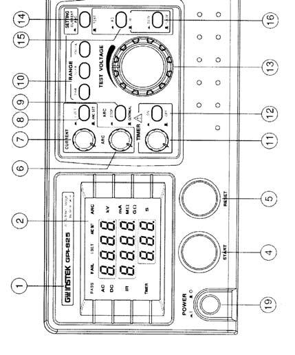
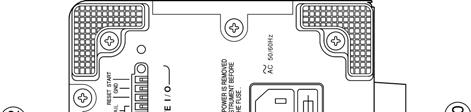
8 4. PANEL INTRODUCTION Front Panel Rear Panel 9 10
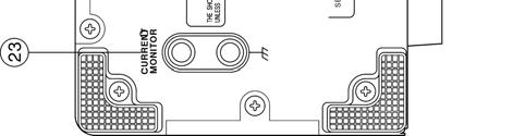
9 4-1. Front Panel 1 Model Number Model number and description 2. Display Indicate all messages about test procedure. 3. CAUTION Indicator LED During test the red LED will flash to indicate dangerous. 4. START Button Press the green button to start a test procedure. 5. RESET Button Press the red button to reset/stop a test procedure. 6. ARC VR Control ARC range. 7. Current VR Control the range of Cut-off current. 8. I Set/ARC Set : I Set, : ARC Set 9. ARC Con./Stop : A signal for stop test. when the ARC is in use, the test will be stopped. : A signal for continuous test. 10. Range Switch over the range. 11. Time VR Control test time. 12. TIMER ON/OFF : Power on and the test time can be adjusted. : Power off and the test time can not be adjusted. 13. Test Voltage Test voltage adjustment. 14. Setting (Current, ARC, & Test) : Can adjust Current/ARC VR to set current and ARC. : Stand by status for testing. 15. AC/DC or AC/IR : AC withstand voltage test. : DC withstand voltage test (only for GPT-815) or Insulation Test (only for GPI-825/826) V/1000V : 500V, : 1000V(for GPI-825/826 only) 17. High Voltage Output High voltage output terminal Seat 18. RETURN terminal The test return terminal. 19. Power switch Power on to start test Rear Panel 20. Fuse Holder with Voltage Selector To change AC source voltage, pull the fuse holder and replace with an adequate fuse to connect with AC power cord. 21. Ground Terminal Connect Ground terminal to the earth ground. 22. Remote I/O Control Remote I/O output joint point: Test signal: Two test holes has to be shorted when getting into test mode by pressing Start key, and it won t return to open status until the test result of PASS or FAIL comes available, or the RESET key is pressed. PASS signal: At the time when the test result comes out to be PASS, two PASS holes has to be shorted, and return to open until the RESET key is pressed. FAIL signal: At the time when the test result comes out to be FAIL, two FAIL holes has to be shorted, and return to open until the RESET key is pressed. RESET: The function is same as the RESET key on the front panel. START: The function is same as the START key on the front panel. 23. Current Monitor The cutoff current can be directly monitored by disconnecting the shorting bar from these terminals and connecting a milliammeter (DC/AC) between them. The milliammeter should be capable of measuring the cutoff current. Be sure to connect the shorting bar when no milliammeter is connected between these terminals
10 5. OPERATION 5-1. AC Withstanding Test Take GPT-805 as example, if want to output 5000VAC, set the cutoff current to 100mA and ARC to 50mA. During the 60s test time, the instrument will keep on testing even when the ARC appears. 1) Connect the Withstanding/Insulation Tester to the ground. 2) Adjust the Voltage Knob counter-clockwise to the lowest voltage position. 3) Set power switch to ON position. 4) Set CURRENT/ARC to position. 5) Set Range to 100mA range. 6) Set to I Set position by pressing (8) key, then adjust the Current VR until the value of is displayed on the panel. 7) Set to ARC Set by pressing (8) key, then adjust ARC VR until the value of 50.0 is displayed on the panel. 8) Set to Test by pressing (14) key. 9) Set Timer to ON position, adjust the knob until the timer value is at 60s. 10) Connect a test lead from the Return terminal (18) to the EUT (equipment under test). 11) Connect a red high pot probe from High voltage output terminal (17) to the EUT (equipment under test). 12) Press START key once to appear STBY(Stand by) on the display, then adjust (13) the voltage knob until the value of 5.00 is display on the panel. 13) Then, press START key to proceed testing, during testing, the warning indicator(3) will be flashing continuously. 14) If the value displayed on the panel drops because of the load adding test, adjust Voltage knob to maintain the value at ) If the test on the EUT is approval, the PASS indicator on the panel will be lighted up. 16) If the test on the EUT is disapproval, the FAIL indicator on the panel will be lighted up and the buzzer will blare out a warning. Now remove the high pot probe from the EUT, and press RESET to turn off the buzzer and FAIL light, then the instrument will be back to the initial status DC Withstanding Test Take GPT-815 as example, if want to output 5000VDC, set the cutoff current to 10mA and ARC to 10mA. During the 180s test time, the instrument will stop testing when the ARC appears. 1) Connect the Withstanding/Insulation Tester to the ground. 2) Adjust the Voltage Knob counter-clockwise to the lowest voltage position. 3) Set power switch to ON position. 4) Set the key (15) to DC position. 5) Set CURRENT/ARC of SETTING to position. 6) Set Range to 10mA range. 7) Set to I Set position by pressing (8) key, then adjust the Current VR until the value of 10.0 is displayed on the panel. 8) Set to ARC Set by pressing (8) key, then adjust ARC VR until the value of 10.0 is displayed on the panel. 9) Set to Test by pressing (14) key. 10) Set Timer to ON position, adjust the knob until the timer value is at 180s. 11) Connect a test lead from the Return terminal (18) to the EUT 13 14
11 (equipment under test). 12) Connect a red high pot probe from High voltage output terminal (17) to the EUT (equipment under test). 13) Press START key once to appear STBY (Stand by) on the display, then adjust (13) the voltage knob until the value of 5.00 is display on the panel. 14) Then, press START key to proceed testing, during testing, the warning indicator (3) will be flashing continuously. 15) If the value displayed on the panel drops because of the load adding test, adjust Voltage knob (13) to maintain the value at ) If the test on the EUT is approval, the PASS indicator on the panel will be lighted up. 17) During testing, if the ARC is occurred, both the lights of ARC and FAIL will be on, and the buzzer will blare out a warning, now remove the high pot probe from the EUT, and press RESET to turn off the buzzer, ARC and FAIL lights, then the instrument will be back to the initial status. 18) If the test is over the jump-out current, the FAIL indicator on the panel will be lighted up and the buzzer will blare out a warning. Now remove the high pot probe from the EUT, and press RESET to turn off the buzzer and FAIL light, then the instrument will be back to the initial status Insulation Test Take GPT-825 as example, set output to 1000V, but without specifying the test time. 1) Connect the Withstanding/Insulation Tester to the ground. 2) Adjust the Voltage Knob counter-clockwise to the lowest voltage position. 3) Set power switch to ON position. 4) Set the key (15) to IR position. 5) Set the Timer to OFF position. 6) Connect a test lead from the Return terminal (18) to the EUT (equipment under test). 7) Connect a red high pot probe from High voltage output terminal (17) to the EUT (equipment under test). 8) Press START key once to appear STBY (Stand by) on the display, then, press START key to proceed testing. During testing, the warning indicator (3) will be flashing continuously. 9) If the insulation resistance of the EUT is within 2000MΩ, thus the panel will display the insulation resistance value of the EUT, and the testing is kept going until the RESET key is pressed. 10) If the test on the EUT is disapproval, the FAIL indicator on the panel will be lighted up and the buzzer will blare out a warning. Now remove the high pot probe from the EUT, and press RESET to turn off the buzzer and FAIL light, then the instrument will be back to the initial status
12 6. MAINTENANCE The following instructions are used by qualified person only to avoid electrical shock, do not perform any service other than contained in the operation instructions unless you are qualified to do so Fuse Rating and type If the fuse blows, the product will not operate. Try to determine and correct the cause of the blown fuse, then replace the fuse with correct rating and type shown as below: WARNING: For continued fire protection, replace only with 250V fuse of the specified type and rating, and disconnect the power cord before proceeding fuse replacement Cleaning To keep the instrument clean, wipe the case with a damp cloth and detergent. Do not use abrasives or solvents. 17
Declaration of Conformity
 We Declaration of Conformity GOOD WILL INSTRUMENT CO., LTD. No. 7-1, Jhongsing Rd, Tucheng City, Taipei County 236, Taiwan GOOD WILL INSTRUMENT (SUZHOU) CO., LTD. No.69 Lushan Road, Suzhou New District
DC POWER SUPPLY ALIMENTATION C.C.
 DC POWER SUPPLY ALIMENTATION C.C. ISO-TECH IPS 303A 201-3424 ISO-TECH IPS 601A 201-3446 SAFETY TERMS AND SYMBOLS These terms may appear in this manual or on the product: WARNING. Warning statements identify
ISO-TECH IPS1810H and IPS1603D DC power supply ISO-TECH IPS 1810H et IPS 1603D Alimentation électrique c.c.
 ISO-TECH IPS1810H and IPS1603D DC power supply ISO-TECH IPS 1810H et IPS 1603D Alimentation électrique c.c. ISO-TECH IPS 1810H 204-713 ISO-TECH IPS 1603D 204-729 82IP-1810HME Ei Statement of Compliance
SAFETY TERMS AND SYMBOLS
 SAFETY TERMS AND SYMBOLS These terms may appear in this manual or on the product: WARNING. Warning statements identify condition or practices that could result in injury or loss of life. CAUTION. Caution
DC POWER SUPPLY (Switching mode)
") DC POWER SUPPLY (Switching mode) ISO-TECH IPS1820D RS Stock No. 357-0760 ISO-TECH IPS3610D RS Stock No. 357-0776 ISO-TECH IPS606D RS Stock No. 357-0782 82IP-3610DMB Ei SAFETY TERMS AND SYMBOLS These terms
DC POWER SUPPLY (Switching mode) ISO-TECH IPS1820D RS Stock No. 357-0760 ISO-TECH IPS3610D RS Stock No. 357-0776 ISO-TECH IPS606D RS Stock No. 357-0782 82IP-3610DMB Ei SAFETY TERMS AND SYMBOLS These terms
MAX. AC 600V HOLD V M H.V. LIVE CIRCUIT DIGITAL INSULATION TESTER DO NOT OPERATE IF LIT POWER DATA HOLD TEST ON / OFF 250V 500V 1000V OFF CAT.
 INSULATION TESTER EARTH MAX. AC 600V LINE AC -+ HOLD V k M LIVE CIRCUIT DIGITAL INSULATION TESTER DO NOT OPERATE IF LIT M H.V. POWER DATA HOLD TEST ON / OFF 250V 500V 1000V ACV OFF 0 CAT.III 600V INSTRUCTION
Declaration of Conformity
 Declaration of Conformity We GOOD WILL INSTRUMENT CO., LTD. No. 95-11, Pao-Chung Rd., Hsin-Tien City, Taipei Hsien, Taiwan GOOD WILL INSTRUMENT (SUZHOU) CO., LTD. No.69 Lushan Road, Suzhou New District
& HIGH CURRENT DC POWER SUPPLIES INSTRUCTION MANUAL
 72-6850 & 72-6852 HIGH CURRENT DC POWER SUPPLIES INSTRUCTION MANUAL Table of Contents Introduction 2 Specification 2 Safety 4 EMC 5 Installation 6 Connections 6 Operation 7 Maintenance and Repair 8 www.tenma.com
Mini Multimeter with Non-Contact Voltage Detector (NCV)
") Owner s Manual Mini Multimeter with Non-Contact Voltage Detector (NCV) Model No. 82314 CAUTION: Read, understand and follow Safety Rules and Operating Instructions in this manual before using this product.
Owner s Manual Mini Multimeter with Non-Contact Voltage Detector (NCV) Model No. 82314 CAUTION: Read, understand and follow Safety Rules and Operating Instructions in this manual before using this product.
USER MANUAL. Insulation Tester + DMM. Model MG320
 USER MANUAL Insulation Tester + DMM Model MG320 Table of Contents 1. INTRODUCTION 3 2. SAFETY 3 3. METER DESCRIPTION 5 4. CONTROL BUTTONS 6 5. SYMBOLS AND ANNUNCIATORS 6 6. OPERATING INSTRUCTIONS 7 6.1
PRM-4. Phase Sequence and Motor Rotation Tester. Users Manual. For detailed specifications and ordering info go to
 PRM-4 Phase Sequence and Motor Rotation Tester Users Manual For detailed specifications and ordering info go to www.testequipmentdepot.com PRM-4 Phase Sequence and Motor Rotation Tester English Users Manual
Autoranging Industrial Multimeter
 Owner's Manual Autoranging Industrial Multimeter Model No. 82005 CAUTION: Read, understand and follow Safety Rules and Operating Instructions in this manual before using this product. Safety Operation
Autoranging Multimeter
 Owner's Manual Autoranging Multimeter Model No. 82334 CAUTION: Read, understand and follow Safety Rules and Operating Instructions in this manual before using this product. Safety Operation Maintenance
Table of Contents. Title Page UT501/UT502 OPERATING MANUAL. Introduction. Unpacking the Meter. Safety Information. International Electrical Symbols
 Table of Contents Title Page Introduction Unpacking the Meter Safety Information International Electrical Symbols The Meter Structure Key Functions Rotary Switch Measurement Operation A. Measuring Voltages
1.Safe testing IMPORTANT:
 Electricity is dangerous and can cause injury and death. Always treat it with the greatest of respect and care. If you are not quite sure how to proceed, then stop, take advice from a qualified person.
True RMS Autoranging Multimeter
 Owner's Manual True RMS Autoranging Multimeter Model No. 73754 CAUTION: Read, understand and follow Safety Rules and Operating Instructions in this manual before using this product. Safety Operation Maintenance
Rental Industry Safety Tester Safe Check 5s
 Rental Industry Safety Tester Safe Check 5s Feb 2006 2006 Clare Instruments Inc. Issue 2.0 Firmware Version : 1.2a Limited Warranty & Limitation of Liability Clare Instruments Inc, guarantees this product
MM300. INSTRUCTION MANUAL Manual-Ranging Digital Multimeter
 INSTRUCTION MANUAL Manual-Ranging Digital Multimeter MM300 DATA HOLD AUDIBLE CONTINUITY BATTERY TEST DIODE TEST 10A 2MΩ ESPAÑOL pg. 13 FRANÇAIS pg. 25 MM300-1390109ART.indd 1 9/21/2015 2:48:00 PM GENERAL
User's Manual. High Voltage Megohmmeter. Analog Insulation Tester plus AC Voltage and Continuity Tests. Model
 User's Manual High Voltage Megohmmeter Analog Insulation Tester plus AC Voltage and Continuity Tests Model 380353 Warranty EXTECH INSTRUMENTS CORPORATION warrants this instrument to be free of defects
362 Clamp Meter. Users Manual
 362 Clamp Meter Users Manual PN 3622678 August 2010, Rev. 1, 4/13 2010, 2013 Fluke Corporation. All rights reserved. Printed in China. Specifications are subject to change without notice. All product names
Switching DC Power Supply
 99 Washington Street Melrose, MA 02176 Phone 781-665-1400 Toll Free 1-800-517-8431 Visit us at www.testequipmentdepot.com Model 1693, 1694 Switching DC Power Supply INSTRUCTION MANUAL 1 Safety Summary
DUAL 60V 20A POWER FLEX POWER SUPPLY INSTRUCTION MANUAL
 72-7570 DUAL 60V 20A POWER FLEX POWER SUPPLY INSTRUCTION MANUAL Table of Contents Specification 1 Safety 3 EMC 4 Installation 5 Connections 5 Operation 6 Maintenance 8 Specification General specifications
User s Manual Power Supply IM E. 5th Edition
 User s Manual 700938 Power Supply 5th Edition Thank you for purchasing the 700938 Power Supply. This user s manual contains useful information about the instrument s functions and operating procedures
RS-3 PRO RS-1007 PRO. CAT IV Analog Clamp meter Series. Users Manual. For detailed specifications and ordering info go to
 RS-3 PRO RS-1007 PRO CAT IV Analog Clamp meter Series Users Manual For detailed specifications and ordering info go to www.testequipmentdepot.com RS-3 PRO RS-1007 PRO CAT IV Analog Clampmeter Series English
1662/1663/1664 FC. Electrical Installation Tester. Safety Information. Warnings
 1662/1663/1664 FC Electrical Installation Tester Safety Information Go to www.fluke.com to register your Product and find more information. A Warning identifies conditions and procedures that are dangerous
MOdel No: MM19.V3 WARNING CAUTION 1. SAFETY INSTRUCTIONS
 Instructions for: Digital Multimeter - 6 Function MOdel No: MM19.V3 Thank you for purchasing a Sealey product. Manufactured to a high standard this product will, if used according to these instructions
Non-Contact Phase Rotation Tester
 User's Guide 99 Washington Street Melrose, MA 076 Phone 78-665-400 Toll Free -800-57-84 Visit us at www.testequipmentdepot.com Non-Contact Phase Rotation Tester Model PRT00 Introduction Congratulations
Model Insulation Tester / Megohmmeter. User Manual
 Model 380363 Insulation Tester / Megohmmeter User Manual Introduction Congratulations on your purchase of Extech s Insulation Tester/Megohmmeter. The Model 380363 provides three test ranges plus continuity
User's Manual Digital High Voltage Insulation Tester Model
 99 Washington Street Melrose, MA 02176 Phone 781-665-1400 Toll Free 1-800-517-8431 Visit us at www.testequipmentdepot.com Back to the Extech 380375 Product Page User's Manual Digital High Voltage Insulation
INSTRUCTION MANUAL PORTABLE APPLIANCE TESTER
 INSTRUCTION MANUAL PORTABLE APPLIANCE TESTER KEW6201A CONTENTS 1. Safe testing 1 2. Procedure of removing cover. 3 2.1 Method of removing the cover. 3 2.2 Method of storing the cover. 3 3. Product summary
OPERATING INSTRUCTION
 11/05 Form #271 99 Washington Street Melrose, MA 02176 Phone 781-665-1400 Toll Free 1-800-517-8431 OPERATING INSTRUCTION Visit us at www.testequipmentdepot.com MODEL 3132 ANALOG INSULATION-CONTINUITY TESTER
Triple Output Power Supply
 Test Equipment Depot - 800.517.8431-99 Washington Street Melrose, MA 02176 TestEquipmentDepot.com Model 1672, 1673 Triple Output Power Supply INSTRUCTION MANUAL 1 Safety Summary The following safety precautions
User s Manual Power Supply. IM E 3rd Edition. Yokogawa Electric Corporation
 User s Manual 700938 Power Supply Yokogawa Electric Corporation 3rd Edition Introduction Revisions Thank you for purchasing the 700938 Power Supply. This Instruction Manual contains useful information
Mini Multimeter with Non-Contact Voltage Detector (NCV)
") Owner s Manual Mini Multimeter with Non-Contact Voltage Detector (NCV) Model No. 82315 REL CAUTION: Read, understand and follow Safety Rules and Operating Instructions in this manual before using this
Owner s Manual Mini Multimeter with Non-Contact Voltage Detector (NCV) Model No. 82315 REL CAUTION: Read, understand and follow Safety Rules and Operating Instructions in this manual before using this
80 Series V Digital Multimeter Safety Information
 80 Series V Digital Multimeter Safety Information Limited Lifetime Warranty. See the Users Manual for the full warranty. Go to www.fluke.com to register your product and find more information. A Warning
Non-Contact Phase Rotation Tester
 USER GUIDE Non-Contact Phase Rotation Tester Model PRT00 Model PRT00-M Introduction Congratulations on your purchase of this Extech Meter. The PRT00 is used to quickly and accurately determine three phase
Users Manual. Phase Rotation Indicator
 9040 Phase Rotation Indicator Users Manual PN 2438546 April 2005, Rev.2, 5/11 2005-2011 Fluke Corporation. All rights reserved. Specifications are subject to change without notice. All product names are
Megohmmeter Test Probe
 Megohmmeter Test Probe User Manual ENGLISH www.aemc.com CHAUVIN ARNOUX GROUP Copyright Chauvin Arnoux, Inc. d.b.a. AEMC Instruments. All rights reserved. No part of this documentation may be reproduced
EPS/ELA-Series User Manual EPS/ELA 250W
 EPS/ELA-Series User Manual EPS/ELA 250W EPS Stromversorgung GmbH Tel: +49 (0)821 570451 0 Index 3 Page: 1 Table of contents: Page 1. Features of ELA-Series... 3 1.1 Basic Functions... 3 1.2 Options...
i3000s/i2000 Flex AC Current Probe
 i3000s/ AC Current Probe Instruction Sheet Introduction The i3000s 24 Flex, i3000s 36 Flex, and AC Current Probes (the Probe) are used with oscilloscopes, digital multimeters, recorders or data loggers.
User s Manual Power Supply. IM E 2nd Edition. Yokogawa Electric Corporation
 User s Manual 701934 Power Supply Yokogawa Electric Corporation 2nd Edition Foreword Revisions Thank you for purchasing the 701934 Power Supply. This user's manual contains useful information about the
0.5 s to 30 h (30 s, 3 min, 30 min, 3 h, 30 h)
") Mechatronic Analog Timer H3AM Please read and understand this catalog before purchasing the products. Please consult your OMRON representative if you have any questions or comments. Refer to Warranty and
Mechatronic Analog Timer H3AM Please read and understand this catalog before purchasing the products. Please consult your OMRON representative if you have any questions or comments. Refer to Warranty and
RE48AML12MW time delay relay 2 functions s..300 h V AC - 2 OC
 Characteristics time delay relay 2 functions - 0.02 s..300 h - 24..240 V AC - 2 OC Complementary Product front plate size Control type Housing material Main Range of product Product or component type Electrical
INSTRUCTION MANUAL IDM93N DIGITAL MULTIMETER EN FR IT DE
 INSTRUCTION MANUAL IDM93N DIGITAL MULTIMETER EN FR IT DE ISO-TECH IDM93N DIGITAL MULTIMETER INSTRUCTION MANUAL 1 2 WARNING THE SERVICING INSTRUCTIONS DESCRIBED WITHIN THIS MANUAL ARE FOR USE BY QUALIFIED
POWERED BY KT71 / Portable Appliance Tester. Instruction Manual
 KT71 / Portable Appliance Tester POWERED BY Instruction Manual CONTENTS 1. Safe testing 1 2. Procedure of removing cover.. 3 2.1 Method of removing the cover... 3 2.2 Method of storing the cover... 3 3.
RE48AML12MW time delay relay 2 functions s..300 h V AC - 2 OC
 Characteristics time delay relay 2 functions - 0.02 s..300 h - 24..240 V AC - 2 OC Main Range of product Product or component type Electrical connection Discrete output type Contacts type and composition
2-Year Limited Warranty. See the Users Manual for the full warranty.
 1732/1734 Energy Logger Safety Information 2-Year Limited Warranty. See the Users Manual for the full warranty. Go to www.fluke.com to register your Product and find more information. A Warning identifies
MY /2-DIGIT DIGITAL MULTIMETER Users Manual
 MY-65 4 1/2-DIGIT DIGITAL MULTIMETER Users Manual Read the Users Manual thoroughly before use. WARRANTY This instrument is warranted to be free from defects in material and workmanship for a period of
Metrohm E3640 FLASH TESTER INSTRUCTION MANUAL. Martindale Electric Co Ltd.
 Metrohm Martindale Electric Metrohm House, Imperial Park, Imperial Way, Watford, Hertfordshire, WD24 4PP, UK T: 01923 441717 F: 01923 446900 Email: sales@martindale-electric.co.uk web: www.martindale-electric.co.uk
Instruction manual. High voltage insulation resistance tester KEW3121B/3122B
 Instruction manual High voltage insulation resistance tester KEW3121B/3122B Contents 1. Safety warnings... 1 2. Features... 5 3. Specification... 6 4. Instrument layout... 9 5. Getting started... 10 5-1
User Guide. Model Insulation Tester / Megohmmeter
 User Guide Model 380260 Insulation Tester / Megohmmeter Introduction Congratulations on your purchase of Extech s Insulation Tester/Megohmmeter. The Model 380260 provides three test ranges plus continuity
Instruction Manual. 99 Washington Street Melrose, MA Fax TestEquipmentDepot.com. Model 308A Digital Insulation & Continuity Meter
 Instruction Manual 99 Washington Street Melrose, MA 02176 Fax 781-665-0780 TestEquipmentDepot.com Model 308A Digital Insulation & Continuity Meter INDEX PAGE INSTRUMENT LAYOUT... 1 INTRODUCTION... 2 SAFETY
USER MANUAL. 200A AC Mini Clamp Meter. Model MA130. Please visit for user manual translations
 USER MANUAL 200A AC Mini Clamp Meter Model MA130 Please visit www.extech.com for user manual translations Introduction Thank you for selecting the Extech Instruments 200A AC Mini Clamp Meter. The MA130
TES-1601 INSTRUCTION MANUAL AUTORANGING INSULATION TESTER SAFETY INFORMATION TES ELECTRICAL ELECTRONIC CORP. Warnings and Safety symbols:
 TES-1601 AUTORANGING INSULATION TESTER INSTRUCTION MANUAL SAFETY INFORMATION The circuit under test must be de-energized and isolated before connections are made except for voltage measurement. Circuit
Instruction Manual. Vortex Mixers
 Instruction Manual Vortex Mixers TABLE OF CONTENTS Package Contents............... 1 Warranty............... 1 Installation............... 2 Maintenance & Servicing............... 2 Environmental Conditions...............
90W DC Power Supply. User Manual. 99 Washington Street Melrose, MA Phone Toll Free
 99 Washington Street Melrose, MA 02176 Phone 781-665-1400 Toll Free 1-800-517-8431 Visit us at www.testequipmentdepot.com 1410 90W DC Power Supply User Manual Safety Summary The following safety precautions
INSTRUCTION MANUAL MARTINDALE CM52 CLAMP METER. ELECTRIC Trusted by professionals. Other products from Martindale:
 Other products from Martindale: 18th Edition Testers All-in-one s Calibration Equipment Continuity Testers Electrician s Kits Full Calibration & Repair Service Fuse Finders Digital Clamp Meters Digital
INSTRUCTION MANUAL ANALOGUE INSULATION TESTER KEW 3131M KYORITSU ELECTRICAL INSTRUMENTS WORKS,LTD., TOKYO JAPAN
 INSTRUCTION MANUAL ANALOGUE INSULATION TESTER KEW 3131M KYORITSU ELECTRICAL INSTRUMENTS WORKS,LTD., TOKYO JAPAN Contents 1. Safety Precautions... 1 2. Features... 3 3. Specifications... 4 4. Instrument
EZYPAT / EZYPAT+ / SMARTPAT PORTABLE APPLIANCE TESTER INSTRUCTION MANUAL
 EZYPAT / EZYPAT+ / SMARTPAT PORTABLE APPLIANCE TESTER INSTRUCTION MANUAL CONTENTS 1. Safe testing... 2 2. Product summary and explanation... 5 2.1 Product summary... 5 2.2 Test Function... 5 2.3 Features...
PHASE ROTATION INDICATOR with OPEN PHASE CHECKER
 99 Washington Street Melrose, MA 02176 Phone 781-665-1400 Toll Free 1-800-517-8431 Visit us at www.testequipmentdepot.com BST-PR10 PHASE ROTATION INDICATOR with OPEN PHASE CHECKER INSTRUCTION MANUAL DESIGNATIONS
MARTINDALE INSTRUCTIONS ELITE FUSE FINDER KIT ELECTRIC. Trusted by professionals. 4.4 Storage Conditions
 4.4 Storage Conditions The FD650/R and FD500/T or FD600/T should be kept in warm dry conditions away from direct sources of heat or sunlight, with the battery removed and in such a manner as to preserve
OPERATING INSTRUCTION
 99 Washington Street Melrose, MA 02176 Phone 781-665-1400 Toll Free 1-800-517-8431 Visit us at www.testequipmentdepot.com 8/05 Form #270 OPERATING INSTRUCTION MODEL 3005 DIGITAL INSULATION-CONTINUITY TESTER
99 Washington Street Melrose, MA Fax TestEquipmentDepot.com. Instruction Manual. Model 2831D 4 ½ Digit True RMS Digital Multimeter
 99 Washington Street Melrose, MA 02176 Fax 781-665-0780 TestEquipmentDepot.com Instruction Manual Model 2831D 4 ½ Digit True RMS Digital Multimeter 1 1. PRODUCT DESCRIPTION 1-1. Introduction Thank you
1587 FC/1587/1577. Insulation Multimeter. Safety Information. Warnings
 1587 FC/1587/1577 Insulation Multimeter Safety Information Go to www.fluke.com to register your Product and find more information. A Warning identifies conditions and procedures that are dangerous to the
Safety design conforming to the following provisions
 Safety design conforming to the following provisions of IEC61010. Overvoltage category III 300V, pollution degree 2, Overvoltage category II 600V, pollution degree 2, Data hold switch for easy reading
Advanced Test Equipment Rentals ATEC (2832)
") Established 1981 Advanced Test Equipment Rentals www.atecorp.com 800-404-ATEC (2832) Digital Ground Resistance Tester Model 4610 & 4610 Kits 99 Washington Street Melrose, MA 02176 Fax 781-665-0780 TestEquipmentDepot.com
Established 1981 Advanced Test Equipment Rentals www.atecorp.com 800-404-ATEC (2832) Digital Ground Resistance Tester Model 4610 & 4610 Kits 99 Washington Street Melrose, MA 02176 Fax 781-665-0780 TestEquipmentDepot.com
BM kv Digital Insulation Tester USER MANUAL
 M BM5200 5 kv Digital Insulation Tester USER MANUAL CONTENTS Safety warnings...3 Symbols used on instrument...4 Cleaning...4 General description...5 Insulation resistance test modes...5 Automatic discharge...5
LH41A. User Manual. Clamp On Ammeter. For detailed specifications and ordering info go to
 LH41A Clamp On Ammeter User Manual For detailed specifications and ordering info go to www.testequipmentdepot.com LH41A Clamp On Ammeter Users Manual English April 2007, Rev.2 2007 Amprobe Test Tools.
KEWTECH. KT56 digital multi function tester. Instruction manual
 KEWTECH KT56 digital multi function tester Instruction manual Contents 1 Safety Notice 1 2 Features and Principles of Measurement 3 3 Introduction 6 4 Specifications 7 5 Instrument layout 9 6 Operating
AC/DC CURRENT TRANSDUCER INSTRUCTION MANUAL
 AC/DC CURRENT TRANSDUCER INSTRUCTION MANUAL INTRODUCTION 1-1 Unpacking and Inspection Upon removing your new Clamp Meter from its packing, you should have the following items: 1. Current Transducer with
BENCHTOP INSTRUMENT. Single Channel DC Power Supply SL Series Operation Manual V1.0
 BENCHTOP INSTRUMENT Single Channel DC Power Supply SL Series Operation Manual V1.0 CONTENTS 1. INTRODUCTION... - 1-2. PRODUCTION MODELS... - 1-3. SPECIFICATIONS... - 2-4. PANEL CONTROLS AND INDICATORS...
Safety Precautions. Damages resulting from failure to observe these safety precautions are exempt from any legal claims whatever.
 Safety Precautions This product complies with the requirements of the following European Community Directives: 2004/108/EC (Electromagnetic Compatibility) and 2006/95/EC (Low Voltage) as amended by 2004/22/EC
Model ST Instruction Manual. Digital Insulation Tester. reedinstruments. www. com
 Model ST-5500 Digital Insulation Tester Instruction Manual reedinstruments com Table of Contents Safety... 3 Specifications...4-5 General... 4 Electrical... 5 Meter Description... 6 Operating Instructions...6-7
Date received into service; / /.
 Innovating Together RIGEL SafeTest 50 electrical safety analyzer Copyright 2016 SEAWARD GROUP Last Update: April 20th 2016 Instruction Manual 410A570 Revision 1.2 Limited Warranty & Limitation of Liability
DIGITAL RCD(ELCB) TESTER
 TESTER") INSTRUCTION MANUAL DIGITAL RCD(ELCB) TESTER KEW 5410 R KYORITSU ELECTRICAL INSTRUMENTS WORKS, LTD. Contents 1. Safety Warnings.... 1 2. Procedure of removing Cover. 3 2-1 Method of removing the Cover.
INSTRUCTION MANUAL DIGITAL RCD(ELCB) TESTER KEW 5410 R KYORITSU ELECTRICAL INSTRUMENTS WORKS, LTD. Contents 1. Safety Warnings.... 1 2. Procedure of removing Cover. 3 2-1 Method of removing the Cover.
12 amp RMS Battery Charger
 12 amp RMS Battery Charger 83-5000-12 If faults cannot be remedied, contact the Helpline on 020 8391 6767 helpline@hilka.co.uk Manufactured under license by Hilka Pro Imports GUARANTEE This product is
362 Clamp Meter. Users Manual
 362 Clamp Meter Users Manual PN 3622678 August 2010 2010 Fluke Corporation. All rights reserved. Printed in China. Specifications are subject to change without notice. All product names are trademarks
PRO POWER 2 0 A L I T H I U M B AT T E RY C H A R G E R M O D E L : P P - L B C V E R S I O N : V 1. 0
 PRO POWER 2 0 A L I T H I U M B AT T E RY C H AR G E R M O D E L : P P - L B C - 1 2 2 0 V E R S I O N : V 1. 0 Contents 1. Revised History... 1 2. Warning... 1 3. Notes... 1 4. Product Number System...
Users Manual. Accessories Motor and Phase Rotation Indicator ships with the following items: 3 test leads 3 test probes 3 alligator clips 9 V battery
 MS5900 Users Manual Table of Contents Introduction Motor and Phase Rotation Indicator is a handheld, battery-operated instrument designed to detect the rotary field of three-phase systems and determine
BATTERY BOOSTER/CHARGER MODEL NO: DIGICAR 900
 BATTERY BOOSTER/CHARGER MODEL NO: DIGICAR 900 PART NO: 6261205 OPERATION & MAINTENANCE INSTRUCTIONS LS0715 INTRODUCTION Thank you for purchasing this CLARKE Battery booster / charger which is suitable
Safety design conforming to the following provisions
 Safety design conforming to the following provisions of IEC61010. Overvoltage category III 300V AC, pollution degree 2 Overvoltage category II 600V AC/DC, pollution degree 2 Protected throughout by double
RE-PR3-E-86&105 3-Phase Panel Mount 86 and 105kW
 Page 1 of 6 3-Phase Panel Mount 86 and 105kW Features: Benefits: 0-10Vdc, 0-5Vdc, 4-20mA or manual via potentiometer control input Over temperature protection with auto reset Enclosed panel mounting Efficient
OPERATING AND MAINTENANCE MANUAL. Primary Current Injection Test Set. 750ADM-H mk2
 OPERATING AND MAINTENANCE MANUAL Product: Type: Primary Current Injection Test Set 750ADM mk2 750ADM-H mk2 DESIGNED AND MANUFACTURED BY: T & R Test Equipment Limited 15-16 Woodbridge Meadows, Guildford,
Language specific user manuals are available on
 User Manual WEB Charger for LiFePO 4 Batteries EN User Manual Language specific user manuals are available on www.mascot.no/downloads/usermanuals Bruksanvisning Käyttöohjeet Bedienungsanleitung Mode d
BT508/BT510/BT520/BT521 Battery Analyzer Safety Sheet
 BT508/BT510/BT520/BT521 Battery Analyzer Safety Sheet Go to www.fluke.com to register your product, download manuals, and find more information. A Warning identifies conditions and procedures that are
Digital/Analog Megohmmeter Model 1026
 Digital/Analog Megohmmeter Model 1026 USER MANUAL 99 Washington Street Melrose, MA 02176 Phone 781-665-1400 Toll Free 1-800-517-8431 Visit us at www.testequipmentdepot.com Table of Contents Warning...3
Vol-Con XL (61-086) Voltage/Continuity Tester and Vol-Test (61-085) Voltage Tester Instruction Manual WARNING
 Voltage/Continuity Tester and Vol-Test (61-085) Voltage Tester Instruction Manual WARNING") Vol-Con XL (61-086) Voltage/Continuity Tester and Vol-Test (61-085) Voltage Tester Instruction Manual WARNING #61-085 #61-086 Read First: Safety Information This tester complies with UL3111-1, Cat III-600
Vol-Con XL (61-086) Voltage/Continuity Tester and Vol-Test (61-085) Voltage Tester Instruction Manual WARNING #61-085 #61-086 Read First: Safety Information This tester complies with UL3111-1, Cat III-600
Digital/Analog Megohmmeter Model 1026 USER MANUAL
 Digital/Analog Megohmmeter Model 1026 USER MANUAL Limited Warranty The Megohmmeter Model 1026, is warranted to the owner for a period of 2 years from the date of original purchase against defects in manufacture.
ASTROAI USER MANUAL DIGITAL MULTIMETER. NOTE: Fully read and understand this manual before using this instrument.
 ASTROAI USER MANUAL DIGITAL MULTIMETER NOTE: Fully read and understand this manual before using this instrument. WARNING: To avoid possible electric shock or personal injury, and to avoid possible damage
OPERATING INSTRUCTIONS
 OPERATING INSTRUCTIONS Digital Clamp Meter DSA500A IMPORTANT: RECEIVING INSTRUCTIONS Visually inspect all components for shipping damage. If you find damage, notify the carrier at once. Shipping damage
Chargestar P24 / P32 Battery Charger Startmaster P300 Starter / Charger
 Please dispose of packaging for the product in a responsible manner. It is suitable for recycling. Help to protect the environment, take the packaging to the local amenity tip and place into the appropriate
BATTERY BOOSTER/CHARGER MODEL NO: DIGICAR 600
 BATTERY BOOSTER/CHARGER MODEL NO: DIGICAR 600 PART NO: 6261200 OPERATION & MAINTENANCE INSTRUCTIONS LS0815 INTRODUCTION Thank you for purchasing this CLARKE Battery booster / charger which is suitable
SLA Battery Capacity Analyzer
 Model: 600B SLA Battery Capacity Analyzer USER MANUAL Safety Summary The following safety precautions apply to both operating and maintenance personnel and must be followed during all phases of operation,
Product Overview. Product Identification. Amps One CT Two CTs Three CTs
 AH06 (optional mounting bracket for small, medium, and large CTs) DANGER HAZARD OF ELECTRIC SHOCK, EXPLOSION, OR ARC FLASH Follow safe electrical work practices. See NFPA 70E in the USA, or applicable
1 This instrument must only be used by a competent and trained person and operated in strict accordance with the instructions.
 1 This instrument must only be used by a competent and trained person and operated in strict accordance with the instructions. KYORITSU will not accept liability for any damage or injury caused by misuse
Technical Information Manual
 Technical Information Manual Revision n. 4 18 June 2008 MOD. A3000NF 3-PHASE NOTCH FILTER MANUAL REV. 4 NPO: 00120/04:3000N.MUTx/04 CAEN will repair or replace any product within the guarantee period if
Table of Contents Title Page No.
 Table of Contents Title Page No. INTRODUCTION 1 SAFETY PRECAUTIONS / WARNINGS 2 CONTROLS AND INDICATORS 4 PREPARATION AND CAUTION BEFORE USE 5 TESTING PROCEDURES 6 A. AC/DC VOLTAGE MEASUREMENT 6 B. RESISTANCE
Rescue Pac. Please read and fully understand the instructions in this manual before operation. Keep this manual safe for future reference
 Please dispose of Packaging for the product in a responsible manner. It is suitable for recycling. Help to protect the environment, take the packaging to the local amenity tip and place into the appropriate
5 IN 1 JUMP START OPERATION & MAINTENANCE INSTRUCTIONS MODEL NO: JS5IN1 PART NO: LS0810
 5 IN 1 JUMP START MODEL NO: JS5IN1 PART NO: 6240005 OPERATION & MAINTENANCE INSTRUCTIONS LS0810 INTRODUCTION Thank you for purchasing this CLARKE product. Before attempting to use this product, please
User Guide. Model Insulation Tester / Megohmmeter
 User Guide Model 380260 Insulation Tester / Megohmmeter Introduction Congratulations on your purchase of Extech s Insulation Tester/Megohmmeter. The Model 380260 provides three test ranges plus continuity