TROUBLESHOOTING
|
|
|
- Barry Doyle
- 5 years ago
- Views:
Transcription
1 TROUBLESHOOTING
2 LAYOUT 1. Exhaust Manifold Assy 2. Exhaust Manifold Gasket 3. Hex Flange Nut 4. Heat Protector Assy 5. Hex Bolt (M6 X 1 X 25) 6. Heat Protector Assy 7. Hex Bolt (M8 X 1.25 X 16)
3 WCC Compl 2. Exhaust FRT Pipe Assy 3. UCC Compl 4. Muffler Complete?RR 5. Exhaust FRT Heat Protector 6. CTR Muffler Heat Protector 7. RR Muffler Heat Protector 8. Clamp 9. Gasket 10. Hanger 11. Hanger 12. Hanger 13. Nut 14. Nut 15. Bolt 16. Gasket Ring 19. Nut 20. CTR Muffler Complete
4 CAUTIONS Do not park the vehicle on flammable materials, such as grass, leaves and carpet. Do not touch the catalyst or the exhaust gas ignition system when the engine is running. If a misfire occurs in the combustion chamber or the emission of pollutant exceeds the specified level, the catalyst can be damaged. When servicing or replacing components of the exhaust system, makes sure that the components are positioned at regular intervals from all other parts of the under body. Be careful not to damage the exhaust system when lifting the vehicle from its side. All components and body parts of the engine exhaust system should be inspected for crack, damage, air hole, part loss and incorrect mounting location. Also check for any deformation which can result in exhaust gas drawn into the vehicle. Make sure that the exhaust pipe is cooled down sufficiently before working on it because it is still hot right after the engine is stopped. Wear protective gloves when removing the exhaust pipe.
5 OVERVIEW This system purifies the exhaust gas generated by the combustion in the engine to reduce the pollutants and noise during that arise during combustion. Harmful materials produced in the combustion process is treated and reduced in the exhaust system. Harmful materials discharged from the crankcase and fuel tank is drawn into the intake system again to reduce discharge amount of harmful materials. Emission aftertreatment system Catalytic Converter & O2 Sensor The catalytic converter is a monolith type purification system composed of cordierite which purifies exhaust gas through the small holes of active monolith catalyst from the exhaust manifold. As exhaust gas passes through the small holes in the layer in the middle, its CO and HC are reduced by oxidization reaction and its NOx is reduced by reduction reaction to Pt, Ph and Pd. The oxygen sensor sends signals for feedback and determination of catalyst condition. For detailed description, see the corresponding section. Purge Canister Control The fuel evaporative gas is a gas evaporated to the atmosphere in the section between the fuel tank and fuel line, and its main component is hydrocarbon (HC). The fuel evaporative gas is temporarily stored in the canister, and it is drawn to the engine through the throttle body when the purge control solenoid valve is open according to the engine operating condition. Blowby gas control system (crankcase ventilation system) Gas in the combustion chamber is sealed by the piston. However, gas is leaked through the gap between the cylinder and piston and drawn into the crankcase during the compression and explosion strokes. This gas is blowby gas and its main components are hydrocarbon and carbon monoxide. If this gas is drawn into the crankcase, the system can be corroded and oil can be deteriorated. Also, if this gas is discharged into the air, it can pollute the environment. To prevent these, the blowby gas reduction system (also called as crankcase ventilation system) draws the blowby gas from the crankcase to the combustion chamber for combustion.
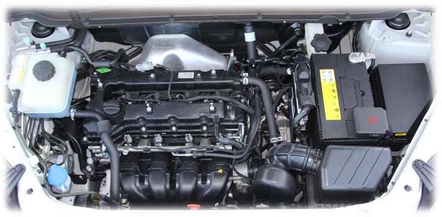
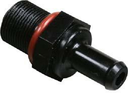
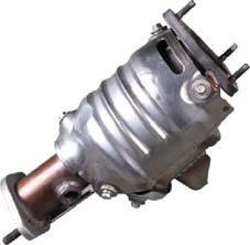
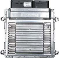
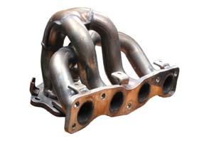
6 COMPONENTS WCC Engine ECU Engine CHECK lamp Exhaust manifold PCV valve Blowby hose

")


7 Exhaust No.1 Exhaust No.2 Exhaust No.3 (main muffler) Front oxygen sensor Rear oxygen sensor UCC
8 WORK FLOW IN EXHAUST SYSTEM
9 INPUT/OUTPUT DEVICES
ENGINE AND EMISSION CONTROL
 17-1 ENGINE AND EMISSION CONTROL CONTENTS ENGINE CONTROL SYSTEM........ 3 SERVICE SPECIFICATION............... 3 ON-VEHICLE SERVICE.................. 3 Accelerator Cable Check and Adjustment... 3 ACCELERATOR
EMISSION CONTROL (AUX. EMISSION CONTROL DEVICES) H6DO
 H6DO") EMISSION CONTROL (AUX. EMISSION CONTROL DEVICES) H6DO SYSTEM OVERVIEW 1. System Overview There are three emission control systems, which are as follows: Crankcase emission control system Exhaust emission
EMISSION CONTROL (AUX. EMISSION CONTROL DEVICES) H6DO SYSTEM OVERVIEW 1. System Overview There are three emission control systems, which are as follows: Crankcase emission control system Exhaust emission
EMISSION CONTROL (AUX. EMISSION CONTROL DEVICES) H4SO
 H4SO") EMISSION CONTROL (AUX. EMISSION CONTROL DEVICES) H4SO SYSTEM OVERVIEW 1. System Overview There are three emission control systems, which are as follows: Crankcase emission control system Exhaust emission
EMISSION CONTROL (AUX. EMISSION CONTROL DEVICES) H4SO SYSTEM OVERVIEW 1. System Overview There are three emission control systems, which are as follows: Crankcase emission control system Exhaust emission
EMISSION CONTROL (AUX. EMISSION CONTROL DEVICES) H4DOTC
 H4DOTC") EMISSION CONTROL (AUX. EMISSION CONTROL DEVICES) H4DOTC SYSTEM OVERVIEW 1. System Overview There are three emission control systems, which are as follows: Crankcase emission control system Exhaust emission
EMISSION CONTROL (AUX. EMISSION CONTROL DEVICES) H4DOTC SYSTEM OVERVIEW 1. System Overview There are three emission control systems, which are as follows: Crankcase emission control system Exhaust emission
EMISSION CONTROL SYSTEMS (2JZ GE) SYSTEM PURPOSE
 SYSTEM PURPOSE") SYSTEM PURPOSE The emission control systems are installed to reduce the amount of CO, HC and NOx exhausted from the engine ((3), (4) and (5)), to prevent the atmospheric release of blowby gascontaining
SYSTEM PURPOSE The emission control systems are installed to reduce the amount of CO, HC and NOx exhausted from the engine ((3), (4) and (5)), to prevent the atmospheric release of blowby gascontaining
EXHAUST SYSTEM AND MUFFLER
 54 04 AND MUFFLER Tail pipe Muffler #1 Pipe DOC (Diesel Oxidation Catalyst) MUFFLER The muffler is located at the middle of the exhaust pipe and reduces the pulse noise and the tail pipe noise by eliminating
ENGINE AND EMISSION CONTROL
 -1 ENGINE CONTROL.......... GENERAL INFORMATION...... SERVICE SPECIFICATIONS..... ON-VEHICLE SERVICE......... ACCELERATOR CABLE CHECK AND ADJUSTMENT.................... ACCELERATOR CABLE AND PEDAL......................
ENGINE AND EMISSION CONTROL
 17-1 GROUP 17 ENGINE AND EMISSION CONTROL CONTENTS ENGINE CONTROL........... 17-3 GENERAL INFORMATION....... 17-3 SERVICE SPECIFICATIONS..... 17-3 ON-VEHICLE SERVICE.......... 17-3 ACCELERATOR CABLE CHECK
EMISSION CONTROL SYSTEMS
 EMISSION CONTROL SYSTEMS (3SFE) EMISSION CONTROL SYSTEMS EC1 EC2 EMISSION CONTROL SYSTEMS (3SFE) System Purpose System SYSTEM PURPOSE Abbreviation Purpose Positive crankcase ventilation Fuel evaporative
SVX +++ EMISSION CONTROL SYSTEM AND VACUUM FITTING 2-1 SUBARU
 EMSSON CONTROL SYSTEM AND VACUUM FTTNG 2-1 SUBARU SVX 1992 Page 1. System Application......................................................... 2 2. Schematic Drawing..........................................................
ENGINE AND EMISSION CONTROL
 17-1 GROUP 17 ENGINE AND EMISSION CONTROL CONTENTS ENGINE CONTROL.......... 17-3 GENERAL INFORMATION...... 17-3 SERVICE SPECIFICATIONS..... 17-3 TROUBLESHOOTING.......... 17-3 INTRODUCTION TO ENGINE CONTROL
ENGINE AND EMISSION CONTROL
 17-1 ENGINE AND EMISSION CONTROL CONTENTS EMISSION CONTROL SYSTEM... 2 GENERAL... 2 Outline of Changes... 2 GENERAL INFORMATION... 2 SERVICE SPECIFICATION... 2 VACUUM HOSE... 3 Vacuum Hose Piping Diagram...
Module 5: Emission Control for SI Engines Lecture20:ADD-ON SYSTEMS FOR CONTROL OF ENGINE-OUT EMISSIONS
 ADD-ON SYSTEMS FOR CONTROL OF ENGINE-OUT EMISSIONS The Lecture Contains: Crankcase Emission Control (PCV System) Evaporative Emission Control Exhaust Gas Recirculation Water Injection file:///c /...%20and%20Settings/iitkrana1/My%20Documents/Google%20Talk%20Received%20Files/engine_combustion/lecture20/20_1.htm[6/15/2012
Emission from gasoline powered vehicles are classified as 1. Exhaust emission 2. Crank case emission 3. Evaporative emission. Table 1.
 Introduction: Main three types of automotive vehicle being used 1. Passenger cars powered by four stroke gasoline engines 2. Motor cycles, scooters and auto rickshaws powered mostly by small two stroke
EMISSION CONTROL EMISSION CONTROLS
 EMISSION CONTROL EMISSION CONTROLS Emissions control systems on Land Rover vehicles work closely with fuel system controls to reduce airborne pollutants. Improper operation of these systems can lead to
ENGINE AND EMISSION CONTROL
 17-1 GROUP 17 ENGINE AND EMISSION CONTROL CONTENTS ENGINE CONTROL 17-2 GENERAL INFORMATION 17-2 AUTO-CRUISE CONTROL SYSTEM 17-3 GENERAL INFORMATION 17-3 CONSTRUCTION AND OPERATION 17-5 17-7 GENERAL INFORMATION
5. FUEL SYSTEM 5-0 FUEL SYSTEM MXU 250R/300R
 5 FUEL SYSTEM 5 SERVICE INFORMATION------------------------------------------------ 5-2 TROUBLESHOOTING----------------------------------------------------- 5-3 FUEL TANK -----------------------------------------------------------------
1. CAUTIONS. 1) Standard pattern of soot accumulation Normal Soot Combustion. Abnormal Soot Accumulation
 Standard pattern of soot accumulation Normal Soot Combustion. Abnormal Soot Accumulation") 241202 143 1. CAUTIONS 1) Standard pattern of soot accumulation Abnormal Soot Accumulation Normal Soot Combustion Cautions to protect the catalyst filter Use the designated fuel only. Observe the recommended
241202 143 1. CAUTIONS 1) Standard pattern of soot accumulation Abnormal Soot Accumulation Normal Soot Combustion Cautions to protect the catalyst filter Use the designated fuel only. Observe the recommended
EMISSION. ' Purge Control System Inspection CONTENTS CATALYTIC CONVERTER EVAPORATIVE EMISSION CANISTER...
 17-1 EMSSON CONTENTS 110007497. Evaporative CATALYTC CONVERTER... 22 General nformation... nspection... 23 Removal and nstallation... 23 EVAPORATVE EMSSON CANSTER... 24 nspection... 24 Removal and nstallation...
ENGINE AND EMISSION CONTROL
 17-1 GROUP 17 ENGINE AND EMISSION CONTROL CONTENTS ENGINE CONTROL.......... 17-3 GENERAL DESCRIPTION...... 17-3 ENGINE CONTROL SYSTEM DIAGNOSIS.................. 17-3 INTRODUCTION TO ENGINE CONTROL SYSTEM
Exhaust After-Treatment System. This information covers design and function of the Exhaust After-Treatment System (EATS) on the Volvo D16F engine.
 on the Volvo D16F engine.") Volvo Trucks North America Greensboro, NC USA DService Bulletin Trucks Date Group No. Page 1.2007 258 44 1(6) Exhaust After-Treatment System Design and Function D16F Exhaust After-Treatment System W2005772
Volvo Trucks North America Greensboro, NC USA DService Bulletin Trucks Date Group No. Page 1.2007 258 44 1(6) Exhaust After-Treatment System Design and Function D16F Exhaust After-Treatment System W2005772
ENGINE AND EMISSION CONTROL
 17-1 GROUP 17 ENGINE AND EMISSION CONTROL CONTENTS ENGINE CONTROL.......... 17-3 GENERAL DESCRIPTION...... 17-3 ENGINE CONTROL SYSTEM DIAGNOSIS.................. 17-3 INTRODUCTION TO ENGINE CONTROL SYSTEM
DOT Tire Quality Grading (U.S. Cars)
") DOT Tire Quality Grading (U.S. Cars) The tires on your car meet all U.S. Federal Safety Requirements. All tires are also graded for treadwear, traction, and temperature performance according to Department
DOT Tire Quality Grading (U.S. Cars) The tires on your car meet all U.S. Federal Safety Requirements. All tires are also graded for treadwear, traction, and temperature performance according to Department
1. SPECIFICATION Emission Regulation Front Area 158 X 124 X 78L. Size
 241202 143 1. SPECIFICATION Emission Regulation Front Area Size CDPF Canister CDPF EuroV 154.06cm2 DOC 158 X 124 X 78L DPF 158 X 124 X 254L Shell SUS430J1L X 1.5t End Cone SUS430J1L X 2.0t (Single) Catalyst
State of the Art (SOTA) Manual for Internal Combustion Engines
 Manual for Internal Combustion Engines") State of the Art (SOTA) Manual for Internal Combustion Engines July 1997 State of New Jersey Department of Environmental Protection Air Quality Permitting Program State of the Art (SOTA) Manual for Internal
State of the Art (SOTA) Manual for Internal Combustion Engines July 1997 State of New Jersey Department of Environmental Protection Air Quality Permitting Program State of the Art (SOTA) Manual for Internal
Engine Systems. Basic Engine Operation. Firing Order. Four Stroke Cycle. Overhead Valves - OHV. Engine Design. AUMT Engine Systems 4/4/11
 Advanced Introduction Brake to Automotive Systems Diagnosis Service and Service Basic Engine Operation Engine Systems Donald Jones Brookhaven College The internal combustion process consists of: admitting
UNDERSTANDING 5 GAS DIAGNOSIS
 UNDERSTANDING 5 GAS DIAGNOSIS AND EMISSIONS Gas Diagnostic Steps This procedure will help in your efforts to figure out what the five-gas reading are telling you. In order for five gas analyses to be conclusive
). The equipment that is used to limit these pollutants is commonly called emission control equipment.
. The equipment that is used to limit these pollutants is commonly called emission control equipment.") Стр. 1 из 51 EMISSION CONTROLS Introduction There are three sources of automotive pollutants: crankcase fumes, exhaust gases and gasoline evaporation. The pollutants formed from these substances can be
Стр. 1 из 51 EMISSION CONTROLS Introduction There are three sources of automotive pollutants: crankcase fumes, exhaust gases and gasoline evaporation. The pollutants formed from these substances can be
A L L Diagnostic Trouble Codes ( DTC ): P Code Charts General Information
: P Code Charts General Information") P0133 O2-Sensor Circuit Slow Response (Bank 1 / Sensor 1) - The linear O2 sensor is mounted on the front side of the Catalytic Converter (warm-up catalytic converter) or in the front exhaust pipe. It detects
P0133 O2-Sensor Circuit Slow Response (Bank 1 / Sensor 1) - The linear O2 sensor is mounted on the front side of the Catalytic Converter (warm-up catalytic converter) or in the front exhaust pipe. It detects
EMISSION CONTROL VISUAL INSPECTION PROCEDURES
 EMISSION CONTROL VISUAL INSPECTION PROCEDURES 1992 Infiniti G20 1983-98 GENERAL INFORMATION Emission Control Visual Inspection Procedures All Models * PLEASE READ THIS FIRST * This article is provided
5. FUEL SYSTEM 5-0 FUEL SYSTEM UXV 500
 5 FUEL SYSTEM 5 SERVICE INFORMATION------------------------------------------------ 5-02 TROUBLESHOOTING----------------------------------------------------- 5-03 FUEL TANK -----------------------------------------------------------------
ACCELERATOR CABLE AND PEDAL
 17 ENGINE & EMISSION CONTROL 1996 Engine Control System ACCELERATOR CABLE AND PEDAL REMOVAL AND INSTALLATION Post-installation Operation (Refer to Adjusting the Accelerator Cable.)
7. Evaporative Emission Control System
 W1860BE.book Page 10 Tuesday, January 28, 2003 11:01 PM 7. Evaporative Emission Control System A: GENERAL The evaporative emission control system prevents fuel vapors from escaping into atmosphere. This
INTAKE AND EXHAUST GROUP CONTENTS CHARGE AIR COOLER <2.0L ENGINE> GENERAL DESCRIPTION SERVICE SPECIFICATIONS...
 15-1 GROUP 15 INTAKE AND EXHAUST CONTENTS GENERAL DESCRIPTION 15-2 SERVICE SPECIFICATIONS 15-2 DIAGNOSIS 15-2 INTRODUCTION 15-2 TROUBLESHOOTING STRATEGY 15-2 SYMPTOM CHART 15-2 SYMPTOM PROCEDURES 15-3
3. INSPECTION/ADJUSTMENT
 3 SERVICE INFORMATION...3-0 FINAL REDUCTION GEAR OIL...3-7 MAINTENANCE SCHEDULE...3-2 DRIVE BELT...3-7 FUEL FILTER...3-3 BRAKE SHOE...3-8 THROTTLE OPERATION...3-3 BRAKE ADJUSTING NUT...3-8 AIR CLEANER...3-4
1. SPECIFICATION Emission Regulation Front Area 124 X 158 X 78L. Size
 241200 143 1. SPECIFICATION Emission Regulation Front Area Size CDPF Canister CDPF EuroV 182.41cm3 DOC 124 X 158 X 78L DPF 124 X 158 X 194 (mm) Shell SUS430J1L X 1.5t End Cone SUS430J1L X 2.0t (Single)
Chapter 4 Part D: Exhaust and emission control systems
 4D 1 Chapter 4 Part D: Exhaust and emission control systems Contents Air inlet heating system components - removal and refitting...... 4 Catalytic converter - general information and precautions........
NewtonNet. Emissions Control System (G4GC - GSL2.0/G6BA - GSL2.7)
") Emissions Control System (G4GC - GSL2.0/G6BA - GSL2.7) GENERAL SPECIFICATIONS... EC-2 TIGHTENING TO R Q U E... EC-2 TROUBLESHOOTING...EC-2 COM PONENTS...EC-2 COMPONENTS LOCATION...EC-3 SCHEMATIC DRAW ING...
Emissions Control System (G4GC - GSL2.0/G6BA - GSL2.7) GENERAL SPECIFICATIONS... EC-2 TIGHTENING TO R Q U E... EC-2 TROUBLESHOOTING...EC-2 COM PONENTS...EC-2 COMPONENTS LOCATION...EC-3 SCHEMATIC DRAW ING...
10/20/ Ford E 250 Engine Mechanical > Engine, 4.6L and 5.4L > IN VEHICLE REPAIR > Intake Manifold 5.4L
 2005 Ford E 250 : Engine Mechanical > Engine, 4.6L and 5.4L > IN VEHICLE REPAIR > Intake Manifold 5.4L Intake Manifold 5.4L Listen SECTION 303 01A: Engine 4.6L and 5.4L 2005 E Series Workshop Manual IN
1. CAUTIONS (1) Abnormal Soot Accumulation (2) Normal Soot Combustion Standard pattern of soot accumulation
 Abnormal Soot Accumulation (2) Normal Soot Combustion Standard pattern of soot accumulation") 241202 143 1. CAUTIONS Standard pattern of soot accumulation (1) Abnormal Soot Accumulation (2) Normal Soot Combustion Cautions to protect the catalyst filter Use the designated fuel only. Observe the
241202 143 1. CAUTIONS Standard pattern of soot accumulation (1) Abnormal Soot Accumulation (2) Normal Soot Combustion Cautions to protect the catalyst filter Use the designated fuel only. Observe the
HOW - TO EMISSION CONTROL BASICS EMISSION CONTROL BASICS
 HOW - TO EMISSION CONTROL BASICS EMISSION CONTROL BASICS Tool And Material Checklist Bore Brush Thermometer Portable Vacuum Pump Screwdriver Combination Wrench Set 3/8 Drive Socket Set Tachometer Rag Service
3. INSPECTION/ADJUSTMENT
 SERVICE INFORMATION...3-0 FINAL REDUCTION GEAR OIL...3-7 MAINTENANCE SCHEDULE...3-2 DRIVE BELT...3-7 FUEL FILTER...3-3 BRAKE SHOE...3-8 THROTTLE OPERATION...3-3 BRAKE ADJUSTING NUT...3-8 AIR CLEANER...3-4
Emissions Theory and Diagnostics
 SECTION 1 Introduction 5-Gas Theory Emissions History OBD II SECTION 2 PCV System Function Failure Diagnosis Emissions Theory and Diagnostics SECTION 3 EGR EGR Theory Vacuum Systems Backpressure Systems
EXHAUST SYSTEM AND INTAKE MANIFOLD
 EXHAUST SYSTEM AND INTAKE MANIFOLD 11-1 EXHAUST SYSTEM AND INTAKE MANIFOLD CONTENTS page GENERAL INFORMATION... 1 SERVICE PROCEDURES... 4 page TORQUE SPECIFICATION... 13 EXHAUST SYSTEMS The exhaust systems
NEW FEATURES 3E E ENGINE. 1. Description 12 TERCEL NEW FEATURES
 12 TERCEL NEW FEATURES NEW FEATURES 3E E ENGINE 1. Description The 3E E engine is based on the 1.5 liter, 12 valve, OHC 3E engine, but with fuel injection, ignition timing and other engine functions controlled
COMBUSTION CHEMISTRY & EMISSION ANALYSIS
 Section 3 COMBUSTION CHEMISTRY & EMISSION ANALYSIS Introduction to Combustion Chemistry The gasoline powered internal combustion engine takes air from the atmosphere and gasoline, a hydrocarbon fuel, and
For Troubleshooting of DTC related components, see chart on page INTAKE AIR BYPASS (IAB) HIGH CONTROL SOLENOID
 HIGH CONTROL SOLENOID") Index For Troubleshooting of DTC related components, see chart on page 11-53. '96-99 models: EXHAUST GAS RECIRCULATION (EGR) and LIFT MANIFOLD ABSOLUTE PRESSURE (MAP) INTAKE AIR BYPASS (IAB) HIGH page
Index For Troubleshooting of DTC related components, see chart on page 11-53. '96-99 models: EXHAUST GAS RECIRCULATION (EGR) and LIFT MANIFOLD ABSOLUTE PRESSURE (MAP) INTAKE AIR BYPASS (IAB) HIGH page
EMISSION CONTROL SYSTEM 2.
 EMISSION CONTROL SYSTEM 2. GENERAL CRANKCASE EMISSION CONTROL SySTEM... 9 EVAPORATIVE EMISSION CONTROL SySTEM 11 EXHAUST EMISSION CONTROL SySTEM 16 GENERAL GENERAL SPECIFICATIONS Y29CAOA Components Function
E - THEORY/OPERATION - TURBO
 E - THEORY/OPERATION - TURBO 1995 Volvo 850 1995 ENGINE PERFORMANCE Volvo - Theory & Operation 850 - Turbo INTRODUCTION This article covers basic description and operation of engine performance-related
Exhaust System - 2.2L Diesel
 Page 1 of 9 Published: Mar 8, 2007 Exhaust System - 2.2L Diesel COMPONENT LOCATION - WITH DIESEL PARTICULATE FILTER Item Part Number Description 1 Exhaust manifold (ref only) 2 Pressure differential sensor
2002 Crown Victoria/Grand Marquis Workshop Manual
 Page 1 of 9 SECTION 303-04: Fuel Charging and Controls 2002 Crown Victoria/Grand Marquis Workshop Manual REMOVAL AND INSTALLATION Procedure revision date: 06/13/2001 Fuel Injection Supply Manifold Material
INTAKE AND EXHAUST GROUP CONTENTS GENERAL INFORMATION SERVICE SPECIFICATION AIR CLEANER
 15-1 GROUP 15 INTAKE AND EXHAUST CONTENTS GENERAL INFORMATION 15-2 SERVICE SPECIFICATION 15-2 DIAGNOSIS 15-2 INTRODUCTION 15-2 TROUBLESHOOTING STRATEGY 15-2 SYMPTOM CHART 15-2 SYMPTOM PROCEDURES 15-3 SPECIAL
512 HO M285 Engine (FrechW) Maybach Engine M285
 Maybach Engine M285") 512 HO M285 Engine (FrechW) 08-06-03 Maybach Engine M285 These technical training materials are current as of the date noted on the materials, and may be revised or updated without notice. Always check
512 HO M285 Engine (FrechW) 08-06-03 Maybach Engine M285 These technical training materials are current as of the date noted on the materials, and may be revised or updated without notice. Always check
REPAIR INSTRUCTIONS ON-VEHICLE SERVICE
 1G-6 REPAIR INSTRUCTIONS ON-VEHICLE SERVICE AIR CLEANER AND INTAKE AIR DUCT Cover Element Housing Specifications Element Type Service Interval Dry-Element Type * Initial cleaning: 5,000 km, Clean or change
Evaporative Emission Control System Operation Description (Enhanced)
") Page 1 of 7 1999 Chevrolet Chevy Suburban - 2WD Escalade, Pickup (Classic), Suburban, Tahoe, Yukon (VIN C/K) Service Manual Document ID: 222842 Evaporative Emission Control System Operation Description
Page 1 of 7 1999 Chevrolet Chevy Suburban - 2WD Escalade, Pickup (Classic), Suburban, Tahoe, Yukon (VIN C/K) Service Manual Document ID: 222842 Evaporative Emission Control System Operation Description
Engine Emission Control 6.7L Diesel
 Page 1 of 6 SECTION 303-08: Engine Emission Control 2011 F-250, 350, 450, 550 Super Duty Workshop Manual DESCRIPTION AND OPERATION Procedure revision date: 03/12/2010 Engine Emission Control 6.7L Diesel
Oil Module in the Inner V
 Oil Module in the Inner V There are numerous oil supply passages under a cover in the V of the engine. The cover is bolted directly to the cylinder block, with a metal gasket positioned between them. Oil
EMISSION CONTROL SYSTEMS
 EMSSON CONTROL SYSTEMS SYSTEM PURPOSE... Page EC-2 COMPONENT LAYOUT AND SCHEMATC DRAWNG (7M-GE)... EC-3 COMPONENT LAYOUT AND SCHEMATC DRAWNG (7M-GTE)... EC-4 POSTVE CRANKCASE VENTLATON (PCV) SYSTEM...
Fuel and exhaust systems 4A 21
 Fuel and exhaust systems 4A 21 15.40 Unscrew the union nuts and disconnect the fuel feed and return hoses from the manifold 41 Disconnect the injector wiring harness connector and the vacuum hose from
3. INSPECTION/ADJUSTMENT
 3 3 INSPECTION/ADJUSTMENT SERVICE INFORMATION -------------------------------------------- 3-1 MAINTENANCE SCHEDULE ---------------------------------------- 3-2 FUEL LINE/FUEL FILTER -------------------------------------------
ATASA 5 th. Engine Performance Systems. Please Read The Summary. ATASA 5 TH Study Guide Chapter 25 Pages Engine Performance Systems 100 Points
 ATASA 5 TH Study Guide Chapter 25 Pages 725 763 100 Points Please Read The Summary 1. Engine systems are those responsible for how an engine runs. Performance Emission Control Electronic 2. The correct
TURBOCHARGER SYSTEM TURBOCHARGER TC 1
 TURBOCHARGER SYSTEM TURBOCHARGER TC1 TC2 TURBOCHARGER SYSTEM Description DESCRIPTION Systems which increase the amount of air sent to the engine are either turbocharger type (using exhaust gas to turn
GASEOUS FUEL 14, 20 AND 25HP OHV VERTICAL/HORIZONTAL COMMAND PRO
 GASEOUS FUEL 14, 20 AND 2HP OHV VERTICAL/HORIZONTAL COMMAND PRO COMMAND PRO GASEOUS FUEL ENGINES Ideal for industrial, construction, rental, commercial and other outdoor power equipment LPG, LPG/NG, LPG/Gasoline
Automobili Lamborghini s.p.a. OBDII MY 07 Section 18 Page 1 FAULT CODE TABLE
 Automobili Lamborghini s.p.a. OBDII MY 07 Section 18 Page 1 FAULT CODE TABLE Automobili Lamborghini s.p.a. OBDII MY 07 Section 18 Page 2 DIAGNOSTIC TROUBLE CODE DEFINITIONS P0016 Crankshaft Position Camshaft
4. FUEL SYSTEM 4-0 FUEL SYSTEM NEXXON 50
 4 FUEL SYSTEM SERVICE INFORMATION ------------------------------------------------ 4-2 TROUBLESHOOTING----------------------------------------------------- 4-3 AIR CLEANER REMOVAL -----------------------------------------------
EXHAUST SYSTEM AND INTAKE MANIFOLD
 J EXHAUST SYSTEM AND INTAKE MANIFOLD 11-1 EXHAUST SYSTEM AND INTAKE MANIFOLD CONTENTS page EXHAUST SYSTEM... 1 EXHAUST SYSTEM DIAGNOSIS... 2 page SERVICE PROCEDURES... 3 TORQUE SPECIFICATIONS... 10 EXHAUST
Zoom and Print Options
 Vehicle» Engine, Cooling and Exhaust» Engine» Cylinder Head Assembly» Valve Cover» Service and Repair» Procedures» LH Valve Cover LH Removal 1. Disconnect the battery ground cable. 2. Remove the air cleaner
ENGINE INTAKE SYSTEM GENERAL 1. ENGINE INTAKE SPECIFICATIONS. 1) Specifications
 Specifications") 04-3 GENERAL 1. ENGINE INTAKE SPECIFICATIONS 1) Specifications Element Type Service Interval Dry-Element Type - Initial cleaning: 5,000 km, Clean or change every 10,000 km as required. However, change
04-3 GENERAL 1. ENGINE INTAKE SPECIFICATIONS 1) Specifications Element Type Service Interval Dry-Element Type - Initial cleaning: 5,000 km, Clean or change every 10,000 km as required. However, change
Fuel Supply & ME-SFI Engine Management Emission Systems (Part 12) 508 HO Part 12 - Emission systems (WJB)
 508 HO Part 12 - Emission systems (WJB)") Fuel Supply & ME-SFI Engine Management Emission Systems (Part 12) 508 HO Part 12 - Emission systems (WJB) 04-01-01 1 These technical training materials are current as of the date noted on the materials,
Fuel Supply & ME-SFI Engine Management Emission Systems (Part 12) 508 HO Part 12 - Emission systems (WJB) 04-01-01 1 These technical training materials are current as of the date noted on the materials,
Evaporative Emissions
 Page 1 of 6 Published : Apr 8, 2005 Evaporative Emissions 4.4L V8 Evaporative Emissions Component Layout Item Part Number 1 - Fuel filler head 2 - DMTL pump filter (NAS only) 3 - Fuel tank vent hose to
Module 2:Genesis and Mechanism of Formation of Engine Emissions Lecture 3: Introduction to Pollutant Formation POLLUTANT FORMATION
 Module 2:Genesis and Mechanism of Formation of Engine Emissions POLLUTANT FORMATION The Lecture Contains: Engine Emissions Typical Exhaust Emission Concentrations Emission Formation in SI Engines Emission
Additions, Revisions, or Updates
 4 68-12 1 4 68-12 SUBJECT DATE SPN 5018/FMI 18 - GHG14 September 2012 Additions, Revisions, or Updates Publication Number / Title Platform Section Title Change DDC-SVC-MAN-0084 DD Platform SPN 5018/FMI
2012 Kia Soul L4 2.0L
 2012 Kia Soul L4 2.0L Vehicle» Engine, Cooling and Exhaust» Engine» Timing Chain» Service and Repair» Repair Procedures» Part 1 Removal Engine removal is not required for this procedure. CAUTION: Use fender
Retrofit Crankcase Ventilation for Diesel Engines
 mdec Mining Diesel Emissions Conference Toronto Airport Marriott Hotel, October 7-9th, 2014 Retrofit Crankcase Ventilation for Diesel Engines John Stekar, Catalytic Exhaust Products Diesel Engine Crankcase
gas passes through baffle plates in cylinder oil separator inlet port. Separated oil returns The first separation will happen when blowby
 2 05 LAYOUT AND OVERVIEW Lubrication System PCV Oil Separator Cylinder head cover (oil + gas) Blow-by gas (air duct hose) Inlet port Oil (oil gauge pipe) The first separation will happen when blowby gas
Air Management System Components
 AIR M anagement Sys tem Air Management System Components Air Management System Features Series Sequential The series sequential turbocharger is a low pressure/high pressure design working in series with
GROUP 3B CLEANER AIR SYSTEM CONTENTS
 3B-0 GROUP 3B CLEANER AIR SYSTEM CONTENTS SECTION 0 GENERAL 1 2. Removal and Installation 3 3 SECTION 1 SUB TANK 2 2-2 Installation 3 2 2-3 Inspection and Maintenance 3 2. Removal and Installation 2 9
Injector. Preparatory Steps WARNING
 006-026 Injector Preparatory Steps WARNING Batteries can emit explosive gases. To avoid personal injury, always ventilate the compartment before servicing the batteries. To avoid arcing, remove the negative
DIAGNOSTIC TROUBLE CODE CHART HINT:
 DIAGNOSTICS DIAGNOSTIC TROUBLE CODE CHART HINT: SFI SYSTEM (1MZFE) 05241 Parameters listed in the chart may not be exactly the same as your reading due to the type of instrument or other factors. If a
DIAGNOSTIC TROUBLE CODE CHART
 DIAGNOSTIC TROUBLE CODE CHART 05 35 HINT: As for the vehicle for MEXICO, refer to Repair Manual 2003 COROLLA MATRIX (Pub. No. RM940U). Parameters listed in the chart may not be exactly the same as your
10/30/2018 Intake Manifold Replacement (RPOs LY2/LY6) 2007 GMC Truck Yukon Denali MotoLogic
 2007 GMC Truck Yukon Denali MotoLogic") 2007 Yukon Denali Applies to: 4.8L, 5.3L, 6.0L and 6.2L Report a problem with this article Removal Procedure 1. Remove the air cleaner outlet duct. Refer to Air Cleaner Resonator Outlet Duct Replacement.
2007 Yukon Denali Applies to: 4.8L, 5.3L, 6.0L and 6.2L Report a problem with this article Removal Procedure 1. Remove the air cleaner outlet duct. Refer to Air Cleaner Resonator Outlet Duct Replacement.
Chapter 4 Part C: Emissions control systems
 Chapter 4 Part C: Emissions control systems Contents Catalytic converter - general information and precautions........ 9 Crankcase emissions control system - testing and renewal....... 2 Exhaust emissions
MULTIPOINT FUEL INJECTION (MPI) <4G9>
 <4G9>") MULTIPOINT FUEL INJECTION (MPI) 13C-1 MULTIPOINT FUEL INJECTION (MPI) CONTENTS GENERAL................................. 2 Outline of Changes............................ 2 GENERAL INFORMATION...................
MULTIPOINT FUEL INJECTION (MPI) 13C-1 MULTIPOINT FUEL INJECTION (MPI) CONTENTS GENERAL................................. 2 Outline of Changes............................ 2 GENERAL INFORMATION...................
For. Code Reader. User Manual
 For OBD2 Code Reader User Manual http://www.motodok.com Table of Contents 1. Description... 2 2. Features... 2 3. Getting Started... 3 1. Connect Code Reader to Vehicle's Test Connector... 3 2. Read Diagnostic
ME 74 AUTOMOTIVE POLLUTION AND CONTROL Automobile Engineering-vii sem Question Bank( )
") ME 74 AUTOMOTIVE POLLUTION AND CONTROL Automobile Engineering-vii sem Question Bank(2013-2014) UNIT I INTRODUCTION 1. How the transient operation of S.I engine will cause CO formation? (may /June 2007)
ME 74 AUTOMOTIVE POLLUTION AND CONTROL Automobile Engineering-vii sem Question Bank(2013-2014) UNIT I INTRODUCTION 1. How the transient operation of S.I engine will cause CO formation? (may /June 2007)
Chapter 4 ANALYTICAL WORK: COMBUSTION MODELING
 a 4.3.4 Effect of various parameters on combustion in IC engines: Compression ratio: A higher compression ratio increases the pressure and temperature of the working mixture which reduce the initial preparation
2011 Transit Connect Workshop Manual
 SECTION 303-12: Intake Air Distribution and Filtering REMOVAL AND INSTALLATION Procedure revision date: 09/23/2010 Intake Air System Components - Exploded View Item Part Number 1 9F991 Throttle Body (TB)
DTC P0420 or P0430. Circuit Description. DTC Descriptors. Conditions for Running the DTC
 Page 1 of 5 2005 Cadillac STS STS (VIN D) Service Manual Engine Engine Controls - 4.6L (LH2) Diagnostic Information and Procedures DTC P0420 or P0430 Circuit Description A three-way catalytic converter
Development of In-Line Coldstart Emission Adsorber System (CSEAS) for Reducing Cold Start Emissions in 2 Stroke SI Engine
 for Reducing Cold Start Emissions in 2 Stroke SI Engine") Development of In-Line Coldstart Emission Adsorber System (CSEAS) for Reducing Cold Start Emissions in 2 Stroke SI Engine Wing Commander M. Sekaran M.E. Professor, Department of Aeronautical Engineering,
Development of In-Line Coldstart Emission Adsorber System (CSEAS) for Reducing Cold Start Emissions in 2 Stroke SI Engine Wing Commander M. Sekaran M.E. Professor, Department of Aeronautical Engineering,
A. Perform a vacuum gauge test to determine engine condition and performance.
 ENGINE REPAIR UNIT 2: ENGINE DIAGNOSIS, REMOVAL, AND INSTALLATION LESSON 2: ENGINE DIAGNOSTIC TESTS NOTE: Testing the engine s mechanical condition is required when the cause of a problem is not located
INSPECTION/ADJUSTMENT
 3 3 INSPECTION/ADJUSTMENT SERVICE INFORMATION----------------------------------------------------------------------- 3-1 MAINTENANCE SCHEDULE-------------------------------------------------------------------
Fuel Wize works with engine oil as well.
 Fuel Wize works with engine oil as well. It first functions as a soap/solvent which cleans the walls of the cylinder while removing many of impurities and residues in the oil. Second, Fuel Wize actually
2004 IMPREZA SERVICE MANUAL QUICK REFERENCE INDEX
 2004 IMPREZA SERVICE MANUAL QUICK REFERENCE INDEX ENGINE SECTION 1 FU(H4SO) EMISSION CONTROL (AUX. EMISSION CONTROL DEVICES) INTAKE (INDUCTION) EC(H4SO) IN(H4SO) This service manual has been prepared to
Intake Manifold Replacement
 Document ID# 738735 2002 Chevrolet Chevy Suburban - 4WD Print Intake Manifold Replacement Removal Procedure Important: The intake manifold, throttle body, fuel rail, and injectors may
MULTIPORT FUEL SYSTEM (MFI) <2.4L ENGINE>
 <2.4L ENGINE>") 13B-1 GROUP 13B MULTIPORT FUEL SYSTEM (MFI) CONTENTS GENERAL DESCRIPTION 13B-2 CONTROL UNIT 13B-5 SENSOR 13B-7 ACTUATOR 13B-24 FUEL INJECTION CONTROL 13B-31 IGNITION TIMING AND CONTROL FOR
13B-1 GROUP 13B MULTIPORT FUEL SYSTEM (MFI) CONTENTS GENERAL DESCRIPTION 13B-2 CONTROL UNIT 13B-5 SENSOR 13B-7 ACTUATOR 13B-24 FUEL INJECTION CONTROL 13B-31 IGNITION TIMING AND CONTROL FOR
ENGINE 1UZ FE ENGINE DESCRIPTION 35 ENGINE 1UZ FE ENGINE
 35 ENGINE 1UZ FE ENGINE ENGINE 1UZ FE ENGINE DESCRIPTION The 1UZ FE engine in the 95 LS400 is a V8, 4.0 liter, 32 valve DOHC engine. Its construction and operation are basically the same as those of the
4. FUEL SYSTEM CK 1 4-0
 4 4 4-0 SERVICE INFORMATION... 4-1 FLOAT LEVEL INSPECTION... 4-5 TROUBLESHOOTING... 4-2 CARBURETOR INSTALLATION... 4-6 THROTTLE VALVE DISASSEMBLY... 4-3 THROTTLE VALVE ASSEMBLY... 4-6 CARBURETOR REMOVAL...
ENGINE <4G9-MPI> Click on the applicable bookmark to selected the required model year
 ENGINE 11B-1 ENGINE CONTENTS GENERAL................................. 2 Outline of Change............................ 2 GENERAL INFORMATION.................. 2 SERVICE SPECIFICATIONS.................
Federal and California Emissions Warranties Parts List
 Emissions warranties are state specific. Refer to the years/miles 1 columns below as follows: A Minimum coverage for all vehicles in all states. B Vehicles registered and normally operated in California,
Learning Guide EMISSION SPECIALIST 5 GAS ANALYSIS COURSE NUMBER: E001-01
 Learning Guide EMISSION SPECIALIST 5 GAS ANALYSIS COURSE NUMBER: E001-01 Notice Due to the wide range of vehicles makes and models, the information given during the class will be general in nature and