ATASA 5 th. Engine Performance Systems. Please Read The Summary. ATASA 5 TH Study Guide Chapter 25 Pages Engine Performance Systems 100 Points
|
|
|
- Sharyl O’Connor’
- 5 years ago
- Views:
Transcription

1 ATASA 5 TH Study Guide Chapter 25 Pages Points Please Read The Summary


2 1. Engine systems are those responsible for how an engine runs. Performance Emission Control Electronic
 at correct time will yield combustion.")

3 2. The correct amount of &, shocked by the correct amount of (spark) at correct time will yield combustion. Dealing with varying speeds, loads & temperatures is the trick. Air, Fuel, Heat Air, Spark, Gas Air, Mass, Protons

4 3. control devices are necessary because combustion isn t always complete. Performance Emission Ignition


5 4. Two broad categories for systems are distributor ignition & distributorless ignition. Ignition Charging Starting

6 5. Ignition systems must generate the spark to the air fuel mixture, maintain the spark long enough to burn all of the fuel, and the spark to meet varying demands. Snuff out, Time Ignite, Time Ignite, Spark

 Retarded,")
7 6. At high engine speeds, the spark must be. Under load the spark must be. Early, Delayed (Retarded) Retarded, Advanced Pre ignited, Detonated


8 7. ignition timing is the time the spark occurs without advance mechanisms or the PCM changing it. Chase Base Pace
9 8. All sparks must happen in the correct sequence or. Firing Order Firing Delay Firing Advance

10 9. Electronic spark control varies spark timing based on temperature, load, speed and vacuum & it has a system in which sensors readings allow compensation for changing conditions. Hydraulic Pneumatic Computer
11

12 10. has to be filtered and delivered to the combustion chamber in the correct quantity at the correct time and under the correct pressure. Air Fuel Heat

13 11. Versions of EFI include Throttle Body, Fuel Injection and Gasoline Direct Injection. PFI GDI Port Sport Diesel

14 11. Versions of EFI include Throttle Body, Fuel Injection and Gasoline Direct Injection. TBI PFI Port Sport Diesel

15 12. Controlling the flow of air into the engine is the job of the system. Secondary Air Air Induction Fuel Metering

16 13. Incoming air needs to be, silenced, temperature controlled, and monitored for its quantity, temperature, and density. Heated Cooled Filtered

17 14. The ideal (stoichiometric) air:fuel ratio for gasoline engines is by weight. 10:1 14.7:1 18:1
, it is said to be.")
18 15. When an air:fuel mixture has more air than ideal (stoichiometric), it is said to be. Rich Average Lean
19 16. When an air:fuel mixture has less air than ideal (stoichiometric), it is said to be. Rich Average Lean

20 17. controls have the one purpose of reducing the amount of pollutants & environmentally damaging substances released by vehicles. Performance Ignition Emission

21 18. is formed by HC and NOx exposed to sunlight in stagnant air. Fog Smog Grog

")
22 19. is a result of unburned fuel, either from the combustion chamber or fuel tank evaporation. HC (Hydrocarbons CO (Carbon Monoxide) NOx (Oxides of Nitrogen)

 HC (Hydrocarbons CO (Carbon Monoxide)")
23 20. is a byproduct of burning with less than the ideal amount of air. (this would be considered a rich air:fuel ratio) HC (Hydrocarbons CO (Carbon Monoxide) NOx (Oxides of Nitrogen)
24 21. is caused by nitrogen & oxygen combining during burning above 2300 F. Air consists of 79% nitrogen and 21% oxygen Above approximately 2500 ºF, 1370 ºC, nitrogen and oxygen combine Caused by high compression ratio, lean burning, high operating temps HC (Hydrocarbons CO (Carbon Monoxide) NOx (Oxides of Nitrogen)

25 22. The valve, the pump, and evaporative emission are PCM controlled. Intake, Fuel, Cookie Jar Intake, Fuel, Canister EGR, Air, Canister

26 22. The valve, the pump, and evaporative emission are PCM controlled. Intake, Fuel, Cookie Jar Intake, Fuel, Canister EGR, Air, Canister

27 22. The valve, the pump, and evaporative emission are PCM controlled. Intake, Fuel, Cookie Jar Intake, Fuel, Canister EGR, Air, Canister


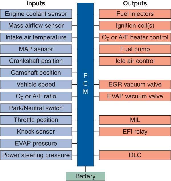
28 23. The PCM receives sensor, processes information, & commands devices. Input, Output Output, Input Milk, Serial
29


30 24. Sensors convert conditions like temperature, speed, pressure, & position to signals. Hydraulic Pneumatic Electrical
 from sensors is")

31 25. Information (serial data) from sensors is shared between modules on the data bus. C.A.N. M.A.N. T.A.N.

32 26. In an ECU, sensor data is stored in the temporary RAM. Permanent data is stored in the. KAM NVRAM ROM

33 27. tables (sometimes called maps) contain specific vehicle calibrations and specifications. Look up Wipe up Pump up

34 28. The PCM makes decisions based on look up tables, sensor inputs, and system. Thoughts Strategy Operation
35 29. To control a system, the PCM determines the of engine operation, then the to be reached, and finally what actions are necessary to achieve the desired goal. Mode, Goal Mode, Purpose Mode, Destination

36 30. Other than basic engine operation, the PCM can also control valve timing, cylinder, electronic control, & variable manifolds. Variable, Deactivation, Throttle, Intake Variable, Activation, Throttle, Exhaust Variable, Deactivation, Compressor, Intake

37 30. Other than basic engine operation, the PCM can also control valve timing, cylinder, electronic control, & variable manifolds. Variable, Deactivation, Throttle, Intake Variable, Activation, Throttle, Exhaust Variable, Deactivation, Compressor, Intake


38 30. Other than basic engine operation, the PCM can also control valve timing, cylinder, electronic control, & variable manifolds. Variable, Deactivation, Throttle, Intake Variable, Activation, Throttle, Exhaust Variable, Deactivation, Compressor, Intake

39 31. Non engine functions that are controlled by the PCM include AC operation, transmission shift solenoids, cruise control, and transmission torque converter clutch engagement. Compressor Evaporator Condenser


40 32. OBD I systems were first used in was required starting with the 1996 model year. OBD Next Gen OBD II OBD III


41 33. OBD II required 20 basic data parameters in the serial data stream and functions which are self tests of such things like catalyst efficiency, engine misfire detection, evaporative system, secondary air, and exhaust gas recirculation flow rate. (continuous & non continuous) Monitor Sequencing Protocol


42 34. OBD II systems must illuminate the MIL if emissions exceed times the allowable standard

43 35. In the OBD II DLC, of the 16 pins have been assigned specific data or tasks. The DLC should always be located within a foot to the right or left of the steering wheel & must be accessible

44 36. Through the SAE J1930 standard, OBD II mandated that common terms & for all engine & emission controls be used for gasoline & light duty diesel vehicles. Acronyms Mnemonics PIDS

45 37. is on its way, including ways to automatically read DTCs off of a vehicle by phone, radio, or satellite without a direct hook up. This reduces time between detection of a problem & repair. OBD III OBD IV OBD V
46 38. Modes of operation in an electronic control system are often called control. Input Process Output Input Process Output Scoops Protocols Loops
47 39. loop is called a feedback system with detection, data digestion, action & re checks. (obedience & rationality) Open Closed Fail Safe

48 40. loop does not use feedback & is therefore a time of slightly more pollution from the vehicle and less performance. Open Closed Fail Safe

49 41. Fail safe or mode is when the PCM takes control of the system if critical input is lost or is well out of range. It allows the engine to run until the driver reaches a service location. Open Closed Limp in

50 42. Adaptive is a plan for the timing and control of computercontrolled systems during different operating conditions. Adaptations usually have short term and long term strategies. Performance Strategy Methods

51 43. OBD II monitors parameters or conditions of operation for detection of failing systems & will actually illuminate the MIL during out of range operation, before a complete system failure. Late Early Modular
52 44. Some monitors run. (Fuel Trim, Misfire, & Comprehensive Component) (also known as OBD II readiness monitors) Intermittently Continuously On Demand
53 45. Non continuous monitors only run when certain or operating conditions have been met. These criteria may be OBD II drive cycles, trips, or warm up cycles. Enable Criteria Event Criteria Enhancing Criteria


54 46. The OBD II drive cycle must occur before can take place & any DTCs can be set. In a complete drive cycle all monitors followed by the catalyst are done. Self Diagnosis Self Monitoring Self Activating


55 47. Unfortunately an OBD II drive cycle is not standard for all manufacturers. True or False
56 48. An OBD II is a drive cycle that meets all enable criteria required for a monitor to run. Run Trip Fall

57 49. An OBD II cycle is the period of time from when the engine is started to when the engine temperature has increased by at least 60 F and has reached at least 160 F. Drive by Warm up Cool off


58 50. Data from upstream & downstream sensors is used for the catalyst efficiency monitor. Hydrogen Nitrogen Oxygen

59 51. Cylinder monitoring is done by measuring the contribution of each cylinder to total engine power. The CKP is used to detect crankshaft deceleration & acceleration for misfire monitoring. Performance Misfire Detonation


60 52. A Type misfire (happens 2% to 20% of the time) is checked for in 200 RPM increments. A B C
61 53. Type A misfires illuminate the MIL & the PCM shuts off to the malfunctioning cylinder. Fuel Air Coolant

62 54. Type misfire is checked over a 1000 RPM period of time. Type B misfires set a pending DTC. A B C
 Both Term (STFT) & Term (LTFT).")
63 55. Fuel is continuously monitored. (CCM) Both Term (STFT) & Term (LTFT). Trim, Short, Long Shave, Short, Long Style, Short, Long

64 56. Lean to Rich & Rich to Lean sensor response time are monitored 1x drive cycle. Crankshaft Camshaft Oxygen
")
65 57. system monitoring varies with vehicle. (flow rate, position, MAP change, pressure feedback) EGR AIR EVAP PCV
66 57. system monitoring varies with vehicle. (flow rate, position, MAP change, pressure feedback) EGR AIR EVAP PCV

67 58. system monitors check for system integrity against leaks and for purge flow. EGR Evaporative Secondary Air
68 59. system operation can be checked by diverting air flow upstream of the HO 2 sensor and then monitoring it s response. (voltage should drop since lean exhaust = low volts) EGR Evaporative Secondary Air


69 60. Since 2002, all vehicles monitor operation and set a pending code if required engine temperature is not reached in a specified period of time. Heater Core Evaporator Thermostat

70 61. The system can be monitored by watching HO 2 S signals for consistent lean readings. EGR AIR EVAP PCV

71 61. The system can be monitored by watching HO 2 S signals for consistent lean readings. EGR AIR EVAP PCV

72 62. The component monitor is a continuous monitor that looks at inputs & outputs that would affect emission levels. Checks for out of range values and rationality checks are done. Evaporative Comprehensive Selective


73 63. Not all problems will activate the MIL or store a DTC. True or False


74 64. According to OBD II regulations, the must illuminate the when a problem that affects emissions is detected. A misfire that is CAT damaging will constantly blink the MIL. PCM, DTC PCM, DLC PCM, MIL
75 65. DTCs only indicate the & the where a fault has been detected. Circuit, System Time, Place RPM, Temperature
76
77 66. There are 1 trip, 2 trip, and DTC s. **All 5 character DTCs begin with a letter. P = B = C = U = Pending Spending Frozen P = Powertrain, Powder Keg, Pontiac B = Body, Basic, Banana Boat C = Cruise, Chassis, Common U = Undefined, UART, Universal Asynchronous Receiver Transmitter

78 67. The snapshot feature in the PCM is officially known as. Freeze Frame You Tube Movie Trailer
 is captured when a DTC is set.")
79 68. A freeze frame of actual values (not adaptive strategy) is captured when a DTC is set. True or False
80 69. Scanners offer a look at 9 test modes: Mode 1 is or serial data mode Mode 2 is data access mode Mode 3 is used to observe stored Mode 4 is PCM mode that allows DTCs to be cleared from the RAM Mode 5 is the sensor monitoring test. It shows stored values during a test cycle Mode 6 is the state mode of the non continuous monitored systems Mode 7 reports the test results for the monitoring systems (Fuel, CCM, Misfire) Mode 8 allows the bi directional control to do functional tests of systems Mode 9 has the, calibration identification, calibration verification for the vehicle
81 69. Scanners offer a look at 9 test modes: Mode 1 is PARAMETER IDENTIFICATION or serial data mode Mode 2 is FREEZE FRAME data access mode Mode 3 is used to observe stored DTC s Mode 4 is PCM RESET mode that allows DTCs to be cleared from the RAM Mode 5 is the OXYGEN sensor monitoring test. It shows stored values during a test cycle Mode 6 is the OUTPUT state mode of the non continuous monitored systems Mode 7 reports the test results for the CONTINUOUS monitoring systems (Fuel, CCM, Misfire) Mode 8 allows the TECHNICIAN bi directional control to do functional tests of systems Mode 9 has the VIN, calibration identification, calibration verification for the vehicle


82 70. Troubleshooting is a approach to diagnosis along with the use TSBs & repair data. Diagnostic Guesswork Uninformed
83 71. faults are hard to diagnose, but are most often caused by faulty connections. Frozen Continuous Intermittent


84 72. By the push of a key, scan tools can do a snapshot while on a drive as a problem occurs. Test Rest Pest

85 73. In Mode 6: TIDs are IDs and CIDs are IDs and are hexadecimal values. Test, Content Tuning, Content Test, Component


86 74. had limited data, no freeze frame, & could blink the MIL to give DTCs in self test mode. OBD I
Auto Diagnosis Test #7 Review
 Auto Diagnosis Test #7 Review Your own hand written notes may be used for the 1 st 10 minutes of the test Based on Chapters 25, 26, 32, 33, 34 and Lab Demonstrations Auto Diagnosis Test #7 Review Your
For. Code Reader. User Manual
 For OBD2 Code Reader User Manual http://www.motodok.com Table of Contents 1. Description... 2 2. Features... 2 3. Getting Started... 3 1. Connect Code Reader to Vehicle's Test Connector... 3 2. Read Diagnostic
ATASA 5 th. Detailed Diagnosis & Sensors. Please Read The Summary
 ATASA 5 TH Study Guide Chapter 26 Pages 764 809 51 Points Please Read The Summary 1. Many different sensors are involved in the overall driveability of a vehicle. Input Processing Output Electronic Engine
Chapter 20 OBD-II Diesel Monitors
 Light Vehicle Diesel Engines First Edition Chapter 20 OBD-II Diesel Monitors LEARNING OBJECTIVES (1 of 2) 20.1 Prepare for the Light Vehicle Diesel Engine (A9) ASE certification fuel system diagnosis and
Powertrain DTC Summaries EOBD
 Powertrain DTC Summaries Quick Reference Diagnostic Guide Jaguar X-TYPE 2.0 L 2002.25 Model Year Refer to page 2 for important information regarding the use of Powertrain DTC Summaries. Jaguar X-TYPE 2.0
On Board Diagnostics (OBD) Monitors
 Monitors") 2007 PCED On Board Diagnostics SECTION 1: Description and Operation Procedure revision date: 03/29/2006 On Board Diagnostics (OBD) Monitors OBD-I, OBD-II and Engine Manufacturer Diagnostics (EMD) Overview
2007 PCED On Board Diagnostics SECTION 1: Description and Operation Procedure revision date: 03/29/2006 On Board Diagnostics (OBD) Monitors OBD-I, OBD-II and Engine Manufacturer Diagnostics (EMD) Overview
Powertrain DTC Summaries EOBD
 Powertrain DTC Summaries Quick Reference Diagnostic Guide Jaguar S-TYPE V6, V8 N/A and V8 SC 2002.5 Model Year Refer to pages 2 9 for important information regarding the use of Powertrain DTC Summaries.
(P0135/P0155), (P0141/P0161), (P1131/P1151), (P1132/P1152). To further clarify this, see the more detailed scenario as follows:
, (P0141/P0161), (P1131/P1151), (P1132/P1152). To further clarify this, see the more detailed scenario as follows:") 1. Always reset KAM after performing a repair: After performing a repair on a vehicle with the MIL on, and/or DTCs present, always clear KAM. When a malfunction is present, the PCM adapts (attempts to
1. Always reset KAM after performing a repair: After performing a repair on a vehicle with the MIL on, and/or DTCs present, always clear KAM. When a malfunction is present, the PCM adapts (attempts to
Diagnostic Trouble Code (DTC) List - Vehicle
 List - Vehicle") Document ID# 850406 2002 Pontiac Firebird Diagnostic Trouble Code (DTC) List - Vehicle DTC DTC 021 and/or 031 DTC 022 and/or 032 DTC 023 or 033 DTC 24/34 DTC 025 and/or 035 DTC 041 DTC 042 DTC 043 DTC
Document ID# 850406 2002 Pontiac Firebird Diagnostic Trouble Code (DTC) List - Vehicle DTC DTC 021 and/or 031 DTC 022 and/or 032 DTC 023 or 033 DTC 24/34 DTC 025 and/or 035 DTC 041 DTC 042 DTC 043 DTC
YOU CAN DO IT!... 1 SAFETY PRECAUTIONS SAFETY FIRST!... 2
 Table of Contents YOU CAN DO IT!... 1 SAFETY PRECAUTIONS SAFETY FIRST!... 2 ABOUT THE CODE READER VEHICLES COVERED... 3 CONTROLS AND INDICATORS... 4 DISPLAY FUNCTIONS... 5 ONBOARD DIAGNOSTICS COMPUTER
Table of Contents 1. INTRODUCTION GENERAL INFORMATION-ABOUT OBDII/EOBD PRODUCT DESCRIPTIONS OPERATIONS...11
 Table of Contents 1. INTRODUCTION...1 2. GENERAL INFORMATION-ABOUT OBDII/EOBD...1 2.1 ON-BOARD DIAGNOSTICS (OBD) II...1 2.2 DIAGNOSTIC TROUBLE CODES (DTCS)...2 2.3 LOCATION OF THE DATA LINK CONNECTOR (DLC)...3
 Verified Fix #1 Tool Data Diagnostic Trouble Code Information Report Customer #1 VIN: JT8BL69SX4G015327 Customer Name: Year: 2004 Customer Phone#: 123-123-1234 Make: Lexus Report#: 162 Model: GS 430 Date
YOU CAN DO IT!... 1 SAFETY PRECAUTIONS SAFETY FIRST!... 2
 Table of Contents YOU CAN DO IT!... 1 SAFETY PRECAUTIONS SAFETY FIRST!... 2 ABOUT THE VEHICLES COVERED... 3 ADJUSTMENTS AND SETTINGS... 4 CONTROLS AND INDICATORS... 6 DISPLAY FUNCTIONS... 7 ONBOARD DIAGNOSTICS
Powertrain DTC Summaries OBD II
 Powertrain DTC Summaries Quick Reference Diagnostic Guide Jaguar X-TYPE 2.5L and 3.0L 2002 Model Year Revised January, 2002: P0706, P0731, P0732, P0733, P0734, P0735, P0740, P1780 POSSIBLE CAUSES Revised
Emissions Theory and Diagnostics
 SECTION 1 Introduction 5-Gas Theory Emissions History OBD II SECTION 2 PCV System Function Failure Diagnosis Emissions Theory and Diagnostics SECTION 3 EGR EGR Theory Vacuum Systems Backpressure Systems
Powertrain DTC Summaries EOBD
 Powertrain DTC Summaries Quick Reference Diagnostic Guide Jaguar X-TYPE 2.5L and 3.0L 2001.5 Model Year Revised January, 2002: P0706, P0731, P0732, P0733, P0734, P0735, P0740, P1780 POSSIBLE CAUSES Revised
INDEX. 1.Safety Precautions and Warnings...3
 INDEX 1.Safety Precautions and Warnings...3 2. General Information...5 2.1 On-Board Diagnostics (OBD) II... 5 2.2 Diagnostic Trouble Codes (DTCs)... 6 2.3 Location of the Data Link Connector (DLC)...7
YOU CAN DO IT!... 1 SAFETY PRECAUTIONS SAFETY FIRST!... 2
 Table of Contents YOU CAN DO IT!... 1 SAFETY PRECAUTIONS SAFETY FIRST!... 2 ABOUT THE SCAN TOOL VEHICLES COVERED... 3 CONTROLS AND INDICATORS... 4 DISPLAY FUNCTIONS... 5 DISPLAY AND SETTINGS... 6 ONBOARD
OBDII INSPECTION GUIDE
 OBDII INSPECTION GUIDE Texas Department of Public Safety September 2002 Prepared by: dkc de la Torre Klausmeier Consulting, Inc. ª2002 dkc Table of Contents GLOSSARY OF OBD TERMS...2 INTRODUCTION...12
INTRODUCTION WHAT IS OBD?... 1 YOU CAN DO IT!... 2 SAFETY PRECAUTIONS SAFETY FIRST!... 3
 Table of Contents INTRODUCTION WHAT IS OBD?... 1 YOU CAN DO IT!... 2 SAFETY PRECAUTIONS SAFETY FIRST!... 3 ABOUT THE CODE READER VEHICLES COVERED... 4 CONTROLS AND INDICATORS... 5 DISPLAY FUNCTIONS...
2UZ-FE ENGINE CONTROL SYSTEM SFI SYSTEM
 160 2UZ-FE EINE CONTROL SYSTEM SFI SYSTEM DTC P0171 System Too Lean (Bank 1) DTC P0172 System Too Rich (Bank 1) DTC P0174 System Too Lean (Bank 2) DTC P0175 System Too Rich (Bank 2) DCRIPTION The fuel
DTC P0420 or P0430. Circuit Description. DTC Descriptors. Conditions for Running the DTC
 Page 1 of 5 2005 Cadillac STS STS (VIN D) Service Manual Engine Engine Controls - 4.6L (LH2) Diagnostic Information and Procedures DTC P0420 or P0430 Circuit Description A three-way catalytic converter
OBD II Data Interpretation
 OBD II Data Interpretation What is OBDII? OBDII stands for on board diagnostics second generation superseding that of OBD1.OBDII is a system that was mandated by the Federal EPA and was developed by the
ABOUT THE DIAGNOSTIC TOOL
 Table of Contents INTRODUCTION WHAT IS OBD?... 1 YOU CAN DO IT!... 2 SAFETY PRECAUTIONS SAFETY FIRST!... 3 ABOUT THE DIAGNOSTIC TOOL VEHICLES COVERED... 5 BATTERY REPLACEMENT... 6 DIAGNOSTIC TOOL CONTROLS
ENGINE 01 02A 1. Toc of SCT ON-BOARD DIAGNOSTIC [ENGINE. Toc of SCT 01 02A ON-BOARD DIAGNOSTIC [ENGINE CONTROL SYSTEM (ZM)] 01 02A
![ENGINE 01 02A 1. Toc of SCT ON-BOARD DIAGNOSTIC [ENGINE. Toc of SCT 01 02A ON-BOARD DIAGNOSTIC [ENGINE CONTROL SYSTEM (ZM)] 01 02A](/thumbs/90/103285807.jpg "ENGINE 01 02A 1. Toc of SCT ON-BOARD DIAGNOSTIC [ENGINE. Toc of SCT 01 02A ON-BOARD DIAGNOSTIC [ENGINE CONTROL SYSTEM (ZM)] 01 02A") ENGINE 01 SECTION Toc of SCT ON-BOARD DIAGNOSTIC [ENGINE CONTROL SYSTEM (ZM)]...01-02A ON-BOARD DIAGNOSTIC [ENGINE CONTROL SYSTEM (FS)]...01-02B ON-BOARD DIAGNOSTIC [CRUISE CONTROL SYSTEM].......01-02C
ENGINE 01 SECTION Toc of SCT ON-BOARD DIAGNOSTIC [ENGINE CONTROL SYSTEM (ZM)]...01-02A ON-BOARD DIAGNOSTIC [ENGINE CONTROL SYSTEM (FS)]...01-02B ON-BOARD DIAGNOSTIC [CRUISE CONTROL SYSTEM].......01-02C
01 02B ON-BOARD DIAGNOSTIC [ENGINE CONTROL SYSTEM (FS)]
![01 02B ON-BOARD DIAGNOSTIC [ENGINE CONTROL SYSTEM (FS)]](/thumbs/80/80600627.jpg "01 02B ON-BOARD DIAGNOSTIC [ENGINE CONTROL SYSTEM (FS)]") ON-BOARD DIAGNOSTIC [ENGINE CONTROL SYSTEM (FS)] CONTROL SYSTEM WIRING DIAGRAM [FS]............................ 2 CONTROL SYSTEM DEVICE AND CONTROL RELATIONSHIP CHART [FS]........ 4 Engine Control System............
ON-BOARD DIAGNOSTIC [ENGINE CONTROL SYSTEM (FS)] CONTROL SYSTEM WIRING DIAGRAM [FS]............................ 2 CONTROL SYSTEM DEVICE AND CONTROL RELATIONSHIP CHART [FS]........ 4 Engine Control System............
DTC P0171 SYSTEM TOO LEAN (BANK 1) DTC P0174 SYSTEM TOO LEAN (BANK 2)
 DTC P0174 SYSTEM TOO LEAN (BANK 2)") 05498 DIAGNOSTICS DTC P0171 SYSTEM TOO LEAN (BANK 1) 05EXR06 DTC P0172 SYSTEM TOO RICH (BANK 1) DTC P0174 SYSTEM TOO LEAN (BANK 2) DTC P0175 SYSTEM TOO RICH (BANK 2) CIRCUIT DESCRIPTION The fuel trim is
05498 DIAGNOSTICS DTC P0171 SYSTEM TOO LEAN (BANK 1) 05EXR06 DTC P0172 SYSTEM TOO RICH (BANK 1) DTC P0174 SYSTEM TOO LEAN (BANK 2) DTC P0175 SYSTEM TOO RICH (BANK 2) CIRCUIT DESCRIPTION The fuel trim is
DTC P0171, P0172, P0174, or P0175
 Page 1 of 6 2009 Pontiac G8 G8 Service Manual Document ID: 2076050 DTC P0171, P0172, P0174, or P0175 Diagnostic Instructions Perform the Diagnostic System Check - Vehicle prior to using this diagnostic
2002 ENGINE PERFORMANCE. Self-Diagnostics - RAV4. Before performing testing procedures, check for any related Technical Service Bulletins (TSBs).
.") 2002 ENGINE PERFORMANCE Self-Diagnostics - RAV4 INTRODUCTION NOTE: Before performing testing procedures, check for any related Technical Service Bulletins (TSBs). To properly diagnosis and repair this
2002 ENGINE PERFORMANCE Self-Diagnostics - RAV4 INTRODUCTION NOTE: Before performing testing procedures, check for any related Technical Service Bulletins (TSBs). To properly diagnosis and repair this
INTRODUCTION. FOR ios DEVICES
 Table of Contents INTRODUCTION ABOUT QUICKLINK... 1 Vehicles Covered... 1 The QUICKLINK Device... 2 The QUICKLINK App... 2 COMPUTER ENGINE CONTROLS... 2 The Introduction of Electronic Engine Controls...
DTC P0420. Circuit Description. Conditions for Running the DTC.
 Page 1 of 5 DTC P0420 2003 Buick LeSabre LeSabre (VIN H) Service Manual Document ID: 792202 Circuit Description In order to control emissions of hydrocarbons (HC), carbon monoxide (CO), and oxides of nitrogen
Diagnostic Report. Monitor Status Report. Page 1 of 12. Date: 12/18/2016 9:17:03 PM
 file:///c:/users/rbirkenholz/app/local/microsoft/windows/temporary%20internet... Page 1 of 12 Diagnostic Report Created by OBDLink - OBD Solutions www.obdsoftware.net Date: 12/18/2016 9:17:03 PM VIN: 1D8HB58287F580896
DTC Summaries. NipponDenso V12 Engine Management
 DTC Summaries NipponDenso V12 Engine Management OBD II MONITORING CONDITIONS: When testing for DTC reoccurrence, it can be determined if the Service Drive Cycle was of sufficient length by performing a
DIAGNOSTIC TROUBLE CODE CHART HINT:
 DIAGNOSTICS DIAGNOSTIC TROUBLE CODE CHART HINT: SFI SYSTEM (1MZFE) 05241 Parameters listed in the chart may not be exactly the same as your reading due to the type of instrument or other factors. If a
DTC P0172 Fuel Trim System Rich
 Page 1 of 6 1997 Chevrolet Cavalier Cavalier, Sunfire (VIN J) Service Manual Document ID: 47788 DTC P0172 Fuel Trim System Rich System Description A Closed Loop air/fuel metering system is used to provide
Engine Systems. Basic Engine Operation. Firing Order. Four Stroke Cycle. Overhead Valves - OHV. Engine Design. AUMT Engine Systems 4/4/11
 Advanced Introduction Brake to Automotive Systems Diagnosis Service and Service Basic Engine Operation Engine Systems Donald Jones Brookhaven College The internal combustion process consists of: admitting
INTRODUCTION WHAT IS OBD?... 1 YOU CAN DO IT!... 2
 Table of Contents INTRODUCTION WHAT IS OBD?... 1 YOU CAN DO IT!... 2 ABOUT THE SCAN TOOL SAFETY FIRST!... 3 VEHICLES COVERED... 4 CONTROLS AND INDICATORS... 5 DISPLAY FUNCTIONS... 6 INITIAL ADJUSTMENTS...
GROUP 13Ab. 13Ab-2 CONTENTS TROUBLESHOOTING STRATEGY.. DATA LIST REFERENCE TABLE... 13Ab-29 TROUBLE CODE DIAGNOSIS...
 13Ab-1 GROUP 13Ab CONTENTS TROUBLESHOOTING STRATEGY.. 13Ab-2 DATA LIST REFERENCE TABLE... 13Ab-29 TROUBLE CODE DIAGNOSIS..... 13Ab-2 FAIL-SAFE FUNCTION REFERENCE TABLE........................ 13Ab-20 DIAGNOSTIC
1. OBD II Readiness Monitors An important part of a vehicle s OBD II system is the Readiness Monitors, which are indicators used to find out if all
 1. OBD II Readiness Monitors An important part of a vehicle s OBD II system is the Readiness Monitors, which are indicators used to find out if all of the emissions components have been evaluated by the
DTC P1415 Secondary Air Injection (AIR) System Bank 1
 System Bank 1") Page 1 of 5 2000 GMC Truck GMC K Sierra - 4WD Sierra, Silverado, Suburban, Tahoe, Yukon (VIN C/K) Service Manual Document ID: 546887 DTC P1415 Secondary Air Injection (AIR) System Bank 1 Circuit Description
Page 1 of 5 2000 GMC Truck GMC K Sierra - 4WD Sierra, Silverado, Suburban, Tahoe, Yukon (VIN C/K) Service Manual Document ID: 546887 DTC P1415 Secondary Air Injection (AIR) System Bank 1 Circuit Description
OWNER S MANUAL. The Easiest And Best Way To Troubleshoot 1996 and Newer OBD II Vehicles!
 OWNER S MANUAL The Easiest And Best Way To Troubleshoot 1996 and Newer OBD II Vehicles! E1 Table of Contents Paragraph Title Page No. YOU CAN DO IT!.............................. ii GENERAL INFORMATION
Five-digit error code First position: P - is for powertrain codes B - is for body codes C - is for chassis codes
 https://www.automotive-manuals.net Five-digit error code First position: P - is for powertrain codes B - is for body codes C - is for chassis codes The second position: 0 - the total for the OBD-II code
Fuel Metering System Component Description
 1999 Chevrolet/Geo Tahoe - 4WD Fuel Metering System Component Description Purpose The function of the fuel metering system is to deliver the correct amount of fuel to the engine under all operating conditions.
ARTICLE BEGINNING INTRODUCTION SELF-DIAGNOSTIC SYSTEM RETRIEVING DTCS ENGINE PERFORMANCE Volkswagen Self-Diagnostics - Gasoline
 Article Text ARTICLE BEGINNING 1996 ENGINE PERFORMANCE Volkswagen Self-Diagnostics - Gasoline Cabrio, Golf III, GTI, Jetta III, Passat INTRODUCTION If no faults were found while performing preliminary
DTC P0174 Fuel Trim System Lean Bank 2
 2000 Chevrolet/Geo S10 Pickup - 4WD DTC P0174 Fuel Trim System Lean Bank 2 Circuit Description In order to provide the best possible combination of driveability, fuel economy, and emission control, the
DTC P0134 OXYGEN SENSOR CIRCUIT NO ACTIVITY DETECTED (BANK 1 SENSOR 1)
") 05114 DIAGNOSTICS 05CRQ04 DTC P0134 OXYGEN SENSOR CIRCUIT NO ACTIVITY DETECTED (BANK 1 SENSOR 1) CIRCUIT DESCRIPTION Refer to DTC P0130 on page 0596. DTC No. DTC Detecting Condition Trouble Area After
05114 DIAGNOSTICS 05CRQ04 DTC P0134 OXYGEN SENSOR CIRCUIT NO ACTIVITY DETECTED (BANK 1 SENSOR 1) CIRCUIT DESCRIPTION Refer to DTC P0130 on page 0596. DTC No. DTC Detecting Condition Trouble Area After
Lotus Service Notes Section EMD
 ENGINE MANAGEMENT SECTION EMD Lotus Techcentre Sub-Section Page Diagnostic Trouble Code List EMD.1 3 Component Function EMD.2 8 Component Location EMD.3 10 Diagnostic Guide EMD.4 11 CAN Bus Diagnostics;
OBD-II Diagnostic Powertrain (P) Trouble Codes
 Trouble Codes") OBD-II Diagnostic Powertrain (P) Trouble Codes Please use our new & improved search engine to find information on your trouble codes. Search Now! This list contains standard diagnostic trouble codes (DTC
OBD-II Diagnostic Powertrain (P) Trouble Codes Please use our new & improved search engine to find information on your trouble codes. Search Now! This list contains standard diagnostic trouble codes (DTC
Fuel Supply & ME-SFI Engine Management Emission Systems (Part 12) 508 HO Part 12 - Emission systems (WJB)
 508 HO Part 12 - Emission systems (WJB)") Fuel Supply & ME-SFI Engine Management Emission Systems (Part 12) 508 HO Part 12 - Emission systems (WJB) 04-01-01 1 These technical training materials are current as of the date noted on the materials,
Fuel Supply & ME-SFI Engine Management Emission Systems (Part 12) 508 HO Part 12 - Emission systems (WJB) 04-01-01 1 These technical training materials are current as of the date noted on the materials,
Lambda Control Fuel Adaptation and Fuel Trim
 Lambda Control Fuel Adaptation and Fuel Trim Q: What is Lambda and Lambda Control? A: In the case of a gasoline engine, the optimal mixture of air to fuel for complete combustion is a ratio of 14.7 parts
Powertrain Control Software
 2007 PCED On Board Diagnostics SECTION 1: Description and Operation Procedure revision date: 03/29/2006 Powertrain Control Software Computer Controlled Shutdown The powertrain control module (PCM) controls
DTC P0420 CATALYST SYSTEM EFFICIENCY BELOW THRESHOLD (BANK 1) DTC P0430 CATALYST SYSTEM EFFICIENCY BELOW THRESHOLD (BANK 2)
 DTC P0430 CATALYST SYSTEM EFFICIENCY BELOW THRESHOLD (BANK 2)") DIAGNOSTICS DTC P0420 CATALYST SYSTEM EFFICIENCY BELOW THRESHOLD (BANK 1) 05551 05BNU11 DTC P0430 CATALYST SYSTEM EFFICIENCY BELOW THRESHOLD (BANK 2) MONITOR DESCRIPTION The ECM uses sensors mounted before
DIAGNOSTICS DTC P0420 CATALYST SYSTEM EFFICIENCY BELOW THRESHOLD (BANK 1) 05551 05BNU11 DTC P0430 CATALYST SYSTEM EFFICIENCY BELOW THRESHOLD (BANK 2) MONITOR DESCRIPTION The ECM uses sensors mounted before
DTC P0134 OXYGEN SENSOR CIRCUIT NO ACTIVITY DETECTED (BANK 1 SENSOR 1)
") 05 120 05CRQ 02 DTC P0134 OXYGEN SENSOR CIRCUIT NO ACTIVITY DETECTED (BANK 1 SENSOR 1) CIRCUIT DESCRIPTION Refer to DTC P0130 on page 05 101. DTC No. DTC Detecting Condition Trouble Area P0134 After engine
05 120 05CRQ 02 DTC P0134 OXYGEN SENSOR CIRCUIT NO ACTIVITY DETECTED (BANK 1 SENSOR 1) CIRCUIT DESCRIPTION Refer to DTC P0130 on page 05 101. DTC No. DTC Detecting Condition Trouble Area P0134 After engine
Table of Contents. CarScan+OBD1
 Table of Contents INTRODUCTION WHAT IS OBD?... 1 YOU CAN DO IT!... 2 SAFETY PRECAUTIONS SAFETY FIRST!... 3 ABOUT THE SCAN TOOL VEHICLES COVERED... 5 BATTERY REPLACEMENT... 6 SCAN TOOL CONTROLS CONTROLS
Table of Contents. 3120f
 Table of Contents INTRODUCTION WHAT IS OBD?... 1 YOU CAN DO IT!... 2 SAFETY PRECAUTIONS SAFETY FIRST!... 3 ABOUT THE DIAGNOSTIC TOOL VEHICLES COVERED... 5 BATTERY REPLACEMENT... 6 DIAGNOSTIC TOOL CONTROLS
PREPARATION FOR TESTING
 Table of Contents INTRODUCTION WHAT IS OBD?... 1 YOU CAN DO IT!... 2 SAFETY PRECAUTIONS SAFETY FIRST!... 3 ABOUT THE FIXADVISOR VEHICLES COVERED... 5 BATTERY REPLACEMENT... 6 ADJUSTMENTS AND SETTINGS...
Diagnostic Trouble Codes (continued) SAE Defined Codes
 SAE Defined Codes") 78 SAE Defined Codes P01XX Fuel and Air Metering P0100 Mass or Volume Airflow Circuit Problem P0101 Mass or Volume Airflow Circuit Range or Performance Problem P0102 Mass or Volume Airflow Circuit Low
78 SAE Defined Codes P01XX Fuel and Air Metering P0100 Mass or Volume Airflow Circuit Problem P0101 Mass or Volume Airflow Circuit Range or Performance Problem P0102 Mass or Volume Airflow Circuit Low
P2098-DOWNSTREAM FUEL TRIM SYSTEM 2 LEAN
 - DS - RAM 500 PICKUP -.6L V6 V.V.T. P98-DOWNSTREAM FUEL TRIM SYSTEM LEAN BATTERY A0 0 87 87A RELAY- RUN/ START ASSEMBLY- POWER DISTRIBUTION CENTER FUSE A FUSE 78 0A CONNECTOR- STAR CAN C DASH 8 C CAN
1GR-FE ENGINE CONTROL SYSTEM SFI SYSTEM
 134 1GR-FE EINE CONTROL SYSTEM SFI SYSTEM DTC P0136 Oxygen Sensor Circuit Malfunction (ank 1 Sensor ) DTC P0137 Oxygen Sensor Circuit Low Voltage (ank 1 Sensor ) DTC P0138 Oxygen Sensor Circuit High Voltage
Learning Guide EMISSION SPECIALIST 5 GAS ANALYSIS COURSE NUMBER: E001-01
 Learning Guide EMISSION SPECIALIST 5 GAS ANALYSIS COURSE NUMBER: E001-01 Notice Due to the wide range of vehicles makes and models, the information given during the class will be general in nature and
Alternative Fuel Engine Control Unit
 1999 Chevrolet/Geo Cavalier (CNG) Alternative Fuel Engine Control Unit Table 1: AF ECU Function Parameters The (AF ECU) controls alternative fuel engine operation. The control unit monitors various engine
Lotus Service Notes Section EMR
 ENGINE MANAGEMENT SECTION EMR Lotus Techcentre Sub-Section Page Diagnostic Trouble Code List EMR.1 3 Component Function EMR.2 7 Component Location EMR.3 9 Diagnostic Guide EMR.4 11 CAN Bus Diagnostics;
The engine is running. DTC P0351, P0352, P0353, and P0354 run continuously once the above condition has been met.
 Page 1 of 6 DTC P0351-P0354 Circuit Description DTCs P0351 through P0354 Ignition Coil Primary/Secondary Feedback Circuit diagnostic monitors the primary circuitry of individual ignition coils for the
E - THEORY/OPERATION - TURBO
 E - THEORY/OPERATION - TURBO 1995 Volvo 850 1995 ENGINE PERFORMANCE Volvo - Theory & Operation 850 - Turbo INTRODUCTION This article covers basic description and operation of engine performance-related
OBD2 ECU Simulator. User Manual IMSB5010.
 OBD2 ECU Simulator User Manual http://www.imsapp.com Modes MODE 01:Show current data MODE 02:Show freeze frame data MODE 03:Show stored Diagnostic Trouble Codes MODE 04:Clear Diagnostic Trouble Codes and
Service Bulletin. DTC Detection Item Associated Monitor
 Service Bulletin 03-010 Applies To: All OBD II equipped models except SLX March 29, 2003 OBD II DTCs and Their Associated Monitors This is a list of all DTCs for all OBD II models. No one model has all
INTRODUCTION WHAT IS OBD?... 1 YOU CAN DO IT!... 2 SAFETY PRECAUTIONS SAFETY FIRST!... 3
 Table of Contents INTRODUCTION WHAT IS OBD?... 1 YOU CAN DO IT!... 2 SAFETY PRECAUTIONS SAFETY FIRST!... 3 ABOUT THE CODE READER VEHICLES COVERED... 5 BATTERY REPLACEMENT... 6 ADJUSTMENTS/SETTINGS AND
Adaptive Fuel DTC Diagnostic Techniques
 2007 PCED On Board Diagnostics SECTION 2: Diagnostic Methods Procedure revision date: 03/29/2006 Adaptive Fuel DTC Diagnostic Techniques The Adaptive Fuel Diagnostic Trouble Codes (DTC) Diagnostic Techniques
User s Manual XOB15091 OBD II / EOBD CODE READER. All Rights Reserved. Warranty and Service
 5. Warranty and Service 5.1 Limited One Year Warranty The manufacturer/supplier warranty provided to customers for this product will be free from all defects in materials and workmanship for a period of
2002 Buick Rendezvous - AWD
 2002 Buick Rendezvous - AWD DTC P0410 Description The control module activates the secondary air injection (AIR) system by grounding both the pump relay and the vacuum control solenoid control circuits.
UNDERSTANDING 5 GAS DIAGNOSIS
 UNDERSTANDING 5 GAS DIAGNOSIS AND EMISSIONS Gas Diagnostic Steps This procedure will help in your efforts to figure out what the five-gas reading are telling you. In order for five gas analyses to be conclusive
DTC P0420 CATALYST SYSTEM EFFICIENCY BELOW THRESHOLD (BANK 1)
") DTC P0420 CATALYST SYSTEM EFFICIENCY BELOW THRESHOLD (BANK 1) 05195 05FNS02 MONITOR DESCRIPTION The ECM uses 2 sensors mounted before and after the threeway catalytic converter (TWC) to monitor its efficiency.
DTC P0420 CATALYST SYSTEM EFFICIENCY BELOW THRESHOLD (BANK 1) 05195 05FNS02 MONITOR DESCRIPTION The ECM uses 2 sensors mounted before and after the threeway catalytic converter (TWC) to monitor its efficiency.
DTC P1655 Evaporative Emission (EVAP) Purge Solenoid Control Circuit
 Purge Solenoid Control Circuit") Page 1 of 5 1997 Pontiac Grand Am Achieva, Grand Am, Skylark (VIN N) Service Manual Document ID: 58460 DTC P55 Evaporative Emission (EVAP) Purge Solenoid Control Circuit Circuit Description Output Driver
Page 1 of 5 1997 Pontiac Grand Am Achieva, Grand Am, Skylark (VIN N) Service Manual Document ID: 58460 DTC P55 Evaporative Emission (EVAP) Purge Solenoid Control Circuit Circuit Description Output Driver
EMISSION CONTROL (AUX. EMISSION CONTROL DEVICES) H6DO
 H6DO") EMISSION CONTROL (AUX. EMISSION CONTROL DEVICES) H6DO SYSTEM OVERVIEW 1. System Overview There are three emission control systems, which are as follows: Crankcase emission control system Exhaust emission
EMISSION CONTROL (AUX. EMISSION CONTROL DEVICES) H6DO SYSTEM OVERVIEW 1. System Overview There are three emission control systems, which are as follows: Crankcase emission control system Exhaust emission
EMISSION CONTROL (AUX. EMISSION CONTROL DEVICES) H4SO
 H4SO") EMISSION CONTROL (AUX. EMISSION CONTROL DEVICES) H4SO SYSTEM OVERVIEW 1. System Overview There are three emission control systems, which are as follows: Crankcase emission control system Exhaust emission
EMISSION CONTROL (AUX. EMISSION CONTROL DEVICES) H4SO SYSTEM OVERVIEW 1. System Overview There are three emission control systems, which are as follows: Crankcase emission control system Exhaust emission
DTC P0102 Mass Air Flow (MAF) Sensor Circuit Low Frequency
 Sensor Circuit Low Frequency") Page 1 of 5 1997 Pontiac Grand Prix Grand Prix (VIN W) Service Manual Engine Engine Controls - 3.8L Diagnostic Information and Procedures Document ID: 106986 DTC P0102 Mass Air Flow (MAF) Sensor Circuit
Page 1 of 5 1997 Pontiac Grand Prix Grand Prix (VIN W) Service Manual Engine Engine Controls - 3.8L Diagnostic Information and Procedures Document ID: 106986 DTC P0102 Mass Air Flow (MAF) Sensor Circuit
05/14/01 14 mai 2001 Emissions/Engine Controls - Driveability Diagnosis Index - Information - A. Description of Terms and Acronyms - B.
 Article No. 01-9-7 05/14/01 14 mai 2001 Emissions/Engine Controls - Driveability Diagnosis Index - Information - A. Description of Terms and Acronyms - B. HO2S Location Diagrams - C. Heated Oxygen Sensor
E - THEORY/OPERATION ENGINE PERFORMANCE General Motors Corp. - Theory & Operation - 5.7L
 E - THEORY/OPERATION 1998 ENGINE PERFORMANCE General Motors Corp. - Theory & Operation - 5.7L INTRODUCTION This article covers basic description and operation of engine performance-related systems and
EMISSION CONTROL (AUX. EMISSION CONTROL DEVICES) H4DOTC
 H4DOTC") EMISSION CONTROL (AUX. EMISSION CONTROL DEVICES) H4DOTC SYSTEM OVERVIEW 1. System Overview There are three emission control systems, which are as follows: Crankcase emission control system Exhaust emission
EMISSION CONTROL (AUX. EMISSION CONTROL DEVICES) H4DOTC SYSTEM OVERVIEW 1. System Overview There are three emission control systems, which are as follows: Crankcase emission control system Exhaust emission
Model Year: 2007 Model: Tacoma Doc ID: RM H800NX
 Page 1 of 12 Last Modified: 5-7-2008 5.1 C From: 200608 Model Year: 2007 Model: Tacoma Doc ID: RM0000013H800NX Title: 2TR-FE ENGINE CONTROL SYSTEM: SFI SYSTEM: P2A00: A/F Sensor Circuit Slow Response (Bank
EMISSION CONTROL VISUAL INSPECTION PROCEDURES
 EMISSION CONTROL VISUAL INSPECTION PROCEDURES 1992 Infiniti G20 1983-98 GENERAL INFORMATION Emission Control Visual Inspection Procedures All Models * PLEASE READ THIS FIRST * This article is provided
EGR System EGR System Eg 1
 ... Eg 1 Eg-1 EGR Flow Insufficient MONITOR DESCRIPTION If the ECM does not sense the opening of the EGR valve during the diagnostic test, it will conclude that there is a fault in either the EGR valve
ATASA 5 th. ATASA 5 TH Study Guide Chapter 31 Pages EFI Diagnosis & Service 47 Points. Please Read The Summary
 ATASA 5 TH Study Guide Chapter 31 Pages 922 948 47 Points Please Read The Summary 1. Troubleshooting EFI systems requires step by step test procedures mostly due to the many interrelated components and
DTC P0171 SYSTEM TOO LEAN (BANK 1) DTC P0172 SYSTEM TOO RICH (BANK 1) DTC P0174 SYSTEM TOO LEAN (BANK 2) DTC P0175 SYSTEM TOO RICH (BANK 2)
 DTC P0172 SYSTEM TOO RICH (BANK 1) DTC P0174 SYSTEM TOO LEAN (BANK 2) DTC P0175 SYSTEM TOO RICH (BANK 2)") 05155 05NZ501 DTC P0171 SYSTEM TOO LEAN (BANK 1) DTC P0172 SYSTEM TOO RICH (BANK 1) DTC P0174 SYSTEM TOO LEAN (BANK 2) DTC P0175 SYSTEM TOO RICH (BANK 2) CIRCUIT DESCRIPTION These DTCs indicate that the
05155 05NZ501 DTC P0171 SYSTEM TOO LEAN (BANK 1) DTC P0172 SYSTEM TOO RICH (BANK 1) DTC P0174 SYSTEM TOO LEAN (BANK 2) DTC P0175 SYSTEM TOO RICH (BANK 2) CIRCUIT DESCRIPTION These DTCs indicate that the
DTC P0102 Mass Air Flow (MAF) Sensor Circuit Low Frequency
 Sensor Circuit Low Frequency") Seite 1 von 5 Document ID# 187823 1998 Chevrolet/Geo Tahoe - 2WD Print DTC P0102 Mass Air Flow (MAF) Sensor Circuit Low Frequency Circuit Description The mass air flow (MAF) sensor is
Seite 1 von 5 Document ID# 187823 1998 Chevrolet/Geo Tahoe - 2WD Print DTC P0102 Mass Air Flow (MAF) Sensor Circuit Low Frequency Circuit Description The mass air flow (MAF) sensor is
Description P1083 Fuel Control Mixture Lean (Bank 1 Sensor 1) P1084 Fuel Control Mixture Rich (Bank 1 Sensor 1) P1085 Fuel Control Mixture Lean (Bank
 P1084 Fuel Control Mixture Rich (Bank 1 Sensor 1) P1085 Fuel Control Mixture Lean (Bank") Code Description P1083 Fuel Control Mixture Lean (Bank 1 Sensor 1) P1084 Fuel Control Mixture Rich (Bank 1 Sensor 1) P1085 Fuel Control Mixture Lean (Bank 2 Sensor 1) P1086 Fuel Control Mixture Rich (Bank
Code Description P1083 Fuel Control Mixture Lean (Bank 1 Sensor 1) P1084 Fuel Control Mixture Rich (Bank 1 Sensor 1) P1085 Fuel Control Mixture Lean (Bank 2 Sensor 1) P1086 Fuel Control Mixture Rich (Bank
P0401-EGR SYSTEM PERFORMANCE
 P0401-EGR SYSTEM PERFORMANCE P0401-EGR SYSTEM PERFORMANCE http://dh.identifix.com/searchfixes/index?roid=176514061&vid=2189101&vsm=2&locationid=2#kw=p0401&soption=1&vetid=8&stmode=1&p 1/6 For a complete
2.8 Liter VR6 2V Fuel Injection & Ignition, Engine Code(s): AAA m.y
: AAA m.y") 2.8 Liter VR6 2V Fuel Injection & Ignition, Engine Code(s): AAA m.y. 1996-1997 01 - On Board Diagnostic (OBD) On Board Diagnostic (OBD II) Malfunction Indicator Lamp (MIL) On Board Diagnostic (OBD II),
2.8 Liter VR6 2V Fuel Injection & Ignition, Engine Code(s): AAA m.y. 1996-1997 01 - On Board Diagnostic (OBD) On Board Diagnostic (OBD II) Malfunction Indicator Lamp (MIL) On Board Diagnostic (OBD II),
DIAGNOSTIC TROUBLE CODE CHART
 DIAGNOSTIC TROUBLE CODE CHART 05 35 HINT: As for the vehicle for MEXICO, refer to Repair Manual 2003 COROLLA MATRIX (Pub. No. RM940U). Parameters listed in the chart may not be exactly the same as your
9. Subaru Select Monitor
 9. A: OPERATION 1. HOW TO USE SUBARU SELECT MONI- TOR 1) Prepare the kit. CAUTION: Do not connect the scan tools except for Subaru Select
YOU CAN DO IT! SAFETY PRECAUTIONS
 Table of Contents INTRODUCTION WHAT IS OBD?... 1 YOU CAN DO IT!... 2 SAFETY PRECAUTIONS SAFETY FIRST!... 3 ABOUT THE FIXADVISOR PRO VEHICLES COVERED... 5 BATTERY REPLACEMENT... 6 ADJUSTMENTS AND SETTINGS...
ENGINE AND EMISSION CONTROL
 17-1 ENGINE AND EMISSION CONTROL CONTENTS ENGINE CONTROL SYSTEM........ 3 SERVICE SPECIFICATION............... 3 ON-VEHICLE SERVICE.................. 3 Accelerator Cable Check and Adjustment... 3 ACCELERATOR
5. Control System CONTROL SYSTEM FUEL INJECTION (FUEL SYSTEM) A: GENERAL FU(H4DOTC)-29
 A: GENERAL FU(H4DOTC)-29") W1860BE.book Page 29 Tuesday, January 28, 2003 11:01 PM 5. Control System A: GENERAL The ECM receives signals from various sensors, switches, and other control modules. Using these signals, it determines
W1860BE.book Page 29 Tuesday, January 28, 2003 11:01 PM 5. Control System A: GENERAL The ECM receives signals from various sensors, switches, and other control modules. Using these signals, it determines
Diagnostic Trouble Code (DTC) table
 table") Page 1 of 40 01-19 Diagnostic Trouble Code (DTC) table Note: When malfunctions occur in monitored sensors or components, Diagnostic Trouble Codes (DTCs) are stored in DTC memory with a description of the
Page 1 of 40 01-19 Diagnostic Trouble Code (DTC) table Note: When malfunctions occur in monitored sensors or components, Diagnostic Trouble Codes (DTCs) are stored in DTC memory with a description of the
Diagnostic Trouble Code (DTC) memory, checking and erasing
 memory, checking and erasing") Page 1 of 49 01-12 Diagnostic Trouble Code (DTC) memory, checking and erasing Check DTC Memory (function 02) - Connect VAS5051 tester Page 01-7 and select vehicle system "01 - Engine electronics". Engine
Page 1 of 49 01-12 Diagnostic Trouble Code (DTC) memory, checking and erasing Check DTC Memory (function 02) - Connect VAS5051 tester Page 01-7 and select vehicle system "01 - Engine electronics". Engine
Fig.11 Powertrain Control Module (PCM)
") 2003 Dodge or Ram Truck Caravan V6-3.3L VIN R Vehicle > Powertrain Management > Relays and Modules - Powertrain Management > Relays and Modules - Computers and Control Systems > Engine Control Module >
2003 Dodge or Ram Truck Caravan V6-3.3L VIN R Vehicle > Powertrain Management > Relays and Modules - Powertrain Management > Relays and Modules - Computers and Control Systems > Engine Control Module >
DTC P0341 Camshaft Position (CMP) Sensor Performance
 Sensor Performance") Page 1 of 5 1999 Buick Century Century, Regal VIN W Service Manual Document ID: 345654 DTC P0341 Camshaft Position (CMP) Sensor Performance Circuit Description During cranking, the Ignition Control Module
Page 1 of 5 1999 Buick Century Century, Regal VIN W Service Manual Document ID: 345654 DTC P0341 Camshaft Position (CMP) Sensor Performance Circuit Description During cranking, the Ignition Control Module
G - TESTS W/CODES - 2.2L
 G - TESTS W/CODES - 2.2L 1994 Toyota Celica 1994 ENGINE PERFORMANCE Toyota 2.2L Self-Diagnostics Celica INTRODUCTION If no faults were found while performing F - BASIC TESTING, proceed with self-diagnostics.
Diagnostic Trouble Codes (continued) Ford Specific Codes
 Ford Specific Codes") 92 Ford Specific Codes P11XX Fuel and Air Metering P1000 OBD-II Monitor Drive Cycle Not Completed P1001 KOER Self-Test Not Completed, Test Aborted P1100 Mass Airflow MAF Sensor Intermittent P1101 Mass
92 Ford Specific Codes P11XX Fuel and Air Metering P1000 OBD-II Monitor Drive Cycle Not Completed P1001 KOER Self-Test Not Completed, Test Aborted P1100 Mass Airflow MAF Sensor Intermittent P1101 Mass
1 of 13 10/17/2016 1:36 PM
 1 of 13 10/17/2016 1:36 PM DTC P2195 Oxygen (A/F) Sensor Signal Stuck Lean (Bank 1 Sensor 1) DTC P2196 Oxygen (A/F) Sensor Signal Stuck Rich (Bank 1 Sensor 1) DTC P2197 Oxygen (A/F) Sensor Signal Stuck