CK Range. Keeping the World Flowing. Safe Use Installation Manual. Modular Design Electric Valve Actuators
|
|
|
- Iris Beasley
- 5 years ago
- Views:
Transcription


1 CK Range Safe Use Installation Manual Modular Design Electric Valve Actuators
2 2
3 Table of Contents 1.0 Introduction Introduction to this manual 4 2. Safety Standards and Directives Competency Commissioning Warnings 5 3. Transport and Storage 6 4. Actuator Identification CK Standard CKc Centronik 8 1. Introduction This manual contains important information to prevent damage in their handling, setting and use. It is essential to follow and observe all the points. Please observe all National Legislation for health and safety regulations, standards and directives applicable. This works and the information it contains are the property of Rotork. The information it contains shall not be reproduced or disclosed, in whole or in part without the prior written consent of Rotork. Instructions included in this document are applicable for all variants of the CK Range - including but not limited to; CK Standard, CKR, CKC and CKRC. 5. Preparing the Drive Bush Thrust type base assembly Non thrust type base assembly Mounting the Actuator Weights and Measures Rising Stem Valves Non Rising Stem Valves Valve with Gearbox Actuator sealing Cable Connections Terminal block layout Earth/Ground connections Removing the Plug and Socket Cable entry Operating your actuator Operation by Hand Commissioning - Basic Settings Centronik Interface Basic Mechanical Switch Mechanism Setting Basic Digital Switch Mechanism Setting Secondary Function Setting Maintenance, Monitoring and Troubleshooting Environmental/Recycling Vibration and Shock 27 3


4 1.1 Introduction to this Manual This manual is produced to enable a competent user to install, operate, adjust and inspect the CK Range of valve actuators. These user instructions are provided subject to the following conditions and restrictions: This document contains information of a proprietary nature belonging to Rotork. Such information is supplied solely for the purpose of assisting users of the CK Range of valve actuators in its installation and maintenance. The text and the graphics included in this document are for the purpose of illustration and reference only. The specifications on which they are based are subject to change without notice. Information in this document is subject to change without notice. This manual provides instruction on: Manual and electrical operation. Preparation and installation of the actuator onto the valve. Basic Commissioning. Maintenance. Refer to Publication PUB for repair, overhaul and spare part instructions. 4
5 2. Safety All users working with this product must be familiar with and observe the safety and warning instructions given in this manual. To avoid personal injury or property damage safety instructions and warning signs on the product must be observed. Due consideration of additional hazards should be taken when using the product with other equipment. Further information and guidance relating to the safe use of the product is provided on request. These instructions must be observed otherwise safe use and operation cannot be guaranteed. 2.1 Standards and Directives Rotork products are designed and manufactured in compliance with internationally recognised standards and directives. EC Declaration of Conformity and Incorporation are available on request. It is the responsibility of the end user or contractor to ensure that the legal requirements, directives, guidelines, national regulations and recommendations applicable to the site of installation are met with respect to assembly, electrical connections and operation. 2.2 Competency The user and those persons working on the equipment should be familiar with and observe their responsibilities under any statutory provisions relating to occupational health and safety regulations. Before working on this product users should have thoroughly read and understood these instructions. Only persons competent by virtue of their training and experience should install, maintain and repair Rotork actuators. 2.3 Commissioning It is important to check that all settings meet the requirements of the application before commissioning the product. Incorrect settings might cause damage to valves or other property. Rotork will not be held liable for any consequential damage. 2.4 Warnings This information is needed to avoid a safety hazard, which might cause bodily injury This information is necessary to prevent damage to the product or other equipment WARNING: Motor Thermostat / Motor Temperature Under normal operation the surface temperature of the actuator s motor cover can exceed 60 C above ambient. Failure to correctly connect the thermostat may lead to electrical hazards and invalidate the electrical safety case and any safety approvals. Surface temperatures of motor enclosures may reach temperatures which can cause discomfort or injury to personnel accidentally coming into contact with hot surfaces. Protection should be provided by the user to protect against accidental contact with hot surfaces. Failure to observe this precaution could result in bodily injury. WARNING: Surface Temperature The installer/user must ensure that the actuator s surface temperature rating is not influenced by external heating/ cooling effect (e.g. valve/pipeline process temperatures). CAUTION: Enclosure Materials The CK Range of valve actuators are manufactured from aluminum alloy with stainless steel fasteners. The thrust bases are manufactured in SG iron. The user must ensure that the operating environment and any materials surrounding the actuator cannot lead to a reduction in the safe use of, or the protection afforded by, the actuator. Where appropriate the user must ensure the actuator is suitably protected against its operating environment. WARNING: Unexpected Start up Actuator may start and operate at any time when power is applied. This will be dependent on remote control signal status and actuator configuration. 5
6 3. Transport and Storage During transportation, care should be taken to ensure that your actuator is protected from impact. In the unfortunate event of your actuator receiving an impact, the actuator should be inspected by a Rotork trained technician (for transportation purposes, handwheels are supplied separately). If your actuator cannot be installed immediately, store it in a clean, dry ventilated location that is off the floor and protect it from dust and dirt CK Range valve actuators are supplied with temporary plastic transit cable entry plugs. These are for short term use and if the unit is likely to be stored for a period of time, these must be replaced with metal plugs which have been sealed with PTFE tape. If the actuator has to be installed but cannot be cabled, it is recommended that the plastic transit cable entry plugs are replaced with metal plugs which are sealed with PTFE tape until you are ready to connect the incoming cables. The CK plug and socket assembly will preserve internal electrical components perfectly if left undisturbed. Rotork cannot accept responsibility for deterioration caused on-site once the covers are removed. Every CK Range actuator is fully tested before leaving the factory to give years of trouble free operation, providing it is correctly commissioned, installed and sealed. Technical documentation that is supplied with each unit must be kept safe for future reference. 6
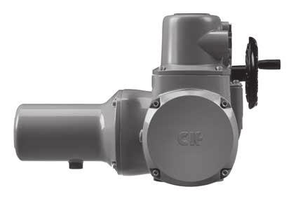
7 4. Actuator Identification 4.1 CK Standard Hand Wheel Conduit Entries Switch Mechanism Cover Protective Earth Connection (M6x1p x 10 Deep) Plug and socket housing Motor Hand / Auto lever Name Plate Electric Actuator Nameplate The actuator name plate will enable you to identify your unit. Example below: Mark Description 1 Facility Address 2 Actuator Model 3 Serial Number 4 Maximum Torque 5 Minimum Torque 6 Output Speed (RPM) 7 Lubricant 8 Temperature Range 9 Manufacturing Date 10 Enclosure Rating 11 Unit Barcode (Factory Use) 12 QR Code 13 Flange Size 14 Maximum Unit Weight 15 Spare Line (Tag Information) 7
8 4.2 CKc Centronik Centronik Name Plate Conduit Entries Protective Earth Connection (M6x1p x 10 Deep) Switch Mechanism Cover Plug and socket housing Motor Centronik Interface Hand / Auto lever Hand Wheel Centronik Module Nameplate The Centronik name plate will enable you to identify your unit. Example below: Mark Description 1 Model 2 Serial Number 3 Main Power Supply 4 Remote Control Supply 5 Internal Customer Supply 6 Backup Supply 7 Maximum Power Rating 8 Customer Wiring Diagram 9 Internal Unit Diagram 10 Temperature Range 11 Enclosure Rating 12 Manufacturing Date 13 Unit Barcode (Factory Use) 14 QR Code 15 Capacitor Value (1ph only) 16 Spare Line (Tag Information) 8
.")
 Pull out the drive bush (3) complete with the bearing assembly (4) CAUTION: Failure to remove the bearing assembly and the o-rings prior to")
9 5. Preparing the Drive Bush 5.1 Drive Bush - Type A Coupling: Please see Publication PUB for thrust/torque allowances. 1 (Note: CK30/60 actuators may be fitted with a F07/FA07 flange adaptor, in which case this will need to be removed before the below procedure is carried out). Turn the actuator onto its side, removing the hex head screws holding the thrust base (1) onto the actuator. Remove the two M3 cap screws retaining the spigot ring (2) Pull out the drive bush (3) complete with the bearing assembly (4) CAUTION: Failure to remove the bearing assembly and the o-rings prior to machining may result in damage to the bearing. Disassembly of bearing assembly: Locate and remove the snap ring (5) using a suitable tool Remove the split collar (6) If fitted, remove the spacer ring (7) Slide the bearing (4) off the drive bush (3) 3 Keep the bearing and the drive bush components clean. The split collar keys (6) must be kept as a machined pair. Machine the drive bush, after removing the o-rings, allowing clearance for rising spindle applications. 2 Reassembly of bearing assembly: Ensure the drive bush (3) is clean and free from swarf. Ensure the o-rings are clean and greased (see section 11, page 26 for typical grease). Slide the bearing assembly (4) onto the drive bush (3) and ensure that it is fitted down to the shoulder. Grease and refit the split collar keys (6) and spacer ring (7) if fitted and secure with the snap ring (5). Grease and re-fit the drive bush bearing assembly into the thrust base. Refit the thrust base (1) ensuring that the drive dogs on the bush align with the slots in the hollow center column and secure with the hex head screws to the following torque values: See Table A on page 12. 9
 whilst pulling the drive bush (2) out.")

10 5.2 Drive Bush - Type B Coupling: Please note: Type B couplings are NOT suitable for axial loads/ forces Turn the actuator onto its side. Type B3 and B4 : Using a suitable tool, remove the circlip (1) whilst pulling the drive bush (2) out. The drive bush will detach from the center column, leaving circlip (3) behind. Type B1 : 3 This drive bush is supplied as an integral part of the actuator. Reassembly: Refitting is the reverse of removal ensuring that the drive bush is greased and the bolts are tightened to the correct torque, see Table A on page


11 6. Mounting the Actuator CAUTION: Do not lift the actuator/valve combination via the actuator. Always lift the combination via the valve. Each lift must be assessed on an individual basis. WARNING: Always ensure that the actuator weight is supported from the actuator body and not the Centronik control module. WARNING: Ensure the actuator is fully supported until full valve/gearbox engagement is achieved and the actuator is secured onto the flange. Ensure the valve is secure before fitting the actuator as the combination may become unstable. If it is necessary to lift the actuator using mechanical equipment, certified slings should be used. Lifting and slinging should always be carried out by competent trained personnel. The actuator base dimensions/couplings conform to ISO 5210 or USA Standard MSS SP102. Actuator to valve fixing must confirm to Material specification ISO Class 12.9, yield strength 1,080 N/mm Weights and Measures Weight - kg (lbs) Frame Size Gross 30/60 33 (73) (87) 250/ (174) Note: Weight stated are the maximum possible within that model range. Oil Capacity Frame Size Litres Pt-US 30/ /


12 6.2 Mounting the Actuator - Rising Stem Valves Fitting the Actuator and Base as a combined unit - all sizes Fit the machine drive bush as described in section 5.1 into the thrust base assembly. 6.5 Actuator Sealing Ensure that the sealing cap and o-ring assembly is securely fitted to prevent moisture ingress into the centre column of the actuator. Lower the actuator onto the threaded valve stem, engage HAND operation and wind the handwheel in the open direction to engage the drive bush onto the valve stem. Continue winding the handwheel until the actuator is firmly down on the valve flange. Continue winding for a further two turns and secure with bolts, tightening down to the listed torques - Table A. Fitting thrust base to valve - all sizes Fit the machine drive bush as described in section 5.1 into the thrust base assembly. Remove the thrust base as described in section 5.1 and place it on the threaded valve spindle with the drive keys pointing uppermost and turn the thrust base in the open direction to engage it on the spindle. Continue turning until the thrust base is on the valve flange but do not tighten at this stage. For valves with rising spindles, a cover tube may be fitted. Ensure that the o-ring is correctly fitted and that the cover tube is secured with the supplied fasteners. Lower the actuator onto the thrust base and rotate the complete actuator until the drive keys on the drive bush align with the slots on the base of the center column. Continue to turn the actuator until the fixings holes align with the thrust base. Replace the base bolts and tighten to the required torque - Table A. Open the valve by two turns and secure the thrust base to the valve flange and tighten to the required torque - Table A. 6.3 Mounting the Actuator - Non rising stem valves - Top Mounted Ensuring that that the drive bush fits the input shaft/key and has adequate axial engagement then fit into the actuator as described in section 5.1/5.2 Engage HAND, offer up the actuator to the valve, turning the handwheel to align the drive bush. Tighten the mounting bolts to the required torque - Table A. Note: When the thrust is being taken in the actuator, a thrust nut must be fitted above the drive bush and securely tightened. 6.4 Mounting the Actuator - Valve with Gearbox - Side Mounted Follow the instructions in 6.3 as for top mounted instructions, checking that the mounting flange is at right angles to the shaft before installation. Table A: Required Torque Imperial Size Imperial Size Nm lbf.ft 1/ / / / / / / Metric Size M M M M M M

13 7. Cable connections 7.1 Terminal block layout WARNING: Ensure all power supplies are isolated before removing any covers. Do NOT run the actuator to limits with Incorrect phase rotation. Safety Instructions in Section 2 of this document must be observed and only persons competent by virtue of their training and experience should carry out electrical connection. For unit specific wiring, please refer to the provided wiring diagram. These can also be downloaded from WARNING: For units including an internal heater. It is important to isolate the heater supply when heating is not required. Electric motor nameplate The current, mains voltage and mains frequency must match the data on the motor name plate: Mark Description 1 Motor QR Code 2 Enclosure Rating 3 Motor Insulation Class 4 Cos ф Power Factor 5 Duty Rating 6 Capacitor Value 7 Serial Number 8 Supply Voltage 9 Nominal Power 10 Nominal Current 11 Temperature Range 12 Unit Barcode (Factory Use) 13
14 7.1 Terminal block layout contd. A switch or circuit breaker must be included in the wiring installation to the actuator. The switch or crcuit breaker must meet the relevant requirements of IEC and IEC and be suitable for the application. The switch or circuit breaker must not disconnect the protective earth conductor. The switch or circuit breaker must be mounted as close to the actuator as possible and shall be marked to indicate that it is the disconnect device for that particular actuator. WARNING: The actuator must be protected with overcurrent protection devices, see relevant Motor Performance data sheet. CAUTION: Power supply cables must have sufficient mechanical protection properties to meet installation requirements and be screened to comply with EMC requirements of the installed actuator. Suitable methods include armoured and/or screened cables or cables contained within conduit. IP68 sealing protection can only be achieved by ensuring that the correct cable glands are fitted and any remaining entries are correctly sealed up. 7.2 Earth/Ground Connections WARNING: Risk of Electric Shock - Do not operate the actuator with the protective Earth conductor disconnected 8. Operating your actuator 8.1 Operating by Hand CAUTION: Under no circumstances should any additional lever device such as a wheel-key or wrench be applied to the handwheel in order to develop more force when closing or opening the valve as this may cause damage to the valve and/ or actuator or may cause the valve to become stuck in the seated/backseated position. Keep clear of the handwheel when engaging hand operation. Actuators driving valves via extension shafts may be subject to retained shaft torsion which can cause the handwheel to rotate when hand operation is engaged. To engage handwheel drive depress the Hand/Auto lever into Hand position and turn the handwheel to engage the clutch. The lever can now be released, it will return to its original position. The handwheel will remain engaged until the actuator is operated electrically when it will automatically disengage and return to motor drive. For local lockout purposes the Hand/Auto lever can be locked in either position using a padlock with a 6.5 mm hasp. Locking the lever in the "hand" position prevents electrical movement. The actuator is supplied with two earthing points. A 6 mm diameter hole is tapped adjacent to the conduit entries on the main casting for attachment of an external protective earthing strap. An internal 6 mm earth connection is also provided however it must not be used alone as the protective Earth Connection. 7.3 Removing the plug and socket Using a 5 mm Allen (Hex) key, loosen the 4 captive screws evenly and remove the cover. Do not attempt to lever off the cover as you may damage the o-ring seal. 7.4 Cable entry The cable entries into the plug and socket are M20 x 1.5p, M25 x 1.5p and M32 x 1.5p. Remove the plastic transit plugs and make cable entries appropriate to the cable type and size. Ensure that threaded adaptors, cable glands or conduit are tight and fully waterproof. Seal unused cable entries with steel or brass threaded plugs. Ensure that the cables are of the appropriate rating for the required duty and are fastened to the correct terminal. Connection details can be found on the wiring diagram. Cable Size: Power Terminals 1,2 and 3: Max 6 mm² PE connection: Max 6 mm² Control contacts: (4-50) Max 2.5 mm² 14
15 9. Commissioning 9.1 Centronik Interface A B IrCK Transmitter / Receiver Open A B C D E F Close Remote Stop Local OPEN LIM DEMO C D E F B C A Bluetooth Connection B Infrared Connection C Configuration Mode A IrCK D Communication Feedback E Valve Position F Current Menu F SETTINGS G Sub Menu / Setting Value LIMITS D E G 15

16 Centronik Navigation The Centronik Control Module can be configured using 2 different input methods. An optional Bluetooth Setting Tool provides a handheld solution compatible with Infrared or optional Bluetooth communication. Alternatively the local selector knobs can be used to navigate in the same way. Be sure to read and understand the equivalent input commands. Instructions included in this manual are provided as shorthand symbols shown below. Local Selector input Setting Tool Input Navigate to previous item within the current menu / decrease value / toggle setting Exit to previous menu / exit setting change Navigate to next item within the current menu / increase value / toggle setting Enter menu / confirm selection / edit setting / save setting value 16

17 Interface Feedback The Centronik display interface includes various features that provide feedback to the operator. This ensures that changes to the configuration of the actuator can be confirmed and validated during the commissioning process. Arrow Identification During general menu navigation, each submenu/setting will have a set of behaviour arrows associated with it. This lets the operator know what can be achieved on the current screen. Solid blocks on the setting indicate you are in viewing mode. Arrows on the setting/menu indicate navigation is possible - both directions. This indicates you are presently at the first menu choice or lowest setting value. This indicates you are presently at the last menu choice or highest setting value. This indicates the setting is read only or only has one possible value. Current Value Both Directions First Menu Last Menu Read Only Confirmation Feedback Whilst modifying settings or navigating through the various Centronik interface menus, it is important to recognise that a change has been accepted or saved. A small confirmation dot will be shown in the top right corner of the display if a valid input command has been recognised by the Centronik interface. For each movement, the confirmation dot will only be shown once the Open/Close selector returns to the default rest position. CLOSELIM DEMO 9.2 Basic Mechanical Switch Mechanism Setting Instructions WARNING: Isolate all power to the actuator unless explicitly instructed otherwise. Remove the 4 x M6 cap screws retaining the switch mechanism cover. Note: Consult wiring to determine specification of switches fitted. Torque/Limit Setting Refer to valve manufacturer for recommended setting. In the absence of valve manufacturer instruction refer to the table below. Valve Type Close Action Open Action Wedge Gate Torque Limit Globe Torque Limit Butterfly Limit Limit Through Conduit Limit Limit Ball Limit Limit Plug Limit Limit Sluice Limit Limit Penstock Limit Limit Parallel Slide Limit Limit 17
 is determined by the set of switches cabled to the controlling switch gear - refer to")
 is determined by the [ACTION] setting within the Centronik Control Module configuration.")

 - by moving the cam using a screwdriver on the adjustment point. CAUTION: To avoid introducing an offset to the set value when adjusting the torque trip limits.")
18 A 5mm Allen (Hex.) key and 0.8 x 4mm flat screwdriver are required to perform commissioning of the CK Mechanical Switch Mechanism. A CAUTION: For CK Standard and CKR actuators, the required end of travel action (torque or position) is determined by the set of switches cabled to the controlling switch gear - refer to actuator terminal plan and site field wiring. B WARNING: For CKC and CKRC actuators, the required end of travel action (torque or position) is determined by the [ACTION] setting within the Centronik Control Module configuration. Set Torque Limits A Indicator/Adjustment Point B C Torque Cam Clutch Screw Open Torque Adjustment Point C D D Close Torque Adjustment Point E Factory Calibration Fixings CAUTION: Do not adjust the fixings or position of the yellow torque indicator plates. These are factory configured and should not be removed under any circumstance. E 1) Move the valve to a mid-travel position and loosen the Torque Cam Clutch 1.5 turns using a flat screwdriver. 2) Adjust each Torque Cam to the desired value - between min. (40%) & max. (100%) - by moving the cam using a screwdriver on the adjustment point. CAUTION: To avoid introducing an offset to the set value when adjusting the torque trip limits. Ensure the screwdriver remains perpendicular to the switch mechanism faceplate. 3) Tighten the Torque Cam Clutch Screw once both torque trip limits have been set. CAUTION: Tighten the Torque Cam Clutch Screw until the spring washer is fully deformed under the screw head. 18
 Move the actuator to the valve CLOSED position using the handwheel.")
 The CLS Adjustment Screw must now be rotated to engage the closed limit switch inside the switch mechanism. The CLS Indicator Window will show one of four possible symbols.")
 Depending on where the mechanism is in the cycle, it is possible that the switch will be approached from the wrong direction, in this case it is necessary to move through the limit and approach it")
 It is necessary to confirm the switch has engaged correctly. a. For CK Standard or CKR units, measure across the appropriate terminals using a continuity meter - 12 & 13 for motor control and 14 & 15 for indication feedback.")
19 Set Position Limits F OLS Indicator Window G OLS Adjustment Screw H Drive Clutch Shaft F I J CLS Indicator Window CLS Adjustment Screw G I CAUTION: The main power supply must be maintained during the commissioning process for CKC and CKRC actuators with fitted Centronik Control Modules. H J 1) Move the actuator to the valve CLOSED position using the handwheel. 2) Using a flat screwdriver, depress the Drive Clutch Shaft and rotate to the Set position as shown on the switch mechanism faceplate. OLS CLS 3) The CLS Adjustment Screw must now be rotated to engage the closed limit switch inside the switch mechanism. The CLS Indicator Window will show one of four possible symbols. Refer to Figure 1 on page 20. 4) Depending on where the mechanism is in the cycle, it is possible that the switch will be approached from the wrong direction, in this case it is necessary to move through the limit and approach it from the correct direction. This avoids the need to wind through the whole mechanism to reach the limit position. The correct direction to approach the limit is shown by the arrow next to the Adjustment Screw input. 5) It is necessary to confirm the switch has engaged correctly. a. For CK Standard or CKR units, measure across the appropriate terminals using a continuity meter - 12 & 13 for motor control and 14 & 15 for indication feedback. b. For CKC or CKRC units fitted with a Centronik control Module, confirm the position display shows the closed limit symbol. 6) Using a flat screwdriver, depress the Drive Clutch Shaft and rotate to the Run position as shown on the switch mechanism faceplate. CLOSELIM DEMO 7) Rotate the CLS and OLS Adjustment Screws a small amount in both directions to re-engage the mechanism drive. A click will be heard as the drive drops back into engagement and the adjustment screws will no longer move in either direction. CAUTION: This must be done or the limit will be lost when the actuator is moved. 19
20 8) Move the actuator to the valve OPEN position using the handwheel. 9) Using a flat screwdriver, depress the Drive Clutch Shaft and rotate to the Set position as shown on the switch mechanism faceplate. OLS CLS 10) The OLS Adjustment Screw must now be rotated to engage the open limit switch inside the switch mechanism. The OLS Indicator Window will show one of four possible symbols. Please refer to Figure 1 below for direction input. 11) Depending on where the mechanism is in the cycle, it is possible that the switch will be approached from the wrong direction, in this case it is necessary to move through the limit and approach it from the correct direction. This avoids the need to wind through the whole mechanism to reach the limit position. The correct direction to approach the limit is shown by the arrow next to the Adjustment Screw input. 12) It is necessary to confirm the switch has engaged correctly. a. For CK Standard or CKR units, measure across the appropriate terminals using a continuity meter - 16 & 17 for motor control and 18 & 19 for indication feedback. b. For CKC or CKRC units fitted with a Centronik control Module, confirm the position display shows the open limit symbol. 13) Using a flat screwdriver, depress the Drive Clutch Shaft and rotate to the Run position as shown on the switch mechanism faceplate. OPEN LIM DEMO 14) Rotate the OLS and CLS Adjustment Screws a small amount in both directions to re-engage the mechanism drive. A click will be heard as the drive drops back into engagement and the adjustment screws will no longer move in either direction. CAUTION: This must be done or the limit will be lost when the actuator is moved. OLS CLS OLS CLS Rotate the OLS/CLS Adjustment Shaft Clockwise. Rotate the OLS/CLS Adjustment Shaft Anti-Clockwise. OLS CLS OLS CLS Rotate the OLS/CLS Adjustment Shaft in the direction shown next to the Shaft input. The limit switching point is near or made. Figure 1. 20
21 End of Travel Action For CKC or CKRC actuators fitted with a Mechanical Switch Mechanism, the required end of travel action (torque or position) is determined by the [ACTION] setting within the Centronik configuration. All other limit functions will not be available as they need to be intrusively set on the mechanism. USER X MAIN.MENU LANGUAGE SETTINGS LIMITS CLOSE.SET ACTION OPEN.SETT. ACTION Password Entry Process Main menu Language Settings Limit settings Close settings Stop on Position or Torque Open settings Stop on Position or Torque 21


22 9.3 Basic Digital Switch Mechanism Setting Entering Configuration mode Access to configuration mode will vary depending on the navigation method employed. To access configuration mode with the local selector, ensure the actuator is in Stop mode and input the following sequence: Each command input must be completed within 1 second of the last and the selector knob must return to its default rest position between each input. To access configuration mode with the Bluetooth Setting Tool, ensure the actuator is in Stop mode and point the setting tool directly at the IrCK LED. Press to initiate communication. The IrCK symbol will be shown when an input from the Bluetooth Setting Tool is registered by the Centronik Control Module. If the optional Bluetooth module is fitted, the Setting Tool will begin communication through IrCK until a secure Bluetooth link has been established. To confirm a Bluetooth connection has been successful, the top left symbol on the Centronik display will change from IrCK to and the Bluetooth Setting Tool button will illuminate solid blue. For IrCK communication, the Bluetooth Setting Tool must be aligned to the IrCK LED at all times. Entering the User Password The password entry screen will be displayed with the default password visible. Press to confirm this entry or use to enter a different password. For instruction on changing the user password, refer to PUB PASSWORD ROTORKOO Blank spaces will fill with whilst modifying the password text. Once a valid password has been entered the display will show the current active permission level with a symbol and text. Press to return to the main menu. Actuator settings cannot be modified in Remote. The symbol shown to the left side of the display will reference the following permission levels: User level permission to provide basic access to settings for commissioning and configuration purposes. Super User level permission to provide access to more advanced setting features. PASSWORD USER x Service level permission for Engineer access only. 22
23 Menu Navigation The menu map below provides direction for the basic setting and commissioning of a CKC or CKRC actuator equipped with a Digital Switch Mechanism and Centronik Control Module. USER X MAIN.MENU LANGUAGE SETTINGS LIMITS CLOSE.SET DIRECTION ACTION SEAT.TORQ SET.LIMIT. OPEN.SETT. ACTION SEAT.TORQ. SET.LIMIT. TURNS TRQ.LIM.BP. OPENING OP.BP.POSI. CLOSING CL.BP.POSI. Password Entry Process Main menu Language Settings Limit settings Close settings Direction to close Stop on Position or Torque Torque Limit Value Set End of Travel Position Open settings Stop on Position or Torque Torque Limit Value Set End of Travel Position Total Travel Turns Torque Limit Bypass Enable in the Open Direction Opening Bypass Position Value Enable in the Close Direction Closing Bypass Position Value 23
24 Main Menu > Settings > Limits The Limits menu details all of the appropriate settings to control the conditions for stopping actuator movement. Use the menu map on the previous page to follow the menu structure through to the [LIMITS] sub menu. Limits > Close Settings [CLOSE.SET.] Direction to Close [DIRECTIO.] Press to edit, select preferred option using and for Clockwise or Anti-clockwise operation and press to save selection. Action [ACTION] Press to edit, select preferred option using and for Seat Limit or Seat Torque and press to save selection. Seating Torque [SEAT.TORQ.] Press to edit, adjust shown value using and and press to confirm selection (40% - 100%). CAUTION: The Seating Torque value is used as torque limit protection through full valve travel. Setting the Close Position Limit [SET.LIMIT.] Move the actuator to the fully closed position. Allow for overrun by winding the manual override handwheel in the open direction by 5 turns (10 turns for CK500). Limits > Open Settings [OPEN.SETT.] Action [ACTION] Press to edit, select preferred option using and for Seat Limit or Seat Torque and press to save selection. Seating Torque [SEAT.TORQ.] Press to edit, adjust shown value using and and press to confirm (40% - 100%). CAUTION: The Seating Torque value is used as torque limit protection through full valve travel. Turns [TURNS] This setting will show the number of output turns configured for actuator / valve travel between the open and closed limit positions. This is a read only function to validate total valve travel. Setting the Open Position Limit [SET.LIMIT.] Move the actuator to the fully open position. Allow for overrun by winding the manual override handwheel in the close direction by 5 turns (10 turns for CK500). Press to edit. [SURE??] will show on the display, press to confirm. Once these steps are complete, the Centronik display position should replicate the image below. Press to edit. [SURE??] will show on the display, press to confirm. Once these steps are complete, the Centronik display position should replicate the image below. CLOSELIM DEMO OPEN LIM DEMO 24
![Limits > Torque Limit Bypass [TRQ.LIM.B.P.] Occasionally applications will require a break to open or break to close torque that exceeds the standard torque limit.](/docs-images/88/117517882/images/25-0.jpg "Setting the torque limit bypass will ignore existing torque limit settings and apply maximum torque (up to approximately 150% or rated) across a predetermined portion of travel.")

25 Limits > Torque Limit Bypass [TRQ.LIM.B.P.] Occasionally applications will require a break to open or break to close torque that exceeds the standard torque limit. Setting the torque limit bypass will ignore existing torque limit settings and apply maximum torque (up to approximately 150% or rated) across a predetermined portion of travel. CAUTION: The valvemaker / integrator should be consulted to confirm the valve structure and interface components can withstand the additional torque/thrust. Torque Limit Bypass The [OPENING] and [CLOSING] settings will enable torque limit bypass for the relevant direction of travel, use and to enter the setting sub menu. Torque Limit Bypass Position The [OP.BP.POSI.] value dictates the travel away from the closed position limit that the torque limit will be bypassed in the open direction. Press to edit, adjust shown value using and and press to save selection. E.g. setting at 5% will bypass the torque limit between 0% and 5%. The [CL.BP.POSI.] value dictates the travel away from the open position limit that the torque limit will be bypassed in the close direction. Press to edit, adjust shown value using and and press to save selection. E.g. setting at 95% will bypass the torque limit between 95% and 100%. Press to edit, select [ON] or [OFF] and press to save selection. PASSWORD USER x 25
26 9.4. Secondary Function Setting CK Range actuators can be provided with optional add-ons that provide extra functionality. For instruction on setting secondary functions, please refer to the following documents which are available on CK Standard and CKR - refer to PUB CKC and CKRC - refer to PUB Maintenance, Monitoring and Troubleshooting Routine Maintenance should include the following : Check actuator to valve fixing bolts for tightness. Ensure valve stems and drive nuts are clean and properly lubricated. If the motorized valve is rarely operated, a schedule of operation should be set up. Check the actuator for damage, loose or missing fixings. Ensure that there is not an excessive build up of dust or contaminate on the actuator. 11. Disposal / Recycling User advice on disposal of your product at the end of its life. Please see table below. In all cases check local authority regulation before disposal. Oil : Unless specially ordered for extreme climatic conditions, actuators are dispatched with gearcases filled with SAE 80EP oil suitable for ambient temperatures ranging from -22 to 160 F (-30 to 70 C). Base assembly : O-rings grease: Multis EP2 / Lithoshield EP2 or equivalent for all temperature ranges. Subject Definition Remarks / examples Hazardous Recyclable EU Waste Code Printed circuit boards All Products Yes Yes Electrical & Electronic Wire All Products Yes Yes Disposal Use specialist recyclers Metals Aluminium Gearcases and covers No Yes Copper/Brass Wire, gears, motor windings No Yes Zinc CK clutch Ring and associated components No Yes Iron/Steel Gears and bases No Yes Mixed Metals CK motor rotors No Yes Use licensed recyclers Plastics Glass filled nylon Electronics chassis No No Disposal as general commercial waste Unfilled Gears, Window, Blanking plug No Yes Use specialist recyclers Oil /Grease Mineral Gearbox lubrication Yes Yes Food Grade Gearbox lubrication Yes Yes Grease Handwheel Yes No Will require special treatment before disposal, use specialist recyclers or waste disposal companies Rubber Seals & Orings Cover and shaft sealing Yes No May require special treatment before disposal, use specialist waste disposal companies 26
27 12. Environmental Standard CK actuators are suitable for applications where vibration and shock severity does not exceed the following: Plant induced Vibration: 1g rms total for all vibration within the frequency range of 10 to 1000 Hz Shock: Watertight: Temperature: 5g peak acceleration IP68 EN (8 metres for 96 hours) -30 to +70 C (-22 to +158 F) 27
28 A full listing of our worldwide sales and service network is available on our website. Rotork plc Brassmill Lane, Bath, UK tel +44 (0) fax +44 (0) mail@rotork.com Rotork is a corporate member of the Institute of Asset Management PUB Issue 01/17 As part of a process of on-going product development, Rotork reserves the right to amend and change specifications without prior notice. Published data may be subject to change. For the very latest version release, visit our website at The name Rotork is a registered trademark. Rotork recognizes all registered trademarks. Published and produced in the UK by Rotork Controls Limited. POWTG0117
ROM Series. Keeping the World Flowing. Installation Manual. Valve Actuators
 ROM Series Installation Manual Valve Actuators Keeping the World Flowing Contents Section Page Health and safety 3 Storage 4 Mounting the actuator 4 Setting the actuator stop bolts 5 Cable connections
ROM Series. Established Leaders in Flow Control. Installation Manual. Valve Actuators
 ROM Series Installation Manual Valve Actuators Established Leaders in Flow Control Contents Section Page Health and Safety 3 Storage 4 Mounting the actuator 4 Setting the actuator stop bolts 5 Cable connections
CK Range. Keeping the World Flowing. Spare Parts Manual. Modular Design Electric Valve Actuators
 CK Range Spare Parts Manual Modular Design Electric Valve Actuators Note: Full details from the actuator nameplate must be given when enquiring about or ordering spare parts Spare Parts Manual for CK Range
ROMpak Series. Keeping the World Flowing. Installation Manual. Valve Actuators
 ROMpak Series Installation Manual Valve Actuators Keeping the World Flowing Contents Section Page Introduction Health and safety X 3 Section Operating Title by hand Electrical Content operation 4 X5 Indication
Q Range electric direct-drive quarter turn valve actuators. Instruction manual
 Contents Q Range electric direct-drive quarter turn valve actuators Instruction manual Publication number E670E Date of issue 01/07 page 1 Identifying Actuator Parts 2 1.1 Weights 2 2 Mounting Actuator
Gearbox Installation Manual
 Gearbox Installation Manual Rotork Gears IW, MOW, MTW, IB and IS ranges (Electronic copy available on www.rotork.com)! This manual contains important safety information. Please ensure it is thoroughly
Q Range Watertight Single-Phase Electric Quarter-turn Actuators for part-turn valves and dampers
 This brochure provides a comprehensive overview of the applications and associated functions available with Rotork Q actuators - comprising Q Standard and Q Pak actuators. The watertight Q Range actuators
IQTF Range. Keeping the World Flowing. Electric full output turn actuators for choke and control valve applications
 The IQTF actuator, part of the 3 rd Generation IQ actuator range, is engineered for choke and control valve applications. The IQTF provides the reliability, accuracy and high resolution movement required
Gearbox Instruction Manual
 Gearbox Instruction Manual Rotork Gears gearbox ranges IW, MOW, MTW, IB, IS, HOB/MPR & HOS/MPR! This manual contains important safety information. Thoroughly read and understand it before installing the
ROM and ROMpak Range. Quarter-turn Direct Drive Electric Actuators. Established Leaders in Actuation Technology
 ROM and ROMpak Range Quarter-turn Direct Drive Electric ctuators Established Leaders in ctuation Technology Contents Section Page Product Overview 3 Features of the ROM and RM Range 4 Mechanical and Electrical
Contents. AQ Instruction Manual
 Contents AQ Instruction Manual Publication number E570E Date of issue 11/02 (AQ100 AQ300 AQ800) Page 1. Identifying actuator parts 3 2. Actuator mounting 4 2.1 Drive bush 4 2.2 Mounting 4 3. Site cabling
Established Leaders in Valve Actuation CP RANGE COMPACT PNEUMATIC ACTUATORS INSTALLATION AND MAINTENANCE MANUAL. Publication F230E Date of issue 03/08
 Established Leaders in Valve Actuation COMPACT PNEUMATIC ACTUATORS INSTALLATION AND MAINTENANCE MANUAL TABLE OF CONTENTS SECTION CONTENT PAGE Introduction Installation Maintenance 5 4 Grease Specification
Actuator-Gearbox Combination
 Actuator-Gearbox Combination Installation and Maintenance Instructions Keeping the World Flowing Contents Section Page Section Page 1. Introduction 3 2. Health & Safety 4 3. Combination Types 5 4. Storage
OPERATION INSTRUCTONS MODEL SG 05.1 SG Quarter-Turn Actuators
 OPERATION INSTRUCTONS MODEL SG 05.1 SG 12.1 Quarter-Turn Actuators AUMA Actuators, Inc. USA 100 Southpointe Boulevard Canonsburg, PA 15317 724-743-2862 Fax: 724-743-4711 www.auma-usa.com email: mailbox@auma-usa.com
Installation, Operation and Maintenance Manual
 HQ 005. ELECTRIC ACTUATORS QUARTER-TURN ELECTRIC ACTUATORS Installation, Operation and Maintenance Manual s Version Ver. 1 Revision Rev. 1 Document No. HKQI-611 Small & Compact Design High corrosion resistance
VA-908x Series Electric Rotary Actuators for Two-Position and Modulating Service
 VA-908x Series Electric Rotary Actuators for Two-Position and Modulating Service Installation Instructions VA-908x Code No. LIT-12011566 Issued August 24, 2009 Applications The VA-908x Series Electric
DIGITAL BATTERY TORQUE WRENCH (BC-RAD SELECT) USER GUIDE
 USER GUIDE") DIGITAL BATTERY TORQUE WRENCH (BC-RAD SELECT) USER GUIDE W.CHRISTIE (INDUSTRIAL) LTD CHRISTIE HOUSE, MEADOWBANK ROAD, ROTHERHAM, SOUTH YORKSHIRE, S61 2NF, UK T: +44(0)1709 550088 F: +44(0)1709 550030 E:
DIGITAL BATTERY TORQUE WRENCH (BC-RAD SELECT) USER GUIDE W.CHRISTIE (INDUSTRIAL) LTD CHRISTIE HOUSE, MEADOWBANK ROAD, ROTHERHAM, SOUTH YORKSHIRE, S61 2NF, UK T: +44(0)1709 550088 F: +44(0)1709 550030 E:
GT Range. Rack & Pinion Actuators for Rotary Valve Control. Keeping the World Flowing
 GT Range Rack & Pinion Actuators for Rotary Valve Control Keeping the World Flowing Rotork Actuators Quality Controlled Since the company was founded in 1957, Rotork has become the standard for excellence
IQ Range. Instructions for Safe Use, Installation, Basic Setup and Maintenance
 IQ Range Instructions for Safe Use, Installation, Basic Setup and Maintenance This manual contains important safety information. Please ensure it is thoroughly read and understood before installing, operating
HQ Series ¼ Turn Electric Actuator
 HQ Series ¼ Turn Electric Actuator Models HQ008 to HQ300 Operation and Installation Manual HQ Series Operation and Installation Manual 1 Table of Contents: General 1.0 Actuator Mounting 2.0 Power Requirements
OPEN/CLOSE SERVICE ELECTRIC ACTUATORS OPERATION AND MAINTENANCE MANUAL COMMERCIAL AND INDUSTRIAL VALVES AND AUTOMATION
 SERIES 1000-X OPEN/CLOSE SERVICE ELECTRIC ACTUATORS OPERATION AND MAINTENANCE MANUAL COMMERCIAL AND INDUSTRIAL VALVES AND AUTOMATION Publication S1000X-110 VER0215-1 For information on this product and
Series 70 24V On/Off Electric Actuator Operation and Maintenance Manual
 Series 70 Operation and Maintenance Manual TABLE OF CONTENTS 1. Definition of Terms............................................. 1 2. Safety................................................... 1 3. Storage..................................................
Operation & Instructions Manual SA 3 - SA 100 SAR 3 - SAR 100
 Operation & Instructions Manual SA 3 - SA 100 SAR 3 - SAR 100 Warnings and notes Failure to observe the warnings and notes may lead to serious injuries or damage. Qualified personnel must be thoroughly
Series A Electric Linear Actuators
 3581650/3 IM-P358-11 CH Issue 3 Series A Electric Linear Actuators Installation and Maintenance Instructions 1. Safety information 2. General product information 3. Installation 4. Commissioning 5. Maintenance
Milwaukee's Electric Actuator Installation, Operation & Maintenance Manual
 Milwaukee's Electric Actuator Installation, Operation & Maintenance Manual 1 Cover screws 9/64 Allen wrench. Terminal strip screws 1/8 wide flat head screw driver. Mounting pad screws 3/8 socket Cover
Multi-turn actuators SA 07.2 SA 16.2/SAR 07.2 SAR 16.2 with local control unit AUMA SEMIPACT SEM 01.1/SEM 02.1
 Multi-turn actuators SA 07.2 SA 16.2/SAR 07.2 SAR 16.2 with local control unit AUMA SEMIPACT SEM 01.1/SEM 02.1 Operation instructions Assembly, operation, commissioning Table of contents SEM 01.1/SEM 02.1
PN9000 Series Pneumatic Actuators Installation and Maintenance Instructions
 3579049/14 IM-P357-29 CTLS Issue 14 PN9000 Series Pneumatic Actuators Installation and Maintenance Instructions PN9100 PN9200 1. Safety information 2. General product information PN9300 3. Installation
EL5600 Series Electric Linear Actuators Installation and Maintenance Instructions
 3581050/5 IM-P358-05 CH Issue 5 EL5600 Series Electric Linear Actuators Installation and Maintenance Instructions 1 Safety information 2 General 3 Installation 4 Commissioning 5 Maintenance IM-P358-05
GT Range. Rack & Pinion Actuators for Rotary Valve Control. Keeping the World Flowing
 GT Range Rack & Pinion Actuators for Rotary Valve Control Keeping the World Flowing Rotork Actuators Quality Controlled Since the company was founded in 1957, Rotork has become the standard for excellence
GP RANGE PNEUMATIC SCOTCH YOKE ACTUATORS INSTALLATION AND MAINTENANCE MANUAL
 PNEUMATIC SCOTCH YOKE ACTUATORS INSTALLATION AND MAINTENANCE MANUAL CONTENTS SECTION CONTENT PAGE Introduction 3 Installation 3 3 Maintenance 5 4 Grease and Hydraulic Oil Specifications 6 5 Cylinder Seal
AE Installation Operation & Maintenance Instructions
 AE-1400 Installation Operation & Maintenance Instructions IMPORTANT Please read the installation operation and maintenance instruction prior to using any Jomar Valve component. Failure to follow the instructions
Your Global Flow Control Partner. Series 70 24V On/Off Electric Actuator Operation and Maintenance Manual
 Your Global Flow Control Partner Series 70 Table of Contents 1. Definition of Terms.......................................2 2. Safety............................................. 2 3. Storage............................................2
Roto Hammer Range. Chainwheels, Handwheels, Chains and Accessories. Keeping the World Flowing
 Roto Hammer Range Chainwheels, Handwheels, Chains and Accessories Keeping the World Flowing Roto Hammer Range Since 1959 Meeting client needs and exceeding expectations for over 50 years Safe and dependable
HQ Series ¼ Turn Electric Actuator
 HQ Series ¼ Turn Electric Actuator Models HQ004 and HQ006 Operation and Installation Manual HQ Series Operation and Installation Manual REV B 27-02-2012 1 Table of Contents: General 1.0 Actuator Mounting
IQS and IQSL Range. Electrical Data Single-Phase Power Supplies. Keeping the World Flowing
 IQS and IQSL Range Electrical Data Single-Phase Power Supplies Keeping the World Flowing Contents Section Page Introduction 3 Electrical Consumption Data 50 Hz 115 V 5 230 V 5 60 Hz 115 V 6 230 V 6 Rotork
GH RANGE HYDRAULIC SCOTCH YOKE ACTUATORS INSTALLATION AND MAINTENANCE MANUAL. Publication F131E Date of issue 04/08
 HYDRAULIC SCOTCH YOKE ACTUATORS INSTALLATION AND MAINTENANCE MANUAL Publication F3E TABLE OF CONTENTS SECTION CONTENT PAGE Introduction 3 Installation 3 3 Maintenance 5 4 Grease and Hydraulic Oil Specifications
Q Range. Watertight Single-Phase Electric Quarter-turn Actuators for part turn valves and dampers. Established Leaders in Valve Actuation
 Electric Actuators and Control Systems Established Leaders in Valve Actuation Q Range Watertight Single-Phase Electric Quarter-turn Actuators for part turn valves and dampers Publication E610E Issue 03/08
Pan and Tilt Head CDD2416-T
 Pan and Tilt Head CDD2416-T Installation guide Before attempting to connect or operate this product, please read these instructions completely Williams Electronics Ltd www.w-e.co.uk Tel: +44 (0)2921 660
GT Range. Rack & Pinion Actuators for Rotary Valve Control. Keeping the World Flowing
 GT Range Rack & Pinion Actuators for Rotary Valve Control Keeping the World Flowing Rotork Actuators Quality Controlled Since the company was founded in 1957, Rotork has become the standard for excellence
Part-turn actuators SQ 05.2 SQ 14.2/SQR 05.2 SQR 14.2 with actuator controls AUMA MATIC AM 01.1
 Part-turn actuators with actuator controls AUMA MATIC AM 01.1 Operation instructions Assembly, operation, commissioning Table of contents AM 01.1 Read operation instructions first. Observe safety instructions.
Accessories for Wind Power Inverter WINDY BOY PROTECTION BOX 400 / 500 / 600
 Accessories for Wind Power Inverter WINDY BOY PROTECTION BOX 400 / 500 / 600 Installation Guide WBP-Box-IEN103320 IMEN-WBP-BOX Version 2.0 EN SMA Solar Technology AG Table of Contents Table of Contents
Installation and maintenace instructions
 range Installation and maintenace instructions Publication E170E date of issue 8/98 This instruction manual provides instruction on :- * Manual and electrical (local and remote) operation. * Preparation
IQ Range. Instructions for Safe Use, Installation, Basic Setup and Maintenance
 IQ Range Instructions for Safe Use, Installation, Basic Setup and Maintenance This manual contains important safety information. Please ensure it is thoroughly read and understood before installing, operating
Series 10 Actuator. Installation, Operation and Maintenance Manual
 Series 10 Actuator Installation, Operation and Maintenance Manual File: series10.man Location: assembly/manual Rev.E 6/24/14 Page 1 of 8 Table of Contents Series 10 Electric Actuator Introduction... 3
AWT Range. Watertight 3-phase Electric Valve Actuator. Redefining Flow Control
 AWT Range Watertight 3-phase Electric Valve Actuator Redefining Flow Control Contents Section Page Product Overview 3 Application 4 Reliability Through Sealing 4 Reliability Through Control 5 Reliability
Actuator-Gearbox Combination
 Actuator-Gearbox Combination Installation and Maintenance Instructions Keeping the World Flowing Contents Section Page Section Page 1.0 Introduction 3 2.0 Health and Safety 4 3.0 Combination Types 5 4.0
Part-turn actuators SQ 05.2 SQ 14.2/SQR 05.2 SQR 14.2 with local control unit AUMA SEMIPACT SEM 01.1/SEM 02.1
 Part-turn actuators SQ 05.2 SQ 14.2/SQR 05.2 SQR 14.2 with local control unit AUMA SEMIPACT SEM 01.1/SEM 02.1 Operation instructions Assembly, operation, commissioning Table of contents SEM 01.1/SEM 02.1
AWT Range. Watertight 3-phase Electric Valve Actuator. Established Leaders in Valve Actuation. Electric Actuators and Control Systems
 Electric Actuators and Control Systems Established Leaders in Valve Actuation AWT Range Watertight 3-phase Electric Valve Actuator Publication E310E Issue 09/04 Rotork actuators have been in use all around
Allen-Bradley Parts. CENTERLINE 2500 Motor Control Centers Installing, Joining and Splicing Columns. Installation Instructions. Catalog Number 2500
 Installation Instructions CENTERLINE 2500 Motor Control Centers Installing, Joining and Splicing Columns Catalog Number 2500 Topic Page Important User Information 2 Location Planning 3 Environment 3 Removal
BR 31a Rack-and-pinion Actuator,
 Operating, assembly and maintenance instructions BR 31a Rack-and-pinion Actuator, SRP and DAP 1. General These instructions are intended to support the user in the assembly, maintenance, and repair of
Multi-turn actuators SAEx 07.2 SAEx 16.2 SAREx 07.2 SAREx 16.2 with actuator controls AUMA MATIC BASIC AMBExC01.1
 Multi-turn actuators SAEx 07.2 SAEx 16.2 SAREx 07.2 SAREx 16.2 with actuator controls AUMA MATIC BASIC AMBExC01.1 Operation instructions Assembly, operation, commissioning Table of contents AMBExC01.1
Instructions for installation, operation and maintenance of: GATE VALVE
 Instructions for installation, operation and maintenance of: GATE VALVE GEN GAC GAF/GENF TERMOVENT SC Temerin Republic of Serbia Instruction for installation, operation and maintenance: Table of Contents
Current consumption Auxiliary switch. Angle of rotation 90 (internal electrical stops) Running time
 Running time") Technical data sheet Rotary actuator SY-4--T Rotary actuators for butterfly valves Torque 50 Nm Nominal voltage AC 4 V Control: Open-close or -point Auxiliary switch Technical data Electrical data Nominal
Technical data sheet Rotary actuator SY-4--T Rotary actuators for butterfly valves Torque 50 Nm Nominal voltage AC 4 V Control: Open-close or -point Auxiliary switch Technical data Electrical data Nominal
Electric part-turn actuators
 Electric part-turn actuators Positron II 504-524 Positron III 704-724 Operation Instructions Scope of these instructions: These instructions are valid for part-turn actuators of the type ranges Positron
Radius, LLC Electric quarter turn actuator EW series Installation, Maintenance and Operating Manual
 Radius, LLC Electric quarter turn actuator EW series Installation, Maintenance and Operating Manual Models EW-880, 1400, 2100, 3100, 4400, 7000, 9700, 13000, 17000, 26500 EW-IMO-04 Radius, LLC 4922 Technical
DC Master 24/ A
 USERS MANUAL DC Master 24/12 50-60A DC-DC converter MASTERVOLT Snijdersbergweg 93, 1105 AN Amsterdam The Netherlands Tel.: +31-20-3422100 Fax.: +31-20-6971006 www.mastervolt.com ENGLISH Copyright 2015
Technical Specification. RCS Electric Actuators with a ProfiBus Field Control and Communication Module
 The following specification defines the minimum requirements for the supply of motor operated valve actuators with a field communication bus system for remote control. The complete system shall consist
GuaRdboX - Gd series IOM (Installation, Operation & Maintenance Manual) 0100-ENG rev.4
 0100-ENG rev.4") 1. Introduction: This instruction manual contains important information regarding the safety instructions, installation, operation, maintenance and storage of the Guardbox limit switch boxes. The limit
1. Introduction: This instruction manual contains important information regarding the safety instructions, installation, operation, maintenance and storage of the Guardbox limit switch boxes. The limit
 AUTOGARD SERIES 820 TORQUE LIMITER Installation and Maintenance Manual DB0009 Issue 11 21 Feb 2017 British Autogard Ltd 2 Wilkinson Rd., Love Lane Industrial Estate, Cirencester, Glos., GL7 1YT UK Tel.
Electric Actuator Installation, Operation & Maintenance Manual
 Electric Actuator Installation, Operation & Maintenance Manual For Use with: All Standard AC Voltage Models Additional supplements may be needed for selected optional equipment including, but not limited
Installation, Operation, and Maintenance Manual
 Industrial Process Installation, Operation, and Maintenance Manual Cam-Tite Ball Valve Table of Contents Table of Contents Introduction and Safety...2 Safety message levels...2 User health and safety...2
HPG Range. Direct High-Pressure Gas Valve Actuators. Redefining Flow Control
 PG Range Direct igh-pressure Gas Valve Actuators Redefining Flow Control Rotork Actuators Quality Controlled Rotork is a global leader in valve actuation technology. We provide a comprehensive range of
Installation, Operation, and Maintenance Manual
 Industrial Process Installation, Operation, and Maintenance Manual Series PBV Plastic Lined Ball Valve Table of Contents Table of Contents Introduction and Safety...2 Safety message levels...2 User health
Instruction Manual. ThinkTop D30 ESE02248-EN Patented Sensor System Registered Design Registered Trademark. Original manual _1
 Instruction Manual ThinkTop D30 2064-0000_1 Patented Sensor System Registered Design Registered Trademark ESE02248-EN3 2014-12 Original manual Table of contents The information herein is correct at the
INSTRUCTIONS FOR USE SPUR GEAR OPERATORS. E. EBONG issue 4 SPUR
 INSTRUCTIONS FOR USE GEAR OPERATORS Spur Range Specification: Installation, Operating and Maintenance Instructions: Assembly and Dismantling Instructions: Spare Parts List and Recommended 5 Years Holding
Multi-turn actuators SAI 07.1 SAI 16.1/SARI 07.1 SARI 16.1 AUMA NORM (without controls) qualified for use in nuclear power plants according to TU
 qualified for use in nuclear power plants according to TU") Multi-turn actuators SAI 07.1 SAI 16.1/SARI 07.1 SARI 16.1 AUMA NORM (without controls) qualified for use in nuclear power plants according to TU 3791-003-38959426-2007 Operation instructions Operation,
Multi-turn actuators SAI 07.1 SAI 16.1/SARI 07.1 SARI 16.1 AUMA NORM (without controls) qualified for use in nuclear power plants according to TU 3791-003-38959426-2007 Operation instructions Operation,
Installation, Operation, and Maintenance Manual
 Industrial Process Installation, Operation, and Maintenance Manual Series PBFV Plastic Lined Butterfly Valve - Lug and Wafer Style Table of Contents Table of Contents Introduction and Safety...2 Safety
Installation, Maintenance and Operation Manual
 Installation, Maintenance and Operation Manual Radius, LLC 4922 Technical Drive Milford, MI 48381 Contents 1. Before operating actuator.. 3 2. About EW actuators 4 1) Internal & external component 2) Internal
Features. Suitable for use in SIL 2 applications. Available in LP low power version with less than 1.65 A current consumption. General application
 The ICON 2000 v4 series are electronically-configurable quarter and multi-turn actuators with advanced operation, control, setting and maintenance characteristics Features General application The ICON
Safe & Secure Series Electric Actuator with Internal Battery Back-up Installation, Operation & Maintenance Manual
 Safe & Secure Series Electric Actuator with Internal Battery Back-up Installation, Operation & Maintenance Manual For Use with: SNS4, SNS6, SNS10 & SNS15 Models Additional supplements may be needed for
WATERFLUX 3070 Quick Start
 WATERFLUX 3070 Quick Start Battery powered electromagnetic water meter Electronic Revision ER 4.3.0_ up to ER 4.3.4_ (SW.REV 4.2.2_ up to 4.2.5_) KROHNE CONTENTS WATERFLUX 3070 1 Safety instructions 4
Multi-turn actuators SAI 25.1 SAI 35.1/SARI 25.1 SARI 30.1 AUMA NORM actuator (without controls) for use in nuclear power plants
 for use in nuclear power plants") Multi-turn actuators AUMA NORM actuator (without controls) for use in nuclear power plants Operation instructions Assembly, operation, commissioning Table of contents for use in nuclear power plants Read
Multi-turn actuators AUMA NORM actuator (without controls) for use in nuclear power plants Operation instructions Assembly, operation, commissioning Table of contents for use in nuclear power plants Read
The EFL 2000/1 & 2 User Guide Test Sieve Shaker. Contents
 The EFL 2000/1 & 2 User Guide Test Sieve Shaker ISSUE 04-02 Contents Description Page 1 Setting Up: 2-8 Unpacking 2 Assembly 3 Clamping Assembly 4 Electrical Connections 5 Sieve Stacking 6 8 Operating
K Range. High Torque Electric Valve Actuators. Redefining Flow Control
 K Range High Torque Electric Valve Actuators Redefining Flow Control Contents Section Page K Range Actuator 3 K Range High Torque Features 4 Enclosure Options Drive Options 6 K Range Performance Summary
Mounting and operating instructions EB 5801 EN. Electric Actuators Type 5801 (Rotary Actuator) Type 5802 (Linear Actuator)
 Type 5802 (Linear Actuator)") Electric Actuators Type 5801 (Rotary Actuator) Type 5802 (Linear Actuator) Linear Actuator with Type 3260 Control Valve Rotary actuator with lever system Linear actuator with Type 3321 (V2001) Control
Electric Actuators Type 5801 (Rotary Actuator) Type 5802 (Linear Actuator) Linear Actuator with Type 3260 Control Valve Rotary actuator with lever system Linear actuator with Type 3321 (V2001) Control
Model DFR 070/156/220 Rotary Actuator
 Figure 1 DFR 156 TABLE OF CONTENTS General 2 Actuator Assembly 18 Scope 2 Bushing / Yoke Assembly 18 Principles of Operation 2 Spring Barrel Assembly 18 Safety Caution 2 Diaphragm Plate Assembly 20 Specifications
Installation and Operational Instructions for EAS - HTL housed overload clutch Sizes 01 3 Type 490._24.0
 Please read these Operational Instructions carefully and follow them accordingly! Ignoring these Instructions may lead to malfunctions or to clutch failure, resulting in damage to other parts. Contents:
GO Range. Gas-over-Oil Valve Actuators. Redefining Flow Control
 GO Range Gas-over-Oil Valve Actuators Redefining Flow Control Rotork Actuators Quality Controlled Rotork is a global leader in valve actuation technology. We provide a comprehensive range of valve actuators,
Quarter Master Series 94 Actuator
 Quarter Master Series 94 Actuator Installation, Operation and Maintenance Manual Assembly Series 94 Manual Rev V 9/5/13 Page 1 of 12 Table of Contents Series 94 Electric Actuator Introduction... 3 Description...
DeZURIK " BAW AWWA BUTTERFLY VALVES WITH EPOXY-RETAINED SEAT
 DeZURIK 20 144" BAW AWWA BUTTERFLY VALVES WITH EPOXY-RETAINED SEAT Instruction D10373 April 2017 Instructions These instructions provide information about the 20 (250 F2 model only) and the 24-144 BAW
HKC HM- Series Electric Valve Actuators HM- Series
 Actuation&FlowControl HKC Valve Automation Smart & Intelligent Design HM-Series Multi-turn Electric Actuators HKC Co., Ltd 5RA-503, 674-3 Sunggok-Dong, Danwon-Gu, Ansan-Shi, Kyounggi-Do, Republic of Korea
Electric Actuator Installation, Operation & Maintenance Manual
 ICI Indelac Controls, Inc. Electric Actuator Installation, Operation & Maintenance Manual 6810 Powerline dr.-florence, Ky. 41042 - Telephone 859-727-7890, Tool free 800-662-9424 Fax. 859-727-4070, e-mail:
ANDCO Eagle Actuator Instruction Manual
 ANDCO Actuators ANDCO Eagle Actuator Instruction Manual The information contained in this manual is essential to safe, successful, long term operation of your Andco Eagle Linear Actuator. Read and follow
Fisher 2052 Diaphragm Rotary Actuator
 Instruction Manual 2052 Actuator Fisher 2052 Diaphragm Rotary Actuator Contents Introduction... 1 Scope of Manual... 1 Description... 1 Specifications... 4 Installation... 4 Actuator Mounting and Changing
HQ-006 ¼ Turn Actuator
 HQ-006 ¼ Turn Actuator Installation & Maintenance Manual HQ-006 I&M Manual HQ-402-0606 1 Table of Contents General 1.0 Actuator Mounting 2.0 External Construction 3.0 Standard Wiring Diagrams 4.0 Manual
Technical Documentation
 Technical Documentation Product manual Holding brake controller Document: 0198441113316 Edition: V1.00, 03.2006 Important information The drive systems described here are products for general use that
Multi-turn actuators SAExC 07.1 SAExC 16.1 SARExC 07.1 SARExC 16.1 AUMA NORM (without controls)
") Multi-turn actuators SAExC 07.1 SAExC 16.1 SARExC 07.1 SARExC 16.1 AUMA NORM (without controls) Operation instructions Assembly, operation, commissioning Table of contents SAExC 07.1 SAExC 16.1/SARExC
Multi-turn actuators SAExC 07.1 SAExC 16.1 SARExC 07.1 SARExC 16.1 AUMA NORM (without controls) Operation instructions Assembly, operation, commissioning Table of contents SAExC 07.1 SAExC 16.1/SARExC
IW Quarter-turn. Keeping the World Flowing. IW Quarter-turn Gear Series. Gearboxes
 IW Quarter-turn Gear Series The IW series of quadrant worm operators has been designed with customer stocking in mind, and features a removable steel output sleeve to facilitate bore and keyway machining.
Operating and Installation Instructions Diaphragm Vacuum Pumps and Compressors
 Operating and Installation Instructions Diaphragm Vacuum Pumps and Compressors Type range: UN813.3ANI UN813.4ANI UN813.3ANDCB UN813.4ANDCB UN813.5ANI Fig. 1: UN813.3ANI Fig. 2: UN813.4ANI You have selected
F01 Electric Actuators
 Light weight, compact, intelligent electric quarter turn actuator with torques ranging from 150 to 600 Nm and speeds from 5 to 60 seconds FEATURES Constant torque controlled in both directions Cut metal
MS Application. Features. Proportional Valve Actuator General Instructions
 Proportional Valve Actuator Application The Proportional Valve Actuator is a non-spring return actuator used with proportional to 10 Vdc or 4 to 0 ma controllers and standard 1/" to 1-1/4" two-way and
Hopkinsons Fig 9052 VALVE ACTUATOR
 Excellent Power & Industrial Solutions Standard Operating & Maintenance Instructions Hopkinsons Fig 9052 VALVE ACTUATOR CUT-AWAY OF FIG. 9052 GEAR BOX, WITH LIMIT SWITCH & VALVE POSITION INDICATOR HOP
Zone 1 Linear Range - Installation Guide
 Zone 1 Linear Range - Installation Guide CML14ATEX3119 & IEC Ex CML15.0001 This installation guide provides instructions for installing SPARTAN series of explosion protected Zone 1 Linear luminaires. Text
NOAH ACTUATOR NA-SERIES MANUAL EMICO EUNHA MACHINERY INDUSTRIAL CO.,LTD.
 NOAH ACTUATOR NA-SERIES MANUAL EMICO EUNHA MACHINERY INDUSTRIAL CO.,LTD N A Table of Contents 1. Caution 2 2. Storage 4 3. Actuator Specification 5 4. Standard Specification 7 5. Optional Specification
Mounting and Operating Instructions EB 8039 EN. Type 3351 Pneumatic On/off Valve. Type 3351 Pneumatic On/off Valve. Type 3351 Pneumatic On/off Valve
 Type 3351 Pneumatic On/off Valve Type 3351 Pneumatic On/off Valve Type 3351 Pneumatic On/off Valve Version with handwheel Mounting and Operating Instructions EB 8039 EN Edition May 2016 Definition of signal
Sisu S-Cam Drum Brakes
 Sisu S-Cam Drum Brakes (For hub reduction rear axles since 1992) Maintenance Manual Sisu Axles, Inc. Autotehtaantie 1 P.O. Box 189 FIN-13101 Hämeenlinna Finland Phone int + 358 204 55 2999 Fax int + 358
LNG Screw Down Non-Return Valve Installation, Operation and Maintenance Manual
 Installation, Operation and Maintenance Manual Date of Issue: 04 August 2010 Page 1 of 27 QF 80: Issue 2 WARNING! BEFORE ANY INSTALLATION AND MAINTENANCE WORK CAN COMMENCE ENSURE THE VALVE AND SURROUNDING
Instruction Manual PC104/PC105 3-PHASE SOCKET TESTER. Check out what else you can get from Martindale:
 Check out what else you can get from Martindale: 17th Edition Testers Accessories Calibration Equipment Continuity Testers Electricians Kits Environmental Products Full Calibration & Repair Service Fuse
Quarter Master Chief Series 92 Actuator
 Quarter Master Chief Series 92 Actuator Installation, Operation and Maintenance Manual File: Series 92 O & M manual Rev. V 4/22/2013 Page 1 of 13 Table of Contents Series 92 Electric Actuator Introduction...
Mounting and Operating Instructions EB 8222 EN. Type 3310/AT and Type 3310/3278 Pneumatic Control Valves. Type 3310 Segmented Ball Valve
 Type 3310/AT and Type 3310/3278 Pneumatic Control Valves Type 3310 Segmented Ball Valve Fig. 1 Type 3310/3278 with positioner Fig. 2 Type 3310/AT Mounting and Operating Instructions EB 8222 EN Edition