Operating Instructions
|
|
|
- Meghan Ramsey
- 5 years ago
- Views:
Transcription


1 CIDII & CIIDI Rated LED High Bay / Flood Light Luminaire Important Information: These instructions contain safety information; read and follow them carefully. Dialight will not accept any responsibility for injury, damage, or loss which may occur due to incorrect installation, operation, or maintenance. Operating Instructions Languages Page Number English 1 Note: Save these instructions for future use

2 WARNING: To avoid the risk of fire, explosion, or electric shock, this product should be installed, inspected, and maintained by a qualified electrician in accordance with all applicable electrical codes. Safety Instruction: To avoid electric shock: Be certain electrical power is OFF before and during installation and maintenance. Luminaire must be connected to a wiring system with an equipmentgrounding conductor. Make sure the supply voltage is the same as the rated luminaire voltage. The technical data indicated on the LED luminaires are to be observed. Changes of the design and modifications to the LED luminaire are not permitted. Observe the national electrical safety rules and regulations during installation. No field replaceable parts. Temperature Range & Code -40 F to 122 F (-40 C to 50 C) -40 F to 149 F (-40 C to 65 C) Hazardous locations CLASS I ZONE 2 GROUP IIC CLASS I DIV 2 GROUPS A, B, C, D CLASS II DIV 2 GROUPS F, G CLASS III DIV 1, 2 (H/L)E****2******* MODELS ONLY: CLASS II DIV 1 GROUPS E, F, G T5 T4 Introduction This High Bay / Low Bay / Flood light is designed for illumination of industrial location and uses the latest in solid state lighting technology for long life, low maintenance, and high efficiency. The unique optical design focuses light downward to where it is needed, giving improved efficiency over a conventional HID luminaire. FOR MODELS: ******(2/A/E)******* An internal switch-mode supply allows it to be used from any nominal VAC or VAC 50/60Hz or VDC without any variation in light output. All models are suitable for use in wet locations per UL-1598 and Outdoor Type (Salt Water) per UL- 1598A. Models with 4 th character R, S, T, U, V, W, Y, Z are also suitable for applications where high pressure washdown is used to clean and sanitize equipment. To maintain seal integrity, a suitably rated cord grip must be used in accordance with manufacturer recommendations. Recommended mounting height: High Bay: 25-40ft [6-12m] Low Bay: 12-25ft [3.5-6m] General Mounting Information For maximum long term reliability and light output, the light must be installed in free air. The luminaire design incorporates an over-temperature control circuit that reduces input power should internal temperatures reach a maximum level. As a result, light output may be temporarily reduced at higher ambient temperatures. Technical Data Nominal Supply Voltage ******2******* VAC, 50/60 Hz VDC ******(A/E)******* ******Q******* ******P******* Power consumption (H/F)*****2E****** 186 W (H/F)*****2C****** 129 W (H/F)*****2B****** 102 W (H/F)*****2A****** 81 W FD****2M****** 372 W FD****2H****** 258 W L*****2C****** 154 W L*****2B****** 114 W L*****29****** 81 W L*****26****** 56 W L*****24****** 42 W H*****(A/E)E****** 206 W H*****(A/E)C****** 149 W H*****(A/E)B****** 122 W H*****(A/E)A****** 101 W FD****AM****** 412 W FD****AH****** 298 W L*****(A/E)C****** 174 W L*****(A/E)B****** 134 W L*****(A/E)9****** 101 W L*****(A/E)6****** 76 W L*****(A/E)4****** 62 W ******(P/Q)E****** 206 W ******PC****** 129 W ******QC****** 136 W ******PB****** 116 W ******QB****** 92 W ******(Q/P)A****** 92 W Operating Specs Power factor > VAC, 50/60 Hz 347 VAC, 60 Hz 480 VAC, 60 Hz ATHD ******PA****** <30% All other models 277 VAC Dimensions in [cm] Diameter 16 [40.6] Height [ ] Weight FD****2(H/M)****** 56 lbs [25.4 kg] FD****A(H/M)****** 73 lbs [33.1 kg] All other models lbs [ kg] Mounting Information Luminaires fitted with a mounting hook must be hung from an appropriately sized mounting point. Rear alignment mark should be observed when installing model type ****(7/E)*********. Pendent Mounting Information The High Bay fixture is threaded for ¾ NPT in order to be assembled to conduit. Calculate and measure required conduit length. Feed the power cable through the conduit and into the junction box. Attach the fixture to the conduit using conductive pipe sealant. Insert and tighten the ¼-20 anti-rotation screw to in-lb in order to secure the fixture to the conduit. Swivel Bracket/Stirrup Bracket The Stirrup Bracket is fixed into place using 2 bolts and the threaded holes on the side of the luminaire. When secured into the desired position the 2 bolts should be tightened to Nm [6 8ft-lb]. Locking Bracket -The locking bracket is fixed into place using a bracket subassembly, 2 bolts for positioning, and 2 bolts for pivot and attachment. -Ensure bracket subassembly bolts and nuts (4x) are tight before adjusting main bracket position. Do not loosen bracket subassembly bolts. -Remove M6 bolts (2x) and loosen M8 bolts (2x). Move main bracket to desired position and lock into place by reinstalling M6 screws (2x). Tighten M8 bolts to Nm [11-12 ft-lb]. Tighten M6 bolts to Nm [6-7 ft-lb]. Locking Bracket (Dual Flood) Loosen center pivot M10 hex bolt (See Figure 1) (do not remove) on both sides of light fixture. Figure 1 - Pivot Bolt Remove the angle locking M10 hex bolt on both sides (see Figure 2).
. Torque to 25 ft-lb [33.")
![9Nm] Installation of Luminaire (Electrical Connection) The luminaire may be supplied with a 3 or 5 core colored cable or have a factory installed wiring compartment.](/docs-images/88/115013983/images/3-1.jpg "Luminaires fitted with 5 core cable or a factory installed wiring compartment are capable of dimming.")
3 Figure 2 - Angle Locking Bolt Aim light fixture to desired angle (see Figure 3). Figure 3 - Position Fixture Reinstall angle locking bolts on both sides (see Figure 2). Torque to 25 ft-lb [33.9Nm] Tighten pivot bolts on both sides (see Figure 1). Torque to 25 ft-lb [33.9Nm] Installation of Luminaire (Electrical Connection) The luminaire may be supplied with a 3 or 5 core colored cable or have a factory installed wiring compartment. Luminaires fitted with 5 core cable or a factory installed wiring compartment are capable of dimming. Luminaires fitted with a factory installed wiring compartment (except Dual Flood) are capable of interfacing with Dialight controls and automation products; see controls and automation product manuals for additional information. 0-10VDC Dimming Dimming is controlled by means of a 0-10 VDC signal (to be provided by the installer) to control the level of dimming. At 10 volts, the output of the unit is 100%; at 0 volts, the output will be approximately 5%. The DC dimming voltage should not exceed 15 VDC. Increasing the voltage from 10VDC to 15VDC will not result in additional light output. Important Notes - The low voltage Dimming wires are connected to the grounded output section of the driver inside the light. Never connect either one to the Hot or Neutral supply wires. - Violet wire connects to DIM+ - Grey wire connects to DIM - If not being used: appropriate measures should be taken to prevent conductors from making accidental contact with each other or other metal parts. 1) Variable Voltage Control -An analog 0-10V active dimmer may be connected to the two wires to control the light output of the fixture. Multiple lights may be connected to the same dimmer, as long as the maximum current rating of the dimmer is not exceeded. -The dimmer must be capable of sinking 0.5mA per light. Light output will vary approximately linearly with control voltage, with 10V corresponding to 100% light output. 2) Step dimming Simply shorting the two wires together will cause the light to dim to a low level. When this is done, the light will dim down to approximately 5% of its full light output, with a corresponding decrease in input power. 3) When luminaire is DALI-equipped, connect DALI wires to the "Dim+" and "Dim-" positions of the terminal block Power Input For single phase units, VAC connecting the fitted power cable conductors is as follows: - Black wire connects to Live. - White wire connects to Neutral. When using 208V (two 120V phases) connect the black wire to one phase and the white wire to the other phase. Since the light fixture does not have an internal fuse on the white wire (as it is normally the neutral), a fuse may be connected in series with the white wire if required. For VDC connecting the fitted power cable conductors is as follows: - White wire connects to Negative (-). - Black wire connects to Positive (+). For single phase units, 347VAC connecting the fitted power cable conductors is as follows: - Black wire connects to Live. - White wire connects to Neutral. For two phase units, 480VAC connecting the fitted power cable conductors is as follows: - Red or white wire connects to Line 1. - Black wire connects to Line 2. Electrical Installation - Junction Box The push terminal block (WAGO 862 series)* is suitable for multi-stranded and single core cables AWG, strip length Push down at the cross point, insert correct cable and release, ensuring the cable has been securely retained. Terminal block positions are labeled to assist in making the correct wire connections. Torque screws on rectangular junction box cover to 20 in-lb. Torque screws on hexagonal junction box cover to 70 in-lb. * All product names, logos, and brands are property of their respective owners. All company, product and service names used in this document are for identification purposes only. Use of these names, logos, and brands does not imply endorsement. Electrical Installation V Junction Box - Green or Green/Yellow wire connects to Safety Ground (Earth). For 347V wiring: -Red or White wire connects to Neutral. Remove red wire leads from fuse block and connect directly together using appropriate wire connector. (Lever nut, wire nut, etc.) -Black wire connects to Live. For 480V wiring: -Red or White wire connects to Line 2. -Black wire connects to Line 1. - Re-attach the Fuse Block Covers. - Dimming (0-10V) can be connected to the violet and grey wires using connectors (WAGO 222 series)* provided. -Torque all 3 wiring box locking nuts to 20 ft-lb [27 N- m]. Interfacing to a PIR or Occupancy Sensor The Dialight fixture is ideally suited for control by an occupancy sensor in order to maximize energy savings based on its instant-on behavior and low power consumption. Instructions for connecting the fixture to an occupancy sensor are listed below. WARNING: To be installed and/or used in accordance with appropriate electrical codes and regulations. WARNING: Controlling a load in excess of the specified ratings of the occupancy sensor could damage the unit and pose risk of fire, electric shock, personal injury, or death. Check load ratings to determine the unit s suitability for your application. WARNING: To avoid fire and electrical shock, turn off power at circuit breaker or fuse and test that the power is off before wiring.
4 The Dialight fixture is also ideally suited for control by an external occupancy sensor (not provided by Dialight) in order to maximize energy savings based on its instant-on behavior and low power consumption. Instructions for connecting the fixture to an occupancy sensor are listed below. 1) Install occupancy sensor as per sensor instructions to provide desired coverage of area. 2) Connect luminaire wires as follows: For VAC operation: Black lead to load of the occupancy sensor, White lead to the line (neutral), Green lead to earth ground. Multiple luminaires may be connected to a sensor, as long as the rated load of the sensor is not exceeded. Maintenance To avoid personal injury, disconnect power to the light and allow the unit to cool down before performing maintenance. WARNING: No user serviceable parts inside of fixture. Risk of electric shock. Removal of the lens will void the warranty. Perform visual, mechanical, and electrical inspections on a regular basis. Dialight recommends checks to be made on a yearly basis. Frequency of use and environmental conditions, however should determine the frequency of checks. It is recommended to follow an Electrical Preventive Maintenance Program as described in NFPA 70B: Recommended Practice for Electrical Equipment. The lens should be cleaned periodically, as needed, to ensure continued photometric performance. Clean the lens with a damp, non-abrasive, and lintfree cloth. If not sufficient, use mild soap or a liquid cleaner. Do not use and abrasive, strong alkaline, or acid cleaners as damage may occur. Inspect the cooling fins on the luminaire to ensure that they are free of any obstructions or contamination (i.e. excessive dust build-up). Clean with a non-abrasive cloth, if needed. For 347VAC operation: Red lead to load of the occupancy sensor, black lead to the line (neutral), green lead to earth ground. The light source of this luminaire is not replaceable; when the light source reaches its end of life the whole luminaire shall be replaced. Secondary Retention When using a safety cable for secondary retention, ensure minimum slack (no greater than 1 foot) in cable after installation. Connect safety cable to outer band of fixture or accessory retention points. Cable type, size, material, and attachment method to meet customer application and to be appropriate with all local and regional regulations. For 480VAC operation: Red and black leads to load of occupancy sensor, green lead to earth ground. Multiple fixtures may be connected to a sensor, as long as the rated load of the sensor is not exceeded. Chemical Compatibility Guide The chemical compatibility data referenced in this manual was supplied by the raw material manufacturers and is intended as a general guide. The data represents the basic material properties and does not necessarily represent the performance of the final product due to manufacturing process and design variations for each final product. Chemical compatibility is highly dependent on concentration, temperature, humidity, and other environmental conditions and therefore the customer assumes responsibility for evaluation of gaseous or direct contact chemical compatibility at their site prior to product installation. 3) Restore power at circuit breaker or fuse. 4) Verify operation of system. If the light will not turn on, check the operation of the luminaire and sensor individually and check that the wiring is done correctly. If the light will not turn off or turns off and on quickly, see the sensor s installation instructions for further guidance.

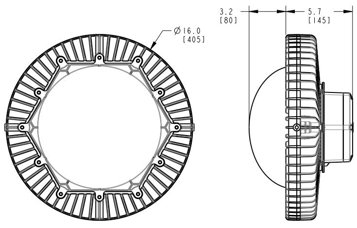

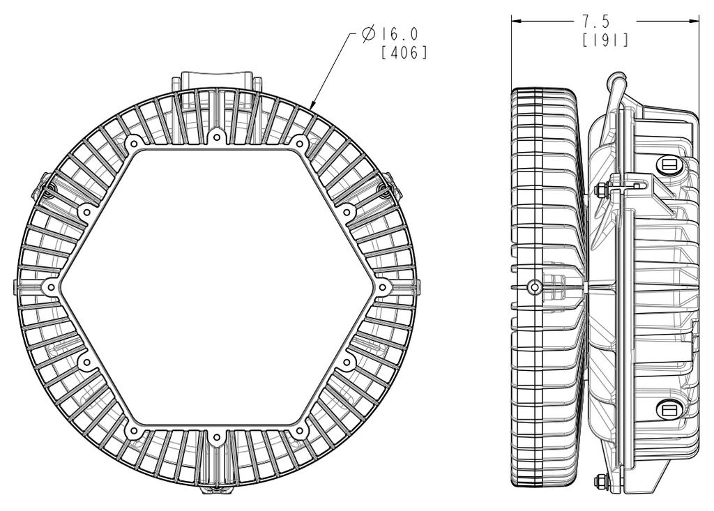
5 Technical Diagrams Dimensions in inches [mm]


6 Official Statement All statements, technical information, and recommendations contained herein are based on information and tests that Dialight believes to be reliable. The accuracy or completeness thereof is not guaranteed. In accordance with Dialight Terms and Conditions of Sale and since conditions of use are outside our control, the purchaser should determine the suitability of the product for his or her intended use and assumes all risk and liability whatsoever in connection therewith.
Operation/Installation Instructions
 Important Information These instructions contain safety information, read and follow them carefully. Dialight will not accept any responsibility for injury, damage or loss which may occur due to incorrect
Operating Instructions
 Important Information: These instructions contain safety information, read and follow them carefully. Dialight will not accept any responsibility for injury, damage or loss which may occur due to incorrect
MODELS. 2 & 4 Low Profile Linears
 INSTALLATION AND MAINTENANCE MANUAL SAFESITE LED LINEAR FIXTURE Document No: 9100-127-2182-99 Rev D December, 2016 MODELS 2 & 4 Low Profile Linears These instructions contain important safety information,
MODELS SafeSite LED Linear, Class I Div V, 2 & 4 Versions
 INSTALLATION AND MAINTENANCE MANUAL SAFESITE LED LINEAR FIXTURE Document No: 9100-127-1622-00 Rev E December, 2016 MODELS SafeSite LED Linear, Class I Div. 1 347-480V, 2 & 4 Versions All the above Models
MODELS 2 & 4 Top Conduit Linears
 INSTALLATION AND MAINTENANCE MANUAL SAFESITE AND DUROSITE LED LINEAR FIXTURE Document No: 9100-127-1885-99 Rev E December, 2016 MODELS 2 & 4 Top Conduit Linears These instructions contain important safety
SAVE THESE INSTRUCTIONS!!
 IMPORTANT: Please read carefully before installation and retain for future reference To prevent possible shock hazard, the fixture should be installed by a qualified licensed electrician All electrical
Operating Instructions
 DuroSite & SafeSite Area Light with Adapters Important Information: These instructions contain safety information, read and follow them carefully. Dialight will not accept any responsibility for injury,
Operating Instructions
 Important Information: These instructions contain safety information, read and follow them carefully. Dialight will not accept any responsibility for injury, damage or loss which may occur due to incorrect
FOR USE WITH MODEL NUMBERS:
 INSTALLATION AND MAINTENANCE MANUAL SAFESITE /DUROSITE HZx/ STW SERIES WITH MOUNTING ACCESSORIES Document No: 9100-127-2297-99 Rev C AUGUST 2015 FOR USE WITH MODEL NUMBERS: HZXXXXXW01 HZXXXXXW45 HZXXXXXS45
High Bay Luminaire Series
 High Bay Luminaire Series INSTALLATION INSTRUCTIONS The High Bay Luminaire is ideal for installations with mounting heights over 25 feet. The fixture can be mounted with a hook or pendant with flexible
HBDBM High Bay Series
 HBDBM High Bay Series INSTALLATION INSTRUCTIONS The High Bay Luminaire is ideal for installations with mounting heights over 25 feet. The fixture can be mounted with a hook or pendant with flexible adjustments
SAVE THESE INSTRUCTIONS FOR FUTURE REFERENCE IMPORTANT SAFEGUARDS READ AND FOLLOW ALL SAFETY INSTRUCTIONS
 Champ Fluorescent Luminaires DMVFB Auxiliary Series - 52, 64, & 84 Watt Installation & Maintenance Information SAVE THESE INSTRUCTIONS FOR FUTURE REFERENCE IF 1713 IMPORTANT SAFEGUARDS READ AND FOLLOW
SynergEX Panelboards for Hazardous Locations
 SynergEX Panelboards for Hazardous Locations Installation & Maintenance Information 1. APPLICATION SynergEX panelboards provide short circuit protection for feeder or branch circuits to control lighting,
SURFACE/CEILING & SUSPENDED MOUNT INSTALLATION
 SURFE/CEILING & SUSPENDED MOUNT INSTALLATION E477827 E477827 APPLICATION NL luminaires are designed for use indoors, outdoors, wet locations, areas containing moisture, dirt, corrosion, vibration and rough
INSTALLATION INSTRUCTION MANUAL
 INSTALLATION INSTRUCTION MANUAL LED FLOOD LIGHT, 100-277VAC MODELS: SL923FLF-15W; SL923FLF-30W; SL923FLF-50W; SL923FLF-80W; SL923FLF-100W; SL923FLF-150W; SL923FLF-300W Model number parameter list: Model
Input Voltage: AC: VAC HC: VAC (50/60Hz) Electrical Ratings: WIDE FROSTED MODEL
 Electrical Ratings: WIDE FROSTED MODEL") WLL MOUNT INSTLLTION E477827 E477829 PPLICTION RS luminaires are designed for use in hazardous locations, indoors, outdoors, wet location, and areas containing moisture, dirt, corrosion, vibration, and
WLL MOUNT INSTLLTION E477827 E477829 PPLICTION RS luminaires are designed for use in hazardous locations, indoors, outdoors, wet location, and areas containing moisture, dirt, corrosion, vibration, and
R. STAHL Schaltgeräte GmbH Geschäftsbereich Leuchten Nordstraße Weimar, Germany
 , INC. ECOLUX 6600 Series 6600/5 Explosion Protected Fluorescent Light Fixtures for Hazardous and Corrosive Applications Please read this entire document before beginning any work. 1. Safety Instructions
HAZARDOUS LOCATION STREET LIGHT SLA SERIES INSTALLATION INSTRUCTIONS
 Single Module Series Double Module Series Triple Module Series IMPORTANT: Please read carefully before installation and retain for future reference To prevent possible shock hazard, the fixture should
LED Area Light. This is the fixture of choice for all of our dealerships. Contact Us:
 LED Area Light This is the fixture of choice for all of our dealerships. Contact Us: 7057 Marcelle St, Paramount, CA 90723 800-640-0386 www.altechefficiency.com sales@altechefficiency.com Specifications
LED IMPORTANT SAFETY INSTRUCTIONS
 LED IMPORTANT SAFETY INSTRUCTIONS READ AND FOLLOW ALL SAFETY INSTRUCTIONS! SAVE THESE INSTRUCTIONS AND DELIVER TO OWNER AFTER INSTALLATION To reduce the risk of death, personal injury or property damage
LED Area Light. scratch that. This is the fixture of choice for all of our dealerships. Contact Us:
 LED Area Light scratch that. This is the fixture of choice for all of our dealerships. Contact Us: 7057 Marcelle St, Paramount, CA 90723 800-640-0386 www.altechelectronics.com sales@altechelectronics.com
INSPECTOR LINE LOAD SIMULATOR INSTRUCTION MANUAL TASCO, INC.
 INSPECTOR LINE LOAD SIMULATOR INSTRUCTION MANUAL INS120P TASCO, INC. THIS TESTER IS DESIGNED FOR USE ONLY BY QUALIFIED ELECTRICIANS. IMPORTANT SAFETY WARNINGS mwarning Read and understand this material
RU SERIES UPGRADE TempAssure Compatible
 RU SERIES UPGRADE TempAssure Compatible This converter section has been designed as a converter section replacement in the following MagneTek or Parallax Power Supply series products and models with DC
LED AC DRIVERLESS FLOODLIGHTS WITH PIR FOR MODEL: FLAC10BPIR, FLAC20BPIR, FLAC30BPIR & FLAC50BPIR
 INTRODUCTION The LED AC Driverless Floodlights with PIR include a hanging / mounting bracket and a 100cm cable. SPECIFICATION LED 800-4000lm IP65 180-240V IK07 6000K 50Hz >80 Ra 10W- 50W Dimensions: FLAC10BPIR:
Schaltgeräte GmbH GmbH Geschäftsbereich Leuchten
 ,, INC. INC. GmbH 9001 Knight Road Houston, TX 77054 Tel: 800-782-4357 FAX: 713-792-9301 E-mail: sales@rstahl.com Website: www.rstahl.com & SHEET EXLUX 6000 Series 6000/5 6000/8 Explosion Protected Fluorescent
READ AND FOLLOW ALL SAFETY INSTRUCTIONS! SAVE THESE INSTRUCTIONS AND DELIVER TO OWNER AFTER INSTALLATION
 READ AND FOLLOW ALL SAFETY INSTRUCTIONS! SAVE THESE INSTRUCTIONS AND DELIVER TO OWNER AFTER INSTALLATION To reduce the risk of death, personal injury or property damage from fire, electric shock, falling
INSTALLATION INSTRUCTION MANUAL
 INSTALLATION INSTRUCTION MANUAL LED FLOOD LIGHT, 100-277VAC Rev A Aug 2015 SERIES: 71531,71532,71533,71541,71542,71543,71544,71545,71551,71552,71553,71554, 71555, 71556, 71557, 71561, 71562, 71563, 71564,
HPNLS-HO. Installation Manual
 Installation Manual WARNING: Do not lift fixture by cables. This could result in permanent damage to both the fixture and the cables. Damage resulting from grasping cables and/or putting undue pressure
Installation Guide. WARNINGS Read all instructions and warnings before attempting installation
 Installation Guide WARNINGS Read all instructions and warnings before attempting installation ALWAYS MAKE ABSOLUTELY SURE THE POWER IS OFF WHEN PERFORMING THE FIXTURE MODIFICATION. DURING INSTALLATION,
Installation and Maintenance Manual (2014)
") TRULY GREEN SOLUTIONS 100~200W Modular LED Light Fixture Installation and Maintenance Manual (2014) 1/10 Content Warning A. Hanging Ring Mount B. Pendant Mount C. Surface Mount D. Universal Hanging Bracket
TRULY GREEN SOLUTIONS 100~200W Modular LED Light Fixture Installation and Maintenance Manual (2014) 1/10 Content Warning A. Hanging Ring Mount B. Pendant Mount C. Surface Mount D. Universal Hanging Bracket
HBDB High Bay Fixture with Occupancy Sensor
 HBDB High Bay Fixture with Occupancy Sensor INSTALLATION INSTRUCTIONS The High Bay Luminaire is ideal for installations with mounting heights over 20 feet. The fixture can be mounted with a hook or pendant
Installation and Operation Instructions 10/04/13
 ELI-S-100 With DIMMING CAPABILITIES Installation and Operation Instructions eli series emergency lighting inverters NRTL/C! IMPORTANT SAFEGUARDS! WHEN USING ELECTRICAL EQUIPMENT, BASIC SAFETY PRECAUTIONS
Installation Instructions
 SPECIFICATIONS v2 Fixture Mount Power Pack Model: Fixture Sensor Power Pack V2 120/277/347VAC, 60Hz @347VAC 3.4A () 2A () Power...120/277/347VAC, 60Hz Relay Type... Form C with Zero Crossing on N.O. only
60 Watt Industrial LED Low Bay Light
 60 Watt Industrial LED Low Bay Light Owner s Manual WARNING: Read carefully and understand all ASSEMBLY AND OPERATION INSTRUCTIONS before operating. Failure to follow the safety rules and other basic safety
ArenaVision LED BVP420/BVP978
 ArenaVision LED BVP420/BVP978 Lb 65.5 max Class I 27.83 inch 24.21 inch 17.56 inch 30.91 inch Dimensions in inches Any modification on the luminaire will cancel the warranty Tolerances on light flux: +/-
LED IMPORTANT SAFETY INSTRUCTIONS
 LED IMPORTANT SAFETY INSTRUCTIONS READ AND FOLLOW ALL SAFETY INSTRUCTIONS! SAVE THESE INSTRUCTIONS AND DELIVER TO OWNER AFTER INSTALLATION To reduce the risk of death, personal injury or property damage
LED UFO High Bay with j-box Installation Instruction
 Our new UFO style is the latest in LED technology. Smaller, longer lasting and more efficient. Less than 1 inches in diameter, the new design is more compact without sacrificing performance. The UHB series
R. STAHL Schaltgeräte GmbH Geschäftsbereich Leuchten Nordstraße Weimar, Germany
 ECOLUX 6608 Series 6608/5 Explosion Protected Fluorescent Emergency Light Fixtures for Hazardous and Corrosive Applications Please read this entire document before beginning any work. 1. Safety Instructions
Installation Instructions: Eco Linear High Bay
 Installation Instructions: Eco Linear High Bay Installation Notes & Precautions: Read all precautions, warnings, instructions contained in this document. These instructions can be used to install Eco Linear
General Installation Instructions LED
 General Installation Instructions LED To reduce the risk of death, personal injury or property damage from fire, electric shock, falling parts, cuts/abrasions and other hazards, please read all warnings
SAVE THESE INSTRUCTIONS
 READ AND FOLLOW ALL SAFETY INSTRUCTIONS! SAVE THESE INSTRUCTIONS AND DELIVER TO OWNER AFTER INSTALLATION IMPORTANT SAFEGUARDS When using electrical equipment, basic safety precautions should always be
Albeo TM LED Luminaire Heavy Industrial High Bay Lighting (ABR1-Series)
") GE Lighting Installation Guide Albeo TM LED Luminaire Heavy Industrial High Bay Lighting (ABR1-Series) Features UL 1598 Suitable for Wet Locations IP66 Rated Ingress Protection BEFORE YOU BEGIN Read these
GE Lighting Installation Guide Albeo TM LED Luminaire Heavy Industrial High Bay Lighting (ABR1-Series) Features UL 1598 Suitable for Wet Locations IP66 Rated Ingress Protection BEFORE YOU BEGIN Read these
FL15 FL50 FL100 USER MANUAL USER MANUAL FL15 PRODUCT OVERVIEW HARDWARE AND SET-UP. page 1
 PRODUCT OVERVIEW The FL15, FL50 and FL100 are LED luminaries designed for use with fiber optics for illumination purposes. This FiberLamp line can be used with both end-emitting and side-emitting fiber
LED Recessed Troffer Retrofit Kit
 Model # TRK series LED Recessed Troffer Retrofit Kit Installation Instructions PACKAGE CONTENTS A B E Part Item Name Qty. A Retrofit assembly 1 B Bracket 2 C Sheet metal screw 4 D Wire nuts 5 E Gap channel
General Installation Instructions LED
 General Installation Instructions LED To reduce the risk of death, personal injury or property damage from fire, electric shock, falling parts, cuts/abrasions and other hazards, please read all warnings
INSTRUCTIONS FOR THE RELIANCE Fast/Tran TM ARL0909 & ARL0909R
 INSTRUCTIONS FOR THE RELIANCE Fast/Tran TM ARL0909 & ARL0909R THE RELIANCE Fast/Tran IS NOT FOR "DO-IT-YOURSELF" INSTALLATION. It must be installed by a qualified electrician thoroughly familiar with all
ComfortPoint Programmable Lon, VAV/Unitary Controllers
 ComfortPoint Programmable Lon, VAV/Unitary Controllers Controller Model Programmable Type Universal Inputs (UI) Table 1. Controller configurations. Digital Inputs (DI) PRODUCT DESCRIPTION INSTALLATION
CFP-LED Contractor Select Flat Panel. Installation Instructions
 IMPORTANT SAFETY INSTRUCTIONS To reduce the risk of death, personal injury or property damage from fire, electric shock, falling parts, cuts/abrasions, and other hazards please read all warnings and instructions
ecolor Burst Powercore Architectural and landscape LED spotlight with solid color light
 Architectural and landscape LED spotlight with solid color light Architectural and landscape LED spotlight with solid color light is a high-output, exterior-rated LED lighting luminaire designed for accent
PIL0478 ISSUE 01/ 07/16
 ISSUE 01/ 07/16 PIL0478 ZAFIR G9 CEILING FITTING PIL0478 ISSUE 01/ 07/16 PART C PART E PART 21 SELV 1 1.B 1 3.1 3.3 3.4 3.5 3.6, 3.8 3.10 3.12 3.14 3.16 3.17 3.18 3.19 3.19 ATTENTION! THE TABLE BELOW
Asymmetrical Installation Instructions. Components: i2cove Asymmetrical LED Light Fixtures. 12 [305mm] [918mm] 48.
![Asymmetrical Installation Instructions. Components: i2cove Asymmetrical LED Light Fixtures. 12 [305mm] [918mm] 48.](/thumbs/77/74625192.jpg "Asymmetrical Installation Instructions. Components: i2cove Asymmetrical LED Light Fixtures. 12 [305mm] [918mm] 48.") support@i2systems.com www.i2systems.com Electrical Specifications PARAMETER Input Power VALUE 8 Watts* / Ft Input Voltage 120-277V AC, 50/60 Hz Max. Fixture Run Length LED Color (CCT) 8 Watts: 120VAC:
support@i2systems.com www.i2systems.com Electrical Specifications PARAMETER Input Power VALUE 8 Watts* / Ft Input Voltage 120-277V AC, 50/60 Hz Max. Fixture Run Length LED Color (CCT) 8 Watts: 120VAC:
CIVACON GROUND VERIFICATION RACK MONITOR SYSTEM and ASSOCIATED EQUIPMENT
 GROUND VERIFICATION RACK MONITOR SYSTEM and ASSOCIATED EQUIPMENT INSTALLATION AND WIRING INSTRUCTIONS MANUAL 8030 MANUAL PART NUMBER JANUARY 2011. 4304 MATTOX RD. KANSAS CITY, MO 64150 TABLE OF CONTENTS
Installation Instructions: Memory-Dimmable SEP T8 Tube Lamps
 Installation Instructions: Memory-Dimmable SEP T8 Tube Lamps Installation Notes & Precautions: Memory-Dimmable SEP T8 LED Tube Lamp Read all precautions, warnings, instructions contained in this document.
Assembly instruction. Pendant Light Toccata GENERAL REMARKS ON SAFETY: Technical data: BOM
 GENERAL REMARKS ON SAFETY: Read all of these instructions before installing fixtures. Keep all of the instructions for future reference. Turn off power before installing fixture. Installation is to be
MaxLite LED Medium Area Light
 General Safety Information To reduce the risk of death, personal injury or property damage from fire, electric shock, falling parts, cuts/abrasions, and other hazards read all warnings and instructions
Installation Instruction ALG Series LED Area Light Version: 3.1
 IMPORTANT SAFETY INSTRUCTIONS READ CAREFULLY BEFORE INSTALLING THE FIXTURE. RETAIN THESE INSTRUCTIONS FOR FUTURE REFERENCE. To reduce the risk of death, personal injury or property damage from fire, electric
LED Garage Light INSTALLATION INSTRUCTIONS. *Model number noted on carton label
 LED Garage Light *Model number noted on carton label INSTALLATION INSTRUCTIONS Model Number / Número de Modelo / Numéro des modèle SGLL 24 PIR (24 LED Garage Light) Actual Dimensions 10 W x 3-1/2 H x 24-1/2
ANZI Transfer Switch and Generator Wiring Installation Addendum
 ANZI Transfer Switch and Generator Wiring Installation Addendum Reference all appropriate documentation. NOT INTENDED FOR USE IN CRITICAL LIFE SUPPORT APPLICATIONS. THIS PRODUCT CAN BE INSTALLED BY THE
Vol-Con XL (61-086) Voltage/Continuity Tester and Vol-Test (61-085) Voltage Tester Instruction Manual WARNING
 Voltage/Continuity Tester and Vol-Test (61-085) Voltage Tester Instruction Manual WARNING") Vol-Con XL (61-086) Voltage/Continuity Tester and Vol-Test (61-085) Voltage Tester Instruction Manual WARNING #61-085 #61-086 Read First: Safety Information This tester complies with UL3111-1, Cat III-600
Vol-Con XL (61-086) Voltage/Continuity Tester and Vol-Test (61-085) Voltage Tester Instruction Manual WARNING #61-085 #61-086 Read First: Safety Information This tester complies with UL3111-1, Cat III-600
GE Lighting. Heavy Industrial High Bay & Low Bay Lighting. (ABR1 - Series) imagination at work
 imagination at work") GE Lighting Albeo LED Luminaire Heavy Industrial High Bay & Low Bay Lighting (ABR1 - Series) imagination at work Product Features The Albeo ABR1-Series is an IP66 rated fixture for demanding industrial
GE Lighting Albeo LED Luminaire Heavy Industrial High Bay & Low Bay Lighting (ABR1 - Series) imagination at work Product Features The Albeo ABR1-Series is an IP66 rated fixture for demanding industrial
INSTALLATION NOTES: nbeckon-26
 INSTALLATION NOTES: nbeckon-26 1. Caution and Safety Instructions Qualified personnel must install and/or service product in a manner consistent with its intended use and in compliance with the National
Visor Compact Architectural LED Wallpack. Technical Specifications VISOR TM. Visor Configuration Information. Project Catalog Number Type Date
 VISOR TM led wallpack Visor compact architectural LED wallpacks replace up to 250W pulse start metal halide wall-mounted fixtures in perimeter, security, and entrance way applications while consuming up
MaxLite LED UTILITY WRAP FIXTURES
 General Safety Information To reduce the risk of death, personal injury or property damage from fire, electric shock, falling parts, cuts/abrasions, and other hazards read all warnings and instructions
INSTALLATION INSTRUCTIONS LIGHTPLANE 3.5. LP3.5 Suspended LED. A nd Avenue, Unit 1. CA P E W alwusa.
 Oakland, INSTALLATION INSTRUCTIONS LIGHTPLANE 3.5 LP3.5 Suspended LED A 1035 22nd Avenue, Unit 1 n CA 94606 P 510.489.2530 E TalkToUs@alwusa.com W alwusa.com Safety & Warnings! 1. Read all instructions.
AC CONVERTER / BATTERY CHARGER
 AC CONVERTER / BATTERY CHARGER User s Manual MODEL #: CON120AC12/24VDC Listed to UL 458 and CSA 22.2 NO. 107.1 Standards Contents INTRODUCTION... 3 Important Safety Instructions... 3 1. General Description...
diode led 24VDC MAGNETIC DIMMABLE DRIVER SPECIFICATION SHEET 24VDC OVERVIEW FEATURES
 diode led a division of elemental LED 24VDC MAGNETIC DIMMABLE DRIVER 24VDC WET LOCATION DIMMABLE SPECIFICATION SHEET OVERVIEW 24VDC Magnetic Dimmable Drivers are perfect for supplying low voltage power
USER MANUAL. 200A AC Mini Clamp Meter. Model MA130. Please visit for user manual translations
 USER MANUAL 200A AC Mini Clamp Meter Model MA130 Please visit www.extech.com for user manual translations Introduction Thank you for selecting the Extech Instruments 200A AC Mini Clamp Meter. The MA130
Nature Power Inverters. True Sinewave Inverter Modified Sinewave Inverter. Owner s Manual
 Version 1.1 Version 2 Nature Power Inverters True Sinewave Inverter Modified Sinewave Inverter Owner s Manual!!!!!!!!!!! 38304 38204 For safe and optimum performance, the Power Inverter must be used properly.
INSTRUCTION SHEET PRL-97X04 AC AND DC VOLTAGES
 INSTRUCTION SHEET PRL-97X04 AC AND DC VOLTAGES Page 1 of 18 The PRL LED Point Rollover Light is used for heliport TLOF and FATO applications where an inset light is required. The thick soda lime glass
ACE Variable Frequency Drive System
 ACE Variable Frequency Drive System Installation & Maintenance Information SAVE THESE INSTRUCTIONS FOR FUTURE REFERENCE IF 1690 BLOWER COOLING INTAKE SHROUDS BLOWER FUSE BLOCK TEMPERATURE CONTROLLER TRANSFORMER
WASHDOWN SERIES 2 LED MODULES v 1.0 FIXTURE SPECIFICATION SHEET TYPE
 WASHDOWN SERIES 2 LED MODULES v 1.0 FIXTURE SPECIFICATION SHEET TYPE WASHDOWN 2M ABOUT THE LUSIO WASHDOWN SERIES The Lusio Commercial and Industrial Washdown Series features LED high bay fixtures for use
Installing Power Components
 This chapter provides instructions on how to install and reinstall power components in the Cisco NCS 4016 chassis. It also covers connecting and disconnecting power and powering on the chassis. The Cisco
Installation Instructions Central Battery Units
 Phone: 605.542.4444 concealite.com! Installation Instructions s Please Save These Instructions Important Safeguards Read and Follow All Safety Instructions When using electrical equipment, basic safety
Spun Bay Installation Standard Version (non dimmable), Hook Mount
, Hook Mount") Spun Bay Installation Standard Version (non dimmable), Hook Mount WARNING: Make sure that all power is turned off while installing fixture. Do not turn power on until fixture is completely installed. Turn
Spun Bay Installation Standard Version (non dimmable), Hook Mount WARNING: Make sure that all power is turned off while installing fixture. Do not turn power on until fixture is completely installed. Turn
LED IMPORTANT SAFETY INSTRUCTIONS
 READ AND FOLLOW ALL SAFETY INSTRUCTIONS! SAVE THESE INSTRUCTIONS AND DELIVER TO OWNER AFTER INSTALLATION To reduce the risk of death, personal injury or property damage from fire, electric shock, falling
Models beginning with MO, MK, 7B, 6S, 6F or 5B. Product Description. Technical Specifications. Installation Instructions.
 Models beginning with MO, MK, 7B, 6S, 6F or 5B The Mini Meter Product Description Technical Specifications Installation Instructions February 28 th, 2013 1. Product Description...2 1.1 General Description...2
Power Inverter 400 MW Owner s Manual
 Power Inverter 400 MW 1204 Owner s Manual For safe and optimum performance, the Power Inverter must be used properly. Carefully read and follow all instructions and guidelines in this manual and give special
Installation Manual. Rev
 Installation Manual ChargePro 620 Charging Station is a trademark of SemaConnect, Inc. All other products or services mentioned are the trademarks, service marks, registered trademarks or registered service
Installing and Removing Power Supplies
 Power Supply Overview, page 2 Installing Power Supplies, page 3 Removing Power Supplies, page 8 Finding the Serial Number, page 9 1 Power Supply Overview Power Supply Overview You can install two types
Installation Instructions for Appleton Mercmaster LED Luminaire
 650559-000 INSTRUCTION SHEET Installation Instructions for Appleton Mercmaster LED Luminaire FOR PROPER AND SAFE INSTALLATION OF THIS PRODUCT, PLEASE READ THE FOLLOWING INSTRUCTIONS. Product Safety Signal
Sentry Battery Charger. Installation and Operations Manual Section 75
 Sentry Battery Charger Installation and Operations Manual 00-02-0616 03-03-08 Section 75 In order to consistently bring you the highest quality, full featured products, we reserve the right to change our
LAL SERIES LED LUMINAIRE
 INSTALLATION, OPERATION & MAINTENANCE DATA SHEET LAL SERIES LED LUMINAIRE CAUTION: LAL SERIES LED LUMINAIRE Before installing, make sure you are compliant with area classifications, failure to do so may
LED IMPORTANT SAFETY INSTRUCTIONS
 READ AND FOLLOW ALL SAFETY INSTRUCTIONS! SAVE THESE INSTRUCTIONS AND DELIVER TO OWNER AFTER INSTALLATION To reduce the risk of death, personal injury or property damage from fire, electric shock, falling
Mass Sine 24/10000 Mass Sine 24/15000
 USERS- AND INSTALLATION MANUAL Mass Sine 24/10000 Mass Sine 24/15000 Modular high power inverter system MASTERVOLT Snijdersbergweg 93, 1105 AN Amsterdam The Netherlands ENGLISH: PAGE 1 Tel.: +31-20-342
IMPORTANT SAFEGUARDS
 INSTRUCTION MANUAL NON-INTERRUPTIBLE AC INVERTER SYSTEM MODEL EAC FTM 350 FOR EMERGENCY LIGHTING POWER IMPORTANT SAFEGUARDS When using electrical equipment, basic safety precautions should always be followed,
INSTALLATION INSTRUCTIONS MOONRING 1 LP1/MR1
 INSTALLATION INSTRUCTIONS MOONRING 1 LP1/MR1 Suspended, Ceiling LED n A 1035 22nd Avenue, Unit 1 Oakland, CA 94606 P 510.489.2530 E TalkToUs@alwusa.com W alwusa.com Safety & Warnings! 1. Read all instructions.
The installation must only be performed by a licensed electrician. Disconnect power before installing the product or servicing it.
 WARNING l The installation must only be performed by a licensed electrician. l To prevent death, injury or damage to property, this product must be installed in accordance to National Electrical Code (NFPA70)
IMPORTANT SAFETY INSTRUCTIONS READ AND FOLLOW ALL INSTRUCTIONS SAVE THESE INSTRUCTIONS
 1 AQUALUMIN III NICHELESS POOL LIGHT INSTALLATION GUIDE IMPORTANT SAFETY INSTRUCTIONS READ AND FOLLOW ALL INSTRUCTIONS SAVE THESE INSTRUCTIONS Section Contents 1. Installing a mounting bracket and light
Flameproof Level Sensor (Flameproof F/S FP)
") The Deeter F/S FP is magnetic float on a reed switch or Hall Effect sensor stem for control and indication of a liquid level while in a potentially explosive atmosphere. II 1/2G 2D Ex d IIC (*) Ga/Gb Ex
The Deeter F/S FP is magnetic float on a reed switch or Hall Effect sensor stem for control and indication of a liquid level while in a potentially explosive atmosphere. II 1/2G 2D Ex d IIC (*) Ga/Gb Ex
MaxLite StaxMax LED Flood Lights
 Operating Instructions MaxLite StaxMax LED Flood Lights Input Rating 120V-277V 50/60Hz (347/480v optional) Wet Location Rated IP65 Operating temperature -22⁰F to 105⁰F General Safety Information 1. READ
Jandy Pro Series WaterColors LED Lights Underwater Large and Small Light
 installation Manual English Jandy Pro Series WaterColors LED Lights Underwater Large and Small Light FOR YOUR SAFETY - This product must be installed and serviced by a contractor who is licensed and qualified
INSTRUCTIONS FOR THE RELIANCE CONTROLS ARM SERIES AUTOMATIC TRANSFER SWITCH
 INSTRUCTIONS FOR THE RELIANCE CONTROLS ARM SERIES AUTOMATIC TRANSFER SWITCH THE RELIANCE CONTROLS ARM SERIES AUTOMATIC TRANSFER SWITCH IS NOT FOR "DO-IT-YOURSELF" INSTALLATION. It must be installed by
C.fm Page 1 Thursday, February 21, :28 AM Raptor user manual
 Raptor user manual 1 mounting bracket 2 swivel lock 3 clamp hole 4 lamp access screws 5 air vents 6 AC input & main fuse 7 cooling fan Thank you for selecting the Martin Raptor. This Martin lighting fixture
HPFB. Installation Manual WARNING: DO NOT LIFT FIXTURE BY CABLES.
 Installation Manual WARNING: DO NOT LIFT FIXTURE BY CABLES. This could result in permanent damage to both the fixture and the cables. Damage resulting from grasping cables and/ or putting undue pressure
PD404-AN V analog control 4 Channel x 500 W Dimmer & Switch Packs ANALOG 0-10 V. Serial Number
 0-10V analog control 4 Channel x 500 W Dimmer & Switch Packs ANALOG 0-10 V 4 circuit Analog 1-10V 4 x 4 A. Dimmer pack Serial Number Dimmers Indicators Digital Lighting Systems,Inc Info@digitallighting.com
LED IMPORTANT SAFETY INSTRUCTIONS
 LED IMPORTANT SAFETY INSTRUCTIONS READ AND FOLLOW ALL SAFETY INSTRUCTIONS! SAVE THESE INSTRUCTIONS AND DELIVER TO OWNER AFTER INSTALLATION To reduce the risk of death, personal injury or property damage
Model LA 4300 Time Delay OFF Controller
 ISIMET LA Series Model LA 4300 Time Delay OFF Controller Installation, Operation and Maintenance Manual Application: The Time Delay OFF Controller operates as a single output controller where the application
EdgeLED TM Range. Installation and Operating Instructions EdgeLED TM RANGE INSTALLATION NON-EMERGENCY LUMINAIRES PRE INSTALLATION
 EdgeLED TM Range THIS FITTING SHOULD NOT BE USED IN AREAS EXCEEDING 25 C AMBIENT AIR TEMPERATURE This fitting must be installed by a qualified electrician and wired in accordance with the latest edition
Pneumatic Isolation Module
 Pneumatic Isolation Module (Cat. 2030-Pxxxxx) ATTENTION: Hazardous Voltage or other forms of energy could be present. To avoid serious injury or death: Prior to beginning the installation and wiring process,
User Manual JS-ICON. 624 ARCH Dimmer Rack. JOHNSON SYSTEMS INC. Spring
 User Manual JS-ICON 624 ARCH Dimmer Rack JOHNSON SYSTEMS INC. Spring 2007 2002161 Table of Contents JS-ICON 624 DMX JS-ICON 624 CC 6-2.4kW Dimming Strip JS-ICON 624 ND 6-2.4kW Relay Strip Introduction...3