The speaker soundbox improves the performance of the speaker in locos which have no purpose designed speaker cradle.
|
|
|
- Stephen Parker
- 5 years ago
- Views:
Transcription

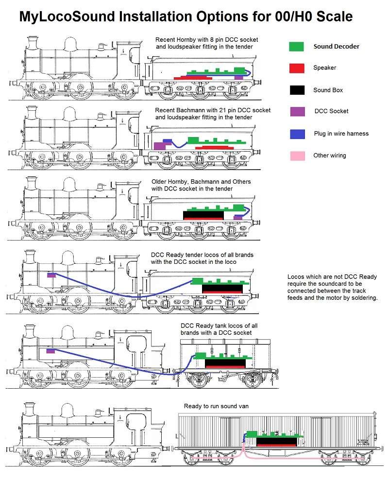
1 1 1.OVERVIEW 8 pin DCC sound decoder with adjustable back-emf loco control. Fully adjustable sounds to match the chuff and whistle to the prototype loco. Provides a chuff which matches the loco speed and load Long and short, plain and chime whistles with adjustable tone. Function key operation of the whistle, optional bell, safety valve and guards whistle. For 00, H0 and 0 scale locos or can be used in a sound van or as a fixed sound unit on N scale layouts. Supports simple and extended addresses and consists. Adjustable acceleration, deceleration and speed curve. 2. CONTENTS Each MyLocoSound sound decoder contains three components. The decoder generates synthesised sound which is adjustable to reproduce the sounds of most steam locos. It is designed to fit in the tenders of 00/H0 locos or in trailing goods vans. A stay-alive capacitor is fitted to the soundcard to improve sound continuity over dirty track, insulfrog points, etc. The main wiring harness connects the soundcard to the 27mm, 8Ω speaker and to an 8 pin DCC plug. Locos without a DCC socket can be connected by soldering. The speaker soundbox improves the performance of the speaker in locos which have no purpose designed speaker cradle. The last page of these instructions shows, diagrammatically, the different ways in which the decoder can be installed. 3. SPEAKERS AND SOUND QUALITY Your sound kit includes a speaker which has been selected for its small size which simplifies installations in the confined space of small scale locos and tenders. The cost of this small size is a reduced bass performance. If space is not a problem then you can replace the supplied speaker with a high bass, 4 or 8 ohm speaker purchased from your local model shop. An 8ohm speaker is ideal. If a 4 ohm speaker is used then the volume should be kept below 70% of maximum. If a 4 ohm speaker is used above this level then the decoder may automatically shut off sound for a time if it is overheating. No damage will occur, it is just a precaution which applies only to 4 ohm speakers.


2 2 4. INSTALLING IN A HORNBY OR BACHMANN LOCO WITH A TENDER FITTED FOR DCC SOUND Recent Hornby and Bachmann tender locos are designed for DCC sound. They have a decoder socket in the tender and also a downward pointing speaker fitting. The MyLocoSound sound decoder is designed to be installed in these with no soldering and minimal, if any, modification. Just follow these steps: 1. Remove the tender body from the tender chassis by following the manufacturer s instructions. 2. Measure the internal width of the tender body. If the width is less than 27mm then you will need to use the installation method described in section 63 of these instructions. 3. Install the speaker in the tender floor by following the manufacturer s instructions and taking care not to break the connections to the brown wires. The speaker fitting in the tender floor is designed to accept the speaker alone and not the soundbox which improves the sound quality. In the absence of the soundbox, we recommend that you take a piece of card or felt, around 0.3mm thick, and cut it to the dimensions shown alongside. The diagram is full size and can be used as a template. Then place it between the back of the speaker and the frame which holds the speaker down, so that it is clamped in place. This will improve the quality of the sound. 4. Take the main MyLocoSound wiring harness and plug the white nine pin connector into the soundcard. Make sure that it is fully pushed home. 5. Remove the DCC blanking plug from the DCC socket in the tender by pulling it vertically upwards. If the tender has an 8 pin DCC socket then plug the 8 pin plug at one end of the wireless harness directly in to it. Ensure that pin 1 of the plug (the orange wire) is inserted into pin 1 of the socket (which should be marked). If the tender has a 21 pin DCC socket then you will need to use a 21 to 8 pin adaptor which your local model shop will be able to supply. 6. Before reassembling the tender, we suggest that you put the loco and tender onto the track to check that the sound is working. Refer to section 10 for operating instructions. 7. Finally, reassemble the tender. Note that in Hornby tenders, the cut outs in the soundcard match the locating pillars and so the soundcard will go only one way around. In the Hornby loco in the above photo, the soundcard has been fixed in place, with the wiring harness underneath, using double sided tape. In locos with very low tenders, you may have to raise the coal load to make sufficient space inside for the soundcard. 5. INSTALLING IN OTHER DCC READY TENDER LOCOS Most 00 and HO scale locos introduced in the past decade are DCC ready. That means that they have a decoder socket either in the tender or in the loco. The MyLocoSound sound decoder is designed to be installed in these with no soldering and minimal, if any, modification. Just follow these steps: 1. Remove the tender body from the tender chassis by following the manufacturer s instructions. 2. Measure the internal width of the tender body. If the width is less than 27mm then you will need to use the installation method described in section 6 of these instructions.

3 3 3. Press fit the MyLocoSound speaker into its soundbox taking care not to damage the speaker diaphragm. The two wires will pass through the longer pair of slots. Then glue the speaker, face upwards, onto the tender floor using a contact adhesive or bluetack. 4. Take the main MyLocoSound wiring harness and plug the white nine pin connector into the soundcard. Make sure that it is fully pushed home. 5. The next step depends on the location of the DCC socket. If it is in the loco then remove the loco body by following the manufacturer s instructions. You will need to run the main wiring harness forward from the soundcard, which will be installed into the tender, through the rear underside of the loco to the DCC socket. The loco and tender will then become permanently attached. Note that the blue, yellow and white wires are not required at all with DC locos and can be removed. 6. Remove the DCC blanking plug from the DCC socket in the tender by pulling it vertically upwards. If the tender has an 8 pin DCC socket then plug the 8 pin plug at one end of the wireless harness directly in to it. Ensure that pin 1 of the plug (the orange wire) is inserted into pin 1 of the socket (which should be marked). If the tender has a 21 pin DCC socket then you will need to use a 21 to 8 pin adaptor which your local model shop will be able to supply. 7. Before reassembling the loco and tender, we suggest that you put them onto the track to check that the sound is working. Refer to section 10 for operating instructions. 8. If the DCC socket is in the loco then re-assemble the loco now. 9. Finally, reassemble the tender. In locos with very low tenders, you may have to raise the coal load to make sufficient space inside for the soundcard. 6. INSTALLING IN DCC READY TANK LOCOS It is unlikely that the soundcard and speaker will fit into the loco, at least in 00 and H0. The solution here is to install the sound system into a goods van or coach and connect it permanently to the tank loco. Installation is then exactly as in section 5 except that you are locating the soundcard and speaker into the van or coach rather than the tender. The photos overleaf show sound being installed in a Dapol van which was coupled to a Bachmann tank loco. The van body was removed from the frame, the ballast weight removed and the internal body bracing was cut away to make room for the soundcard and speaker. Extra holes were drilled in the floor to let the sound out from the speaker which was glued in place pointing downwards. A hole was drilled in the floor to pass the main harness through to the loco s DCC socket. In this particular combination, the main harness had to be lengthened to reach the loco s DCC socket which required the wires to be unsoldered from the DCC plug and then resoldered with an extension. Note that the blue, yellow and white lighting wires are not required at all with steam locos and can be removed.


4 4 7. INSTALLING IN LOCOS WITHOUT A DCC SOCKET If your loco is not DCC ready, in other words, it does not have a DCC socket then you can still install a soundcard but will need to do a little soldering. Remove the 8 pin DCC plug from the main wiring harness. The blue, yellow and white lighting wires are not usually required on steam locos and can be removed. If you want lights then refer to section 13 below. The two wires in the loco which connect the wheel pickups to the motor, need to be severed and then connected to the red, black, orange and grey wires of the main harness as shown in the wiring diagram below. Make sure that you cover all joints with heatshrink tubing to prevent short circuits. The remaining soundcard installation is as described in the previous sections. 8. INSTALLING SOUND IN A VAN An economical way of adding sound to a DCC layout is to install the soundcard in a van which can be coupled to a variety of locos, depending on which you wish to run at the time. The diagram shows how this can be done. It is best to install the sound system in a bogie van with the speaker at the loco end. With pickup from the track through eight wheels, operation will be less affected by insulated points, dirty track, etc. Your local model shop should be able to advise the best way of arranging wheel pickups on your particular van. You will need to set the DCC address for the sound trailer and this is described later. When the sound decoder is installed in a trailing van or coach, there is a need to draw power from the track. This means connecting the decoder to the track through the wheels. The usual method is to locate phosphor bronze strips so that they rub on the wheels. However, this can be quite tricky and can increase the rolling resistance of the van to the extent that it affects the pulling performance of your locos. We therefore recommend the use of lighting pickup springs from DCC Concepts. They provide a simple, reliable and low friction way of picking up power from the track where 2mm diameter axles are in use. For further information, please visit or their retailers. To install the springs into a coach or van, do the following: 1. Examine the wheels. If they are plastic then they will need to be replaced with metal wheels which are insulated on one side only. If they are metal and insulated on both sides then you can either replace them with wheels insulated on one side only or you can use silver conductive paint to coat the insulation on one side to make it ineffective.
5 2. On each axle, pull the insulated wheel off the axle. 3. Slip a spring over the axle with the plain end against the live wheel and the tag end nearest to the insulated wheel you have removed. 4. Replace the insulated wheel and carefully check the back to back dimension. It should be 14.5mm for 00 and H0. If possible use a gauge. 5. Solder a wire to each tag using DCC connecting wire from your hobby shop or similar. 6. Replace the wheels into the bogies or frame ensuring that half the live wheels are on one side and half on the other. 7. Feed the wires up into the coach or van, drilling a small hole if necessary in the frame or as near as possible to the centre of each bogie. If the coach or van always runs with a particular loco, such as a tank engine in a push/pull set, then it pays to run a pair of thin wires from the coach or van into the loco to connect with the loco track pickups. This means that both the loco and the sound decoder benefit from track supply from double the number of axles and will run much better over dead frogs, dirty track, etc. 9. INSTALLING SOUND UNDER THE BASEBOARD OF SMALL N AND 00/H0 LAYOUTS The soundcard is too big to fit into N scale locos and rolling stock. However, a very economical and easy alternative is to install the sound under the baseboard or behind scenery, a technique which can also be used on small 00 and H0 layouts. The decoder s red and black wires are connected to the controller s DCC output, either way around. The supplied speaker can be replaced with a larger 8 ohm speaker purchased from your local consumer electronics shop. The larger size will yield a better quality sound as long as the back of the speaker is fitted with an airtight soundbox. A popular choice is to use a 50mm speaker and attach a spray can top to the back using bathroom silicon. Connect the speaker to the two solder pads as shown above or to the two brown wires; it doesn t matter which. Finally, set the DCC address for the sound decoder. It is suggested that you use an easily remembered code, like 99. Each time you wish to run it with a locomotive, you can then set up a double headed consist for the locomotive code and 99. Alternatively, you can change the sound decoder address, each time, to be the same as the selected locomotive. If the loco and sound decoder have duplicate CVs which you need to set separately then use the double headed consist method. If your loco decoder is a simple one with few CV adjustments then setting the loco and the decoder to the same address is much simpler. 10.SETTING THE SOUND DECODER ADDRESS When shipped, the sound decoder address is set to the usual default value of 3. If you intend using short addresses (1 to 99 or 1 to 127, depending on your controller) then just change the address using the method described in your controller instructions. You can set addresses on the main or on a service track. Setting CV 29 The MyLocoSound decoder is a loco Value 0 decoder If 28 or 128 speed steps are in use Add 2 If you are using extended addresses (set first in CV 17 and 18) Add 32 If you intend using extended addresses (1 to 9999) then you must set the long address into CVs 17 and 18 first and then set CV 29 for extended addresses. The configuration register (CV 29) contains a number of technical settings which combine to give the above value. 5
6 6 11. FUNCTIONS The controller function buttons will operate the following features: Function Type Steam Function F0 or F10 Toggle Lights switch on when pressed and released, off when pressed and released again F1 Toggle Sound switches on when pressed and released, off when pressed and released F2 Momentary Whistle starts when pressed and stops when released F3 Momentary Short whistle sound, approx 0.5 sec. F4 Toggle Bell starts when pressed and released, stops when pressed and released again F5 Toggle Safety valve starts when pressed and released, stops when pressed and released F6 Momentary Guard s whistle sounds for approximately half a second. F7 Toggle Shunting mode. The loco speed is halved. F8 Toggle Westinghouse brake pump F9 Momentary Not used 12. SETTING THE CORRECT WHISTLE AND CHUFF FOR YOUR LOCO The motion and sounds of your loco are controlled by adjusting the sound decoder s CVs. These are listed in page 7 and may need adjusting as follows. There are four steps involved to set the MyLocoSound decoder for a particular loco: Chuffs per wheel revolution. Two and four cylinder locos chuff four times in each revolution of the driving wheels. Three cylinder locos chuff six times per CV 56 Values Plain Chime revolution. Use CV 56 to tell the decoder if the loco has Two or four 0 1 2/4 or 3 cylinders by saving the value in the table alongside. Three cylinders 2 3 The whistle. CV 56 is also used, as shown in the table, to determine the type of whistle. Fine tuning motion. If necessary, you can vary the way that the loco starts and also it s momentum which determines how quickly the loco gets up to speed and slows down. CV2 controls the voltage which is delivered to the loco s motor when your controller is on the first speed step. Older and less efficient locos will need a higher value. Set CV2 to a value which just keeps the loco moving when the controller is turned down to speed step one. The higher you set CV 3 then the longer the loco will take to accelerate to the speed set on your controller. Likewise, increase CV 4 if you want the loco to take longer to slow down. When the loco starts from rest, you may find that the chuff has started before the loco moves. In that case, increase CV63 from its default value of 8. The start of chuff will be delayed by the number of speed steps specified in CV63. This is necessary because some locos need extra voltage to overcome friction and start moving. Fine tuning the chuff rate. Run your loco very slowly and count the number of chuffs in each wheel revolution to verify that it is four or six, depending on the number of cylinders as above. If you are getting too many chuffs per revolution then reduce CV 47 down from its default value of 128. If you need more chuffs per revolution then increase CV 47.
7 When the loco moves off, the decoder starts with a full volume chuff. Once the required speed has been achieved, you can reduce the speed control slightly and the chuff volume will reduce. If you lower the speed some more then the chuff will be replaced with a coasting sound. The sensitivity of these changes can be set using CV 49; if you increase this value then larger controller changes will be needed to change the chuff sound. Test run the loco and try out the whistle. The whistle tone will probably need adjustment. To raise the pitch, increase CV 50 from 128 up to its maximum of 255. To reduce the pitch, decrease CV 50 from 128 down. You can also change the whistle volume by changing CV 51. In the table below are some suggested whistle settings for a variety of locomotives: Britain Australia United States Locomotives CV 56 CV 50 Locomotives CV 56 CV 50 Locomotives CV 56 CV 50 Bullied Pacifics NSW Class SP Daylight 1 20 Great Western Collett SA F Class Climax 3 40 Stanier 0 50 SA 520 Class 1 30 NY Hudson 1 30 Gresley A Victorian R Class 1 30 Fornay 3 30 Britannia 1 70 Queensland C Porter LIGHTS The blue (positive) and yellow (negative) leads are designed to operate lights but can also be used for other purposes if required. They are operated by both the F0 and F10 function keys. The DC voltage output on the lighting leads is controlled by CV 57 and increases by one volt for each increase of ten in the CV value. Therefore when CV 57 is 30, the voltage will be three. When CV 57 is 100, the voltage will be ten volts. Note that these voltages are approximate and will vary a little depending on the type of device connected and hence the current draw. With nothing connected they will show a much higher voltage. The maximum current is 200 milliamps. If this current is exceeded, possibly as a result of a short, the decoder will switch off the lighting supply to protect the decoder. When connecting LEDs, connect the longer LED wire to the blue decoder lead and the shorter wire to the yellow lead. It is essential that you use CV 57 to reduce the voltage to the LED rating or lower if you want it dimmed. Do this before switching on the lights. If LED is switched on with the voltage too high then the LED will blow but the decoder will not be damaged. Even though you have set the voltage to the LED rating, you will still need to connect a resistor in series with the LED to prevent it blowing as a result of voltage fluctuations. We recommend that you connect a 1K resistor in series with the LED. 14. CONFIGURATION VARIABLE (CV) SETTINGS The table below lists the CVs which can be used to customize the MyLocoSound decoder to reproduce the motion and sound of a particular loco. Your controller instructions will tell you how to set CVs. Each time a CV is changed, the decoder will sound a short whistle.
8 8 CV Name CV Range Default Description Primary Address Primary address 1 to 127 Starting steps Voltage at controller speed step 1. Acceleration Rate The higher the value, the longer it takes to achieve the set speed Deceleration rate The higher the value, the longer it takes to stop. Maximum speed The higher the value, the faster the loco speed at controller maximum Mid speed The higher the value, the faster the loco speed at controller half speed Version Number Our version number Manufacturer s ID Entering 8 here will reset all CVs to the factory defaults EMF feedback control The speed step above which feedback control is disabled. Packet time-out value Time (secs) for which speed is maintained when the controller is switched off Extended Address 17/ Address if extended addressing is in use Consist Address Address when combined with loco in a consist Consist Address Active F1-F Functions F1 F8 active when sent by consist 255 Consist Address Active F9-F Functions F9 F12 active when sent by consist Configuration register See the table on page 5 Steam volume Chuff and steam hiss volume control, 0 = silent, 255 = high Chuff sensitivity = chuff varies most with acceleration, higher values reduce sensitivity Whistle tone Whistle tone control, 0 = low pitch, 255 = high pitch Whistle volume Whistle volume control Automatic whistle Repeating whistle interval in seconds, zero is no repeating whistle Bell volume Bell volume control Safety valve volume Safety valve volume control Guard s whistle volume Guard s whistle volume control Sound modes (see above) 56 Bit = Plain whistle, 1 = Chime whistle Bit = 2 or 4 cylinders, 1 = 3 cylinders Lighting voltage Proportional up to about 12.7 volts for lighting eg. 32 = 3.2 volts Chuff delay The speed step at which the chuff will start when the loco starts from rest Back emf strength Higher values may produce smoother running 15. FACTORY SETTINGS The MyLocoSound decoder uses configuration variables (CVs) to vary the motion and sound to match the customer s choice of loco. When the decoder is shipped, the loco address is set to 3. All the factory CV values are shown in the default column in the CV table above. You can set all the CV values back to their factory defaults by saving a value of 8 into CV 8.
9 9 16. TROUBLE SHOOTING There is no sound and/or the loco does not run. First ensure that your controller is set to the correct loco address. If that is not the problem then check that the white nine pin plug is firmly inserted into the decoder. The loco will not run slowly. Try reducing CV 2. This reduces the voltage to the motor at speed step one. The chuff starts before the loco has moved off Try increasing the value of CV 63. This often happens in older locos and those which do not have a free running motor. The chuff starts after the loco has moved off CV 63 probably needs reducing. The chuff rate is too fast or too slow On two or four cylinder locos, you need to achieve four chuffs per wheel revolution. On three cylinder locos the rate should be six chuffs per wheel revolution. If the chuff rate is too high or too low at low speeds then you need to adjust CV 47. Increase the value to make the chuff faster or reduce it to slow the rate down. I ve lost track of my CV values and am not able to read them The sounds are not what they are supposed to be After making many CV adjustments it is possible that you have made an error or have just lost track of where you are. In that case set CV 8 to a value of 8. This will reset all the CV values to their defaults, as listed on page 7, and the sound decoder will return to the settings it had when shipped from the factory. Remember that the address is reset to 3. The sounds are becoming erratic If your sound decoder is fully enclosed in a small space, like a tender, then it may be overheating after prolonged use. Let it cool down and try again. If your decoder is installed in a van then make sure that the wheels are clean and that the electrical pickup is reliable. If all else fails, try switching your controller off and then on again. The van wheels may be dirty causing erratic pickup. Clean the wheels using white spirit and cotton buds.. The chuff keeps going quiet while the loco is running It probably means that the decoder is switching from chuff to coasting mode too often. Try increasing CV 49. CV changes are being ignored When you change a CV, there will be a short delay and then the whistle should sound briefly to confirm that the CV has changed. If you do not hear the whistle confirmation then reset the controller using the Stop button and try again.

10 10 My controller will not read CVs The decoder must be connected to a motor when reading CVs. My Hornby Select will not work the decoder The Hornby Select is not NMRA compliant. As a result of component variations, in the controller and/or the decoder, the decoder may ignore the controller. This can be overcome by inserting a 100µH inductor, of 4 amps or more, between the controller and the track in either lead. The inductors can be ordered from or from your local MyLocoSound retailer. PLC008 Steam Decoder Instructions 11 26/05/14
11 11
STEAM MYLOCOSOUND MAY 4 TH 2017
 1 STEAM MYLOCOSOUND MAY 4 TH 2017 UNIVERSAL SOUND FOR LARGE SCALE, DC, STEAM LOCOMOTIVES 1.OVERVIEW Easy installation using screw terminals with no soldering. Uses a TV remote control to adjust the volume
UNIVERSAL SOUND FOR LARGE SCALE, DC, STEAM LOCOMOTIVES
 1 MYLOCOSOUND UNIVERSAL SOUND FOR LARGE SCALE, DC, STEAM LOCOMOTIVES 1.OVERVIEW Easy installation using screw terminals with no soldering. Uses a TV remote control to adjust the volume and sounds to match
UNIVERSAL SOUND FOR LARGE SCALE, DC, STEAM LOCOMOTIVES
 1 MYLOCOSOUND UNIVERSAL SOUND FOR LARGE SCALE, DC, STEAM LOCOMOTIVES 1.OVERVIEW Easy installation using screw terminals with no soldering. Uses a TV remote control to adjust the volume and sounds to match
UNIVERSAL SOUND FOR LARGE SCALE, DC, STEAM LOCOMOTIVES
 1 MYLOCOSOUND UNIVERSAL SOUND FOR LARGE SCALE, DC, STEAM LOCOMOTIVES 1.OVERVIEW Easy installation using screw terminals with no soldering. Uses a TV remote control to adjust the volume and sounds to match
STEAM MYLOCOSOUND 17P MAY 1 ST 2018
 1 2 STEAM MYLOCOSOUND 17P MAY 1 ST 2018 UNIVERSAL SOUND FOR LARGE SCALE, DC, STEAM LOCOMOTIVES OVERVIEW. Easy installation using screw terminals with no soldering. Uses a TV remote control to adjust the
UNIVERSAL SOUND FOR LARGE SCALE, DC, STEAM LOCOMOTIVES
 1 MYLOCOSOUND UNIVERSAL SOUND FOR LARGE SCALE, DC, STEAM LOCOMOTIVES 1.OVERVIEW Easy installation using screw terminals with no soldering. Uses a TV remote control to adjust the volume and sounds to match
UNIVERSAL SOUND FOR LARGE SCALE, DC, STEAM LOCOMOTIVES
 1 MYLOCOSOUND UNIVERSAL SOUND FOR LARGE SCALE, DC, STEAM LOCOMOTIVES 1.OVERVIEW Easy installation using screw terminals with no soldering. Uses a TV remote control to adjust the volume and sounds to match
UNIVERSAL SOUND FOR LARGE SCALE, DC, DIESEL LOCOS & RAILCARS
 1 MYLOCOSOUND UNIVERSAL SOUND FOR LARGE SCALE, DC, DIESEL LOCOS & RAILCARS 1.OVERVIEW Easy installation using screw terminals with no soldering. Uses a TV remote control to adjust the sounds to match the
MYLOCOSOUND RECORDED SOUND FOR LARGE SCALE RUSTON & HORNSBY AND GENERIC INDUSTRIAL DIESEL LOCOS
 1 MYLOCOSOUND RECORDED SOUND FOR LARGE SCALE RUSTON & HORNSBY AND GENERIC INDUSTRIAL DIESEL LOCOS 1.OVERVIEW Easy installation using screw terminals with no soldering. Uses a TV remote control to adjust
ELECTRIC MYLOCOSOUND 16E MAR 1 ST 2019
 1 2 ELECTRIC MYLOCOSOUND 16E MAR 1 ST 2019 UNIVERSAL SOUND FOR LARGESCALE, ELECTRIC OUTLINE LOCOMOTIVES. OVERVIEW Easy installation using screw terminals with no soldering. Uses a TV remote control to
LITE DIESEL MYLOCOSOUND 3C JAN 1 ST 2019.
 1 2 LITE DIESEL MYLOCOSOUND 3C JAN 1 ST 2019. FOR LARGESCALE, SMALL DIESEL LOCOS & RAILCARS. OVERVIEW Easy installation using screw terminals with no soldering. Uses a TV remote control to adjust the sounds
UNIVERSAL SOUND FOR LARGE SCALE, DC, DIESEL LOCOS & RAILCARS
 1 MYLOCOSOUND UNIVERSAL SOUND FOR LARGE SCALE, DC, DIESEL LOCOS & RAILCARS 1.OVERVIEW Easy installation using screw terminals with no soldering. Uses a TV remote control to adjust the sounds to match the
Athearn Pacific Digital Sound Decoder Installation Notes
 New Dimensions in Digital Sound Technology TM APPLICATION NOTE Overview This application note describes how to install a DSD-100LC Digital Sound Decoder into the Athearn Pacific Locomotive. All of the
Bachmann Digital Sound Decoder Installation Notes
 New Dimensions in Digital Sound Technology TM APPLICATION NOTE Bachmann 2-6-6-2 Digital Sound Decoder Installation Notes Overview This application note describes the installation of a DSD-090LC Digital
Steam Locomotive. v.2
 Steam Locomotive O p e r a t o r s M a n u a l N E OPERATE IN SILENCE NO MORE. 1 MO v.2 Before running your engine: Prior to operation, be sure to perform a reset procedure on your engine as outlined in
CAUTION-ELECTRICALLY OPERATED PRODUCT
 CAUTION-ELECTRICALLY OPERATED PRODUCT NOT RECOMMENDED FOR CHILDREN UNDER 14 YEARS OF AGE. AS WITH ALL ELECTRIC PRODUCTS, PRECAUTIONS SHOULD BE OBSERVED DURING HANDLING AND USE TO PREVENT ELECTRIC SHOCK.
INSTRUCTIONS. DO NOT CONNECT TO MAINS POWER ( V AC).
.") P.O Box 578 Casino, NSW, 2470 Australia Phone: International ++614 2902 9083 Australia (04) 2902 9083 Website: http://rcs-rc.com E mail: Info@rcs-rc.com ALPHA-3v2 Electronic Speed Controller Supplied for
P.O Box 578 Casino, NSW, 2470 Australia Phone: International ++614 2902 9083 Australia (04) 2902 9083 Website: http://rcs-rc.com E mail: Info@rcs-rc.com ALPHA-3v2 Electronic Speed Controller Supplied for
Cross Hare Installation Guide
 Cross Hare Installation Guide Introduction: The Cross Hare is designed to provide all of the functions you need to control a one or two track grade crossing in a prototypical manner. The Cross Hare uses
Digital Command & Control (DCC) has progressed a great deal over recent years and can now provide a myriad of actions which can be made to precisely r
 has progressed a great deal over recent years and can now provide a myriad of actions which can be made to precisely r") (Digital Command & Control) January 2016 All content & images copyright of Garden Railways Specialists Ltd Digital Command & Control (DCC) has progressed a great deal over recent years and can now provide
(Digital Command & Control) January 2016 All content & images copyright of Garden Railways Specialists Ltd Digital Command & Control (DCC) has progressed a great deal over recent years and can now provide
Bachmann 38 Ton Shay
 Bachmann 38 Ton Shay Phoenix Sound Systems, Inc. 3514 West Liberty Road Ann Arbor MI 48103 www.phoenixsound.com phone: 800-651-2444 fax: 734-662-0809 e-mail: phoenixsound@phoenixsound.com 2005-2008 Phoenix
Cobalt digital is quick to install. Cobalt digital is easy to wire. Cobalt digital is simple to set-up. Cobalt digital is extremely reliable
 Cobalt is fully CE approved Images & content of this manual are the intellectual property of DCCconcepts Pty Ltd Page 1 Introducing Cobalt Digital - the best turnout motor available... Quick & simple to
12 Locomotive decoder LE135 Locomotive decoder LE135 1
 12 Locomotive decoder LE135 Locomotive decoder LE135 1 for all repairs or replacements. Should the user desire to alter a Digital Plus Product, they should contact Lenz GmbH for prior authorization. Year
Electrical Solutions for Model Railways
 Electrical Solutions for Model Railways By Colin Tanner-Tremaine, MIET Electric Motors and layout wiring. Some of the problems we experience in operating our model locomotives are deteriorating performance
Sound Install Steam. Presented by Tim s Trains
 Presented by Tim s Trains This presentation will show you the basic steps required to install a sound decoder and speaker in a steam locomotive. This particular locomotive is a Bachmann 4-8-4 with a Vanderbilt
Silver 21 Silent Back EMF DCC Decoder Art. No July 2007
 Silver 21 Locomotive decoder 1 The DIGITAL plus SILVER 21 locomotive decoder has a built in NMRA 21 pin plug and is suitable for all DC locomotives with continuous current draw of 1.0 Amp. or less. That
INSTRUCTIONS. DO NOT CONNECT TO MAINS POWER ( V AC).
.") P.O Box 578 Casino, NSW, 2470 Australia Phone: International ++614 2902 9083 Australia (04) 2902 9083 Website: http://rcs-rc.com E mail: Info@rcs-rc.com TABLE OF CONTENTS PROVIDED IN INSTRUCTIONS. Page
P.O Box 578 Casino, NSW, 2470 Australia Phone: International ++614 2902 9083 Australia (04) 2902 9083 Website: http://rcs-rc.com E mail: Info@rcs-rc.com TABLE OF CONTENTS PROVIDED IN INSTRUCTIONS. Page
LE010XF Micro Back EMF DCC Decoder
 Locomotive decoder LE010XF 1 The industry's first truly universal N Scale decoder that is at home on all NMRA DCC systems. The characteristics of the decoder are: Precision back EMF motor control for exceptional
By Mark Schutzer PCR Regional Convention, San Luis Obispo May 2014 Copies of this presentation can be found at
 A Beginners Guide to Installing DCC Decoders By Mark Schutzer PCR Regional Convention, San Luis Obispo May 2014 Copies of this presentation can be found at http://www.markschutzer.com Clinic Overview Installing
INSTRUCTIONS. DO NOT CONNECT TO MAINS POWER ( V AC).
.") P.O Box 578 Casino, NSW, 2470 Australia Phone: International ++614 2902 9083 Australia (04) 2902 9083 Website: http://rcs-rc.com E mail: Info@rcs-rc.com TABLE OF CONTENTS PROVIDED IN INSTRUCTIONS. Page
P.O Box 578 Casino, NSW, 2470 Australia Phone: International ++614 2902 9083 Australia (04) 2902 9083 Website: http://rcs-rc.com E mail: Info@rcs-rc.com TABLE OF CONTENTS PROVIDED IN INSTRUCTIONS. Page
LE010XF (LE0521W) Micro Back EMF DCC Decoder
 Micro Back EMF DCC Decoder") Locomotive decoder LE010XF 1 The industry's first truly advanced N Scale decoder that is at home on all NMRA DCC systems. The characteristics of the decoder are: Super smooth 12 bit resolution back-emf
Locomotive decoder LE010XF 1 The industry's first truly advanced N Scale decoder that is at home on all NMRA DCC systems. The characteristics of the decoder are: Super smooth 12 bit resolution back-emf
Hornby Railroad Crosti 9F EM Finescale Conversion.
 Hornby Railroad Crosti 9F EM Finescale Conversion. Before you start, it is a good idea to have some small containers or snap top poly bags to put screws and components in for safe keeping...much better
Azatrax MRX3 Grade Crossing Signal Controller Installation Guide
 Azatrax MRX3 Grade Crossing Signal Controller Installation Guide What it is: The MRX3 is a sophisticated controller that realistically operates model railroad / highway crossing signals. The MRX3 includes
5 Amp Dual Mode Sound Decoder by Frank T.Verrico
 5 Amp Dual Mode Sound Decoder by Frank T.Verrico Model Rectifier Corp. s latest venture into O scale is a 5 amp. dual mode, [DC/DCC], sound decoder. This full featured N.M.R.A. compatible sound decoder
DCC Decoders for Brass Steam Locomotives
 DCC Decoders for Brass Steam Locomotives By Mark Schutzer PCR Regional Convention, Concord, CA May 2005 Copies of this presentation can be found at http://www.markschutzer.com Clinic Overview Part 3 Installing
USER MANUAL FOR ATLAS HO DUAL-MODE 4-FUNCTION DCC DECODER (ITEM #342)
") HO Dual-Mode 4-Function Decoder 1 USER MANUAL FOR ATLAS HO DUAL-MODE 4-FUNCTION DCC DECODER (ITEM #342) By Dual Mode, we mean that the Atlas #342 HO 4-function decoder has a jumper plug that allows the
HO Dual-Mode 4-Function Decoder 1 USER MANUAL FOR ATLAS HO DUAL-MODE 4-FUNCTION DCC DECODER (ITEM #342) By Dual Mode, we mean that the Atlas #342 HO 4-function decoder has a jumper plug that allows the
Auscision 48/830 Class DCC Operating Information
 Auscision 48/830 Class DCC Operating Information Your Auscision 48/830 class models main printed circuit board and associated lighting has been designed to function as a DC / DCC Ready and DCC Sound Decoder
Norfolk & Western Y6a Mallet
 2003 Kohs & Company, Inc - Clarkston, Michigan 48348 Norfolk & Western Y6a Mallet OPERATION AND MAINTENANCE INSTRUCTIONS The Kohs & Company Norfolk & Western Y6a locomotive is an exact scale replica of
Norfolk & Western Y6b Mallet
 2002 Kohs & Company, Inc - Clarkston, Michigan 48348 Norfolk & Western Y6b Mallet OPERATION AND MAINTENANCE INSTRUCTIONS The Kohs & Company Norfolk & Western Y6b locomotive is an exact scale replica of
HC Model Railroad Handheld Controller
 HC Model Railroad Handheld Controller User Manual Ring Engineering Inc. (219) 322-0279 www.ringengineering.com Revision 2.00 Copyright 2017 Ring Engineering Inc. All rights reserved. Introduction...3 Warnings...3
Bachmann D11 EM/S4 Finescale Conversion
 Bachmann D11 EM/S4 Finescale Conversion Before you start, it is a good idea to have some small containers or snap top poly bags to put screws and components in for safe keeping...much better than crawling
Operation and Installation Manual
 Operation and Installation Manual G-Scale Graphics 4118 Clayton Ct. Fort Collins, CO 80525 970-581-3567 GScaleGraphics@comcast.net www.gscalegraphics.net Revision C: Updated 7/15/2009 Page Overview The
Sensors W2 and E2 are optional. Installation guide, 'Pickle Fork' Back-and-Forth Model Train Controller
 Installation guide, 'Pickle Fork' Back-and-Forth Model Train Controller Azatrax model PFRR-NTO This controller can automate a single track 'back-and-forth' model train layout -- or, one train can travel
Tip: 2856 LED Lighting for the Airport Express Set Date:
 Hi All, The 2856 Airport Express set was manufactured in 1983. On 09-11-1989 the locomotive was given a digital upgrade using a 6080 decoder. It has since had a digital upgrade to a high performance motor
Tip: 3425 Kittle Loco with LP4.0 Micro Conversion and LED Lighting Date: , Corrections Addition Link added
 Hi All, This is the last of Rudolf s LokPilot Micro V4.0 decoder conversions. He asked me to convert his Märklin Delta 3425 steam locomotive and wanted to improve the lighting effects for the cabin, change
Los Angeles Model Railroad Society. Wiring A Tortoise Switch Machine for the Mainline
 Los Angeles Model Railroad Society Wiring A Tortoise Switch Machine for the Mainline Ira Abramowitz 2/27/2010 1 INTRODUCTION...3 1.1 LET S START...3 2 MECHANICAL MOUNTING...4 2.1 MECHANICAL MOUNTING OPTIONS...4
DH163PS Fits Many DCC-Ready HO Locomotives
 Digitrax Command Control Run Your Trains, Not Your Track! DH163PS Fits Many DCC-Ready HO Locomotives HO Scale Mobile Decoder DCC Plug N Play with 1.25 Harness 1.5 Amp/2 Amp Peak 6 FX3 Functions, 0.5 Amp
Locomotive decoder LE104XF 1
 Locomotive decoder LE104XF 1 The locomotive decoder LE104XF is suitable for all DC motors in HO scale locomotives with continuous current draw of 1.0 Amp or less. The characteristics of the decoder are:
Tip: LED Lighting for the 4367 SBB Euro City Set, 4366 and 4368 Cars Date: , Corrections Modified , Photos
 Hi All, I have had the 4367 SBB Euro City set with extra cars 4366 and 4368 since 1998, apart from a test run on the layout they have stayed in storage ever since. I decided to change some rolling stock
Locomotive decoder LE1025 1
 Locomotive decoder LE1025 1 The DIGITAL plus locomotive decoder LE1025 is suitable for all DC motors in HO scale locomotives with continuous current draw of 1.0 Amp. or less. The characteristics of the
PROTOSOUND 3.0 HO GAUGE DIESEL & ELECTRIC TROUBLESHOOTING
 PROTOSOUND 3.0 HO GAUGE DIESEL & ELECTRIC TROUBLESHOOTING Start Up When I apply power to my DCS track my engine doesn't do anything. No lights, no sound, no nothing. When I apply power to my DCC track
Cabin Light. Hi All, 1
 Hi All, My friend Rudolf set me a challenge for his 36331 electric locomotive, wanting Telex couplers fitted. When I opened up the locomotive I discovered there is very little room to add extra components
Heljan EM Finescale Conversion.
 Heljan 02 2-8-0 EM Finescale Conversion. Before you start, it is a good idea to have some small containers or snap top poly bags to put screws and components in for safe keeping...much better than crawling
RPK-1 RailPro Model Railroad Control System Starter Kit
 RPK-1 RailPro Model Railroad Control System Starter Kit User Manual Ring Engineering Inc. (219) 322-0279 www.ringengineering.com Revision 2.01 Copyright 2017 Ring Engineering Inc. All rights reserved.
Bachmann GWR Earl (Dukedog) EM Finescale Conversion
 EM Finescale Conversion") Bachmann GWR Earl (Dukedog) EM Finescale Conversion Before you start, it is a good idea to have some small containers or snap top poly bags to put screws and components in for safe keeping...much better
Bachmann GWR Earl (Dukedog) EM Finescale Conversion Before you start, it is a good idea to have some small containers or snap top poly bags to put screws and components in for safe keeping...much better
 Train Tech overview - ask for free catalogue Signal kits - OO/HO low cost easy to make signals for DC s - easy automatic block signalling - DCC or DC Smart Lights - small effects built in - DC/DCC - just
Bachmann. Climax. Phoenix Sound Systems, Inc West Liberty Road Ann Arbor MI
 Bachmann Climax Phoenix Sound Systems, Inc. 3514 West Liberty Road Ann Arbor MI 48103 www.phoenixsound.com phone: 800-651-2444 fax: 734-662-0809 e-mail: phoenixsound@phoenixsound.com 2004-2007 Phoenix
Union Pacific Challenger
 2013 Kohs & Company, Inc - Clarkston, Michigan 48348 Union Pacific Challenger OPERATION AND MAINTENANCE INSTRUCTIONS Your Kohs & Company Union Pacific 'Challenger class locomotive is an exact scale replica
8 Tips and Tricks for Improving Rolling Stock Lighting ( Robert J. Wilkins Oct 2017)
") 8 Tips and Tricks for Improving Rolling Stock Lighting ( Robert J. Wilkins Oct 2017) The following are some ideas and suggestions for improving the lighting in your HO rolling stock including passenger
8 Tips and Tricks for Improving Rolling Stock Lighting ( Robert J. Wilkins Oct 2017) The following are some ideas and suggestions for improving the lighting in your HO rolling stock including passenger
Tri-Spark Ignition System Installation Triple Cylinder TRI-0001
 Tri-Spark Ignition System Installation Triple Cylinder TRI-0001 There are potentially lethal high voltages produced at the ignition coils and spark plugs, therefore every precaution must be taken to prevent
Tip: LED Lighting for the 3098 Locomotive and 4392 Coach Set Date: , ,
 Hi All, Over the past few months I have been working at a steady pace to install LED lighting in my passenger coaches. The coach lighting must have LED lights to reduce power consumption on the layout
Tip: 3652 and 3756 Crocodiles with LP4.0 and LED Lighting Date:
 Hi All, My friend Adrian asked me to convert two crocodiles 3652 and 3756 using LokPilot 4.0 decoders. Adrian wanted to run both locomotives as a double headed configuration so this would require that
SUPER CAPACITOR CHARGE CONTROLLER KIT
 TEACHING RESOURCES ABOUT THE CIRCUIT COMPONENT FACTSHEETS HOW TO SOLDER GUIDE POWER YOUR PROJECT WITH THIS SUPER CAPACITOR CHARGE CONTROLLER KIT Version 2.0 Teaching Resources Index of Sheets TEACHING
DH165IP Fits Many HO Locomotives with DCC 8pin Medium Socket
 Digitrax Command Control Run Your Trains, Not Your Track! DH165IP Fits Many HO Locomotives with DCC 8pin Medium Socket HO Scale Mobile Decoder DCC Plug N Play 1.0 Amp/1.5 Amp Peak 6 FX 3 Functions, 0.5
INSTALLING THE #OMEGA-3v9s ESC.
 - 2 - INSTALLING THE #OMEGA-3v9s ESC. We usually supply the # OMEGA-3v9s ESC with a Lemon brand Rx which is simply plugged in upside down on the ESC pcb in the 24 pin socket. The two parts are bench tested
DC Analog Reference Manual for QSI Quantum HO Equipped Locomotives
 DC Analog Reference Manual for QSI Quantum HO Equipped Locomotives Version 4.0 For Firmware Version 7 25 August 2006 Table of Contents Introduction to Quantum Q1a Analog Operation... 6 New Features...6
Stay-IN-Play with Panic Stop Braking
 INSTALLATION INSTRUCTIONS TOWED VEHICLE BRAKING SYSTEM Stay-IN-Play with Panic Stop Braking SMI Manufacturing, Inc. P.O. Box 14040 Evansville, IN 47728 1-800-893-3763 www.smibrake.com SIP0906 Model SIP0603
Hornby Railroad Hall EM Finescale Conversion.
 Hornby Railroad Hall EM Finescale Conversion. The subject of this sheet is the new (2015) Hornby Railroad Hall. There are several specification and livery variants, but all have a common chassis and as
Installing a TCS FL4 into the Eureka CTH Ben O Malley
 Please note, this modification requires soldering skill at board level and involves removing surface mount components. This modification will also void your warranty and all responsibility resides with
TONY S TECH REPORT. Basic Training
 TONY S TECH REPORT (Great Articles! Collect Them All! Trade them with your friends!) Basic Training OK YOU MAGGOTS!! Line up, shut up, and listen good. I don t want any of you gettin killed because you
MYLOCOSOUND LARGE SCALE DIESEL LOCOMOTIVE KIT
 1 MYLOCOSOUND LARGE SCALE DIESEL LOCOMOTIVE KIT 1.OVERVIEW 16mm to the foot scale model of an 0-4-0 Sugar Cane locomotive. Easy glued assembly. Heavy, high quality motor, gears and steel chassis for a
RR Concepts. The StationMaster can control DC trains or DCC equipped trains set to linear mode.
 Jan, 0 S RR Concepts M tation aster - 5 Train Controller - V software This manual contains detailed hookup and programming instructions for the StationMaster train controller available in a AMP or 0AMP
REMOTE OPERATION OF POINTS
 REMOTE OPERATION OF POINTS or turnouts - the terms can be used Interchangeably) an essential Ingredient for reliable operating sessions. This issue we focus on electrically-operated point motors encompassing
This year Märklin have released a coach which has included LED lighting with a currentconducting close coupler (single pole)
") Hi All, Over the past few months I have been working at a steady pace to install LED lighting in my passenger coaches. The coach lighting must have LED lights to reduce power consumption on the layout
Hi All, Over the past few months I have been working at a steady pace to install LED lighting in my passenger coaches. The coach lighting must have LED lights to reduce power consumption on the layout
USE ONLY OPERATING PROGRAM BV1. DO NOT CONNECT TO MAINS POWER ( V AC).
.") P.O Box 578 Casino, NSW, 2470 Australia Phone: International ++614 2902 9083 Australia (04) 2902 9083 Website: http://rcs-rc.com E mail: Info@rcs-rc.com # PnP-3s Electronic Speed Controller FULL INSTRUCTION
P.O Box 578 Casino, NSW, 2470 Australia Phone: International ++614 2902 9083 Australia (04) 2902 9083 Website: http://rcs-rc.com E mail: Info@rcs-rc.com # PnP-3s Electronic Speed Controller FULL INSTRUCTION
DZ123MK1 Fits Marklin Z 88584
 Complete Train Control Run Your Trains, Not Your Track! DZ123MK1 Fits Marklin Z 88584 Z Scale Mobile Decoder DCC Board Replacement 1 Amp/1.25 Amp Peak 2 FX 3 Functions, 0.5 Amp Features: n Digitrax LocoMotion
Owner s Manual: Standard Gauge Diesel shunter Locomotive in Gauge 3 scale. PLine. Built in Brass. Standard Gauge Shunter Locomotive Model (G3 scale)
") PLine Built in Brass Standard Gauge Shunter Locomotive Model (G3 scale) PLEASE READ THIS OWNERS MANUAL CAREFULLY BEFORE OPERATING THE MODEL Prototype Information: Not many Standard gauge locomotives operated
PLine Built in Brass Standard Gauge Shunter Locomotive Model (G3 scale) PLEASE READ THIS OWNERS MANUAL CAREFULLY BEFORE OPERATING THE MODEL Prototype Information: Not many Standard gauge locomotives operated
Tip: Difficult Conversions for F800 (3026) and 3111 Date: Led lighting added, LED Addition 3111
 and 3111 Date: Led lighting added, LED Addition 3111") Hi All, It s good to revisit previous conversions and see if you can improve on what has been done before. I decided to add LED lighting to my F800 (3026) and 3111. This document update shows how it was
Hi All, It s good to revisit previous conversions and see if you can improve on what has been done before. I decided to add LED lighting to my F800 (3026) and 3111. This document update shows how it was
How to Replace the Main Axle Gear on the Bachmann Spectrum GScale using the NWSL # upgrade gear.
 How to Replace the Main Axle Gear on the Bachmann Spectrum GScale 4-4-0 and 2-6-0 Mogul (2001era), using the NWSL #2223-6 upgrade gear. By Paul M. Newitt (all text and photos Copyright Paul M. Newitt,
INSTALLING THE #OMEGA-3v9k ESC.
 - 2 - INSTALLING THE #OMEGA-3v9k ESC. We usually supply the # OMEGA-3v9k ESC with a Lemon brand Rx which is simply plugged in upside down on the ESC pcb in the 24 pin socket. The two parts are bench tested
Cruise Control Wiring
 Cruise Control Wiring By Matt Sandt, Revised 3-28-16 The approach described in this writing applies to solar car motor controls which use a potentiometer connected to a gas pedal. The potentiometer is
Hornby GWR Star Class EM Finescale Conversion.
 Hornby GWR Star Class EM Finescale Conversion. Before you start, it is a good idea to have some small containers or snap top poly bags to put screws and components in for safe keeping...much better than
470nF REG1 LM2940. VR3 100k 10k VR1 100 F. 470pF. 100nF. 100nF RELUCTOR Q2 BC k. 10k TP GND. 2.2nF TO RELUCTOR. 470nF REG1 LM2940 REG1 LM2940
 Where to buy kits Jaycar and Altronics have full kits (including the case) available for the High Energy Electronic Ignition System. The Jaycar kit is Cat. KC-5513 while the Altronics kit is Cat. K4030
NCE DCC TWIN. In addition to the NCE DCC TWIN, you will need:
 NCE DCC TWIN Welcome to the world of DCC! This manual will familiarize you with the set up and operation of two locomotives on your railroad using the NCE DCC TWIN. In addition to the NCE DCC TWIN, you
IMPORTANT! Remote Control Instructions
 Remote Control Instructions FOR New Tarp Remote Control Installation Use these in place of the rocker switch and solenoid section of instructions in your roll tarp owner s manual. FOR Existing Electric
Lionel HO Scale Berkshire Locomotive & Tender Owner s Manual
 75-8018-250 9/16 Lionel HO Scale Berkshire Locomotive & Tender Owner s Manual Congratulations! Congratulations on your purchase of the Lionel HO Berkshire locomotive and tender! This locomotive is designed
BigSound 2K2 Handbook
 BigSound 2K2 Handbook Phoenix Sound Systems, Inc. 3514 West Liberty Road Ann Arbor MI 48103 www.phoenixsound.com phone: 800-651-2444 fax: 734-662-0809 e-mail: phoenixsound@phoenixsound.com 2002-2007 Phoenix
BSR Magic Box Digital ignition control for 4, 6, or 8 cylinder engines
 BSR BSR Magic Box Digital ignition control for 4, 6, or 8 cylinder engines Features Digital Advance The main feature of the Magic Box is the digital advance that replaces conventional weights and springs.
The Physics of the Automotive Ignition System
 I. Introduction This laboratory exercise explores the physics of automotive ignition systems used on vehicles for about half a century until the 1980 s, and introduces more modern transistorized systems.
ECT Display Driver Installation for AP2 Module
 ECT Display Driver Installation for AP2 Module Overview The ECT Display Driver is a small module with a removable wire harness that mounts behind the driver's foot well cover. All wiring connections are
Instructions for Assembling Driving Wheels, Axles and Crankpins
 Instructions for Assembling Driving Wheels, Axles and Crankpins (Version 1; October 2008) Introduction These instructions explain how to assemble Exactoscale 4mm scale driving wheels, axles and crankpins
Simple Free-Energy Devices
 Simple Free-Energy Devices There is nothing magic about free-energy and by free-energy I mean something which produces output energy without the need for using a fuel which you have to buy. Chapter 5:
BigSound P8 Handbook
 BigSound P8 Handbook Phoenix Sound Systems, Inc. 3514 West Liberty Road Ann Arbor MI 48103 www.phoenixsound.com phone: 734-662-6405 fax: 734-662-0809 e-mail: phoenixsound@phoenixsound.com 2010-2014 Phoenix
CONTROL BOX. Wiring the control box into the vehicle. +12V
 CONTROL BOX Once the display panel is in place, mount the control box within the connecting cable's distance (approximately 3 feet) and secure to the underside of the dashboard. This case does not have
ZTC 335 Dual Track Detector Installation Manual
 ZTC 335 Dual Track Detector Installation Manual WARNING If you fail to read the installation instructions properly it is possible that you could accidentally damage your ZTC unit. Such damage is NOT covered
Conversion to Battery Power Del Tapparo
 Conversion to Battery Power Del Tapparo Converting a track powered locomotive to battery power eliminates all of the electrical continuity problems associated with track power. However, the process of
General Purpose Flasher Circuit
 General Purpose Flasher Circuit By David King Background Flashing lights can be found in many locations in our neighbourhoods, from the flashing red light over a stop sign, a yellow warning light located
These instructions show how to build the Remote Controlled Fart machine Sound Kit.
 Remote Controlled Fart Machine Assembly Instructions These instructions show how to build the Remote Controlled Fart machine Sound Kit. Tools Required Drill with 7/64, 3/16, and ¼ drill bits. Holt melt
INSTRUCTIONS. DO NOT CONNECT TO MAINS POWER ( V AC).
.") P.O Box 578 Casino, NSW, 2470 Australia Phone: International ++614 2902 9083 Australia (04) 2902 9083 Website: http://rcs-rc.com E mail: Info@rcs-rc.com OMEGA-3v5k Electronic Speed Controller FULL INSTRUCTION
P.O Box 578 Casino, NSW, 2470 Australia Phone: International ++614 2902 9083 Australia (04) 2902 9083 Website: http://rcs-rc.com E mail: Info@rcs-rc.com OMEGA-3v5k Electronic Speed Controller FULL INSTRUCTION
1. Invert the tender, and hold in a suitable device. We use a foam cradle the Peco loco service cradle being ideal.
 Bachmann J11 EM Finescale Conversion Before you start, it is a good idea to have some small containers or snap top poly bags to put screws and components in for safe keeping...much better than crawling
DIY Synth Kit - Manual STUTTER SYNTH
 DIY Synth Kit - Manual STUTTER SYNTH Welcome to the DIY Synth - Manual This is a step-by-step guide to making your own electronic Synth. All you will need is your hands and your DIY Synth kit which includes