Installation and Maintenance Manual. Medical Gas Outlet. British Standard Slim Style Compatible
|
|
|
- Abigail Dawson
- 5 years ago
- Views:
Transcription


1 Installation and Maintenance Manual Medical Gas Outlet British Standard Slim Style Compatible w w w. a m i c o. c o m
2 Table of Contents Product Description 3 Cleaning and Lubrication 3 Inspection and Testing 4 Installation and Dimensions Console Mount 5 Surface Mount 6 Service Preventive Maintenance 7 Latch-Valve Assembly 8-10 AGSS Flow Control Adjustment 11 Model Numbers Latch-Valve Assembly 12 Rough-in Assembly 12 Complete Outlets 12 Gas indexing 13 Replacement Components Gas Latch-Valve Assembly 14 Vacuum Latch-Valve Assembly 15 AGSS Latch-Valve Assembly 16 Rough-In 17 2 Amico Corporation
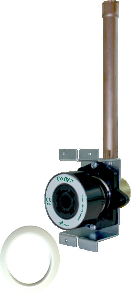
3 Product Description The Amico Medical Gas British Outlet Slim Style is composed of two separated modules: the Rough-in Assembly and the Latch-Valve Assembly. The Rough-in Assembly consists of a brass machined body that incorporates a spring loaded check assembly. The copper pipe is sliver brazed into the body and flared to 12 mm inside diameter for external pipeline connections. The brass body and pipe assembly are inserted in to a gas specific plate. The Rough-in Assembly has a colour coded label on the front plate and the copper pipe, so that the installer can easily identify the gas that the copper pipe should be connected to. The Rough-in Assembly incorporated a check valve that allows the Latch-Valve Assembly to be removed for service, without requiring the pipeline to be shut down. The Rough-in Assembly has a DUAL pin gas specific indexing arrangement to prevent the wrong Latch-Valve assembly from being plugged into the Rough-in Assembly (see page 17). The Latch-Valve Assembly is manufactured with a gas specific housing which accepts, retains and releases the probe, indexed on the back side to match gas specific indexing of the Rough-in Assembly. CAUTION: DO NOT over tighten the Latch-Valve mounting screws! Distortion of the Latch-Valve can occur. Outlets are available for oxygen, medical air, surgical air, nitrous oxide, medical vacuum and anesthetic gas scavenging system. These are designed in accordance with HTM and ISO Cleaning and Lubrication The Amico British Slim Style Outlets are factory cleaned for oxygen service. Exposed surfaces of the Outlet may be cleaned with a mild detergent solution or wiped with a disinfectant commonly used in patient rooms, which is compatible with plastic, anodized aluminum and die cast zinc. Lubricate elastomer seals sparingly with silicone lubricant that is oxygen compatible. DO NOT USE OIL 3
4 Inspection and Testing Pressure drops across the Amico British Outlet shall comply with ISO 9170 Standards. Terminal Unit Nominal Distribution Pressure (kpa) Test Pressure (kpa) Test Flow (1/min) Maximum Pressure Drop Across a Terminal Unit (kpa) 400 to to to 1, * Absolute pressure Vacuum * AGSS Requirements for flow and pressure drop across terminal units with probe inserted ISO 9170 Standards. Terminal Type Test Pressure Test Flow (1/min) Maximum Pressure Drop Across a Terminal Unit (kpa) 1 Atmospheric pressure Note: The Amico British Slim Style Outlets meet and exceed the requirements at the time of manufacture. However piping source capacity, sizing and restrictions my prevent outlets form attaining these values. Installation and Dimensions The Amico British Slim Style Outlet should be mounted at a height of between 900 mm and 1400 mm above finished floor level and not less than 200 mm from any obstruction. Where more than one Outlet unit is to be mounted in one location, these should be mounted at the following spacing; Two Outlet units 150 mm centres Three or more Outlets units 135 mm centres Outlet units mounted in a horizontal array shall be installed in the following sequence when viewed from the front, left to right; O₂ N₂O; 50% O₂/50% N₂O; Medical Air, Surgical Air, Vacuum; AGSS Please refer to HTM Amico Corporation
5 Installation and Dimensions Console Mount 5
6 Installation and Dimensions Surface Mount 6 Amico Corporation
7 Preventative Maintenance Regular inspection and maintenance of the Outlets will prolong its life and reduce the possibility of sudden, inconvenient component failures. The use of damage probes or faulty equipment may require further maintenance. Outlets should be subjected to regular inspection and testing as follows: Monthly; a. Visually inspect the Outlet for signs of damage. b. Check to see if the Front Latch Assembly (2nd Fix) operates smoothly with the gas specific probe. c. If there is any disagreement with the operation of the Front Latch Assembly (2nd Fix), remove the unit for closer inspection/repair/replacement if necessary. Annually; a. Remove Trim Plate and clean debris from the mounting box. b. Remove Front Latch Assembly (2nd fix) and inspect the barrel for any damage. c. Inspect the Rough-in Assembly (1st fix) for any damage. If damage or leaking replace components. d. Test Front Latch Assembly (2nd fix) for correct operation (connection and disconnection of the probe) using a blank probe. 7
8 Gas Latch-Valve Assembly Unscrew the two Surface Box Cover screws (1), and remove the Surface Box Cover (2), or pry off Trim Ring (3) with a flat screw driver. 2. Unscrew the two Retaining screws (5) until the Latch-Valve Assembly (4) can be removed from the Outlet. 3. Remove the two Retaining washer screws (11), and remove the Retaining washer (10). 4. Remove the Gas Connector (8) 5. Remove the Body Seal (6), and the Poppet O-Ring (9), then the Poppet (7) from the front of the Gas Connector (8). Inspect the items for wear or damage and replace if needed. 6. Re-install all internal components into the Gas Connector (8). Poppet (7), then install Poppet O-Ring (9), then inset Body Seal (6) are in place. Re-install the round Retaining washer (10) and secure with two Retaining washer screws (11), do not over tighten. 7. Re-install the Latch-Valve Assembly into the outlet. Coat the Gas Connector (8) with a thin coat of oxygen compatible silicone lubricant to aid insertion. Tighten down the Retaining screws (5), DO NOT over tighten, as this could damage the Latch-Valve Assembly 8. Re-install Surface Box Cover (2), install Surface Box screws (1) and tighten down (DO NOT OVER TIGHTEN) or reinstall Trim Ring (3). 9. Connect gas specific adapter into the outlet. The connection should be smooth and the adapter should lock and remain in place allowing gas to flow. If not, replace the entire Latch-Valve Assembly (4). 8 Amico Corporation
9 Vacuum Latch-Valve Assembly NOTE: Suction Outlets do not have a secondary check valve. Suction source to the Vacuum Outlet must be turned off before removing the Latch-Valve Assembly 1. Unscrew the two Surface Box Cover screws (1), and remove the Surface Box Cover (2), or pry off Trim Ring (3) with a flat screw driver. 2. Unscrew the two Retaining screws (5) until the Latch-Valve Assembly (4) can be removed from the Outlet. 3. Remove the Primary Vacuum Spring (12), and inspect for damage replace if needed. 4. Remove the two Retaining washer screws (11), and remove the Retaining washer (10). 5. Remove the Gas Connector (8) 6. Remove the Body Seal (6), and the Poppet O-Ring (9), then the Poppet (7) from the front of the Gas Connector (8). Inspect the items for wear or damage and replace if needed. 7. Re-install all internal components into the Gas Connector (8). Poppet (7), then install Poppet O-Ring (9), then inset Body Seal (6) are in place. Re-install the round Retaining washer (10) and secure with two Retaining washer screws (11), do not over tighten. 8. Re-install the Primary Vacuum Spring (12). 9. Re-install the Latch-Valve Assembly into the outlet. Coat the Gas Connector (8) with a thin coat of oxygen compatible silicone lubricant to aid insertion. Tighten down the Retaining screws (5), DO NOT over tighten, as this could damage the Latch-Valve Assembly 10. Re-install Surface Box Cover (2), install Surface Box screws (1) and tighten down (DO NOT OVER TIGHTEN) or reinstall Trim Ring (3). 11. Connect gas specific adapter into the outlet. The connection should be smooth and the adapter should lock and remain in place allowing gas to flow. If not, replace the entire Latch-Valve Assembly (4). 9
10 AGSS Latch-Valve Assembly Unscrew the two Surface box Cover screws (1), and remove the Surface Box Cover (2), or pry off Trim ring (3) with a flat screw driver. 2. Unscrew the two Retaining screws (5) until the Latch-Valve Assembly (4) can be removed from the Outlet. 3. After removing the Latch-Valve Assembly (4) from the Outlet, you can then pull the Check Valve Body Assembly from the back side of the Latch-Valve Assembly (4). Remove the Check Valve Body Seals (10 & 11) and check for any abnormal wear or Damage and replace if needed. Coat the O-Ring with a thin coat of oxygen compatible silicone lubricant. 4. Disassembly of the Check Valve Body Assembly: Hold the Check Valve Assembly in one hand, and push down the Check Valve (6) with your thumb of the same hand, compressing the Check Valve Spring (9). Remove the Check Valve O-Ring (13). Release the Check Valve (6) slowly; The Check Valve Body Assembly will fall apart. Inspect parts for abnormal damage or wear and replace. 5. Reassembly of the Check Valve Body Assembly: Re-install the Check Valve Spring (9) onto the Check Valve (6), and then insert them into the Check Valve Body (12). Again, hold the Check Valve Body Assembly in one hand, and push down the Check Valve (6) with your thumb of the same hand, compressing the Check Valve Spring (9). Before reinstalling the Check Valve O-Ring (13), coat the O-Ring with a thin coat of oxygen compatible silicone lubricant. 6. Insert the Check Valve Body Assembly into the back of the Latch-Valve Assembly. 7. Re-install the Latch-Valve Assembly into the outlet. Coat the outer portion of the Check Valve Body Assembly with a thin coat of oxygen compatible silicone lubricant, to aid insertion. Tighten down Retaining Screws (5). DO NOT over tighten, as this could damage the Latch-Valve. 8. Re-install Surface Box Cover (2), install Surface Box screws (1) and tighten down (DO NOT OVER TIGHTEN) or reinstall Trim Ring (3). 9. Connect gas specific adapter into the outlet. The connection should be smooth and the adapter should remain in place allowing flow. If not, replace the entire Latch-Valve Assembly (4). 10 Amico Corporation

11 AGSS Flow Control Adjustment Referencing Part Numbers: O-BSQSL-SUR-AGS O-BSQSL-CON-AGS A.G.S.S. Threaded Nose Valve Flow Control Screw (3mm Allen Key) Surface Mount Box 1. Insert a 3 mm Allen Key into the front of the Check Valve. 2. Adjust the Flow Control Screw to desired setting. 11
12 Rough In Assembly CAUTION: Ensure that the supply pressure is shut off before performing service. Inside the Rough-in Assembly is a secondary check valve whose function is to shut off gas flow when the Latch-Valve Assembly is removed. This seal O-Ring also prevents leakage around the latch-valve connector. As the secondary seal is only a static seal, it will rarely need replacement. However, if the seal O-Ring does need replacement, follow the following procedure: NOTE: Suction inlets (Vacuum and AGSS) are not supplied with Secondary Check Valve. The Secondary Check Valve (2) and Secondary Check Valve Spring (3) are not required. 1. Ensure that no pressure exists in the line by depressing the secondary check (2). 2. Removal of Internal components: Depress the Secondary Check Valve (2), with a dull screw driver (prevents damage on the Check Valve), at the same time pry out the Secondary Seal O-Ring (1), with a small screws driver. After the Secondary Seal O-Ring (1) is out. The Secondary Check Valve (2) and Secondary Check Valve Spring (3) are no longer locked in place and can be easily removed. Inspect all components for abnormal wear and replace. 3. Reinstallation if internal components: Install the Secondary Check Valve Spring (3) to the back side for the Secondary Check Valve (2). Then insert into the Rough-in Body (4). Insert Secondary Seal O-Ring (1), while depressing the Secondary Check Valve (2). 4. Turn on the pressure and check for leaks. Re-install the Latch-Valve Assembly and perform then inspection and test. 12 Amico Corporation
13 Model Numbers Surface Mounted Latch-Valve Assembly Rough-in Assembly Complete Assembly Oxygen O-FASC-BSQSL-OXY O-BAKSUR-BSQSL-OXY O-BSQSL-SUR-OXY Medical Air O-FASC-BSQSL-AIR O-BAKSUR-BSQSL-AIR O-BSQSL-SUR-AIR Surgical Air O-FASC-BSQSL-SAI O-BAKSUR-BSQSL-SAI O-BSQSL-SUR-SAI Vacuum O-FASC-BSQSL-VAC O-BAKSUR-BSQSL-VAC O-BSQSL-SUR-VAC Nitrous Oxide O-FASC-BSQSL-N20 O-BAKSUR-BSQSL-N20 O-BSQSL-SUR-N20 Anaesthetic Gas Scavenging System O-FASC-BSQSL-AGS O-BAKSUR-BSQSL-AGS O-BSQSL-SUR-AGS Console Mounted Latch-Valve Assembly Rough-in Assembly Complete Assembly Oxygen O-FASC-BSQSL-OXY O-BAKSUR-BSQSL-OXY O-BSQSL-SUR-OXY Medical Air O-FASC-BSQSL-AIR O-BAKSUR-BSQSL-AIR O-BSQSL-SUR-AIR Surgical Air O-FASC-BSQSL-SAI O-BAKSUR-BSQSL-SAI O-BSQSL-SUR-SAI Vacuum O-FASC-BSQSL-VAC O-BAKSUR-BSQSL-VAC O-BSQSL-SUR-VAC Nitrous Oxide O-FASC-BSQSL-N20 O-BAKSUR-BSQSL-N20 O-BSQSL-SUR-N20 Anaesthetic Gas Scavenging System O-FASC-BSQSL-AGS O-BAKSUR-BSQSL-AGS O-BSQSL-SUR-AGS 13
14 Gas Indexing As seen from the front of the Rough-In Assemblies VACUUM OXYGEN NITROUS OXIDE MEDICAL AIR SURGICAL AIR AGSS 14 Amico Corporation
15 Replacement Components Gas and Vacuum Latch-Valve Assembly Item Description Model Numbers 1 Surface Box Cover screws (2 req'd) H-STPP-6150AB 2 Surface Box Cover O-X-BSQC-SBX Trim Ring O-X-BSQC-FACTRM2 4 British Standard Slim Style Latch-Valve See Above 5 Outlet Retaining Mounting screws (2 req'd) H-MPP Body Seal O-X-OXE-SEAT* 7 Poppet O-X-BSQC-POPET2* 8 Gas connector O-X-BSQC-VLV2 9 Poppet O-Ring H-ORING105VTN* 10 Retaining washer O-X-BSQC-WASH 11 Retaining washer screws (2 req'd) H-HLTPP Vacuum spring (Only used for Vacuum Outlet) O-X-LVAPB-SPGAS* Above parts with and * are found in repair kit: O-RK-LVA-BSQSL 15
16 Replacement Components AGSS Latch-Valve Assembly Item Description Model Numbers 1 Surface Box Cover screws (2 req'd) H-STPP-6150AB 2 Surface Box Cover O-X-BSQC-SBX Trim Ring O-X-BSQC-FACTRM2 4 British Standard Slim Style Latch-Valve See Above 5 Outlet Mounting screws (2 req'd) H-MPP AGSS Check Valve O-X-BSQC-CHKVLV 7 Flow Adjustment screw H-HSSS-CPM601-6SS 8 Locking screw H-HSSS-CPM601-6SS 9 AGSS Check Valve Spring O-X-BSQC-VLV-SPR* 10 Check Valve Body Seal H-ORING-020VTN* 11 Check Valve Body Seal H-ORING-020VTN* 12 Check Valve Body O-X-BSQC-LATCH2 13 Check Valve O-Ring O-X-LVAQ-ORING* Above parts with and * are found in repair kit: O-RK-LVA-BSQSL-AGS 16 Amico Corporation
17 Replacement Components Rough-in Assembly Item Description Model Numbers 1 Secondary Seal O-Ring H-ORING-115VTN* 2 Secondary Check Valve O-X-BSQC-BKCHK2* 3 Secondary Check Valve Spring O-X-BSQC-BAKSPR* 4 Rough-in Body See above Above parts with an * are found in repair kit: O-RK-BAK-BSQSL 17
18 Amico Corporation 85 Fulton Way, Richmond Hill Ontario, L4B 2N4, Canada Toll Free Tel: Toll Free Fax: Tel: Fax: Authorized Representative: RMS-UK Limited 28 Trinity Road Nailsea, Somerset BS484NU England Phone & Fax: APE-INSTAL-MANI-BRIT-STD-OUTLET-SLM
Installation and Maintenance Manual. Medical Gas Outlet. British Standard Compatible
 Installation and Maintenance Manual Medical Gas Outlet British Standard Compatible w w w. a m i c o. c o m Table of Contents Product Description 3 Cleaning and Lubrication 3 Inspection and Testing 4 Installation
PRECISION UK Ltd. Medical Gas Outlet BS Standard
 Contents Page Section No. Product Description General 1 First Fix Assembly 1.2 Check Valve Assembly 1.3 Second Fix Assembly 1.4 Operation General 2 Probe Connection/Disconnection 2.2 Safety General 3 Installation
Outlets and Accessories
 Service Manual Series B Quick-Connect and Diameter-Index Safety System Outlets and Accessories MAN0-03 Part No. 803-00 Rev. D Pg. Table of Contents General Product Description...3 Tools and Service Materials...
Axis MEDICAL GAS TERMINAL UNITS
 Axis MEDICAL GAS TERMINAL UNITS Phoenix Pipeline Products Limited. Unit 8, McKenzie Industrial Park, Tel No.: 44 (0) 161 428 7200 Bird Hall Lane, Fax No.: 44 (0) 161 428 7010 Stockport, Email: info@p3-phoenix.com
Axis AGSS TERMINAL UNITS
 Axis AGSS TERMINAL UNITS. Unit 8, McKenzie Industrial Park, Tel No.: 44 (0) 161 428 7200 Bird Hall Lane, Fax No.: 44 (0) 161 428 7010 Stockport, Email: info@p3-phoenix.com U.K., SK3 0SB www.p3-phoenix.com
FLEXIBLE PENDANTS with Axis MEDICAL GAS TERMINAL UNITS
 FLEXIBLE PENDANTS with Axis MEDICAL GAS TERMINAL UNITS Phoenix Pipeline Products Limited. Unit 8, McKenzie Industrial Park, Tel No.: 44 (0) 161 428 7200 Bird Hall Lane, Fax No.: 44 (0) 161 428 7010 Stockport,
Service Manual Gemini, Diamond II and Diamond III Medical Gas Outlets for Concealed Piping and Console Applications
 Service Manual Gemini, Diamond II and Diamond III Medical Gas Outlets for Concealed Piping and Console Applications MAN0-049 Part number 847706-00 Rev. C00 Table of Contents General Product Description...
RIGID PENDANT. Phoenix Pipeline Products Limited. Installation, Operation and Maintenance Manual
 RIGID PENDANT Phoenix Pipeline Products Limited. Unit 8, McKenzie Industrial Park, Tel No.: 44 (0) 161 428 7200 Bird Hall Lane, Fax No.: 44 (0) 161 428 7010 Stockport, Email: info@p3-phoenix.com U.K.,
Gemini, Diamond II and Diamond III Medical Gas Outlets for Concealed Piping and Console Applications
 Service Manual Gemini, Diamond II and Diamond III Medical Gas Outlets for Concealed Piping and Console Applications Andersen Medical Gas Place Lafitte Madisonville, LA 70447 http://www.themedicalgas.com
Technical Datasheet. SP Terminal Units. Classification. Services. Terminal Block. Check Valve Assembly. Tailpipe Options
 SP Terminal Units Pneumatech MGS East & Zeus SP terminal units provide a safe means of supplying medical equipment with medical gases from the central gas supply system. They are manufactured to accept
At Amico Labs we are dedicated to continued growth while producing products of outstanding quality, and providing excellent service.
 1 ABOUT US Amico Corporation is a leading manufacturer of Medical Equipment, selling its products through a global distribution channel from three manufacturing facilities in Canada and the U.S. With a
PRECISION UK Ltd DUPLEX AGSS PLANT
 DUPLEX AGSS PLANT Contents Page Section Page Product Description General 3 AGSS Plant 3 AGSS Remote Switch 3 Operation General 4 Safety General 5 Installation General 5 Mechanical 5 Electrical 7 Wiring
Pressure Switch with Gauge for Pressure
 Pressure Switch with Gauge for Pressure General Specifications: Pressure Gauge Assembly for the medical gas alarm system shall incorporate a U.L. Listed single pole double throw snap-action micro switch.
CEGA FORANO BY GREGGERSEN
 CEGA FORANO BY GREGGERSEN PRODUCT CATALOG FORANO Terminal Unit According to DIN EN ISO 9170-1 GENERAL According to national and international standards, The unit is used to withdraw compressed gases and
Condor Manual. Corporation
 Condor Manual Corporation PREFACE IMPORTANT, PLEASE READ CAREFULLY Thank you for your purchase with Amico Accessories Inc. This unit is designed for long lasting performance, providing the end user complies
Technical Specification
 Technical Specification Agss Plant Product Description Active anesthetic gas scavenging systems should be designed to safely remove exhaled anesthetic agents from the operating environment and dispose
RETRACTABLE CEILING COLUMN
 RETRACTABLE CEILING COLUMN Installation Manual RETRACTABLE CEILING COLUMN INTRODUCTION Location, sequence of services and orientation of Surgical Ceiling Columns are specified on the building plans. Be
Operating & Maintenance Manual. Automatic Medical Gas Manifold Digital Dome Loaded Regulator NFPA v1.5
 Operating & Maintenance Manual Automatic Medical Gas Manifold Digital Dome Loaded Regulator NFPA v1.5 Contents User Responsibility 4 Introduction 5 Features 5 Description of the Manifold 6 Shipment Details
Automatic Medical Gas Manifold Dome Loaded Regulator NFPA v1.1
 Operating & Maintenance Manual Automatic Medical Gas Manifold Dome Loaded Regulator NFPA v1.1 w w w. a m i c o. c o m Contents User Responsibility 4 Introduction 5 Features 5 Description of the Manifold
V4043 and V4044 Motorized Valves
 V03 and V0 Motorized Valves INSTALLATION INSTRUCTIONS FEATURES V0 These valves consist of an actuator motor and valve assembly for controlling the flow of hot or cold water. The V03 provides 2-position,
Spectra EA Series. the right connection. product benefits. Horizontal positioning radius of 81 (205 cm) Vertical positioning range of 27 (68 cm)
 Vertical positioning range of 27 (68 cm)") Clinical Spectra EA Series Horizontal positioning radius of 81 (205 cm) Vertical positioning range of 27 (68 cm) Rotation of 350º degrees with adjustable stops Maximum carrying capacity of 251 lbs. (114
Clinical Spectra EA Series Horizontal positioning radius of 81 (205 cm) Vertical positioning range of 27 (68 cm) Rotation of 350º degrees with adjustable stops Maximum carrying capacity of 251 lbs. (114
Servicing Instructions
 Servicing Instructions Therapy Equipment Pipeline Suction Range Revision 5 : June 2013 CONTENTS Section No. 1 Record of Permanent Revisions 2 Pipeline Suction Product Information 3 Annual Function Test
Installation Instructions. ARS (Amico Rail Systems)
") Installation Instructions ARS (Amico Rail Systems) w w w. a m i c o. c o m Preface Important, Please Read Carefully Thank you for your purchase with Amico Accessories Inc. This unit is designed for long
Installation Instructions ARS (Amico Rail Systems) w w w. a m i c o. c o m Preface Important, Please Read Carefully Thank you for your purchase with Amico Accessories Inc. This unit is designed for long
6 Bay Battery Charger Operation Manual
 6 Bay Battery Charger Operation Manual Sunoptic Technologies 6018 Bowdendale Avenue Jacksonville, FL 32216 USA Customer Service: 904 737 7611 Toll Free 877 677 2832 EC REP RMS UK, Ltd. 28 Trinity Road
Hospital Bed Collection. Amico Care Series Mobility - Simplicity - Versatility
 Hospital Bed Collection Amico Care Series Mobility - Simplicity - Versatility w w w. a m i c o. c o m Apollo MS MedSurg Bed Standard Features 6 inch Tente wheel casters Central locking brake mechanism
OPERATING MANUAL POWER DRIVE SYSTEM. Cat. No RevH
 OPERATING MANUAL POWER DRIVE SYSTEM Cat. No. 400005 525-1300-00 RevH System components Symbol Definitions Qty Description Catalog Number 1 Power Drive System 300106 1 Controller 300108 1 Cutter Drive
Stretchers. Titan Transport and Titan Bariatric
 Stretchers Titan Transport and Titan Bariatric w w w. a m i c o. c o m Designed for Caregivers to Provide More Care with Less Effort The Amico Titan Stretcher uses an innovative design and incorporates
The world's smallest 700 lb patient lift... Weighs less than 10 lbs!
 Safety in Motion The world's smallest 700 lb patient lift... Weighs less than 10 lbs! Ceiling Lift Motors Application The primary purpose of a ceiling lift system is to safely lift, transfer and reposition
TECHNICAL DATA. Viking Technical Data may be found on Style: 90 Degree Pattern (inlet to outlet)
") Flow Control 500a DESCRIPTION The Viking 1-1/2 is a quick opening, differential type flood valve with a spring loaded rolling diaphragm clapper. The can be used to facilitate manual or automatic on/off
Flow Control 500a DESCRIPTION The Viking 1-1/2 is a quick opening, differential type flood valve with a spring loaded rolling diaphragm clapper. The can be used to facilitate manual or automatic on/off
Installation Operation Maintenance
 Installation Operation Maintenance www.challengervalves.com.au 1 QAD#IM1015 REVC 3.10.15 Index 1. INTRODUCTION 3 1.1 Design Features 1.2 Flange and Pipe Compatibility 3 1.3 Operating Pressures and Temperatures
Installation Operation Maintenance. LSSN Butterfly Valve AGA Approved 50MM - 150MM. QAD#IM6055.REVA
 LSSN Butterfly Valve Installation Operation Maintenance Licence Number: 5326 www.challengervalves.com.au 1 Index 1. INTRODUCTION 1.1 Design Features 3 1.2 Flange and Pipe Compatibility 4 1.3 Operating
Welker Adjustable Probe with Check Valve and Welker Automatic Insertion Probe with Check Valve
 a Installation, Operation, & Maintenance Manual Welker Adjustable Probe with Check Valve and Welker Automatic Insertion Probe with Check Valve Models AP-3MI & AIP-3MI The information in this manual has
A-320 Balanced 1st Stage
 Technical Manual A-320 Balanced 1st Stage A Manual for Repair and Maintenance Technicians View: Select Full Screen mode to use page arrows. FEATURES Extra durable satin chrome plated brass body. Fully
LLS-2054BE. Smart Battery Pack Operator Manual. ST Technologies 6018 Bowdendale Avenue Jacksonville, FL USA
 LLS-2054BE Smart Battery Pack Operator Manual ST Technologies 6018 Bowdendale Avenue Jacksonville, FL 32216 USA Customer Service: 904 208-2290 Toll Free 877-814-2237 EC REP RMS UK, Ltd. 28 Trinity Road
1 - S-2251 Showerhead 6 - S-2288 Showerhead AP - Anchor Plate (S-2280 Showerhead Only)
") SPEAKMAN COMPANY Sentinel Pro Thermostatic/Pressure Balancing Valve, Showerhead, Tub Spout, & Combo Series Installation, Operation, & Maintenance Instructions DESCRIPTION Speakman Sentinel Pro concealed
SPEAKMAN COMPANY Sentinel Pro Thermostatic/Pressure Balancing Valve, Showerhead, Tub Spout, & Combo Series Installation, Operation, & Maintenance Instructions DESCRIPTION Speakman Sentinel Pro concealed
Welker Sampler. Installation, Operation, & Maintenance Manual. Model GSS-4HP
 Installation, Operation, & Maintenance Manual Welker Sampler Model GSS-4HP The information in this manual has been carefully checked for accuracy and is intended to be used as a guide to operations. Correct
Parker Hannifin Corporation Porter Instrument Division 245 Township Line Road Hatfield, PA USA Tel: Ref.
 Parker Hannifin Corporation Porter Instrument Division 245 Township Line Road Hatfield, PA 19440 USA Tel: 215-723-4000 Ref. 10489600 Rev F SAFETY SUMMARY CAUTIONS Federal Law in the U.S.A. and Canada
Temperature Sensor Series
 GENERAL DESCRIPTION The patented* No. 85026-Series Temperature Sensor contains a two-position valve operated by temperature variations around the integral sensing bulb. It is used to vent or block a pneumatic
Installation, Operation, and Maintenance Manual
 Installation, Operation, and Maintenance Manual Welker Automatic Insertion Heated Regulator High Voltage Model IHRA-4SS-220/230 100 or more inch insertion length The information in this manual has been
INSTALLATION, OPERATION AND MAINTENANCE MANUAL
 INSTALLATION, OPERATION AND MAINTENANCE MANUAL LUDLOW SERIES FIGURE 350-W 3 to 24 Lever & Weight Air-Cushioned Swing Check Valves TABLE OF CONTENTS Introduction. 1 Description of Operation... 1 Receiving
Welker Gas Sampler Model MPS-2
 Installation, Operation, and Maintenance Manual Welker Gas Sampler Model MPS-2 The information in this manual has been carefully checked for accuracy and is intended to be used as a guide to operations.
SERVICE MANUAL. DiamondCare Recessed Wall Outlet and Electrical. MAN Rev. B
 SERVICE MANUAL DiamondCare Recessed Wall Outlet and Electrical Andersen Medical Gas 12 Place Lafitte Madisonville, LA 70447 http://www.themedicalgas.com 1-866-288-3783 MAN01-045 Rev. B 2004 by BeaconMedæs.
Welker Probe Instrument Regulator with Liquid Eliminator Cartridge
 Installation, Operation, & Maintenance Manual Welker Probe Instrument Regulator with Liquid Eliminator Cartridge Model LEFRD-4SS The information in this manual has been carefully checked for accuracy and
TILLOTSON LTD., CLASH INDUSTRIAL ESTATE, TRALEE, CO. KERRY, IRELAND PHONE: FAX:
 TILLOTSON LTD., CLASH INDUSTRIAL ESTATE, TRALEE, CO. KERRY, IRELAND PHONE: +353 66 7121911 FAX: +353 66 7124503 e-mail: sales@tillotson.ie SERIES SERVICE MANUAL INTRODUCTION The gasoline engine industry
Types 1808 and 1808A Pilot-Operated Relief Valves or Backpressure Regulators
 Instruction Manual Form 5116 Types 1808 and 1808A July 2010 Types 1808 and 1808A Pilot-Operated Relief Valves or Backpressure Regulators! Warning Failure to follow these instructions or to properly install
Steam/Water Washdown Units Safety and Operation Installation and Maintenance Instructions
 INSTALLATION AND MAINTENANCE INSTRUCTIONS IM-8-002-US October 2016 Steam/Water Washdown Units Safety and Operation Installation and Maintenance Instructions These instructions should be read by the Company
Model INTERNAL/BOTTOM LOADING VALVES SM Maintenance & Repair Manual. July Applicable addition manuals: None
 SM64128 July 2010 Eaton Aerospace Group Conveyance Systems Division Carter Brand Ground Fueling Equipment Applicable addition manuals: None Maintenance & Repair Manual 6 INTERNAL/BOTTOM LOADING VALVES
MEMORY SEAL BALL VALVES MAINTENANCE MANUAL 2 12, Class 150 & 300, Regular Port, Flanged Unibody
 MEMORY SEAL BALL VALVES MAINTENANCE MANUAL 2 12, Class 150 & 300, Regular Port, Flanged Unibody I INTRODUCTION These rugged, versatile, high performance, regular port, ball valves meet all requirements
2200 North Main Street Washington, PA PH: FX:
 2200 North Main Street 2200 North Main Street KVAB SERIES MEDICAL VALVES All valves MRI compatible - approved to 3 Tesla. Nominal stroke is 1.5 turns. Full flow at ⅓ turn. Strong, durable body is made
CAB TILT HYDRAULIC SYSTEM
 OPERATION, MAINTENANCE and SERVICE INSTRUCTIONS CAB TILT HYDRAULIC SYSTEM WITH POWER-PACKER PUMP, CYLINDERS and LATCHES A division of Actuant Corporation 1-800-745-4142 1 www.powerpackerus.com Notice The
Temperature Regulators
 Temperature Regulators DESIGN & OPERATION DIAL THERMOMETER (Model 91400 only) BELLOWS OVERRANGE PROTECTION SPRING CAPILLARY TUBING CONNECTION SENSING BULB RANGE ADJUSTMENT SPRING CAP ADJUSTMENT SCREW BUSHING
DECLARATION OF CONFORMITY FOR THE MEDICAL DEVICE FAMILY OUTLETS FOR COMPRESSED MEDICAL GASES AND VACUUM AND FOR ANAESTHETIC GAS SCAVENGING SYSTEMS
 DECLARATION OF CONFORMITY FOR THE MEDICAL DEVICE FAMILY OUTLETS FOR COMPRESSED MEDICAL GASES AND VACUUM AND FOR ANAESTHETIC GAS SCAVENGING SYSTEMS whose codes are specified in the attachment, to the essential
Service Handbook High-Pressure Washer Pump
 Service Handbook High-Pressure Washer Pump 9.120-014.0 2 A. Water Inlet Filter C. Nozzle Insert 1. Remove filter with a screwdriver. 2. Clean filter with warm water and mild soap. 3. Reinstall filter.
T60 REGULATOR REPAIR KIT INSTRUCTIONS
 T60 REGULATOR REPAIR KIT INSTRUCTIONS This PPI covers the repair of Series I and II T60 regulators using either a minor or major repair kit. Important: Any maintenance, service or repair should be performed
DCell Suction. Model DM Operating Instructions & Maintenance Manual. Clearing The Airway Is Our #1 Priority
 DCell Suction Model DM10-001 Clearing The Airway Is Our #1 Priority Operating Instructions & Maintenance Manual, INC. 11064 Randall Street Sun Valley, CA 91352 USA www.sscor.com Email: marketing@sscor.com
Welker Automatic Insertion Diffusing Probe Model AIP-3DP
 Installation, Operation, and Maintenance Manual Welker Automatic Insertion Diffusing Probe Model AIP-3DP The information in this manual has been carefully checked for accuracy and is intended to be used
6200 Series. Specifications. Fluid End Power End Models 6211, 6212, 6221, & 6222 Models 6241 & 6242 Part Material Part Material Part Material
 5.2018.12.i 6200 Series Specifications The Flomore 6200 Series Pump line consists of a series of basic pump options all developed from a modular power unit. All units are pneumatically driven positive
Operating Instructions. International English. CCS Dust Extractor
 Operating Instructions International English CCS Dust Extractor Electric Cast Saw Dust Removal System Warnings & Safety Rules WARNING!: THIS EQUIPMENT MUST BE EARTHED! Danger!: Possible explosion hazard
No Infrared Refrigerant Leak Detector
 No. 22791 Infrared Refrigerant Leak Detector Operator s Manual Product Description The Robinair No. 22791 uses infrared optics to create a refrigerant leak detector that combines sensitivity, speed, battery
TECHNICAL DATA 1-1/2 (dn40)
") July 1, 2011 Deluge Valves 209a DESCRIPTION The Viking Model E-3 1-1/2 Deluge Valve is a quick-opening, differential type flood valve with a rolling diaphragm clapper. The deluge valve is used to control
July 1, 2011 Deluge Valves 209a DESCRIPTION The Viking Model E-3 1-1/2 Deluge Valve is a quick-opening, differential type flood valve with a rolling diaphragm clapper. The deluge valve is used to control
Type 289P Pilot-Operated Relief Valve
 Instruction Manual D102680X012 Type 289P July 2017 Type 289P Pilot-Operated Relief Valve Figure 1. 1 NPT Type 289P Pilot-Operated Relief Valve Figure 2. 2 NPT Type 289P Pilot-Operated Relief Valve Introduction
250L Cartridge Dual Seal
 INSTALLATION, OPERATION AND MAINTENANCE INSTRUCTIONS 250L Cartridge Dual Seal Installation, Operation and Maintenance Instructions TABLE OF CONTENTS 1.0 Cautions...2 2.0 Transport and Storage...2 3.0 Description...2
5020 Series Injector
 5.2018.9.k 1 5020 Series Injector 1 2 3 4 5 6 10 11 7 12 13 8 2 14 Parts List 15 16 17 Item # Part # # Reqd. Description Material Alternate Part # 1 A-1854 1 0-12 PSI Pressure Gauge A-1295SS 2 A-0022 1
SERVICING INSTRUCTIONS
 TSP Series 66 Triplex Plunger Pump SERVICING INSTRUCTIONS TRIPLEX TRIPLEX SERVICING PUMP PROCEDURES Valve Replacement: All inlet and discharge valves can be serviced without disrupting the inlet or discharge
Maintenance & Repair Manual
 SM64055 November 2012 Aerospace Group Conveyance Systems Division Applicable additional manuals: None Carter Brand Ground Fueling Equipment Maintenance & Repair Manual 4 Inch Internal/Bottom Loading Valves
Model 210HP Beadbreaker
 00020HP:99900657: 2040409 Model 20HP Beadbreaker PARTS AND SERVICE MANUAL IOWA MOLD TOOLING CO., INC. BOX 89, GARNER, IA 50438-089 TEL: 64-923-37 TECHNICAL SUPPORT FAX: 64-923-2424 MANUAL PART NUMBER 99900657
Series 957, 957N, 957Z, 957RPDA, 957NRPDA, 957ZRPDA
 Series 957, 957N, 957Z, 957RPDA, 957NRPDA, 957ZRPDA Reduced Pressure Zone Assemblies Reduced Pressure Detector Assemblies Sizes: 2 1 2" 10" (65 250mm) Installation Service Repair Kits Maintenance RP/IS-957/957RPDA
Maintenance Information
 16572679 Edition 2 May 2014 Air Drill QP Series Maintenance Information Save These Instructions Product Safety Information WARNING Failure to observe the following warnings, and to avoid these potentially
CYLINDER VALVES. Assembly & Maintenance Guide
 CYLINDER VALVES Assembly & Maintenance Guide TABLE OF CONTENTS Topic Page Yoke Connection Valves...................................2 6300 Series Valves.......................................3 Service Procedures.......................................4
Troubleshooting the Transmission Hydraulic System
 Testing and Adjusting IT28F INTEGRATED TOOLCARRIER POWER TRAIN Testing And Adjusting Introduction Reference: For Specifications with illustrations, refer to SENR5974, IT28F Integrated Toolcarrier Power
TECHNICAL DATA OBSOLETE
 April 13, 2007 Spray Nozzle 31a 1. DESCRIPTION Viking Frame Style Spray Nozzles are small, directional spray nozzles for use on water spray systems. They are thermosensitive glass bulb style nozzles, however
INSTALLATION, OPERATION AND MAINTENANCE MANUAL
 INSTALLATION, OPERATION AND MAINTENANCE MANUAL LUDLOW SERIES FIGURE 340-S 3 to 14 Lever & Spring Swing Check Valves TABLE OF CONTENTS Introduction. 1 Description of Operation... 1 Receiving & Storage...
Installation Guidelines
 STYLE No. CODE No. GUPB81 GUSV81R IMPORTANT: To ensure this product is installed properly, you must read and follow these guidelines. STYLE No. CODE No. GUPB87 (with Diverter) GUSV87R The owner/user of
Installation Instructions
 ARIANA IN WALL PRESSURE BALANCING BATH AND SHOWER SETS Installation Instructions 0 0 Thank you for selecting American-Standard...the benchmark of fine quality for over 00 years. To ensure that your installation
INSTALLATION, OPERATION, AND MAINTENANCE MANUAL WELKER PROBE MOUNTED LIQUID ELIMINATOR
 INSTALLATION, OPERATION, AND MAINTENANCE MANUAL WELKER PROBE MOUNTED LIQUID ELIMINATOR MODEL LE-2SSKO DRAWING NUMBERS AD691BG AD691BGSYS.3 AD691BGSYS.4 AD691CC AD691CD AD691CG AD691CI MANUAL NUMBER IOM-069
Supplies Required. Teflon Tape Allen Key Wrenches Screwdriver 1/2" NPT Brass Pipe Plug Adjustable Wrench IMPORTANT!
 Bradley TMVT1 Thermostatic Mixing Shower Valve ASSE 1016 & UPC Certified For use with shower heads rated at 9.5 L/min (2.5 gpm) or higher. Supplies Required Teflon Tape Allen Key Wrenches Screwdriver Brass
Service Manual Air Tech Second Stage
 Service Manual Air Tech Second Stage Copyright 2002, Cressi-sub Revised 3/2002 2 Air Tech Second Stage Service Manual Contents BEFORE STARTING... 3 DISASSEMBLY... 3 PARTS CLEANING AND LUBRICATION... 9
Model 605 Portable Aspirator
 Model 605 Portable Aspirator CAUTION: USA Federal law restricts this device to sale by or on the order of a physician. #P1000 Rev. 11/02 Table of Contents Specifications 2 Important Parts of the VacuMax
MEDICAL IRRIGATION K PUMP OPERATING MANUAL: Manufactured for: K.M.I 3185 Palisades Dr Corona CA USA Model No.
 OPERATING MANUAL: MEDICAL IRRIGATION K PUMP Manufactured for: K.M.I 3185 Palisades Dr Corona CA 92880-9432 USA 1-866-412-7867 Model No. 1000-0031 A-1299-5091 Edition 01 TABLE OF CONTENTS Title SAFETY PRECAUTIONS
2 CYLINDER MOBILE CART ASSEMBLY INSTRUCTIONS
 Parker Hannifin Corporation Precision Fluidics Division Porter Instrument 245 Township Line Road Hatfield, PA 9440 Office 25-723-4000/Fax 25-723-506 www.porterinstrument.com 2 CYLINDER MOBILE CART ASSEMBLY
Adjustable Differential Relay A1
 Sales Manual Section 332 PRODUCT SPECIFICATION MODEL 84871-A1 GENERAL DESCRIPTION The 84871-A1 Adjustable Differential Diverting Relay is a two-position, snap-acting, three-way relay. Its normal function
Operating & Maintenance Manual For Steam Conditioning Valve
 For Steam Conditioning Valve 1 Table of Contents 1.0 Introduction 3 2.0 Product description 3 3.0 Safety Instruction 4 4.0 Installation and Commissioning 5 5.0 Valve Disassembly 6 6.0 Maintenance 6 7.0
TOYOTA COROLLA LOWERING SPRINGS Preparation
 Preparation Part Number: PTR07-02140 Kit Contents Item # Quantity Reqd. Description 1 2 Front Spring 2 2 Rear Spring 3 1 Hardware 4 1 Instruction Form Hardware Bag Contents Item # Quantity Reqd. Description
EZ-IN Series Turbine Flowmeter
 Class I, Group A, B, C, D, Division I Complies with ASME Standard B31.3 NUFLO EZ-IN Series Turbine Flowmeter Installation Manual Part No. 9A-100062997, Rev. 01 Measurement Systems EZ-IN Series BF Turbine
Wastewater Combination Air Valve. Operation, Maintenance and Installation Manual
 Manual No. WCAV-OM1-1 Wastewater Combination Air Valve Operation, Maintenance and Installation Manual INTRODUCTION... 2 RECEIVING AND STORAGE... 2 DESCRIPTION OF OPERATION... 2 INSTALLATION... 3 VALVE
SV HIGH VACUUM (Positive Relief) SEAL-OFF VALVE 1 Inch Size
 SEAL-OFF VALVE 1 Inch Size") 12501 Telecom Drive, Tampa, FL 33637 Ph: (813) 978-1000 Fax: (813) 977-3329 www.cpc-cryolab.com INSTALLATION, OPERATION, AND MAINTENANCE INSTRUCTIONS 17/1.5.13 Rev. - SV8247-9 HIGH VACUUM (Positive Relief)
12501 Telecom Drive, Tampa, FL 33637 Ph: (813) 978-1000 Fax: (813) 977-3329 www.cpc-cryolab.com INSTALLATION, OPERATION, AND MAINTENANCE INSTRUCTIONS 17/1.5.13 Rev. - SV8247-9 HIGH VACUUM (Positive Relief)
MODEL 905V OPERATING INSTRUCTIONS
 MODEL 905V OPERATING INSTRUCTIONS Quantek Instruments 183 Magill Drive Grafton, MA 01519 Tel: (508) 839-3940 Fax: (508) 819-3444 Email: sales@quantekinstruments.com GENERAL DESCRIPTION These instructions
FkcoqpfEctg Eqpuqng Qwvngv
 UGTXKEG"OCPWCN FkcoqpfEctg Eqpuqng Qwvngv Product No. 6803 Hqt"Rctvu"qt"Vgejpkecn"Cuukuvcpeg Technical Suppt: 1-888-4MEDGAS (463-3427) Customer Service: 1-888-4MEDGAS (463-3427) www.beaconmedaes.com OCP466"Tgx0"C
QA4 Surgery Trolley System Manual Function Operating Instructions
 QA4 Surgery Trolley System Manual Function Operating Instructions Catalogue No. 21310 Anetic Aid Ltd. Queensway Guiseley West Yorkshire, LS20 9JE United Kingdom T +44 (0) 1943 878647 F +44 (0) 1943 870455
Q= C. v P S Refer to Table 1 for part numbers and shipping weights. Accessories: Table 1: Valve Part Numbers and Specifications
 1 of 9 1. DESCRIPTION The Viking Flow Control Valve is a quick opening, differential diaphragm flood valve with a spring loaded floating clapper. The Flow Control Valve can be used to facilitate manual
OPERATION MANUAL. ALUMINUM Models. 316 S.S. Models NTG25 NOMAD TRANS-FLO AIR-OPERATED DOUBLE DIAPHRAGM PUMPS. A JDA Global Company. 1/14 rev.
 OPERATION MANUAL NTG25 NOMAD TRANS-FLO AIR-OPERATED DOUBLE DIAPHRAGM PUMPS ALUMINUM Models 316 S.S. Models A JDA Global Company 1/14 rev. 3 CAUTION SAFETY POINTS TEMPERATURE LIMITS: Neoprene -17.8 C to
MAINTENANCE PROCEDURE FOR MK17
 MAINTENANCE PROCEDURE FOR MK17 MK17 25. juli 2005-1/5 MAINTENANCE PROCEDURE FOR MK 17 1ST STAGE WARNING: this maintenance procedure is only for appointed Scubapro technicians that followed a complete course
Operation, Model MPS-2DA. Installation, responsibility
 Installation, Operation, and Maintenance Manual Welker Double e-acting MPS Bypass Model MPS-2DA Sampler Drawing No.: AD625BP Manual No.: IOM-141 The information in this manual has been carefully checked
Series Roll Seal
 INSTALLATION / OPERATION / MAINTENANCE SERIES 00-4 700 Series Roll Seal DESCRIPTION The Cla-Val Model 00-4 Roll Seal valve is a hydraulically operated valve used to control liquid flow by means of a flexible
M-5000TG/5700TG Steam and Cold Water Mixing Unit
 M-5000TG/5700TG Steam and Cold Water Mixing Unit Installation, Operating and Maintenance Instructions Last Updated: October, 2012 Strahman Valves, Inc. USA Headquarters 2801 Baglyos Circle Bethlehem, PA
SAFETY MANUAL READ FIRST!
 966-05-XX SAFETY MANUAL READ FIRST! IMPORTANT: READ THESE WARNINGS AND SAFETY PRECAUTIONS PRIOR TO INSTALLATION OR OPER- ATION. FAILURE TO COMPLY WITH THESE INSTRUC- TIONS COULD RESULT IN PERSONAL INJURY
TECHNICAL INSTRUCTIONS
 TECHNICAL INSTRUCTIONS 24-Month Maintenance Kit Instructions for RECON 500 / 1000 Water Heaters Flame Detector Kit P/N 24356-2 Ignitor- Injector Kit P/N 58023 Exhaust Manifold Seal P/N GP-122537 Manifold
INSTALLATION, OPERATION, AND MAINTENANCE MANUAL WELKER CRUDE OIL COLLECTION ASSEMBLY HIGH PRESSURE
 INSTALLATION, OPERATION, AND MAINTENANCE MANUAL WELKER CRUDE OIL COLLECTION ASSEMBLY HIGH PRESSURE MODEL AWL-3HP DRAWING NUMBER AD489AP MANUAL NUMBER IOM-116 REVISION Rev. C, 4/6/2018 TABLE OF CONTENTS
AVK SAUDI VALVES MANUFACTURING COMPANY
 AVK SAUDI VALVES MANUFACTURING COMPANY AVK SERIES 24 - HIGH PRESSURE, WET BARREL HYDRANT FIELD MAINTENANCE AND INSTRUCTION MANUAL TABLE OF CONTENTS EXPLODED ASSEMBLY / PARTS LIST INTRODUCTION / DESCRIPTION
Type 289P Pilot-Operated Relief Valve
 Instruction Manual Form 5481 Type 289P February 2012 Type 289P Pilot-Operated Relief Valve W6834 W3167-2 Figure 1. 1 NPT Type 289P Pilot-Operated Relief Valve Figure 2. 2 NPT Type 289P Pilot-Operated Relief