LVU-CD-10 LowViscosity Unit CoaleserDiesel
|
|
|
- Victor Pierce
- 5 years ago
- Views:
Transcription


1 LVU-CD-10 LowViscosity Unit CoaleserDiesel with control type: Standard or Premium Operating and Maintenance Instructions English (translation of original instructions) (Valid Series no. 0002S03302K ) Document No.: a
2 Imprint Imprint Publisher and responsible for the content: HYDAC FILTER SYSTEMS GMBH Postfach Sulzbach / Saarland Germany Telephone: +49 (0) Fax: +49 (0) filtersystems@hydac.com Homepage: Court of Registration: Saarbrücken, HRB Executive director: Mathias Dieter, Dipl.Kfm. Wolfgang Haering Documentation Representative Mr. Günter Harge c/o HYDAC International GmbH, Industriegebiet, Sulzbach / Saar Telephone: +49 (0) Fax: +49 (0) guenter.harge@hydac.com HYDAC FILTER SYSTEMS GMBH All rights reserved. No part of this work may be reproduced in any form (print, photocopy or by other means) or processed, duplicated or distributed using electronic systems without the written consent of the publisher. These documents have been created and inspected with the greatest care. However, errors cannot be ruled out completely. LVU-CD-10 en(us) Page 2 / 68
3 Contents Contents Imprint...2 Documentation Representative...2 Contents...3 Preface...6 Technical Support...6 Modifications to the Product...6 Warranty...6 Using the documentation...7 Safety Information...8 Hazard symbols...8 Signal words and their meaning in the safety information and instructions...10 Structure of the safety information and instructions...10 Proper/Designated Use...11 Improper Use or Use Deviating from Intended Use...12 Qualifications of personnel / target group...13 Wear suitable clothing...14 Observe regulatory information...14 Stoppage in an emergency (EMERGENCY STOP)...14 Unpacking the unit...14 Transporting the unit...15 Carry by hand...15 Transporting with the crane...16 Storing the unit...17 Decoding the model code label...18 Checking the Scope of Delivery...20 Operating elements / identifying the version...21 "Standard" version...22 "Premium" version...24 Working principle of the unit...26 Filter element working principle...27 LVU-CD-10 en(us) Page 3 / 68
4 Contents Hydraulic diagram...28 Unit dimensions...29 Unit setup/connection...31 Notes on pipes / hosing...32 Connecting the suction port (IN)...33 Connecting the pressure port (OUT)...33 Checking the water connection / water reservoir...34 Electrical connection...34 Connecting the remote control line...35 Preparing a visual clogging indicator - only for initial commissioning...36 Using / setting / operating the "Standard" control type...37 Switching the main switch on / off...37 Reading status LEDs...38 Checking the motor protection switch...38 Using / setting / operating the "Premium" control type...39 Switching the main switch on / off...39 Reading status LEDs...40 Adjusting the interval control...41 Adjusting the time selector switch...42 Checking the motor protection switch...42 Starting up the unit...43 Observe the clogging indicator - only with the "Standard" version...43 Performing Maintenance...44 Maintenance intervals...44 Perform visual check...45 Checking / emptying water supply tank...46 Checking the pump for leaks...47 Changing the filter element...49 Errors and troubleshooting...54 Customer Service...57 Taking the unit out of operation...58 Shutting down the unit...58 Disposing of the unit...58 Spare parts...59 LVU-CD-10 en(us) Page 4 / 68
5 Contents Overview of spare parts...59 Spare parts list...60 Technical details...61 Model Code...63 EC declaration of conformity...64 Index...65 LVU-CD-10 en(us) Page 5 / 68
6 Preface Preface These operating instructions were made to the best of our knowledge. Nevertheless and despite the greatest care, it cannot be excluded that mistakes could have crept in. Therefore please understand that in the absence of any provisions to the contrary hereinafter our warranty and liability for any legal reasons whatsoever are excluded in respect of the information in these operating instructions. In particular, we shall not be liable for lost profit or other financial loss. This exclusion of liability does not apply in cases of intent and gross negligence. Moreover, it does not apply to defects which have been deceitfully concealed or whose absence has been guaranteed, nor in cases of culpable harm to life, physical injury and damage to health. If we negligently breach any material contractual obligation, our liability shall be limited to foreseeable damage. Claims due to Product Liability shall remain unaffected. Technical Support If you have any questions, suggestions, or encounter any problems of a technical nature, please don't hesitate to contact us. When contacting us, please always include the model/type designation and article no. of the product: Fax: +49 (0) 6897 / filtersystems@hydac.com Modifications to the Product We would like to point out that changes to the product (e.g. purchasing options, etc.) may result in the information in the operating instructions no longer being completely accurate or sufficient. When making modifications or performing repair work to components affecting the safety of the product, the product may not be put back into operation until it has been examined and released by a HYDAC representative. Please notify us immediately of any modifications made to the product whether by you or a third party. Warranty For the warranty provided by us, please refer to the General Terms of Sale and Delivery of HYDAC FILTER SYSTEMS GmbH. You'll find this under -> General terms and conditions. LVU-CD-10 en(us) Page 6 / 68

7 Preface Using the documentation Note that the method described for locating specific information does not release you from your responsibility of carefully reading these instructions prior to starting the unit up for the first time and at regular intervals in the future. WHAT do you want to know? I determine which topic I am looking for. WHERE can I find the information I m looking for? The document has a table of contents at the beginning. I select the chapter I'm looking for and the corresponding page number. Chapter description Produkt / Kapitel Page number HYDAC Filtertechnik GmbH BeWa a de de Seite x 200x-xx-xx Edition date Documentation no. with Index / File name Document language The documentation number with its index enables you to order another copy of the operating and maintenance instructions. The index is incremented every time the manual is revised or changed. LVU-CD-10 en(us) Page 7 / 68

8 Safety Information Safety Information The unit was built according to the statutory provisions valid at the time of delivery and satisfies current safety requirements. Any residual hazards are indicated by safety information and instructions and are described in the operating instructions. Observe all safety and warning instructions attached to the unit. They must always be complete and legible. Do not operate the unit unless all the safety devices are present. Secure the hazardous areas which may arise between the unit and other equipment. Maintain the unit inspection intervals prescribed by law. Document the results in an inspection certificate and keep it until the next inspection. Hazard symbols These symbols are listed for all safety information and instructions in these operating instructions which indicate particular hazards to persons, property or the environment. Observe these instructions and act with particular caution in such cases. Pass all safety information and instructions on to other users. General hazard Danger due to electrical voltage / current Exposed electrical components Danger of electrical shock Danger due to operating pressure LVU-CD-10 en(us) Page 8 / 68
 Page 9 /")
9 Safety Information Risk of burns due to hot surfaces Flammable Danger from explosive atmosphere Harmful to the environment LVU-CD-10 en(us) Page 9 / 68
10 Safety Information Signal words and their meaning in the safety information and instructions DANGER DANGER indicates a danger with a high risk and which will lead to death or serious injury if not avoided. WARNING WARNING indicates a danger with a medium risk and which can lead to death or serious injury if not avoided. CAUTION CAUTION indicates a danger with a low risk and which can lead to minor injury if not avoided. NOTICE NOTICE indicates a danger which will lead to damage to property if not avoided. Structure of the safety information and instructions All warning instructions in this manual are highlighted with pictograms and signal words. The pictogram and the signal word indicate the severity of the danger. Warning instructions listed before an activity are laid out as follows: SIGNAL WORD HAZARD SYMBOL Type and source of danger Consequence of the danger Measures to avert danger LVU-CD-10 en(us) Page 10 / 68
11 Safety Information Proper/Designated Use Use the unit only for the application described in the following. The LowViscosity Unit LVU is used for two-stage offline filtration, with solid particle contamination and free water being removed from diesel fuel. The degree of water separation is > 95 % as per ISO CD and the dewatering rate is 12 l/h at 5 % water in the diesel. The limit of application is obtained at a maximum of 10 % free water. DANGER Unacceptable fluid temperature Risk of bodily injury due to burns Observe the maximum fluid temperature of < 50 C and at least 10 C below the flash point of the fluid used. DANGER Dry running of the pump Risk of bodily injury due to burns Ensure that the pump does not run dry. NOTICE Impermissible operating media. The unit will be destroyed. The unit may only be used in combination with diesel,.biodiesel B0 B100 or fuel oil. LVU-CD-10 en(us) Page 11 / 68

12 Safety Information Proper or designated use of the product extends to the following: observing all instructions contained in these operating instructions. adhering to maintenance work. The unit is only suitable for suction operation mode Operation is only permitted at an earthed power supply. Not to be operated in the open air Keep the unit away from sources of ignition Improper Use or Use Deviating from Intended Use DANGER Danger due to unanticipated use of the unit Risk of bodily injury due to fire Never operate the unit in potentially explosive atmospheres. The unit is only to be used with permissible media. Any use extending beyond or deviating therefrom shall not be considered intended use. HYDAC Filter Systems GmbH will assume no liability for any damage resulting from such use. The user alone, shall assume any and all associated risk Improper use may result in hazards and/or will damage the unit. Examples of improper use: Operation with a non-approved medium. Operation in potentially explosive atmospheres. Operation under non-approved operational conditions. Operation when the safety devices are defective. Modifications to the power unit made by the user or purchaser. Inadequate monitoring of parts that are subject to wear and tear Improperly performed repair work. LVU-CD-10 en(us) Page 12 / 68
13 Safety Information Qualifications of personnel / target group Persons who work on the power unit must be aware of the associated hazards when using the power unit. Operating and specialist personnel must have read and understood the operating instructions, in particular the safety information and instructions, and applicable regulations before beginning work. The operating instructions and applicable regulations are to kept so they are accessible for operating and specialist personnel. These operating instructions are intended for: Operating personnel: such persons have been instructed in power unit operation and are aware of potential hazards due to improper use. Specialist personnel: such persons with corresponding specialist training and several years work experience. They are able to assess and perform the work assigned to them, they are also able to recognize potential hazards. Activity Person Knowledge Transport / storage Startup operation Operations control troubleshooting, maintenance, decommissioning, Disassembly Disposal Auxiliary personnel Auxiliary personnel Specialist personnel Specialist personnel No specialist knowledge required Product-specific knowledge Knowledge about how to handle operating media. Safe handling/use of tools Product-specific knowledge Proper and environmentallyfriendly disposal of materials and substances Decontamination of contaminants Knowledge with regard to recycling LVU-CD-10 en(us) Page 13 / 68
14 Unpacking the unit Wear suitable clothing Loose-fitting clothing increases the risk of being caught or being drawn in on rotating parts, and the risk of getting caught on protruding parts. You can be severely injured or killed. Wear close-fitting clothing. Do not wear any rings, chains or any other jewelry. Wear work safety shoes. Wear gloves. Observe the information relating to personal protection equipment in the safety data sheet of the operating fluid. Observe regulatory information Observe the following regulatory information and guidelines: Legal and local regulations for accident prevention Legal and local regulations for environmental protection Country-specific regulations, organization-specific regulations Stoppage in an emergency (EMERGENCY STOP) In an emergency, switch the unit off at the main on/off switch or unplug the power connector. Unpacking the unit Prior to delivery, the unit is function and leak-tested in the factory. When unpacking the unit, check it for damage in transit. LVU-CD-10 en(us) Page 14 / 68


15 Transporting the unit Transporting the unit Empty the unit completely before transport, including the filter and coalescing casing. Pull out the power plug and securely fasten the power cord to the unit. Carry by hand Only transport the unit by carrying the frame, or with it standing on its feet. When transporting the unit, never pick it up by its attachment parts or components. LVU-CD-10 en(us) Page 15 / 68


")
16 Transporting the unit Transporting with the crane For transport with a crane, fasten the correct band loops on the frame. LVU-CD-10 en(us) Page 16 / 68
17 Storing the unit Storing the unit Before storing, empty the unit completely, including the filter and coalescing casing. Pull out the power plug and securely fasten the power cord to the unit. Permitted storage temperature range 0 45 C Air Storage duration Storage position Clean, salt-free air, not near oxidizing substances (rust film) Unrestricted, but in any case before the unit is started up again: after a storage period of greater than 2 years, all seals must be replaced. Only standing. LVU-CD-10 en(us) Page 17 / 68

 -> Model code; for details, see page 63 LVU-CD-10 en(us) Page 18")
18 Decoding the model code label Decoding the model code label Details for identifying the filtration unit can be found on the name plates on the unit and the components. Item -> Description (1) -> Name plate of filtration unit (2) -> Name plate of electric motor (3) -> Model code; for details, see page 63 LVU-CD-10 en(us) Page 18 / 68
19 Decoding the model code label The following information can be found on the name plate of the unit: Row -> Description Part No. -> Part number S/N -> Serial number / year of production Power -> Power consumption Voltage/Grid -> Voltage / power supply Frequency -> Frequency Current -> Current consumption Pressure max. -> Operating pressure, maximum Weight -> Empty weight Flow rate -> Flow rate Temp. Fluid -> Permitted fluid temperature range Temp. Amb. -> Permitted ambient temperature range Volume -> Fluid volume in unit LVU-CD-10 en(us) Page 19 / 68


20 Checking the Scope of Delivery Checking the Scope of Delivery The filtration unit comes factory-assembled. Check that the filtration unit is complete before starting up. The following items are supplied: Qty Designation 1 LowViscosity Unit LVU-CD-10, version in accordance with your order, check the name plate on page Operation and Maintenance Instructions (this document) Example: Figure: LVU-CD-10 "Standard" LVU-CD-10 en(us) Page 20 / 68
21 Operating elements / identifying the version Operating elements / identifying the version The unit is provided in the versions Eco, Standard or Premium. Additional details regarding the versions can be found in the following. Version / Control type For details, see: "Eco" version -> See Operation and Maintenance Instructions for unit with "Eco" control "Standard -> 22 "Premium -> 24 LVU-CD-10 en(us) Page 21 / 68
22 "Standard" version "Standard" version The "Standard" version of the unit features the following components: LVU-CD-10 en(us) Page 22 / 68
23 "Standard" version Item Designation 1 INLET 2 Filter and coalescing housing 3 Clogging indicator, visual 4 Water drain 5 Motor pump assembly 6 OUTLET 7 Water supply tank, 5 liter 8 Test point 20 Frame 21 Control unit, for details, see page Float switch 23 Collecting pan 24 Inspection glass phase boundary LVU-CD-10 en(us) Page 23 / 68
 Page 24 /")
24 "Premium" version "Premium" version The "Premium" version of the unit features the following components: LVU-CD-10 en(us) Page 24 / 68
25 "Premium" version Item Designation 1 INLET 2 Filter and coalescing housing 3 Clogging indicator, electrical 4 Water drain 5 Motor pump assembly 6 OUTLET 7 Water supply tank, 5 liter 8 Test point 20 Frame 21 Control unit, for details, see page Float switch 23 Collecting pan 24 Inspection glass phase boundary LVU-CD-10 en(us) Page 25 / 68

26 Working principle of the unit Working principle of the unit The following contains a description of how the unit functions, using the example of the Standard version unit. The LowViscosity Unit LVU is intended for offline filtration. The LVU removes solid particle contamination and free water from diesel fuel. Diesel fuel is often subject to long storage periods, especially in tanks which may be used infrequently. As a result, solid particles and water are often deposited on the bottom of the tank and can then damage pumps and sensitive components when switching on the motor. In addition, over an extended period of time free water in a tank provides a breeding ground for diesel fuel pests (microorganisms such as bacteria, algae, fungus, etc.). Both can quickly lead to blockage of the machine filter and to damage to diesel injection system components. The consequence: impermissibly high levels of pollutants from the combustion engine. This leads to high costs for down time, spare parts, maintenance and repairs. The use of the LowViscosity Unit LVU minimizes contamination to a system and prevents expensive system down time. It also helps to avoid the necessity of early and expensive disposal of diesel fuel. LVU-CD-10 en(us) Page 26 / 68
27 Working principle of the unit The applications are, for example: Portable and stationary emergency generators e.g. in hospitals, shopping centers, power plants. Tanks on portable machines, e.g. agricultural and forestry machinery. Storage tanks e.g. for agriculture and mining. Yachts and leisure boats. Filter element working principle The filter element works in two stages: Stage 1 Solid particle separation and drop coalescence By using purely synthetic filter media, a high contamination retention capacity and steady coalescence is guaranteed. Stage 2 Water separation A hydrophobic barrier layer on the screen tubing increases the size of the water drops which have formed. LVU-CD-10 en(us) Page 27 / 68
28 Hydraulic diagram Hydraulic diagram The unit has the following hydraulic circuit: Item Designation 1 Inlet (IN) 2 Filter and coalescing housing 3 Clogging indicator, visual / electrical 4 Water outlet (DRAIN) 5 Motor pump assembly 6 Outlet (OUT) 7 Water supply tank LVU-CD-10 en(us) Page 28 / 68


29 Unit dimensions Unit dimensions The unit has the following dimensions, using the "Standard / Premium" version as an example: All dimensions in mm. LVU-CD-10 en(us) Page 29 / 68
30 Unit dimensions Item Designation 1 Inlet (IN) 6 Outlet (OUT) 9 Element removal height 10 Working area for operating and service staff LVU-CD-10 en(us) Page 30 / 68
31 Unit setup/connection Unit setup/connection NOTICE Danger of tipping over / danger of slipping due to vibrations The unit will be damaged Prior to operation, place the unit on a stable, horizontal surface. Place the unit on a horizontal and level surface which is well ventilated. Install the suction port connection at the lowest part of the tank. This ensures that the water phase located at the base of the tank is reached. Install the return line as far as possible from the suction point in order to obtain an optimum intermixing of the tank contents. Prepare the unit for operation by following the following steps: 1. Check the connector cable for damage. If the connector cable is damaged, replace it immediately. 2. Check the connecting lines for leaks. Eliminate any leakages immediately. 3. Check and insert the filter element. See page 49 for details. 4. The unit is ready for the next steps on the following pages. LVU-CD-10 en(us) Page 31 / 68
32 Unit setup/connection Notes on pipes / hosing Make sure that no vibrations or stress/loading from other machinery and equipment are carried over to filter housing. If necessary, use expansion joints. The pressure loss in a hydraulic line depends upon: Flow rate Kinematic viscosity Pipe dimensions Fluid density The pressure loss can be estimated for hydraulic oils as follows: p p 6.8 * L / d 4 * Q * V * D = Pressure differential in [bar] L d Q V = Pipe length [m] = Internal pipe diameter [mm] = Flow rate [l/min] = Kinematic viscosity [mm²/s] D = Density [kg/dm³] Diesel has a density of approx kg/dm³ This applies to straight pipelines and hydraulic oils. Additional threaded connections and pipe bends increase the pressure differential. Keep the height difference between the pump and the oil level in the tank as low as possible. Constrictions in the connections and lines should be avoided. This could compromise suction output and cause cavitation. Take note that the nominal size of the connected hoses/piping must be at least as large as the inlet port sizes. Make sure that no vibrations or stresses are carried over to filtration unit when connecting the piping. Use hoses or expansion joints if necessary. LVU-CD-10 en(us) Page 32 / 68
33 Unit setup/connection Connecting the suction port (IN) For the suction port connection, use a flexible hose that is resistant to negative pressure. Avoid constrictions in the connecting lines, as they compromise suction performance and increase the risk of cavitation. NOTE Overpressure at the suction port connection The unit will be damaged The pressure on the suction port connection IN must not be more than -0.4 to 0.2 bar. Connecting the pressure port (OUT) Make sure that the nominal width of the pressure line corresponds to the connector thread of the filter housing. Install the return line below the fluid level to prevent air from entering the fluid in the tank If the clogging indicator pressure displayed for the a clean filter element is > 1 bar, use a differential pressure clogging indicator. NOTE Excess pressure at the pressure port connection The unit will be damaged The pressure on the suction port connection OUT must not be more than a maximum of 3 bar. LVU-CD-10 en(us) Page 33 / 68
34 Unit setup/connection Checking the water connection / water reservoir Check the water reservoir for damage. Empty the water reservoir completely and place the hose from the water outlet into the water reservoir. NOTE Excess pressure at the water outlet The filteration unit will be damaged Guide the water outlet into a depressurized reservoir. Electrical connection The filtration unit has a connector cable with a power plug. DANGER Exposed electric terminals in the terminal box of the electric motor Danger of fatal injury due to electric shock Any work involving the electrical system may only be done by a properly trained, certified electrician. Unwind the connector cable fully. Plug the power plug into a suitable, earthed, protected power outlet. Match the specifications for the power supply and frequency on the unit with the network specifications. The filtration unit has a thermal motor protection switch to protect it from electrical overload. LVU-CD-10 en(us) Page 34 / 68
 for connection. Remove the cover (615).")

35 Unit setup/connection Connecting the remote control line The unit has a connection for a remote control line. You can use this to start or stop the unit from a control centre. Unscrew both screws to the cover (615) for connection. Remove the cover (615). The description of the connection clamps can be found on the rear. Use a free screw type conduit fitting on the lower side to connect the control line. The line diameter must be at least 0.5 mm. Connect the control line on clamp X3 "Remote Start/Stop", "+" and "4". Use an isolated push-button as an impulse generator. Use the push-button to start the unit from stand-by or to stop the unit during operation. LVU-CD-10 en(us) Page 35 / 68


36 Unit setup/connection Preparing a visual clogging indicator - only for initial commissioning Only required for commissioning the unit with control type "Standard". This model has a visual clogging indicator. Prepare the visual clogging indicator by cutting off the top of the sealing plug before commissioning. NOTICE Clogging indicator not prepared The visual clogging indicator is not working Cut the top of the sealing plug off before commissioning. LVU-CD-10 en(us) Page 36 / 68

37 Using / setting / operating the "Standard" control type Using / setting / operating the "Standard" control type The unit has the following control unit and operating elements: Item Designation 610 Main switch See page 37 for details 611 Motor protection switch See page 38 for details 613 Status LEDs See page 38 for details Switching the main switch on / off Switch the unit on or off at the main switch on the control unit. If the unit is switched off, all components up to the main switch are deenergized. LVU-CD-10 en(us) Page 37 / 68
38 Using / setting / operating the "Standard" control type Reading status LEDs The status LEDs and symbols indicate operating status, service status and errors. The icons are explained below. Icon An illuminated LED means the following: Supply voltage is available 54 For details on remedies, see page: The unit is switched on 54 No malfunction / no error. 54 The collecting pan is full. 54 The motor protection switch has tripped. 54 Water outlet error message. 54 Checking the motor protection switch The motor protection switch is aligned and adjusted at the installed electric motor at the works. It is not necessary to correct the setting. If the motor protection switch triggers, proceed as indicated in the chapter "Errors and troubleshooting" on page 54. LVU-CD-10 en(us) Page 38 / 68


39 Using / setting / operating the "Premium" control type Using / setting / operating the "Premium" control type The unit has the following control unit and operating elements: Item Designation 610 Main switch See page 39 for details 611 Motor protection switch See page 42 for details 612 Interval control See page 41 for details 613 Status LEDs See page 40 for details Switching the main switch on / off Switch the unit on or off at the main switch on the control unit. If the unit is switched off, all components up to the main switch are deenergized. LVU-CD-10 en(us) Page 39 / 68
40 Using / setting / operating the "Premium" control type Reading status LEDs The status LEDs and symbols indicate operating status, service status and errors. The icons are explained below. Icon An illuminated LED means the following: Supply voltage is available 54 For details on remedies, see page: The unit is switched on 54 No malfunction / no error. 54 The collecting pan is full. 54 The motor protection switch has tripped. 54 The fluid is dry. 54 Error message from the coalescing and separation unit The maximum differential pressure on the coalescing and separation element has been reached LVU-CD-10 en(us) Page 40 / 68


41 Using / setting / operating the "Premium" control type Adjusting the interval control Operating intervals and the operating duration are specified using the two interval control and time selector switches The interval control and symbols indicate operating status, service status and errors. The icons are explained below. Icon Description Permanent operation, time selector switch does not function. One-time operation, time adjustment using time selector switch. Once in 24 hours operation, time adjustment using time selector switch. Once in 7 days operation, time adjustment using time selector switch. LVU-CD-10 en(us) Page 41 / 68
42 Using / setting / operating the "Premium" control type Adjusting the time selector switch The operating duration is set at the time selector switch. Icon Time setting 1 hour 2 hours 4 hours 8 hours Checking the motor protection switch The motor protection switch is aligned and adjusted at the installed electric motor at the works. It is not necessary to correct the setting. If the motor protection switch triggers, proceed as indicated in the chapter Errors and troubleshooting on page 54. LVU-CD-10 en(us) Page 42 / 68
 and adjust the operating")

 that")

43 Starting up the unit Starting up the unit Switch the unit on at the main switch (610) and adjust the operating duration for the "Premium" control type using interval control. Observe the clogging indicator - only with the "Standard" version The unit has a clogging indicator (3) that indicates when the contamination retention capacity of the filter element has been reached. Change the filter element at a suction pressure of -0.4 bar at the latest. LVU-CD-10 en(us) Page 43 / 68


44 Performing Maintenance Performing Maintenance Perform all of the subsequent maintenance work. WARNING Hot surfaces Danger of burns Allow the unit to cool before any maintenance work. Maintenance intervals Adhere to the following maintenance intervals. See page for details 12 h Daily Every 3 months Annually or when indicated Perform visual check 45 Checking / emptying water supply tank 46 X Checking the pump for leaks 47 X Changing the filter element 49 X LVU-CD-10 en(us) Page 44 / 68


45 Performing Maintenance Perform visual check Check the unit for leaks, brittle hoses and cables daily. Replace damaged or brittle parts immediately. LVU-CD-10 en(us) Page 45 / 68


46 Performing Maintenance Checking / emptying water supply tank Check the fill level of the water supply tank multiple times daily. Empty the water supply tank daily. The separated water can contain some parts of fuel. Dispose of the water-fuel mixture in an environmentally friendly manner. LVU-CD-10 en(us) Page 46 / 68


47 Performing Maintenance Checking the pump for leaks The pump contains a sealing medium between the pump mechanism and the shaft seal. This sealing medium prevents diesel from exiting through the shaft and collecting above the electric motor under certain circumstances where it could possibly catch fire. Check the pump for leakage through the inspection opening at least every three months. LVU-CD-10 en(us) Page 47 / 68
48 Performing Maintenance Proceed as follows: 1. Switch off the unit at the main switch and allow the motor-pump group to cool down. 2. Remove the four screws and the cover of the inspection opening (5.2). 3. Using a lamp for illumination, check for oil or diesel. Use a finger to feel for oil or diesel. a -> If the pump is dry -> proceed to Step 5. b -> If the pump is wet / moist due to oil or diesel 4. Shut down the unit and contact HYDAC. 5. Screw the cover tightly with the four screws. 6. The test has been successfully completed. -> proceed to Step 4. LVU-CD-10 en(us) Page 48 / 68
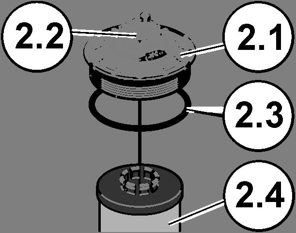


49 Performing Maintenance Changing the filter element Proceed as follows to replace the filter element: LVU-CD-10 en(us) Page 49 / 68


 of the filter and coalescing")

 and filter element (2.")
50 Performing Maintenance 1. Vent the filter and coalescing casing by opening the breather screw (2.2) in an anti-clockwise direction. 2. Start the unit using the control for ~ 20 seconds so that the filter and coalescing casing is emptied by the pump. 3. Open the cover (2.1) of the filter and coalescing casing counterclockwise with a fork wrench (wrench size 46). 4. Remove the cover (2.1) and filter element (2.4) by lifting it up out of the filter and coalescing casing. LVU-CD-10 en(us) Page 50 / 68


. Remove the")
 from the cover.")
 and")


51 Performing Maintenance 5. Pull the filter element (2.4) off the cover (2.1). Remove the O-ring (2.3) from the cover. 6. Dispose of the used filter element (2.4) and the O-ring (2.3) in an environmentally correct manner. 7. Clean the cover (2.1) and the inside of the filter and coalescing casing with a lint-free cloth. LVU-CD-10 en(us) Page 51 / 68


 into the filter and")

 of the filter and coalescing")
52 Performing Maintenance 8. Mount the O-ring (2.3) from the scope of delivery of the new filter element onto the cover (2.1). Clip the new filter element (2.4) onto the cover (2.1). 9. Lightly wet the O-ring (2.3) with medium. Place the cover (2.1) and filter element (2.4) into the filter and coalescing casing and turn this clockwise by hand. 10. Tighten the cover (2.1) of the filter and coalescing casing using a fork wrench (size 46) in a clockwise direction with 50 Nm. LVU-CD-10 en(us) Page 52 / 68
53 Performing Maintenance 11. Tighten the breather screw (2.2) in a clockwise direction. 12. The filter element change is now complete. LVU-CD-10 en(us) Page 53 / 68
54 Errors and troubleshooting Errors and troubleshooting The following errors could have different causes. The following provides information on which remedial measures are required. To reset the error message on the control, switch off the unit at the main switch for at least three seconds. Error Cause(s) Remedy LED is dark = LED is off No power supply. Check the feed-line and plug. LED flashing The main switch is switched off but the power supply is on The main switch is switched on, during operation there was a drop in voltage => restart protection. Check the main switch. Switch off the unit at the main switch for 3 seconds. LED lights up The main switch is on, but the unit is not running. Contact HYDAC. LED flashing LED flashing Electric motor / pump is not running Interval control is active. Only with control type: "Premium". Check the interval settings. LVU-CD-10 en(us) Page 54 / 68
55 Errors and troubleshooting Error Cause(s) Remedy No flow The is no power at the electric motor. The mains voltage or frequency do not correspond to the specifications on the unit. The unit is switched off at the main switch. The suction hose is kinked or faulty or a shut-off device is closed. There is air in the suction line and the pump. The viscosity of the fluid is too high. The is no power to the electric motor. The electric motor / pump is defective. The transport seals have not been removed. The pressure loss in the suction line is too great. The power outlet used is free of voltage. The mains connector is not plugged in. Plug in the power plug. Inspect the unit supply line for damage. If the unit supply line is defective, replace it immediately. Use a unit that is suitable for the mains voltage. Switch on the unit at the main switch. Check the suction hose for flow. Replace it if necessary. Fill the pump via the suction hose / hose coupling. Check the viscosity of the fluid. Heat the fluid to achieve the permissible viscosity. Check the supply line to the filtration unit. Replace it if necessary. Contact HYDAC. Remove the transport seals. Transport seals are the yellow plastic plugs. Ensure that the pressure at the inlet is within the permitted range. LVU-CD-10 en(us) Page 55 / 68
56 Errors and troubleshooting Error Cause(s) Remedy Filter contaminated (The clogging indicator appears) Collecting pan too full. The suction hose is not suitable for negative pressure. The fluid is heavily contaminated. The contamination retention capacity of the filter element has been reached. The viscosity of the fluid is too high. The suction line at the inlet is generating too much loss of pressure. Leakage on the unit / filter housing Wrong, missing, or defective sealing ring. Use a hose that is resistant to negative pressure. Replace the filter element. Check the viscosity of the fluid. Heat the fluid to achieve the permissible viscosity. Ensure that the pressure at the inlet is within the permitted range. Empty the collecting pan and eliminate the leak on the unit. Check the sealing ring on the filter element. Replace it if necessary. The cover on the filter and coalescing casing is not tight enough. Tighten the cover on the filter and coalescing casing by hand. The water drainage valve has a malfunction. The water drainage valve jams. The fluid is dewatered. Contact HYDAC. No remedy required. blinks Error message from filter and coalescing casing. Contact HYDAC. LVU-CD-10 en(us) Page 56 / 68
57 Customer Service Customer Service Regular inspection and maintenance work is indispensable for ensuring trouble-free operation and long service life for your unit. HYDAC SERVICE GMBH Friedrichsthaler Str. 15A, Werk Neunkirchen-Heinitz Germany Telephone: +49 (0) Fax: +49 (0) LVU-CD-10 en(us) Page 57 / 68
58 Taking the unit out of operation Taking the unit out of operation Drain the unit completely, including all of its components, before decommissioning. Pull out the power plug and fasten the hoses and power cord on the unit. Shutting down the unit See chapter "Taking the unit out of operation". Disposing of the unit Dispose of the packaging material in an environmentally friendly manner. After dismantling the unit and separating the various materials, dispose of the unit in an environmentally-friendly manner. LVU-CD-10 en(us) Page 58 / 68


59 Spare parts Spare parts The following spare parts may be ordered for the unit. Overview of spare parts LVU-CD-10 en(us) Page 59 / 68
60 Spare parts Spare parts list Item Qty. Part no. Designation Cover Vent screw Inspections glass Seal kit for filter and coalescing casing Clogging indicator, visual Contamination switch, electrical Water collection canister 5 liter Hose Collecting pan float switch 10 1 * Motor/pump assembly Standard control type Premium control type Filter element, 5 µm N7ON-DC005-CA61H Filter element, 10 µm N7ON-DC010-CA61H Filter element, 30 µm N7ON-DC030-CA61H *) available on request LVU-CD-10 en(us) Page 60 / 68
61 Technical details Technical details Dewatering performance Water separation efficiency > 95% acc. to ISO CD Achievable water content Dewatering rate <200 ppm 12 l/h at 5% water in the diesel Hydraulic data Operating limit Maximum flow rate Pump type Operating pressure Permissible suction pressure at suction port. Permissible pressure at pressure port connection Permissible pressure at the water drain Connection (suction and pressure side) Water drain Maximum 10% free water 10 l/min Gear pump Maximum 3 bar bar 3 bar 0 bar M26x1.5 (18L) external thread Hose Ø 10mm Water collecting tank volume 5 liter Permitted fluid temperature range 5 50 C or at least 10 C below the flash point of the fluid used/deployed. Electrical data Power supply Power consumption See motor type plate 370 W Protection class IP 54 Connector cable, length 0.5 m with safety plug LVU-CD-10 en(us) Page 61 / 68
62 Technical details General data Dimensions Material / substance Frame Filter and coalescing housing Seals Permitted ambient temperature range Empty weight 300 x 550 x 816 mm Lacquered steel Aluminum HNBR / FKM 5 50 C or at least 10 C below the flash point of the fluid used/deployed. 38 kg LVU-CD-10 en(us) Page 62 / 68
63 Model Code Model Code LVU - C D-10 - G M- 2 S E - 1 / - Type LVU = LowViscosity Unit Function C = Filtering and coalescing Operating fluid D = Diesel Nominal flow rate 10 = 10 l/min Pump version G = Gear pump Supply voltage L = 115 V AC, 60 Hz, 1 Ph E = 220 V AC, 50 Hz, 1 Ph M = 230 V AC, 50 Hz, 1 Ph F = 240 V AC, 50 Hz, 1 Ph X = others on request Water drain 1 = Manual 2 = Automatic Control type E = Eco - with On/Off switch including motor protection - visual clogging indicator S = Standard - with On/Off switch including motor protection - visual clogging indicator P = Premium - with on/off switch inc. motor protection - programmable operating times - electrical clogging indicator / automatic shut-down if filter element contaminated Clogging indicator E = Clogging indicator, visual C = Differential pressure switch, electrical (only in connection with Premium control type) Type code 1 = (You always receive the latest type) Additional - = without LVU-CD-10 en(us) Page 63 / 68

64 EC declaration of conformity EC declaration of conformity HYDAC FILTER SYSTEMS GMBH Postfach Sulzbach / Saar Germany Industriegebiet Sulzbach / Saar Germany Telefon: ++49 (0) Internet: EC declaration of conformity We hereby declare that the following designated product, on the basis of its design and construction, and in the version which we have brought to market, corresponds to the fundamental safety and health requirements contained in the directives and standards listed below. Any modification of this product that is not coordinated with us in writing will cause this declaration to lose its validity. Designation Filtration unit Type LVU CD series Part no. - Serial-no. - EU-Machinery Directive 2006/42/EC article 1 a) Dr. Andreas Schunk Date Name (CE official) Executive director: Documentation Representative: Mathias Dieter, Dipl.Kfm. Wolfgang Haering Günter Harge Registered seat of company: Sulzbach / Saar - Germany c/o HYDAC International GmbH, Industriegebiet, Sulzbach / Saar Registry Court: Saarbrücken, HRB Telephone: +49 (0) Value added tax identification number: DE Fax: +49 (0) Tax number : 040/110/ Huenter.harge@hydac.com LVU-CD-10 en(us) Page 64 / 68
65 Index Index A ambient temperature... 19, 62 Auxiliary personnel C care... 2, 6 Cause CE official Changing the filter element... 44, 49 Clogging indicator...23, 25, 28, 36, 60, 63 collecting pan... 38, 40, 56 connecting... 31, 32, 33 Connection Control... 21, 23, 25, 63 D Date Density Description... 18, 19, 41 dewatering Dewatering Dewatering performance Dewatering rate Differential pressure Dimensions Disposal Documentation Representative... 2, 64 DRAIN E EC declaration of conformity Electrical data Empty weight... 19, 62 emptying... 44, 46 Error... 40, 54, 56 Error message... 40, 56 F Filter...12, 23, 25, 27, 28, 56, 60, 62 Filter element... 27, 60 filtration...18, 20, 32, 34, 55 Filtration Float switch... 23, 25 Flow rate... 19, 32 G Gear pump...61, 63 H Hazard symbol... 8 Hydraulic data Hydraulic diagram I Imprint... 2 IN 28, 30, 33 Inlet...28, 30 INLET...23, 25 Inspection...23, 25 Internal pipe diameter IP 61 ISO...11, 61 M Main switch...37, 39 Maintenance...1, 20, 21, 44 Maintenance interval Maintenance intervals Measures Model code Motor protection switch...37, 39 Motor pump assembly...23, 25, 28 O Off switch offline filtration...11, 26 operating..6, 7, 8, 11, 12, 13, 14, 30, 37, 38, 39, 40, 41, 42, 43, 63 Operating elements Operation...12, 20, 21 Operations control OUT...28, 30, 33 Outlet...28, 30 OUTLET...23, 25 Overview P Power consumption...19, 61 Pressure differential Proper/Designated Use Protection class LVU-CD-10 en(us) Page 65 / 68
66 Index Publisher... 2 Pump... 61, 63 R Remedy repairs S select... 7 Serial-no Service setting... 37, 38, 39, 42 Signal word signal words Spare parts... 59, 60 Spare parts list Specialist personnel storing Supply voltage...38, 40, 63 switching on T Time Transport...13, 55 transporting troubleshooting...13, 38, 42, 54 W Weight LVU-CD-10 en(us) Page 66 / 68
67
68 HYDAC FILTER SYSTEMS GMBH Industriegebiet Postfach Sulzbach/Saar Sulzbach/Saar Germany Germany Phone: +49 (0) Central Fax: +49 (0) (Technical Department) Fax: +49 (0) Sales Department Internet:
Court of Registration: Saarbrücken, HRB Haering
 LVU-CD-10 LowViscosity Unit CoaleserDiesel with control type: Eco Operating and Maintenance Instructions English (translation of original instructions) Document No.: 4067271 Keep for future reference.
WBF /-T003 bar magnet insert for Wombat filter housing
 WBF /-T003 bar magnet insert for Wombat filter housing Installation and Maintenance Instructions English (translation of original instructions) Document No.: 4332365 Imprint Imprint Manufacturer / publisher
LVU-CD-40 LowViscosity Unit CoalescerDiesel
 LVU-CD-40 LowViscosity Unit CoalescerDiesel Operating and Maintenance Instructions English (translation of original instructions) Document No.: 4035823a Keep for future reference. Imprint Imprint Publisher
Filtromat OF5LxxPxMxB
 Filtromat Operating and Maintenance Instructions English (translation of original instructions) Document No.: 3594726a Trademarks Trademarks The trademarks of other companies designate the products of
MRF D3 MultiRheo Filter
 MRF D3 MultiRheo Filter Operating and Maintenance Instructions English (translation of original instructions) Document no.: 3217120b Imprint Imprint Publisher and responsible for the content: HYDAC FILTER
VarnishElimination Unit- Filtration VEU-F-60/1-x-C
 VarnishElimination Unit- Filtration VEU-F-60/1-x-C Operating and Maintenance Instructions English (translation of original instructions) Keep for future reference. Document No.: 4104528 Imprint Imprint
CSM 1000 Series. ContaminationSensor Module. Operating and Maintenance Instructions. English (translation of original instructions)
") ContaminationSensor Module Operating and Maintenance Instructions English (translation of original instructions) Documentation no.: 3265074g (from series no. 4555/2009) Trademarks Trademarks The trademarks
ContaminationSensor Module Operating and Maintenance Instructions English (translation of original instructions) Documentation no.: 3265074g (from series no. 4555/2009) Trademarks Trademarks The trademarks
FMM-P-L. FluidMonitoring Module. Installation and Maintenance Instructions. English (translation of original instructions) Document No.
 Document No.") FMM-P-L Installation and Maintenance Instructions English (translation of original instructions) Document No.: 3493215 Trademarks Trademarks The trademarks of other companies are exclusively used for the
FMM-P-L Installation and Maintenance Instructions English (translation of original instructions) Document No.: 3493215 Trademarks Trademarks The trademarks of other companies are exclusively used for the
Spare parts list Return line filter RFM with 2-hole attachment
 Spare parts list Return line filter with 2-hole attachment Tank-top mounted version: up to 200 l/min, up to 10 bar 75 90 150 165 185 195 1. MAINTENANCE 1.1 GENERAL Please follow the maintenance instructions!
Spare Parts List Return line filter RF
 Spare Parts List Return line filter up to 15000 l/min, up to 25 bar 30 60 110 160 240 330 450 580 660 950 1300 2500 4000 5200 6500-7800 15000 1. MAINTENANCE 1.1 GENERAL Please follow the maintenance instructions!
Spare Parts List Filter NFD Change-Over Version
 Spare Parts List Filter Change-Over Version up to 1600 l/min, up to 5 bar 1340 640 540 7840 10440 1. MAINTENANCE GENERAL Please follow the maintenance instructions! 1. INSTALLATION Before fitting the filter
Swing Piston Compressors and Vacuum Pumps
 Swing Piston Compressors and Vacuum Pumps NPK 018 AC Pressure NPK 018 DC Pressure NPK 018 AC Vacuum NPK 018 DC Vacuum Operating and Installation Instructions Read and observe these Operating and Installation
Spare Parts List Tank-Top Return Line Filter RFN with Elements to DIN up to 630 l/min, up to 10 bar
 Spare Parts List Tank-Top Return Line Filter RFN with Elements to DIN 24550 up to 630 l/min, up to 10 bar RFN 40 RFN 63 RFN 100 RFN 160 RFN 250 RFN 400 RFN 630 1. MAINTENANCE 1.1 GENERAL Please follow
Pressure relief valve
 Pressure relief valve Operating manual Series DHV 712 Version BA-2015.10.20 EN Print-No. 300 510 TR MA DE Rev001 ASV Stübbe GmbH & Co. KG Hollwieser Straße 5 32602 Vlotho Germany Phone: +49 (0) 5733-799-0
Spare Parts List Return Line Filter RFM with 4-hole attachment
 Spare Parts List Return Line Filter with 4-hole attachment Tank-top mounted version: up to 850 l/min, up to 10 bar 75 90 150 165 185 195 210 270 330 500 600 661 851 1. MAINTENANCE GENERAL Please follow
Installation and Operating Manual for Tank and Equipment Cleaning Nozzles Series 5TM
 Installation and Operating Manual for Tank and Equipment Cleaning Nozzles Series 5TM 150 150 150 This instruction manual contains proprietary information which is protected by copyright laws. No part of
Oil-free piston compressors KK and piston vacuum pumps KV
 Oil-free piston compressors KK and piston vacuum pumps KV Installation and Operating Instructions 0678106030L02 1707V003 Contents Important information 1 About this document 2 1.1 Warnings and symbols
User Guide. Lubricus Lubrication System LUB-D1/LUB-D2/LUB-D3/LUB-D4 (24 VDC)
") User Guide Lubricus Lubrication System LUB-D1/LUB-D2/LUB-D3/LUB-D4 (24 VDC) version 04/2013 Content General Information 3 Warning 3 Scope of Supply 3 Overview 3 General safety details 4 Intended use 4
User Guide Lubricus Lubrication System LUB-D1/LUB-D2/LUB-D3/LUB-D4 (24 VDC) version 04/2013 Content General Information 3 Warning 3 Scope of Supply 3 Overview 3 General safety details 4 Intended use 4
Assembly and Maintenance Manual Type ASNU
 Assembly and Maintenance Manual Type ASNU Hatschekstr.36 69126 Heidelberg Germany Tel +49(0)6221 30470 Fax +49(0)6221 304731 info@stieber.de www.stieber.de Date of issue: 30.05.2018 GB Revision: 0 U:\EngUsers\!ProduktDoku\1AAA_Einbauerklaerung_Wartungsanleitung_Konformitaetserklaerung\1AAA_Wartungsanleitungen\Orginal_Worddatei\_ASNU.docx
Type 6213 EV, 6281 EV
 Type 6213 EV, 6281 EV 2/2-way solenoid valve 2/2-Wege-Magnetventil Électrovanne 2/2 voies Operating Instructions Bedienungsanleitung Manuel d utilisation 1 OPERATING INSTRUCTIONS The operating instructions
Application cup for OptiFlex 2 GM03 manual powder gun
 En Operating instructions and spare parts list Application cup for OptiFlex 2 GM03 manual powder gun Translation of the original operating instructions Documentation OptiFlex GM03 application cup Copyright
Type Operating Instructions. Bedienungsanleitung Manuel d utilisation. 2/2-way solenoid valve 2/2-Wege-Magnetventil Électrovanne 2/2 voies
 Type 5404 2/2-way solenoid valve 2/2-Wege-Magnetventil Électrovanne 2/2 voies Operating Instructions Bedienungsanleitung Manuel d utilisation Contents 1 Operating instructions...2 2 Intended use...3 3
Assembly and Maintenance Manual Type AS
 Assembly and Maintenance Manual Type AS Hatschekstr.36 69126 Heidelberg Germany Tel +49(0)6221 30470 Fax +49(0)6221 304731 info@stieber.de www.stieber.de Date of issue: 30.05.2018 GB Revision: 0 U:\EngUsers\!ProduktDoku\1AAA_Einbauerklaerung_Wartungsanleitung_Konformitaetserklaerung\1AAA_Wartungsanleitungen\Orginal_Worddatei\_AS.docx
Type Operating Instructions. Bedienungsanleitung Manuel d utilisation. 2/2-Way Solenoid Valve 2/2-Wege-Magnetventil Électrovanne à 2/2 voies
 Type 5282 2/2-Way Solenoid Valve 2/2-Wege-Magnetventil Électrovanne à 2/2 voies Operating Instructions Bedienungsanleitung Manuel d utilisation 1 OPERATING INSTRUCTIONS The operating instructions contain
Spare parts list Inline filter FLND switchable
 Spare parts list Inline filter switchable to DIN 24550*, up to 400 l/min, up to 63 bar *Filters and fi lter elements also available in HYDAC dimensions 60 110 140 40 63 100 160 250 400 1. MAINTENANCE 1.1
Type 0283, Operating Instructions. Bedienungsanleitung Manuel d utilisation. 2/2-way solenoid valve 2/2-Wege-Magnetventil Électrovanne 2/2 voies
 Type 0283, 0293 2/2-way solenoid valve 2/2-Wege-Magnetventil Électrovanne 2/2 voies Operating Instructions Bedienungsanleitung Manuel d utilisation Contents 1 The operating instructions...2 2 Intended
General operating manual for assembly, commissioning and maintenance of valves and hydraulic manifolds
 for assembly, commissioning and maintenance of valves and hydraulic manifolds 110210_general_operating_manual 07.2018 Table of contents Contents Page Important information 2 Important safety instructions
MV Series Motors Operation & Parts Manual
 MV Series Motors Operation & Parts Manual Models M3V, M5V, M5V-US For use with M3V s/n 101057 & below, M3V-UK s/n 103013 & below, M5V & M5V-US s/n 102972 & below. EU Declaration of Conformity Finish Thompson
Installation, Operating & Maintenance Instructions. All-metal gate valve with compact or extended pneumatic actuator
 Installation, Operating & Maintenance Instructions All-metal gate valve with compact or extended pneumatic actuator Series 48 DN 16 320 mm (I.D. ⅝" 12") This manual is valid for the following product ordering
Swing Piston Compressors and Vacuum Pumps
 Swing Piston Compressors and Vacuum Pumps NPK 050 NPK 0100 Operating and Installation Instructions Read and observe these Operating and Installation Instructions! KNF Neuberger GmbH Alter Weg 3 D-79112
Type Operating Instructions. Bedienungsanleitung Manuel d utilisation. 2/2-Way Solenoid Valve 2/2-Wege-Magnetventil Électrovanne à 2/2 voies
 Type 5282 2/2-Way Solenoid Valve 2/2-Wege-Magnetventil Électrovanne à 2/2 voies Operating Instructions Bedienungsanleitung Manuel d utilisation Contents 1 Operating Instructions... 2 2 Authorized use...
Micro Diaphragm Gas Sampling Pumps
 Operating and Installation Instructions Micro Diaphragm Gas Sampling Pumps Type range: NMP 03 KP DC-B1 NMP 03 KP DC-S NMP 03 KP DC-B3 NMP 03 KP DC-M NMP 03 KP DC-L You have selected a high-quality KNF
SBS Manual for the specialised craftsman. Filling and flushing station. Connection Operation. en Manual
 SBS 2000 Filling and flushing station Manual for the specialised craftsman Connection Operation Thank you for buying this RESOL product. Please read this manual carefully to get the best performance from
Operating instructions
 Operating instructions Digital tank contents indicator DTA 10 DTA 10 DTA 10 0 4.0 m fuel oil 0 3.5 m water Read instructions before using device! Observe all safety information! Keep instructions for future
original operating manual Operating manual Translation of the Item-No.: ,
 Translation of the original operating manual Operating manual Item-No.: 015 431 551, 015 431 581 Important! Copyright The operating manual is always to be read before commissioning the equipment. No warranty
CO 3-WAY PNEUMATIC VALVE INSTRUCTION MANUAL 2080
 CO 3-WAY PNEUMATIC VALVE INSTRUCTION MANUAL 2080 STI S.r.l has taken every care in collecting and verifying the documentation contained in this Instruction Manual. The information herein contained are
Turbocharger / VTR..0, VTR..1 Original assembly instructions English
 Assembly Instructions Turbocharger / VTR..0, VTR..1 Original assembly instructions English This document is valid for the VTR..0/..1 series: VTR160, VTR200, VTR250, VTR320, VTR400 VTR161, VTR201, VTR251,
Installation, Operating & Maintenance Instructions. HV gate valve with pneumatic actuator. Series 110 DN mm (I. D.
 Installation, Operating & Maintenance Instructions HV gate valve with pneumatic actuator Series 110 DN 250 320 mm (I. D. 10" 12") This manual is valid for the following product ordering numbers: 11048-.
SUNC1200 / ITEM #40882 SUBMERSIBLE UTILITY PUMP OPERATIONS MANUAL
 SUNC1200 / ITEM #40882 SUBMERSIBLE UTILITY PUMP OPERATIONS MANUAL WWW.SUNRUNNERPOOL.COM Performance Model HP GPH of Water @ Total Feet Of Lift 0 ft. 5 ft. 10 ft. 15 ft. 20 ft. 25 ft. Max. Lift SUNC1200
OFX7 Operating Maintenance and Troubleshooting Manual L-4219
 OFX7 Operating Maintenance and Troubleshooting Manual L-4219 L-2999 Created 9.2012 User Manual OFX7 L-4219 - Table of Contents - Preface. 4 Customer Service. 4 Modifications to the Product 4 Warranty.
Operating and Installation Instructions Swing Piston Compressors and Vacuum Pumps
 Operating and Installation Instructions Swing Piston Compressors and Vacuum Pumps UNPK04DC Pressure UNPK04DCB Pressure UNPK04DC Vacuum UNPK04DCB Vacuum KNF Neuberger, Inc 2 Black Forest Rd Trenton, NJ
OWNER S MANUAL SELF-PRIMING PORTABLE UTILITY PUMP
 Model 54011-0 OWNER S MANUAL SELF-PRIMING PORTABLE UTILITY PUMP Questions, problems, missing parts? Before returning to the store call AQUAPRO Customer Service 8 a.m. - 5 p.m., EST, Monday-Friday 1-844-242-2475
Assembly and Maintenance Manual Type RSBW
 Assembly and Maintenance Manual Type RSBW Hatschekstr. 36 69126 Heidelberg Germany Tel +49(0)6221 30470 Tel +49(0)6221 304731 info@stieber.de www.stieber.de Stieber Clutch Date of issue: 16/03/2017 GB
Tension Meter. Edition FT 03.E. FT Series. Instruction Manual. Valid as of: Please keep the manual for future reference!
 Tension Meter FT Series S C H M I D T c o n t r o l i n s t r u m e n t s Edition FT 03.E Model FT Instruction Manual Valid as of: 01.09.2011 Please keep the manual for future reference! Contents 1 Warranty
User manual Pipe notcher Type: AL 1-2E
 User manual Pipe notcher Type: AL 1-2E Page 1 of 27 Table of contents 1. Foreword... 4 1.1. Name of machine... 4 1.2. Warning... 4 1.3. Target group for each chapter... 4 1.4. Symbols... 4 1.5. Re-ordering
INSTRUCTION MANUAL. I/P Converter DSG BXXY3Z DSG BXXY4Z
 INSTRUCTION MANUAL I/P Converter DSG BXXY3Z DSG BXXY4Z Revision 2.0 3.626 016136 en Page 1/15 Should you have any questions concerning the I/P converter, please contact the Service Department of the Product
Type Operating Instructions. Bedienungsanleitung Manuel d utilisation. 2/2-way solenoid valve 2/2-Wege-Magnetventil Électrovanne 2/2 voies
 Type 6027 2/2-way solenoid valve 2/2-Wege-Magnetventil Électrovanne 2/2 voies Operating Instructions Bedienungsanleitung Manuel d utilisation 1 OPERATING INSTRUCTIONS The operating instructions contain
Type Operating Instructions. Bedienungsanleitung Manuel d utilisation
 Type 0131 2/2- or 3/2-way solenoid valve 2/2- oder 3/2-Wege-Magnetventil Électrovanne 2/2 ou 3/2 voies Operating Instructions Bedienungsanleitung Manuel d utilisation 1 OPERATING INSTRUCTIONS The operating
LowViscosity Housing- Coalescer Diesel LVH-CD
 LowViscosity Housing- Coalescer Diesel LVH-CD Description The LowViscosity Housing Coalescer LVH-C is mainly used for the dewatering of diesel. It is especially suitable for applications with large amounts
Spin-on filter according to Bosch Rexroth standard: Type 50 SL 30 to 80D. Features. Contents. RE Edition:
 Spin-on filter according to Bosch Rexroth standard: Type 50 SL 30 to 80D RE 51476 Edition: 2015-06 Nominal sizes: 30 to 80D Connection up to G1; SAE 10 56558_d Features Spin-on filters are used in hydraulic
Operating manual. Custom made gearboxes
 Operating manual Custom made gearboxes DSS-Nr. 100389549 DSS-Rev. 001 Datum 16.01.2018 Contents Contents 1 General information 3 1.1 Using the operating manual 3 1.2 Warnings in this operating manual 4
HST-BL-2830MS & HST-BL-2830MS-USA
 HST-BL-2830MS & HST-BL-2830MS-USA Release date: 02/2017 High - System - Technik Im Martelacker 12 D-79588 Efringen-Kirchen Phone 0 76 28-91 11-0 Fax 0 76 28-91 11-90 E-Mail: info@hs-technik.com Web: www.hs-technik.com
Angle seat valve with piston actuator VZXA-...-K
 Angle seat valve with piston actuator VZXA-...-K Festo AG & Co. KG Postfach 73726 Esslingen Germany +49 711 347-0 www.festo.com 3 Further information Accessories www.festo.com/catalogue Spare parts www.festo.com/spareparts
TBP SERIES PUMPS OPERATION & PARTS MANUAL
 TBP SERIES PUMPS OPERATION & PARTS MANUAL EU Declaration of Conformity Finish Thompson Inc. hereby declares that the following machine(s) fully comply with the applicable health and safety requirements
Installation and Operating Instructions Magnetic Vibrator MR 1
 Installation and Operating Instructions Magnetic Vibrator MR 1 (Translation of the Original Instruction Manual) Würges Vibrationstechnik GmbH Daimlerstraße 9 D-86356 Neusäß Telephone +49 821 999824-00
Installation and Operation Manual
 Industrial Process Installation and Operation Manual Advantage Actuator 2.0 Table of Contents Table of Contents Introduction and Safety...2 Safety message levels...2 User health and safety...2 Transportation
Wilo-Control SC-Fire Jockey
 Pioneering for You Wilo-Control SC-Fire Jockey de en fr Einbau- und Betriebsanleitung Installation and operating instructions Notice de montage et de mise en service nl Inbouw- en bedieningsvoorschriften
Angle seat valve with piston actuator VZXA-...-K
 Angle seat valve with piston actuator VZXA-...-K Instructions Operating (Translation of the original instructions) Festo AG & Co. KG Ruiter Straße 82 73734 Esslingen Germany +49 711 347-0 www.festo.com
Installation, Operating & Maintenance Instructions. UHV gate valve with pneumatic actuator. Series 108 DN mm (I. D. 2½ 8 )
") Installation, Operating & Maintenance Instructions UHV gate valve with pneumatic actuator Series 108 DN 63 200 mm (I. D. 2½ 8 ) This manual is valid for the following product ordering numbers: 108.. -.
Installation, Operating & Maintenance Instructions UHV gate valve with pneumatic actuator Series 108 DN 63 200 mm (I. D. 2½ 8 ) This manual is valid for the following product ordering numbers: 108.. -.
RESOL SBS 1000 * * Connection Operation
 RESOL SBS 1000 Connection Operation FlowCon SBS 1000 A www.resol.de *48003820* 48003820 Thank you for buying this RESOL product. Please read this manual carefully to get the best performance from this
Operating manual. original operating manual. HDA eco Box 12/24V DC Automatic Dispenser. Translation of the. Item No.:
 Operating manual HDA eco Box 12/24V DC Automatic Dispenser Item No.: 110 500 900 Translation of the original operating manual Important! Copyright The operating manual is always to be read before commissioning
Operating instructions Accu Jet
 Operating instructions Accu Jet Keep for future use! Ident number: 04.8800.000 Air Line Table of contents 1 Scope of delivery... 4 2 Operator instructions... 5 3 Safety... 6 3.1 Intended use...8 4 Description
Operating instructions and spare parts list. LM01 Level sensor. Translation of the original operating instructions
 En Operating instructions and spare parts list LM01 Level sensor Translation of the original operating instructions Documentation LM01 Level sensor Copyright 2005 Gema Switzerland GmbH All rights reserved.
Hydraulic Immediate Need Power Pack
 Safety, Operation, and Maintenance Manual WARNING Improper use of this tool can result in serious bodily injury This manual contains important information about product function and safety. Please read
Exchange of rollers from the XTS-Mover
 Service documentation for AT901-0050-0550 and AT9011-00x0-0550 Version: Date: 1.0 0.10.017 Table of contents Table of contents 1 Foreword... 5 1.1 Notes on the documentation... 5 1. Documentation issue
HV angle valve with single acting pneumatic actuator and closing spring (NC)
") Installation, Operating & Maintenance Instructions HV angle valve with single acting pneumatic actuator and closing spring (NC) Series 264 DN 100 160 mm (I. D. 4 6 ) This manual is valid for the following
Installation, Operating & Maintenance Instructions HV angle valve with single acting pneumatic actuator and closing spring (NC) Series 264 DN 100 160 mm (I. D. 4 6 ) This manual is valid for the following
DC Master 24/ A
 USERS MANUAL DC Master 24/12 50-60A DC-DC converter MASTERVOLT Snijdersbergweg 93, 1105 AN Amsterdam The Netherlands Tel.: +31-20-3422100 Fax.: +31-20-6971006 www.mastervolt.com ENGLISH Copyright 2015
Mobile Filter Unit MFU-15
 Mobile Filter Unit MFU-15 Description The MFU 15 MobileFiltration unit is used as a portable service unit for filling hydraulic systems, flushing small hydraulic systems as well as for cleaning in bypass
SUNC3000 / Item #40885
 SUNC3000 / Item #40885 AUTOMATIC POOL COVER PUMP OPERATIONS MANUAL WWW.SUNRUNNERPOOL.COM 1 . Performance GPH of Water @ Total Feet Of Lift MODEL HP Max. Lift 0 ft. 5 ft. 10 ft. 15 ft. 20 ft. SUNC3000 1/3
Turbocharger / TPS-H Original assembly instructions English
 Assembly Instructions Turbocharger / TPS-H Original assembly instructions English This document is valid for the TPS-H series: TPS44-H, TPS48-H, TPS52-H Purpose TPS-H turbocharger The assembly instructions
Declaration of Conformity as per Directive 97/23/EC
 Declaration of Conformity as per Directive 97/23/EC The manufacturer declares that:, 47906 Kempen, Germany PTFE-lined Rotary plug valves Series 23e, with packing with lever for 90 operation with worm gear
Rolli D6/5A. Operating Instructions HORN GMBH & CO. KG. Product Description. Safety Indications. Mounting. Commissioning.
 Declaration of Conformity Operating Instructions Rolli D6/5A 440209101-A 03/2004 Subject to technical alterations. Text and design copyrighted. Reprinting and copying, even if excerpts, only with written
Angle seat valve with diaphragm actuator VZXA-...-M
 Angle seat valve with diaphragm actuator VZXA-...-M Instructions Operating (Translation of the original instructions) Festo AG & Co. KG Ruiter Straße 82 73734 Esslingen Germany +49 711 347-0 www.festo.com
Micro Diaphragm Gas Sampling Pumps
 Operating and Installation Instructions Micro Diaphragm Gas Sampling Pumps Type range: NMP830K_DC-M HP NMP830.1.2K_DC-M HP NMP830K_DC-B HP NMP830.1.2K_DC-B HP NMP830K_DC-B4 HP NMP830.1.2K_DC-B4 HP You
Off-line filter system
 Off-line filter system 30 NFF2, 50 NFF2, 80 NFF2 RE 51433-B/04.10 Replaces: -.- English Operating instructions The data specified above only serve to describe the product. No statements concerning a certain
HST -LS Interlocking device (Translation of Original Manual)
") Installation and Operating Manual for Components HST -LS Interlocking device (Translation of Original Manual) HST-LS Ident.-No.: 10268 HST-LS Ident.-No.: 10269 HST-LS, pictured Ident-Nr. 10269 The image
Installation and Operating Manual for Components HST -LS Interlocking device (Translation of Original Manual) HST-LS Ident.-No.: 10268 HST-LS Ident.-No.: 10269 HST-LS, pictured Ident-Nr. 10269 The image
Installation manual wall-mounted distributor
 EN Installation manual wall-mounted distributor EN 60003233 Issue 11.2016 2016-14-11 Table of contents 1 About this manual 3 1.1 Structure of the warnings 3 1.2 Symbols used 4 1.3 Signal words used 4 2
Operating Instructions K Always on the safe side.
 Operating Instructions K9 4953. Always on the safe side. KaVo Dental GmbH Wangener Straße 78 D-88299 Leutkirch Tel.: 0 75 61 / 86-150 Fax: 0 75 61 / 86-265 A 1 User information...2 A 1.1 Meaning of the
Turbocharger / A100-L Original assembly instructions English
 Assembly Instructions Turbocharger / A100-L Original assembly instructions English This document is valid for the A100-L series: A165-L, A170-L, A175-L, A180-L, A185-L, A190-L Purpose The assembly instructions
Installation manual portable distributors
 EN Installation manual portable distributors EN 60003206 Issue 11.2016 15/11/2016 Table of contents 1 About this manual 3 1.1 Structure of the warnings 3 1.2 Symbols used 4 1.3 Signal words used 4 2 Intended
Hydraulic PTO Flow Device
 Safety, Operation, and Maintenance Manual WARNING Improper use of this tool can result in serious bodily injury This manual contains important information about product function and safety. Please read
Operating instructions ErgoPack 600 E
 Operating instructions ErgoPack 600 E Operation of the device is only permitted if the operating instructions have been carefully read and understood before use! Declaration of conformity EU declaration
OWNER S MANUAL SUBMERSIBLE UTILITY PUMP
 Model 51101-0 OWNER S MANUAL SUBMERSIBLE UTILITY PUMP Questions, problems, missing parts? Before returning to the store call AQUAPRO Customer Service 8 a.m. - 5 p.m., EST, Monday-Friday 1-844-242-2475
MANUAL. Single charger
 MANUAL Single charger HST-PR-2830 & HST-PR-2830USA for HS-Technik batteries HST-PR-18xx HST-PR-14xx issue date: November 2016 Table of contents Page 1. Basic information...3 1.1. Purpose of this document...3
Drive Unit e-drive1. Installation instructions 04/2014. English translation of the original German installation instructions
 Drive Unit e-drive1 Installation instructions 04/2014 English translation of the original German installation instructions Contents Foreword... 3 Availability... 3 Structural features in the text... 3
Mounting and Operating Instructions EB 8039 EN. Type 3351 Pneumatic On/off Valve. Type 3351 Pneumatic On/off Valve. Type 3351 Pneumatic On/off Valve
 Type 3351 Pneumatic On/off Valve Type 3351 Pneumatic On/off Valve Type 3351 Pneumatic On/off Valve Version with handwheel Mounting and Operating Instructions EB 8039 EN Edition May 2016 Definition of signal
Type 5411, Operating Instructions. Bedienungsanleitung Manuel d utilisation
 Type 5411, 5413 3/2 or 4/2 way solenoid valve 3/2 oder 4/2-Wege-Magnetventil Électrovanne 3/2 ou 4/2 voies Operating Instructions Bedienungsanleitung Manuel d utilisation 1 THE OPERATING INSTRUCTIONS The
Installation, Operating & Maintenance Instructions. HV angle valve with pneumatic actuator single acting with closing spring (NC)
") Installation, Operating & Maintenance Instructions HV angle valve with pneumatic actuator single acting with closing spring (NC) Series 264 DN 10 50 mm (I. D. ⅜" 2") HV inline valve with pneumatic actuator
Installation, Operating & Maintenance Instructions HV angle valve with pneumatic actuator single acting with closing spring (NC) Series 264 DN 10 50 mm (I. D. ⅜" 2") HV inline valve with pneumatic actuator
Battery Charger. Series EASY Charger. User s manual
 Battery Charger Series EASY Charger User s manual 1 Warranty RIPEnergy is not manufacturer of these units. All technical information s, data s and dimensions rely on information s given by the manufacturer.
Operating manual Separator
 Operating manual Separator Sheet no. AS/4.1.141.1.1 issue 20.08.2014 Contents Section Title Page 0 Introduction... 1 1 Intended use......1 2 Marking of the fitting... 1 3 Safety instructions... 2 4 Transport
EPS 16 ATEX 1072 X, IECEx EPS X. Operating Instructions. Solenoid coil Type AC19 Magnetspule Typ AC19 Bobine magnétique Type AC19
 , IECEx EPS 16.0030X Solenoid coil Type AC19 Magnetspule Typ AC19 Bobine magnétique Type AC19 Device with II 2G/D Ex approval Geräte mit II 2G/D Ex Zulassung Appareils avec mode de protection II 2G/D Ex
EF SERIES MOTORS OPERATION & PARTS MANUAL
 EF SERIES MOTORS OPERATION & PARTS MANUAL Models S1, S2, S3, S4 S1, S2, S3 S4 EU Declaration of Conformity Finish Thompson Inc. hereby declares that the following motors fully comply with the applicable
SPARK PLUG CLEANING KIT OPERATING MANUAL
 SPARK PLUG CLEANING KIT OPERATING MANUAL Spark Plugs - Tools & Accessories P/N 01.20.002 Rev. 08/2015 Copyright Copyright 2015 MOTORTECH GmbH. All rights reserved. Distribution and reproduction of this
MANN+HUMMEL ENTARON XD. Installation and Maintenance Manual. Version 0709
 MANN+HUMMEL ENTARON XD Installation and Maintenance Manual Version 0709 Contact information This installation and maintenance manual is a component part of the scope of delivery. It must be kept in a safe
ZE motor-protective relay Overload monitoring of EEx e motors
 Building Automation Industrial Automation Systems Hardware and Engineering ZE motor-protective relay Overload monitoring of EEx e motors 0/0 AWB300-5GB A Think future. Switch to green. All brand and product
GENERAL WARNING. General instructions. Technical assistance. Doseuro S.r.l. Liability
 Diaphragm interposed fluid head Use and maintenance manual Model Model BR Model UK Positive displacement metering pump PDP Series Type B I 250 I 350 SD GENERAL WARNING General instructions We thank you
Starting up hydraulic systems
 General / Installation A hydraulic system that operates economically, safely, and trouble-free requires careful planning, as well as proper installation and start-up. Conscientious maintenance has a considerable
Translation of the Original operating instructions Lifting device Z 70 /...
 Translation of the Original operating instructions Lifting device Z 70 /... Content 1. Lifting device / Correct use according to regulations 2. Basic principles 3. General information 4. Special remarks
Adjustable Speaker Mount GRAVIS 12
 Adjustable Speaker Mount GRAVIS 12 User's Manual Translation of the original instructions Version 3.3 Released: 19.01.2017 Important Information, Please Read Before Use! KLING & FREITAG GmbH Junkersstraße
Installation, Operation, and Maintenance Manual
 Industrial Process Installation, Operation, and Maintenance Manual Cam-Tite Ball Valve Table of Contents Table of Contents Introduction and Safety...2 Safety message levels...2 User health and safety...2