Dismounting. Removing seals Removing non-contact seals Removing contact seals
|
|
|
- Carol Reed
- 5 years ago
- Views:
Transcription
1
2 Dismounting Dismounting rolling bearings What to remember Preparations prior to dismounting Appropriate dismounting methods Dismounting a bearing fitted on a cylindrical shaft seat Manual dismounting Dismounting with a hydraulically-assisted puller Dismounting using the oil injection method Dismounting with a press Dismounting with heat Dismounting a bearing fitted on a tapered shaft seat Manual dismounting Dismounting with a hydraulically-assisted puller Dismounting using the oil injection method Dismounting a bearing fitted on an adapter sleeve Manual dismounting: plain shafts Manual dismounting: stepped shafts. 262 Dismounting with a hydraulic nut Dismounting using the oil injection method Dismounting a bearing fitted on a withdrawal sleeve Manual dismounting Dismounting with a hydraulic nut Dismounting using the oil injection method Dismounting a bearing from a solid housing Manual dismounting Dismounting using the oil injection method Dismounting with heat Dismounting a bearing from a shaft and a solid housing simultaneously Dismounting bearing units What to remember Preparations prior to dismounting Dismounting ball bearing units with grub (set) screw locking Dismounting ball bearing units with an eccentric locking collar Dismounting ball bearing units fitted on an adapter sleeve Dismounting SKF ConCentra ball bearing units Dismounting SKF ConCentra roller bearing units Dismounting roller bearing units with a cylindrical locking collar Dismounting bearing housings What to remember Preparations prior to dismounting Dismounting split plummer (pillow) block housings Dismounting flanged housings Removing seals Removing non-contact seals Removing contact seals
3 Dismounting Dismounting rolling bearings What to remember When dismounting, there is always the potential to damage an otherwise good bearing. Therefore, whenever possible, do not dismount an undamaged bearing. However, if you must do so and intend to reuse the bearing after dismounting, remember the following: Do not hit the bearing rings or any other part directly. Never allow the dismounting force to be transmitted through the rolling elements. Do not heat the bearing with an open flame. The tools and methods used to dismount rolling bearings often depend on the size of the bearing. Generally, bearings can be categorized as: small bearings: bore diameter d 80 mm medium-size bearings: bore diameter 80 mm < d < 200 mm large bearings: bore diameter d 200 mm After a bearing has been dismounted, wash it with a suitable cleaning solvent and dry it carefully. Inspect all bearing parts, especially the raceways, rolling elements and cage for wear or damage. If the bearing can be reused, protect it against corrosion by coating it thoroughly with either grease, oil or an anti-corrosive fluid, and repackage it. Small sealed bearings and bearings that are very dirty or encrusted with oxidized lubricant are generally not worth cleaning. Normally, it is more economical to scrap the old bearing and replace it with a new one. NOTE: Mark the relative position of the bearing in the housing (or on the shaft) ( fig. 1) before the bearing is dismounted. When an undamaged bearing is remounted, the non-rotating ring is typically turned by 120 to 180 to enable a new part of the raceway to be in the load zone. Dismounting tools and products are available from SKF Maintenance Products ( Appendix 0, starting on page 435). The SKF Dismounting fluid is suitable for use when dismounting with hydraulicallyassisted tools and when using the oil injection method. For additional information, visit The SKF Reliability Maintenance Institute (RMI) offers a comprehensive range of training courses in dismounting techniques ( Training, starting on page 326). Contact your local SKF representative for additional information, or visit Preparations prior to dismounting Taking the time to prepare can make dismounting easier. If available, review the assembly drawing(s) and study the bearing arrangement. Then, before starting any work, observe the following guidelines: Clean the application and the surrounding area thoroughly. Have suitable containers on hand to retrieve lubricant samples and collect the used lubricant. Have a suitable cleaning solvent available, e.g. petroleum, kerosene or a strong alkaline solution, to clean the shaft, housing, and bearing if it is to be reused. NOTE: Due to environmental considerations, SKF does not recommend the use of chlorinated solvents of any kind. 254
4 Dismounting rolling bearings Appropriate dismounting methods SKF recommends using any one of the following methods to dismount bearings: Fig. 1 manual dismounting dismounting with hydraulically-assisted tools dismounting using the oil injection method dismounting with heat The method used depends largely on the size and type of bearing. Small bearings can be removed from their seats with mechanical tools. Larger bearings generally require greater force than a mechanical tool can provide. Therefore, SKF recommends either hydraulically-assisted tools or the oil injection method, or both. Heating rings or special induction heaters can be used to remove inner rings of needle roller bearings or NU, NJ and NUP design cylindrical roller bearings. However, using heat to remove other bearing types should only be done as a last resort. To use the oil injection method, it is presupposed that the necessary oil supply duct and distribution groove have been designed into the bearing arrangement ( Appendix G, page 405)
5 Dismounting Dismounting a bearing fitted on a cylindrical shaft seat Manual dismounting Whenever possible, support the shaft in a suitable bench vice ( fig. 2) to avoid damaging the shaft or bearing during the dismounting process. Small bearings can be removed from the shaft with a mechanical puller. The claws must be applied to the inner ring or an adjacent component, e.g. a labyrinth ( fig. 3). If it is not possible to apply the claws to the inner ring or a suitable adjacent component, withdraw the bearing via the outer ring. To avoid damage during dismounting, SKF recommends turning the outer ring while the bearing is being dismounted ( fig. 4). However, when this technique is used, SKF does not recommend reusing the bearing. Fig. 2 Fig. 3 Fig
. Be careful when using this technique, because it is very easy to damage the shaft.")
6 Dismounting rolling bearings If a suitable puller is not available, a hammer and a soft metal drift punch or similar tool can be used to drive the bearing from its seat. Light taps with a hammer should be applied evenly around the whole side face of the inner ring ( fig. 5). Be careful when using this technique, because it is very easy to damage the shaft. Also, SKF does not recommend reusing the bearing as undetectable damage may have been done to the bearing during the dismounting process. Fig. 5 Dismounting with a hydraulically-assisted puller The force to dismount bearings that are mounted with an interference fit on the shaft increases rapidly with the size of the bearing. Therefore, SKF recommends using a hydraulically-assisted heavy-duty puller ( fig. 6) when dismounting large bearings. These pullers are typically available for bearings with an outside diameter up to 500 mm. When using these, follow the instructions supplied with the puller. SKF also offers hydraulically assisted puller sets that can be used to dismount small and medium-size bearings. Fig
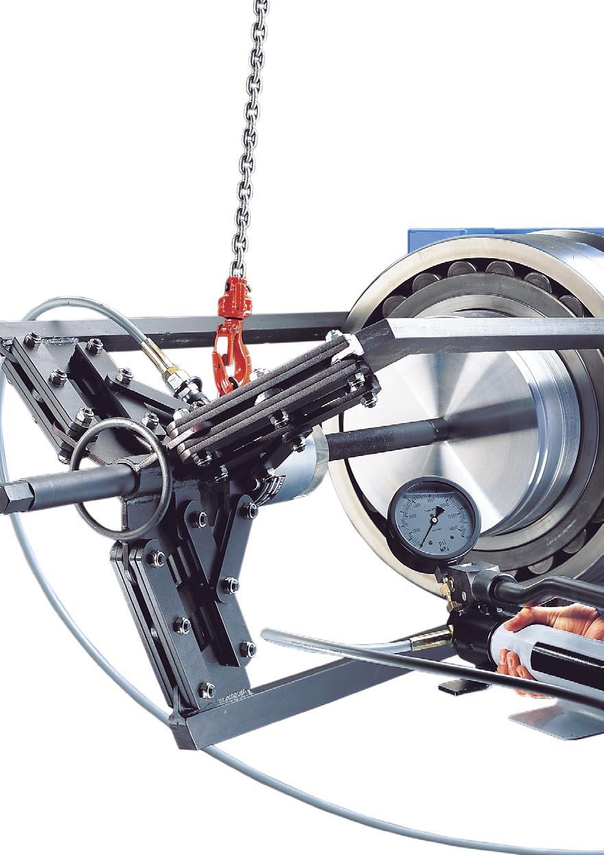
7 Dismounting Dismounting using the oil injection method The oil injection method can be used to dismount bearings with a cylindrical bore. This method injects oil under high pressure, with a viscosity of about 900 mm²/s at 20 C (70 F), between the shaft seat and the inner ring bore, until an oil film completely separates the contact surfaces ( fig. 7). If the bearing is removed promptly and without interruption, a relatively small force is required for dismounting. Fig. 7 Dismounting with a press A very convenient way to remove a bearing from its shaft seat is with a press placed against the shaft end. In this case, the bearing inner ring has to be supported ( fig. 8). Dismounting with heat Dismounting with heat is a suitable method when removing inner rings of needle roller bearings or NU, NJ and NUP design cylindrical roller bearings. Two different tools for this purpose are common: heating rings and induction heaters. Heating rings are typically used to mount and dismount the inner ring of small to medium-size bearings that are all the same size. Heating rings are made of a light alloy, radially slotted and equipped with insulated handles ( fig. 9). The dismounting procedure is simple. Coat the inner ring raceway of the bearing with an oxidation-resistant oil. Place the heating ring on a hot plate and heat it to approximately 280 C (540 F). Place the heated ring around the inner ring and press the handles together. The heat will transfer rapidly to the inner ring. As soon as the inner ring comes loose, withdraw both the tool and the inner ring. Then, remove the inner ring from the tool. Fig. 8 Fig
8 Dismounting rolling bearings If inner rings with different diameters are dismounted frequently, SKF recommends using an SKF Adjustable induction heater. These electrical induction heaters ( fig. 10) heat the inner ring rapidly without heating the shaft to any degree. If the inner ring is to be reused, it should be demagnetized after dismounting. For frequent dismounting of inner rings of medium-size and large cylindrical roller bearings, such as roll neck bearings in rolling mills, SKF recommends using an SKF Fixed induction heater. Heating rings and induction heaters are available from SKF. For additional information, visit Fig. 10 Dismounting a bearing fitted on a tapered shaft seat To avoid damaging the shaft or bearing during this dismounting process, properly support the shaft. To do this, use a suitable bench vice, two V-blocks ( fig. 11) or lifting tackle. Warning To avoid the risk of serious injury, attach a provision such as a lock nut to the shaft end to limit the bearing travel when it suddenly comes loose. Fig
9 Dismounting Manual dismounting Small bearings can be dismounted using a mechanical puller that engages the inner ring. Self-centring pullers equipped with springoperated arms should be used to simplify the procedure and avoid damage to the bearing seat. If it is not possible to apply the claws of the puller to the inner ring, withdraw the bearing via the outer ring or use a puller in combination with a pulling plate ( fig. 12). Dismounting with a hydraulically-assisted puller Larger bearings generally require considerable force and should be removed from their tapered seat with the aid of hydraulically-assisted pullers ( fig. 6, page 256). These are normally available for bearings with an outside diameter up to 500 mm. Dismounting using the oil injection method Dismounting medium-size and large bearings from tapered shafts is easier and much safer when the oil injection method is used. With this method, oil with a viscosity of about 900 mm²/s at 20 C (70 F) is injected under high pressure between the two tapered mating surfaces, via a supply duct and a distribution groove. This significantly reduces the friction between the two surfaces and produces an axial force that sep arates the bearing from its seat ( fig. 13). Warning To avoid the risk of serious injury, attach a provision such as a lock nut to the shaft end to limit the bearing travel when it suddenly comes loose. Dismounting a bearing fitted on an adapter sleeve The method used to dismount a bearing fitted on an adapter sleeve depends on the following: bearing size type of arrangement: plain or stepped shaft ( fig. 14) adapter sleeve design: with or without oil supply ducts and distribution grooves for oil injection ( fig. 15) In all cases, dismounting starts with the following ( fig. 16): Remove excess lubricant and wipe down the arrangement. Fig. 12 Fig
10 Dismounting rolling bearings Fig. 14 Fig. 15 Depending on the locking device: Disengage the bent tab of the lock washer from the lock nut (a). Loosen the locking screw in the lock nut ( b). Remove the locking clip attached to the lock nut (c). Loosen the lock nut a few turns ( d). Fig a b c d 261
11 Dismounting Manual dismounting: plain shafts Small bearings fitted on an adapter sleeve and a plain shaft can be dismounted by tapping a small steel block with an appropriate hammer, evenly around the bearing inner ring side face ( fig. 17). Before doing so, the sleeve lock nut has to be loosened a few turns. Also, to facilitate reassembly, mark the position of the sleeve on the shaft. After the bearing comes free, completely remove the lock nut, lock washer, bearing and sleeve from the shaft. To facilitate removal, expand the sleeve slightly by inserting a small plastic wedge or screwdriver in the slot of the sleeve. NOTE: The steel block shown in fig. 18 is a segment of a turned ring and can be made easily using the dimensions listed in the product tables of the SKF Interactive Engineering Catalogue, available online at will push the adapter sleeve underneath the abutment ring until the bearing comes free. To empty the hydraulic nut, open the oil release valve of the hydraulic pump, and push the piston back to its original position by screwing the nut down the threaded portion of the sleeve. Then, disconnect the hydraulic pump and remove the stop. Finally, unscrew the nut from the sleeve and remove both the bearing and sleeve from the shaft. NOTE: Detailed information about SKF hydraulic nuts is provided in the section Hydraulic tools, starting on page 73. Useful instructions for use can be found in the section The oil injection method, starting on page 62. Manual dismounting: stepped shafts Small bearings fitted on an adapter sleeve and a stepped shaft can be dismounted by a couple of sharp hammer blows applied to a mounting dolly abutting the lock nut of the adapter sleeve ( fig. 19). After the bearing comes free, completely remove the lock nut, lock washer as well as the bearing and withdraw the sleeve and the abutment ring from the shaft. To facilitate removal, expand the sleeve slightly by inserting a small plastic wedge or a screwdriver in the slot of the sleeve. NOTE: Use the SKF Bearing fitting tool kit for shaft diameters 55 mm ( page 72). Dismounting with a hydraulic nut Using a hydraulic nut for dismounting bearings fitted on an adapter sleeve on a stepped shaft makes bearing removal easy. To use this method however, it must be possible to mount a suitable stop for the piston of the hydraulic nut to work against ( fig. 20). The stop can be a washer or a plate bolted to the shaft end or can take the form of a two-piece ring fitted into a groove in the shaft and held in place by a one-piece ring. Place the hydraulic nut on the adapter sleeve with the piston facing outward. Be sure to leave a gap between the bearing and nut that is greater than the initial axial drive-up distance. Connect the hydraulic pump to the hydraulic nut. When pressurizing the hydraulic nut, the piston Fig
12 Dismounting rolling bearings Fig. 18 d 1 d d b +B a d 1 B a d a d b 60 Fig. 19 Fig
13 Dismounting Dismounting using the oil injection method Adapter sleeves equipped with an oil supply duct and an oil distribution groove facilitate dismounting because the oil injection method can be used ( fig. 21). This feature is standard for all SKF adapter sleeves with a bore diameter 200 mm, but can be supplied for sleeves with a bore diameter 140 mm. First, disengage the locking mechanism, and loosen the locking screw a few turns. Then, clean the threaded connection hole in the side face of the sleeve. Connect the hydraulic pump via an appropriate extension pipe to the adapter sleeve. Inject oil with a viscosity of about 900 mm²/s at 20 C (70 F) under high pressure between the two tapered mating surfaces via the supply duct and distribution groove in the sleeve. The bearing will dismount suddenly from its seat. After the hydraulic pump and extension pipe have been disconnected, remove the lock nut, lock washer, bearing and adapter sleeve from the shaft. Warning To avoid the risk of serious injury, attach a provision such as a lock nut to the shaft end to limit the bearing travel when it suddenly comes loose. NOTE: Detailed information about the oil injection method and useful instructions for use can be found in the section The oil injection method, starting on page 62. Dismounting a bearing fitted on a withdrawal sleeve The method used to dismount a bearing fitted on a withdrawal sleeve depends on the following: bearing size withdrawal sleeve design: with or without oil supply ducts and distribution grooves for oil injection ( fig. 22) In either case, dismounting starts with the following ( fig. 23): Remove excess lubricant and wipe down the arrangement. Remove the locking device, e.g. a lock nut and lock washer (a) or an end plate (b). Support the bearing, for example with lifting tackle (c). Manual dismounting Small and medium-size bearings fitted on a withdrawal sleeve can be dismounted with a lock nut and a hook or impact spanner ( fig. 24). Before screwing the lock nut onto the sleeve thread, lubricate the thread and that part of the lock nut facing the bearing inner ring with a molybdenum disulphide paste or a similar fric- Fig
14 Dismounting rolling bearings tion reducing substance. Tighten the lock nut until the withdrawal sleeve comes free. Finally, with the shaft properly supported, remove the sleeve and bearing from the shaft. Fig. 23 NOTE: If the threaded section of the sleeve protrudes beyond the shaft end or shaft shoulder, a support ring with the greatest possible wall thickness should be inserted in the sleeve bore to prevent distortion and damage to the thread when the nut is tightened ( fig. 24). Fig. 22 a b Fig c 265
15 Dismounting Dismounting with a hydraulic nut Medium-size and large bearings fitted on a withdrawal sleeve can be easily dismounted with a hydraulic nut. Fig. 25 Warning To avoid the risk of serious injury, attach a provision such as a lock nut for end plate to the shaft end ( fig. 25) to limit the withdrawal sleeve travel when it suddenly comes loose. Screw the hydraulic nut onto the thread of the withdrawal sleeve with the piston facing the bearing until the piston abuts the inner ring. Connect the hydraulic pump to the hydraulic nut and supply oil until the sleeve comes free. Once the sleeve is free, open the oil release valve of the hydraulic pump, so that the pressurized oil can leave the nut. Disconnect the hydraulic pump and remove the stop. Completely withdraw the sleeve from the shaft and remove the bearing. Fig. 26 NOTE: Detailed information about SKF hydraulic nuts is provided in the section Hydraulic tools, on page 73. Useful instructions for use can be found in the section The oil injection method, starting on page 62. Dismounting using the oil injection method Withdrawal sleeves with a bore diameter 200 mm are provided as standard with two oil supply ducts and an oil distribution groove in both the bore and outside surface. When using the oil injection method, two hydraulic pumps and appropriate extension pipes are needed ( fig. 26). First, clean the external thread as well as the threaded connection holes in the side face of the withdrawal sleeve. Screw the lock nut into position and tighten it. Connect both hydraulic pumps via the appropriate extension pipes to the sleeve. Inject oil with a viscosity of about 900 mm²/s at 20 C (70 F) under high pressure between the sleeve and the shaft through one duct and between the sleeve and bearing bore through the other one. The oil pressure between 266
16 Dismounting rolling bearings the mating surfaces will increase until it drops suddenly, which indicates that the mating surfaces have separated. While tightening the lock nut, using an impact spanner for example, the sleeve will come free. Disconnect the hydraulic pumps and completely withdraw the sleeve from the shaft by means of the lock nut. Finally, remove the bearing. Fig. 27 NOTE: Detailed information about the oil injection method and appropriate equipment is provided in the section The oil injection method, starting on page 62. Dismounting a bearing from a solid housing Most bearings have a loose fit in the housing and should be easy to remove. However, if the application requires a tight housing fit or if bearing damage such as fretting corrosion has occurred, the bearing may need to be removed by force. Manual dismounting Bearings with an outside diameter up to 120 mm that are mounted in a housing bore without shoulders can be removed with a mounting dolly placed against the outer ring of the bearing, and a hammer. To do this, use the SKF Bearing fitting tool kit ( page 72). Larger bearings require greater force to dismount and should be removed with a press. If an integral shoulder behind the bearing in the housing bore does not allow the use of a mounting dolly or press, use a hammer and a soft metal drift punch to drive the bearing out of the housing. Light hammer taps should be applied evenly around the whole side face of the outer ring ( fig. 27). Be careful when applying this method because it is very easy to damage the bearing and the housing bore. Housing shoulders that have threaded holes ( fig. 28) or slots ( fig. 29) enable the use of screws, a bearing puller or a hammer and a drift punch to drive the bearing from the housing. Fig. 28 Fig
17 Dismounting Small bearings with a bore diameter ranging from 7 to 60 mm that are mounted in a housing can be removed from a housing bore using an internal puller with a slide hammer, such as the SKF Internal bearing puller kit ( fig. 30). To do this, place the jaws of the appropriate extractor through the bearing bore by squeezing the spring mechanism to close the puller arms (a). By releasing the spring mechanism, the extractor firmly grips the inner ring shoulder (b). The bearing can be extracted from the housing bore by repeatedly striking the stop ring with the slide hammer (c). Fig. 31 Dismounting using the oil injection method If the necessary oil duct and distribution groove is designed into the housing and the bearing does not have a relubrication feature in the outer ring, the oil injection method can still be used. This method substantially reduces the amount of force required to remove larger bearings ( fig. 31). NOTE: Detailed information about the oil injection method can be found in the section The oil injection method, starting on page 62. Fig. 30 a b c 268
18 Dismounting rolling bearings Dismounting with heat Heating a housing to remove the bearing using, for example, a heater mat ( fig. 32), is not very common and should only be done as a last resort. Fig. 32 CAUTION: Never use a torch or other flame to heat the housing. Dismounting a bearing from a shaft and a solid housing simultaneously To dismount small deep groove ball bearings from a shaft and a solid housing simultaneously, special pullers (extractors) have been designed. Fig. 33 shows a puller designed for bearings with a bore diameter ranging from 10 to 100 mm. The puller arms are placed between the balls and grip the inner ring raceway, while being supported by the outer ring. Fig. 34 shows a puller designed for bearings with a bore diameter ranging from 30 to 160 mm. To apply the puller, the bearing cage needs to be removed first. The puller arms at the end are ball shaped with two flats. They are placed between the balls and grip both the inner and outer ring raceways. For additional information about internal bearing puller kits, visit Fig. 33 Fig
: Fig.")
19 Dismounting Dismounting bearing units What to remember SKF bearing units ( fig. 35) are available as plummer (pillow) block units, flanged units and take-up units. Depending on the size and type of bearing, they can be located on the shaft using any one of the following methods ( fig. 36): Fig. 35 grub (set) screw locking ( a) single grub (set) screw eccentric locking collar (b) adapter sleeve locking ( c) SKF ConCentra locking mechanism ( d, e) double grub (set) screw cylindrical collar locking (f) Therefore, the dismounting procedure and the tools appropriate for the job may differ. Appropriate tools include: a wrench or hexagonal key to loosen the attachment screws, bolts or nuts a hexagonal key to loosen the grub (set) screws in the inner ring or in the locking collar as specified in table 3, page 102 in the chapter Mounting bearing units a hook spanner to loosen the adapter sleeve lock nut as specified in table 4, page 103 in the chapter Mounting bearing units In some cases, a dead-blow hammer may be necessary. Hook spanners as well as dead blow hammers are part of the comprehensive range of SKF maintenance products. Detailed information can be found online at Once the bearing unit has been dismounted, check whether it can be reused. To do this, clean the outside surface of the unit, being careful not to damage the seals or get cleaning solvent into the bearing cavity. Turn the bearing slowly to feel for any damage. If applicable, relubricate the unit slowly via the grease fitting while rotating the inner ring. If it is determined that the unit is reusable, coat any untreated surfaces with grease, oil or anti-corrosive fluid to prevent corrosion. NOTE: Small bearing units, which are very dirty, are generally not worth cleaning. Normally it is more economical to scrap the bearing and replace it with a new one. 270
20 Dismounting bearing units Fig. 36 Warning To minimize the chance of serious injuries, prior to starting any work, perform required lockout/tagout procedures. a b c Preparations prior to dismounting Taking the time to prepare can make dismounting easier. If available, review the assembly drawing(s) and study the bearing unit arrangement. Then, before starting any work, do the following: Disconnect the power supply to the application. Clean the bearing unit and surrounding area thoroughly. Wipe the shaft clean. Check the locking method and choose appropriate tools for dismounting the bearing units. Check for and repair any damage that may prevent the unit from sliding off the shaft. Support the shaft to relieve any load on the bearing. d 10 e f 271
, carefully read the guidelines provided under What to remember, starting on page 270, and do the following: 1 Loosen the grub (set) screws in the inner ring of both units, at least a full turn (")
21 Dismounting Dismounting ball bearing units with grub (set) screw locking When dismounting ball bearing units with grub (set) screw locking ( fig. 37), carefully read the guidelines provided under What to remember, starting on page 270, and do the following: 1 Loosen the grub (set) screws in the inner ring of both units, at least a full turn ( fig. 38) 2 Unscrew and remove the attachment bolts. For take-up units, disconnect the adjustment screw in the cast hole of both units. 3 Remove the units from the shaft. For take-up units, pull the complete shaft/ units assembly out of the take-up frames and remove the units from the shaft. For pressed steel plummer (pillow) block units, remove the housing caps, lift out the shaft and remove the bearings from the shaft. For pressed steel flanged units, remove the first housing cap and slide the bearing off the shaft. Then repeat on the other side. Fig. 37 Fig
, carefully read the guidelines provided under What to remember, starting on page 270, and do the following ( fig. 40): Fig.")
22 Dismounting bearing units Dismounting ball bearing units with an eccentric locking collar When dismounting ball bearing units with an eccentric locking collar ( fig. 39), carefully read the guidelines provided under What to remember, starting on page 270, and do the following ( fig. 40): Fig Loosen the grub (set) screw in the eccentric locking collar of both units, at least a full turn (a). 2 Loosen the locking collar in the opposite direc tion of rotation. To do this: Place a drift punch in the blind hole in the circumference of the collar and hit it with a hammer. Or use a hook spanner with a stud en gaging the blind hole in the circumference of the collar (b). 3 Remove the eccentric locking collar of both units from the shaft. 4 Unscrew and remove the attachment bolts. For take-up units, disconnect the adjustment screw in the cast hole of both units. 5 Remove the units from the shaft. For take-up units, pull the complete shaft/ units assembly out of the take-up frames and remove the units from the shaft. For pressed steel plummer (pillow) block units, remove the housing caps, lift out the shaft and remove the bearings from the shaft. For pressed steel flanged units, remove the first housing cap and slide the bearing off the shaft. Then repeat on the other side. a Fig b 273
23 Dismounting Dismounting ball bearing units fitted on an adapter sleeve When dismounting a ball bearing unit with an adapter sleeve ( fig. 41), carefully read the guidelines provided under What to remember, starting on page 270, and do the following ( fig. 42): 1 Disengage the bent tab of the lock washer from the lock nut slot (a) and unscrew the lock nut a few turns. 2 Loosen the attachment bolts or nuts a few turns. 3 Units with access to the opposite side of the locking device can be separated from the adapter sleeve with a steel block or drift punch and a hammer (b). Units without access to the opposite side of the locking device can be separated from the adapter sleeve by a couple of sharp hammer blows applied to a mounting dolly abutting the lock nut of the adapter sleeve (c). Fig. 41 Fig. 42 NOTE: Use the SKF Bearing fitting tool kit for shaft diameters 55 mm ( page 72). 4 Unscrew the lock nut and remove the lock washer on both units. 5 Remove the attachment bolts or nuts and slide the units off the sleeve along the shaft. 6 Remove the adapter sleeve from the shaft. To facilitate removal, expand the sleeve slightly by inserting a plastic wedge or a screwdriver in the slot of the sleeve. a b c 274
, carefully read the guidelines provided under What to remember, starting on page 270, and do the following ( fig.")
24 Dismounting bearing units Dismounting SKF ConCentra ball bearing units Prior to dismounting an SKF ConCentra ball bearing unit ( fig. 43), carefully read the guidelines provided under What to remember, starting on page 270, and do the following ( fig. 44): 1 Loosen the grub (set) screws in the mounting ring of both units a few turns (a). 2 Loosen the attachment bolts or nuts of both units, but do not remove them. 3 Displace the mounting side ring until the SKF ConCentra stepped sleeve comes free: by tapping the end of the shaft with a hammer (b) by tapping a mounting dolly placed against the mounting ring (c) NOTE: Use the SKF Bearing fitting tool kit for shaft diameters 55 mm ( page 72). Fig. 43 Fig Remove the attachment bolts and remove the units from the shaft. a 10 b c 275
, carefully read the guidelines provided under What to remember, starting on page 270, and do the following ( fig. 46): 1 Loosen the attachment bolts and remove them.")
 screws in the mounting collar by a few turns (b).")
25 Dismounting Dismounting SKF ConCentra roller bearing units When dismounting roller bearing units with a plummer (pillow) block housing with SKF Con- Centra locking ( fig. 45), carefully read the guidelines provided under What to remember, starting on page 270, and do the following ( fig. 46): 1 Loosen the attachment bolts and remove them. If possible, lift the complete bearing arrangement, i.e. shaft, both bearing units and associated components, out first, before dismounting the bearing units (a). 2 Place a support under the shaft. 3 Start with the locating bearing unit. 4 Loosen the grub (set) screws in the mounting collar by a few turns (b). 5 Face the mounting collar and while holding the base, pull the bearing unit until it releases from the shaft (c). The energy from the preloaded wave spring facilitates the release from the shaft. But, if necessary, use a rubber hammer to tap the collar on the opposite side of the unit (d). 6 Withdraw the bearing unit from the shaft. 7 To dismount the non-locating bearing unit, repeat steps 4 to 6. Fig. 45 Fig. 47 Dismounting roller bearing units with a cylindrical locking collar When dismounting a roller bearing unit with a cylindrical locking collar ( fig. 47), carefully read the guidelines provided under What to remember, starting on page 270, and do the following: 1 Loosen the two grub (set) screws in the cylindrical locking collar of both units a few turns. 2 Unscrew and remove the attachment bolts. For take-up units, disconnect the adjustment screw in the cast hole of both units. 3 Remove the units from the shaft. If needed, use a rubber hammer and lightly tap the unit until it releases from the shaft. For take-up units, pull the complete shaft/ unit assembly out of the take-up frame and remove the unit from the shaft. 276
26 Dismounting bearing units Fig. 46 a b c 10 c d 277
27 Dismounting Dismounting bearing housings Bearing housings, which are used in a variety of industrial applications, are available in a wide range of designs and sizes. Information about how to dismount and disassemble the most popular plummer (pillow) block housings and flanged housings ( fig. 48) can be found in this section. To obtain dismounting instructions for housings not included here, contact the SKF application engineering service. What to remember If a housing is to be used again, always dismount it carefully, taking the following into consideration: Keep the components of each housing together. The base and cap of individual housings are not interchangeable. The base and cap of SKF SNL, SONL and SAF housings are marked with a serial number. Handle all metal parts of solid seals carefully. Do not hit the housing directly with a hammer. Warning To minimize the chance of serious injuries, prior to starting any work, perform required lockout/tagout procedures. Preparations prior to dismounting Taking the time to prepare can make dismounting easier. If available, review the assembly drawing(s) and study the bearing arrangement. Then, before starting any work, do the following: Disconnect the power supply to the application. Clean the housings and surrounding area thoroughly. Support the shaft with something such as lifting tackle. For split plummer (pillow) block housings, be sure that the proper tools are available to lift the shaft out of the housing base(s) ( fig. 49). Have suitable containers on hand to retrieve lubricant samples and collect the used lubricant. Check the housings for cracks prior to reuse. If a housing is deemed reusable, apply a coating of grease or oil to any unpainted surfaces to protect against corrosion. 278

28 Dismounting bearing housings Fig. 48 Fig
, carefully read the guidelines provided under What to remember on page 278, and do the following ( fig. 51): Fig.")

. NOTE: All current SKF housings are provided with notches in the base and cap to accommodate a screwdriver or a pry bar.")
 rings, if applicable (d). CAUTION: Do not reuse any contact seals.")
29 Dismounting Dismounting split plummer (pillow) block housings When dismounting a standard plummer (pillow) block housing ( fig. 50), carefully read the guidelines provided under What to remember on page 278, and do the following ( fig. 51): Fig Remove any auxiliary connections to the housing, e.g. lubricant feed lines or other devices. Loosen and remove the attachment bolts or nuts on both housings. NOTE: If possible, lift the complete assembly (shaft, housings and other components) to a clean, open area. 3 Loosen and remove the cap bolts on both housings. 4 Remove the housing caps ( a). NOTE: All current SKF housings are provided with notches in the base and cap to accommodate a screwdriver or a pry bar. 5 If applicable, remove any excess grease and split seals from the housing caps (b). 6 Lift the shaft assembly from the housing bases (c). 7 Remove the other seal halves or the end cover, and the locating (stabilizing) rings, if applicable (d). CAUTION: Do not reuse any contact seals. 8 Remove any excess grease from the housing base. 9 Remove any solid seals from the shaft (e). V-rings can be cut. 10 Dismount the bearings from the shaft. 11 Remove the second sealing washer or ring from the shaft. note: Make sure all components for each housing are kept together. 280
30 Dismounting bearing housings Fig. 51 b a c 10 d e 281
: Fig. 52 1 Loosen and remove the cover bolts on both housings. 2 Remove the cover and the locating ( stabilizing) rings, if fitted.")
31 Dismounting Dismounting flanged housings When dismounting a standard flanged housing ( fig. 52), carefully read the guidelines provided under What to remember on page 278 and do the following ( fig. 53): Fig Loosen and remove the cover bolts on both housings. 2 Remove the cover and the locating ( stabilizing) rings, if fitted. 3 Remove any excess grease from the cover and housing to expose the locking device on the adapter sleeve. 4 Disengage the bent tab of the lock washer from the lock nut slot and unscrew the lock nut a few turns (a). 5 Loosen the attachment bolts or nuts, but do not remove them. 6 Separate the bearing from the adapter sleeve by hitting the shaft ends with a hammer (b) by hitting a mounting dolly abutting the lock nut (c) NOTE: Use the SKF Bearing fitting tool kit for shaft diameters 55 mm ( page 72). 7 Unscrew the lock nut and remove the lock washer on both sides. 8 Remove the attachment bolts or nuts. 9 Separate the housing from its support surface and slide the housing, bearing and adapter sleeve off the shaft. 10 Use a puller if additional force is needed to free the bearing from the shaft (d). 11 Cut the seal from the seal groove ( e). 12 Remove excess grease from the housing behind the bearing. 13 Dismount the bearing following the instructions listed under Dismounting a bearing from a solid housing, starting on page 267. NOTE: Make sure all components for each housing are kept together. 282
32 Dismounting bearing housings Fig. 53 a b c 10 d e 283
33 Dismounting Removing seals Fig. 54 Generally, there are two different types of seals protecting rolling bearing arrangements: noncontact seals and contact seals. Removing non-contact seals Non-contact seals ( fig. 54) generate almost no friction, enabling them to last a very long time. In most cases, these seals are reusable. Therefore, they should be removed very carefully, with the correct tools. Never hit a noncontact seal with a hammer or use a screwdriver or sharp drift punch during the removal process. Prior to removing these seals, check for and repair any shaft damage that otherwise may damage the seal when sliding it off the shaft. Removing contact seals Contact seals ( fig. 55), which are typically fixed in a housing and slide on a counterface, such as a shaft or distance ring, with a defined radial force, will wear over the time. Therefore, they should never be reused. However if the cause of a seal failure is to be analyzed, they should be treated carefully during removal. Fig
34 Removing seals Radial shaft seals can be removed by: Fig. 58 a hammer and a drift punch, if the housing shoulder has vent holes ( fig. 56) a screwdriver, if the front or back face of the seal is accessible ( fig. 57) tongs to grip the hinge or the shell of the seal ( fig. 58) a mounting dolly, e.g. the SKF Bearing fitting tool kit ( fig. 59) a hook to grip the shell from behind ( fig. 60) Fig. 56 Fig. 59 Fig. 57 Fig
35 Dismounting V-ring seals can be removed by: Fig. 62 stretching them over other components ( fig. 61) cutting them with scissors ( fig. 62) Large all-elastomer radial shaft seals can be removed by: stretching or cutting them with scissors ( fig. 63) disconnecting the spring connector on split seals ( fig. 64) Fig. 63 Fig. 61 Fig
36 Removing seals
15. Bearing Handling Storage Fitting A-97
 15. Bearing Handling Bearings are precision parts, and in order to preserve their accuracy and reliability, care must be exercised in their handling. In particular, bearing cleanliness must be maintained,
Bearing Handling. 15. Bearing Handling Bearing storage Installation
 15. Bearing Handling Bearings are precision parts and, in order to preserve their accuracy and reliability, care must be exercised in their handling. In particular, bearing cleanliness must be maintained,
Mounting and dismounting
 Mounting and dismounting General information... 258 Where to mount... 258 Preparations for mounting and dismounting... 258 Bearing handling... 260 Mounting... 261 Mounting bearings with a cylindrical bore...
Mounting rolling bearings
 Mounting rolling bearings Preparations prior to mounting... 46 Planning... 46 Cleanliness... 46 Removing the preservative from new bearings..................... 47 Checking associated components..... 47
16 Bearing accessories
 Rolling bearings 16 Bearing accessories Adapter sleeves... 1270 Designs and variants... 1270 Basic design... 1270 Variants for oil injection... 1270 Variants for CARB toroidal roller bearings... 1273
Maintenance and lubrication products
 Maintenance and lubrication products Mechanical tools... 1070 Hook and impact spanners... 1070 Lock nut spanners and axial lock nut sockets... 1070 Bearing fitting tools... 1070 Jaw pullers... 1071 Strong
Installation Procedures
 For the precision ball and roller bearings supplied by MRC Bearings, skill and cleanliness while handling, mounting and dismounting are necessary to ensure satisfactory bearing performance. As precision
Instruction Manual for HSPA Take-Up Units
 Installation Instruction Manual for HSPA Take-Up Units Warning: To ensure the drive is not unexpectedly started, turn off and lockout the power source before proceeding. Failure to observe these precautions
3. BEARING ARRANGEMENT DESIGN
 3. BEARING ARRANGEMENT DESIGN 3.1 GENERAL PRINCIPLES OF ROLLING BEARING ARRANGEMENT DESIGN Rotating shaft or another component arranged in rolling bearings is guided by them in radial as well as in axial
1988 Chevrolet Pickup V SUSPENSION - FRONT (4WD)' 'Front Suspension - "V" Series 1988 SUSPENSION - FRONT (4WD) Front Suspension - "V" Series
' 'Front Suspension - V Series 1988 SUSPENSION - FRONT (4WD) Front Suspension - V Series") 1988 SUSPENSION - FRONT (4WD) Front Suspension - "V" Series DESCRIPTION NOTE: Vehicle serial numbers used in this article has been abbreviated for common reference to Chevrolet and GMC models. Chevrolet
1988 SUSPENSION - FRONT (4WD) Front Suspension - "V" Series DESCRIPTION NOTE: Vehicle serial numbers used in this article has been abbreviated for common reference to Chevrolet and GMC models. Chevrolet
4 Self aligning ball bearings
 Rolling bearings 4 Self aligning ball bearings Designs and variants... 538 Basic design bearings... 539 Bearings with an extended inner ring.. 540 Cages... 540 Sealing solutions... 540 Greases for sealed
Dismounting of rolling bearings Mechanical dismounting
 Mechanical dismounting Dismounting methods Mechanical dismounting In order to prevent damage during the dismounting of bearings, various dismounting methods are used depending on the bearing size and type
1989 Jeep Cherokee. STEERING COLUMN' '1989 STEERING Jeep Steering Columns STEERING COLUMN STEERING Jeep Steering Columns
 STEERING COLUMN 1989 STEERING Jeep Steering Columns DESCRIPTION All models use collapsible steering columns. All columns have integral ignition switch and locking device. Optional tilt wheel is available
Bearing Installation and Maintenance Guide
 Bearing Installation and Maintenance Guide Highlights of the new edition of the SKF Bearing Installation and Maintenance Guide. The mounting and dismounting section has been expanded to include: -- Individual
Maintenance Information
 16572679 Edition 2 May 2014 Air Drill QP Series Maintenance Information Save These Instructions Product Safety Information WARNING Failure to observe the following warnings, and to avoid these potentially
 AUTOGARD SERIES 820 TORQUE LIMITER Installation and Maintenance Manual DB0009 Issue 11 21 Feb 2017 British Autogard Ltd 2 Wilkinson Rd., Love Lane Industrial Estate, Cirencester, Glos., GL7 1YT UK Tel.
1984 Dodge W250 PICKUP
 1984 Dodge W250 PICKUP Submodel: Engine Type: V8 Liters: 5.2 Fuel Delivery: CARB Fuel: GAS Dana 44 MODELS THROUGH 1984 2. Raise and safely support the vehicle, then remove the wheel hub and bearings as
FUNCTION OF A BEARING
 Bearing FUNCTION OF A BEARING The main function of a rotating shaft is to transmit power from one end of the line to the other. It needs a good support to ensure stability and frictionless rotation. The
Instruction Manual for PTI Split Block Bearing Units For SAF, SDAF, SN, SNG, SNHF, S3000K & SD Series Housings
 Instruction Manual for PTI Split Block Bearing Units For SAF, SDAF, SN, SNG, SNHF, S3000K & SD Series Housings Installation SDAF SD & S3000 SAF Warning: To ensure that the drive is not unexpectedly started,
Maintenance Information
 45528270 Edition 1 June 2007 Barring Motor T480 Series Maintenance Information Save These Instructions WARNING Always wear eye protection when operating or performing maintenance on this Barring Motor.
Split plummer block housings SONL series
 Split plummer block housings SONL series Bearing types Self-aligning ball bearings Spherical roller bearings CARB toroidal roller bearings Bearing dimension series 22 Shaft diameter range 75 to 240 mm
 DRUM BRAKE RIMS Periodic inspection of drum brake rims is necessary to determine indications of uneven or excessive wear. In general, brake rim failures other that regular wear are caused by brake linings
Maintenance Information
 16573370 Edition 2 February 2014 Air Grinder 99V Series Maintenance Information Save These Instructions Product Safety Information WARNING Failure to observe the following warnings, and to avoid these
3M Overhaul Service Kit
 SERVICE INSTRUCTIONS FOR 3M 12,000 RPM 5 in. (127 mm) and 6 in. (150 mm) RANDOM ORBITAL SANDERS 3M Overhaul Service Kit The part number 20347, 3M Overhaul Service Kit, contains all the replacement parts
TECHNICAL INFORMATION
 Radial Roller Bearings Fitting and Mounting Fixed Bearings and Float Bearings Radial and axial loads in bearing units can be transmitted by fixed and floating bearings A fixed bearing is generally used
Maintenance Information
 Form 04584058 Edition 1 November 2004 Air Impactool 2141P and 2141PSP Maintenance Information Save These Instructions Disassembly General Instructions 1. Do not disassemble the tool any further than necessary
3M Overhaul Service Kit
 SERVICE INSTRUCTIONS FOR 3M 12,000 RPM 3 in. (77 mm) RANDOM ORBITAL SANDERS 3M Overhaul Service Kit The part number 20346, 3M Overhaul Service Kit, contains all the replacement parts that naturally wear
Fitting-removal and maintenance
 Fitting-removal and maintenance Fitting of bearings 136 General rules 136 Fitting principles 136 Hot fitting 137 Press fitting (or with anti-rebound hammer) 138 Adapter sleeves 139 Removal of bearings
Technical Information
 Technical Information TI No. WL 80-48 E April 1999 Rolling Bearings FAG Mechanical Extractors Small rolling bearings with bore diameters of up to about 100 mm which have an interference fit on the shaft
BEARING MAINTENANCE. Mounting. Lubrication. Dismounting
 BEARING MAINTENANCE Mounting. Lubrication. Dismounting 1 IMPORTANCE OF PROPER MOUNTING PROCEDURES Ensure safety Simplicity and speed the process Using full bearing capabilities Get the longest possible
MA-CFB_BEARING /2014 RZR VZR TZR RER
 Belt Driven Centrifugal Fans with deep groove ball bearing, self-aligning bearing or swivel-joint roller bearing (Translation of the Original) MA-CFB_BEARING 4.3 /204 RZR VZR TZR RER Deep groove ball bearing
Installation Instructions
 Preparing your vehicle to install your brake system upgrade 1. Rack the vehicle. 2. If you don t have a rack, then you must take extra safety precautions. 3. Choose a firmly packed and level ground to
PROPELLER SHAFT & DIFFERENTIAL CARRIER SECTIONPD CONTENTS
 PROPELLER SHAFT & DIFFERENTIAL CARRIER SECTIONPD CONTENTS PREPARATION...2 PROPELLER SHAFT...5 On-Vehicle Service...6 Removal and Installation...7 Inspection...7 Disassembly...7 Assembly...8 ON-VEHICLE
SKF Maintenance and Lubrication Products
 SKF Maintenance and Lubrication Products Dismounting Buy a bearing Basic condition monitoring Mounting Alignment Lubrication Extending the Bearing Life Cycle Mounting & dismounting Mechanical tools 10
MAINTENANCE ROAD 2013 WHEELS TECHNICAL MANUAL
 2013 WHEELS TECHNICAL MANUAL ROAD CYCLOCROSS PISTA GROUPSET TYPE OPERATION REVISION DESCRIPTION ROAD GROUPSETS CONE / CUP MOVEMENT 002 1/2011 SERVICING FRONT HUB ASSEMBLY PRODUCTS ON WHICH THE PROCEDURE
Axial-radial cylindrical roller bearings
 Axial-radial cylindrical roller bearings Designs and variants.............. 320 Bearing data..................... 321 (Boundary dimensions, tolerances) Product table 5.1 Axial-radial cylindrical roller
Fluid-O-Tech ROTOFLOW ROTARY VANE PUMP REBUILD MANUAL
 Fluid-O-Tech PUMP TECHNOLOGY AT ITS BEST WWW.FLUID-O-TECH.COM Office: 161 Atwater St., Plantsville, CT 06479 Phone: (860) 276-9270 Fax: (860) 620-0193 ROTOFLOW ROTARY VANE PUMP REBUILD MANUAL 08/09 Ed.,
A basic layout diagram of a papermaking machine is shown below :
 Introduction : A papermaking machine consists of the following sections : A wire and press section (the wet section) A drier section A calender & 4. A reeler A basic layout diagram of a papermaking machine
Split plummer block housings SE 2, 3, 5 and 6 series
 Split plummer block housings SE 2, 3, 5 and 6 series 3 Bearing types Self-aligning ball bearings Spherical roller bearings CARB toroidal roller bearings Bearing dimension series 02, 03, 22, 23, 32 Shaft
Hydraulic Motors. Radial Piston Motors with fixed displacement Series RM...X Vg = 250 cm³/u cm³/u. Repair manual. Doc.-No.
 Hydraulic Motors Radial Piston Motors with fixed displacement Series RM...X Vg = 250 cm³/u - 900 cm³/u Doc.-No. HM3-005 UK Seite 2 Table of contents 1. General... 3 2. Dismantling the distributor unit...
Maintenance Information
 16575243 Edition 2 October 2013 Air Screwdrivers 1R Series Maintenance Information Save These Instructions Product Safety Information WARNING Failure to observe the following warnings, and to avoid these
CLUTCH CONTENTS SERVICE DIAGNOSIS. (a) Worn or damaged disc assembly. (b) Grease or oil on disc facings. (c) Improperly adjusted cover assembly.
 Worn or damaged disc assembly. (b) Grease or oil on disc facings. (c) Improperly adjusted cover assembly.") CLUTCH CONTENTS -GROUP 6 Page CLUTCH HOUSING ALIGNMENT... 6 CLUTCH PEDAL FREE PLAY 1 CLUTCH RELEASE BEARING 5 CLUTCH RELEASE FORK... 5 CLUTCH SERVICING 2 PILOT BUSHING CRANKSHAFT TO TRANSMISSION DRIVE
CLUTCH CONTENTS -GROUP 6 Page CLUTCH HOUSING ALIGNMENT... 6 CLUTCH PEDAL FREE PLAY 1 CLUTCH RELEASE BEARING 5 CLUTCH RELEASE FORK... 5 CLUTCH SERVICING 2 PILOT BUSHING CRANKSHAFT TO TRANSMISSION DRIVE
TC20 Chain Driven Power Take-Off Overhaul Instructions
 TC20 Chain Driven Power Take-Off Overhaul Instructions Table of Contents Section Page Introduction 4 Ordering Repair Parts 4 General Information 5 Special Tools 6 Disassembly See Page 2 Reassembly See
Maintenance Information
 16573347 Edition 2 February 2014 Air Grinder Series 88H Maintenance Information Save These Instructions Product Safety Information WARNING Failure to observe the following warnings, and to avoid these
A/C COMPRESSOR SERVICING Article Text 1991 Saab 9000 For Copyright 1997 Mitchell International Friday, October 15, :22PM
 Article Text ARTICLE BEGINNING 1991 GENERAL SERVICING Compressor Service * PLEASE READ THIS FIRST * CAUTION: When discharging air conditioning system, use only approved refrigerant recovery/recycling equipment.
Amarillo PUMP DRIVES (250 HP THROUGH 350 HP) INSTRUCTIONS FOR REPAIRING MODELS 250, 300, and 350
 INSTRUCTIONS FOR REPAIRING MODELS 250, 300, and 350") Amarillo PUMP DRIVES (250 HP THROUGH 350 HP) INSTRUCTIONS FOR REPAIRING MODELS 250, 300, and 350 Amarillo Right Angle Pump Drives, if properly installed and maintained, should provide years of service
Amarillo PUMP DRIVES (250 HP THROUGH 350 HP) INSTRUCTIONS FOR REPAIRING MODELS 250, 300, and 350 Amarillo Right Angle Pump Drives, if properly installed and maintained, should provide years of service
Home at last. The new FNL fl anged bearing housing
 Home at last The new FNL fl anged bearing housing Approved by the family Previously it was blue-green. Yet was seen as the black sheep of the family. Now it s the other way around. FNL offers everything
INSTRUCTION MANUAL AND PARTS LIST FOR SERIES 8L-630J AND 630M WARNING
 INSTRUCTION MANUAL AND PARTS LIST FOR SERIES 8L-630J AND 630M WARNING READ CA-l AND TIDS INSTRUCTION MANUAL PRIOR TO INSTALLATION, OPERATION OR MAINTENANCE WARNING This Instruction Manual and General Instructions
2003 Dodge Pickup R DRIVE AXLES' 'Axle Shafts - Front - Ram Pickup WD DRIVE AXLES
 2002-04 DRIVE AXLES Axle Shafts - Front - Ram Pickup 1500 4WD DESCRIPTION Vehicles equipped with 4WD and C205F front axle assembly use equal length axle shaft system to deliver power from front differential
SCAMP AND UTILITY MODELS SELF-PROPELLED BELT DRIVE SERVICING 4502, 4503, 8602, 8603 WITH F SERIES ENGINES
 4502, 4503, 8602, 8603 WITH F SERIES ENGINES Adjustments and servicing of the Scamp and Utility self-propelled mowers are very different from all previous models of self-propelled mowers. BEFORE ANY ADJUSTMENTS
15E INSOCOAT bearings
 15E INSOCOAT bearings Designs and variants............... 1206 INSOCOAT bearings with a coated outer ring......................... 1207 INSOCOAT bearings with a coated inner ring.........................
DESCRIPTION Acura TSX SUSPENSION Front - TSX. NOTE: For system description and component location, see Fig. 1.
 2004 SUSPENSION Front - TSX DESCRIPTION NOTE: For system description and component location, see Fig. 1. Fig. 1: Identifying Front Suspension Components Wednesday, March 12, 2008 8:30:45 8:30:55 PM Page
Bearings for Fans. Bearing arrangements for fans
 1.1.1. Bearings for Fans Bearing arrangements for fans Summary The large variety of fans can be classified in different ways. Generally, there are two categories that are based on the fan s directions
Chapter 11 Rolling Contact Bearings
 Chapter 11 Rolling Contact Bearings 1 2 Chapter Outline Bearing Types Bearing Life Bearing Load Life at Rated Reliability Bearing Survival: Reliability versus Life Relating Load, Life, and Reliability
3.2 DRIVE TORQUE HUB. Roll, Leak and Brake Testing SECTION 3 - CHASSIS & TURNTABLE. 3-2 JLG Lift
 3.2 DRIVE TORQUE HUB Roll, Leak and Brake Testing 10 LUG PATTERN Torque-Hub units should always be roll and leak tested before disassembly and after assembly to make sure that the unit's gears, bearings
 Page 1 of 15 Transmission, Model S5-42 ZF Model S5-42 ZF Disassembly NOTE: For 4x4 and F-Super Duty vehicles, skip to Step 5. 1. Attach the transmission to the Bench Mounted Holding Fixture T57L-500-B
354 CHAPTER EIGHT WATER PUMP
 354 CHAPTER EIGHT 33 Shift handle F : Forward N : Neutral R : Reverse proper alignment of the water tube to the water pump opening during each installation attempt. Make sure the locating pins enter the
DODGE USN 500 and 600 Series Adapter Mount & 200 and 300 Series Direct Mount Plummer Blocks
 DODGE USN 500 and 600 Series Adapter Mount & 200 and 300 Series Direct Mount Plummer Blocks These instructions should be read thoroughly before installation or operation. GENERAL INFORMATION WARNING: To
Sachs shock manual. ( ) 2 & 4 Stroke RR Enduro. ( ) RS Dual Sport
 2 & 4 Stroke RR Enduro. ( ) RS Dual Sport") Sachs shock manual (2013 2015) 2 & 4 Stroke RR Enduro (2014-2015) RS Dual Sport 1 Introduction The procedures in this manual must take place in a clean environment using professional tools and some specific,
Sachs shock manual (2013 2015) 2 & 4 Stroke RR Enduro (2014-2015) RS Dual Sport 1 Introduction The procedures in this manual must take place in a clean environment using professional tools and some specific,
Link-Belt Mounted& Unmounted Ball Bearings
 Link-Belt ed& Unmounted Ball Bearings WARNING: These instructions should be read entirely and followed carefully before attempting to install or remove Link-Belt Ball bearings. Failure to do so can result
Overhaul Special Tools Required
 1 of 31 Overhaul - Special Tools Required - Cylinder end seal remover attachment, 07NAD-SR3020A - Pilot collar, 07GAF-PH70100 - Valve seal ring sizing tool, 07NAG-SR3090A - Ball joint boot clip guide,
SKF Heavy Duty Jaw Pullers TMMP * 4.7* TMMP * 8.2* TMMP * 13.4*
 Dismounting Selection chart SKF external pullers 22 25 22 Designation Width of grip Effective arm length mm in. mm in. SKF Standard Jaw Pullers TMMP 2x65 1565 0.62.6 60 2.4 TMMP 2x170 25170 1.06.7 135
TROUBLESHOOTING SPECIAL TOOL ASSEMBLY AND ADJUSTMENT
 1 INDEX Models FD, FE, FF and SG REAR AXLE 10-1 10-108E-07 CHAPTER 10 REAR AXLE Models FD, FE, FF and SG TROUBLESHOOTING...10-2 10 SPECIAL TOOL...10-3 WHEEL HUB AND RELATED PARTS DISASSEMBLY...10-7 INSPECTION...10-9
Service Tools. Service and Repair Manual Model 900/950/990 ITEM PART NO. DESCRIPTION ITEM PART NO. DESCRIPTION ITEM PART NO.
 12 1 3 2 4 5 8 10 6 7 9 11 14 24 12 13 17 22 29 18 23 25 19 26 15 20 27 21 16 22 33 37 38 32 31 36 30 34 35 40 41 42 43 ITEM PART NO. DESCRIPTION 1 9170 0231 30 LONG ALLEN KEY 2 9170 0737 20 3/32 PIN PUNCH
Maintenance Information
 16573321 Edition 3 February 2014 Air Grinder Series 61H Maintenance Information Save These Instructions Product Safety Information WARNING Failure to observe the following warnings, and to avoid these
SERVICE MANUAL L130B / L4130 Series Logstacker Drive Axle With Bolt-On Stub End Retainer
 SERVICE MANUAL L130B / L4130 Series Logstacker Drive Axle With Bolt-On Stub End Retainer Page 1 Allied Form #80-930 Rev 07/2009 SERVICE MANUAL LOG STACKER DA202 DRIVE AXLE TABLE OF CONTENTS PROCEDURE FOR
This file is available for free download at
 This file is available for free download at http://www.iluvmyrx7.com This file is fully text-searchable select Edit and Find and type in what you re looking for. This file is intended more for online viewing
DODGE USAF 500 SERIES Pillow Blocks
 INSTRUCTION MANUAL for ADAPTER MOUNTED DODGE USAF 500 SERIES Pillow Blocks WARNING: Because of the possible danger to person(s) or property from accidents which may result from the improper use of products,
Split plummer block housings SED 30, 31, 32 and 39 series
 Split plummer block housings SED 30, 31, 32 and 39 series Bearing types Spherical roller bearings Bearing dimension series 30, 31, 32 and 39 Shaft diameter range 430 to 900 mm Typical shaft-bearing combinations
GatesFacts Technical Information Library Gates Compass Power Transmission CD-ROM version 1.2 The Gates Rubber Company Denver, Colorado USA
 MAKING THE RIGHT SHAFT CONNECTIONS Daniel Schwartz & Gary Porter Power Transmission Design August, 1996 Securing a belt pulley to a drive shaft often seems like such a routine task, that engineers and
1 Mounting V-belt drive (motor pulley, fly wheel, V-belts and guard)
") Mounting V-belt drive (motor pulley, fly wheel, V-belts and guard) General safety instructions, requirements and procedures 1 Mounting V-belt drive (motor pulley, fly wheel, V-belts and guard) 1.1 General
Mounting V-belt drive (motor pulley, fly wheel, V-belts and guard) General safety instructions, requirements and procedures 1 Mounting V-belt drive (motor pulley, fly wheel, V-belts and guard) 1.1 General
UNIVERSAL JOINTS AND PROPELLER SHAFT
 Section XII UNIVERSAL JOINTS AND SERVICE BULLETIN REFERENCE NUMBER DATE SUBJECT CHANGES UNIV JOINTS AND 537 UNIVERSAL JOINTS AND DATA AND SPECIFICATIONS Propeller Shaft Number used C-67 C-68 C-69 C-70
Char-Lynn Hydraulic Motor. Repair Information Series. April, 1997
 Char-Lynn Hydraulic Motor April, 1997 Repair Information Geroler Motors 002 00 004 Parts Drawing 1 See Note 2 Page 1 22 1 9 1-1/4 Split Flange Ports 8 7 6 5 B 1 See Note 2 Page 2 24 4 14 19 20 15 1 18
DRIVE AXLE Nissan 240SX DESCRIPTION & OPERATION AXLE RATIO & IDENTIFICATION AXLE SHAFT & BEARING R & I DRIVE SHAFT R & I
 DRIVE AXLE 1990 Nissan 240SX 1990 DRIVE AXLES Rear Axle - R200 240SX, 300ZX DESCRIPTION & OPERATION The axle assembly is a hypoid type gear with integral carrier housing. The pinion bearing preload adjustment
SKF Maintenance and Lubrication Products
 SKF Maintenance and Lubrication Products Dismounting Buy a bearing Basic condition monitoring Mounting Alignment Lubrication Extending the Bearing Life Cycle Mounting & dismounting Mechanical tools 10
Transmission Overhaul Procedures-Bench Service
 How to Assemble the Lower Reverse Idler Gear Assembly Special Instructions In 1996 Eaton changed the reverse idler system design. In the nut design, the reverse idler bearing was lubricated through a hole
DODGE USAF 200/300 Direct Mount Pillow Block Bearings
 DODGE USAF 200/300 Direct Mount Pillow Block Bearings These instructions must be read thoroughly before installation or operation. This instruction manual was accurate at the time of printing. Please see
SKF Maintenance and Lubrication Products
 SKF Maintenance and Lubrication Products Dismounting Buy a bearing Basic condition monitoring Mounting Alignment Lubrication Extending the Bearing Life Cycle Mounting & dismounting Mechanical tools 10
Maintenance Information
 16575128 Edition 2 May 2014 Air Grinder, Sander or Polisher 77A Series Maintenance Information Save These Instructions Product Safety Information Failure to observe the following warnings, and to avoid
GMR-S and GMR40-S Disc Brake Caliper - Spring Applied, Air Released
 (GMR) 9 (GMR) ø GMR-S and GMR-S Disc Brake Caliper - Spring Applied, Air Released DB Nominal dimensions given. For specific dimensions please contact Twiflex Limited. For GMR Mk caliper details see DB
Fisher 1061 Pneumatic Piston Rotary Actuator with Style H & J Mounting Adaptations
 Instruction Manual 1061 H & J Actuator Fisher 1061 Pneumatic Piston Rotary Actuator with Style H & J Mounting Adaptations Contents Introduction... 1 Scope of Manual... 1 Description... 2 Specifications...
Installation Vertical Pump: Installation 'CM' and 'CDM' Style: Operation:
 Installation Vertical Pump: Gusher vertical end suction pumps with integral shaft is easily installed and put into service. With the one piece shaft design there is no couplings to align, no shims or no
REMOVAL & INSTALLATION
 REMOVAL & INSTALLATION Removal 1. Center steering wheel. Disconnect negative battery cable. Remove steering coupling shield (if equipped). Disconnect steering shaft at flexible coupling or pot joint. Note
STERNDRIVE UNIT 3 B GEAR HOUSINGS MR/ALPHA ONE/ALPHA ONE SS
 STERNDRIVE UNIT 3 B 23146 GEAR HOUSINGS MR/ALPHA ONE/ALPHA ONE SS Table of Contents Page Identification........................... 3B-1 Specifications.......................... 3B-1 Torque Specifications................
HT125KM, FA3TM, FA6TE
 HT125KM, FA3TM, FA6TE FLANGE ALIGNMENT TOOLS Operator Instruction Manual info@equalizerinternational.com www.equalizerinternational.com INNOVATION IN ITS MOST FUNCTIONAL FORM INDEX SECTION CONTENTS PAGE
Rebuilding the HE-120 Redrive
 Rebuilding the HE-120 Redrive Rick Cavallaro Disclaimer: I am NOT an expert mechanic. If something looks or sounds wrong in these directions, it probably is. I d be happy to receive any tips or feedback
Maintenance Instructions. World Leader in Modular Torque Limiters. JSE AEA Extruder Clutch
 World Leader in Modular Torque Limiters PROTECTING EQUIPMENT& MACHINERYYEARSInstallation and Maintenance Instructions JSE.5-0234AEA Extruder Clutch 1304 Twin Oaks Street Wichita Falls, Texas 76302 (940)
Bearing Fitting Tool FT 33 Minimised danger of damaging the bearing
 3 Fitting tools for bearings and seals Fitting Tool FT 33 Bearing Fitting Tool FT 33 Minimised danger of damaging the bearing The simatool bearing fitting tools are designed for the fast, precise and secure
Maintenance Information
 Form 16573321 Edition 1 July 2004 Air Grinder Series 61H Maintenance Information Save These Instructions Always wear eye protection when operating or performing maintenance on this tool. Always turn off
NEECO INDUSTRIES INC. INSTRUCTION MANUAL 7 1/16 10K SLAB GATE BODY
 INSTRUCTION MANUAL 7 1/16 10K SLAB GATE BODY INTRODUCTION The NF-700 type gate valves provided by Neeco Industries are full-bore through conduit non-rising stem manually (w/ball screw) operated valves.
Fisher 657 Diaphragm Actuator Sizes and 87
 Instruction Manual 657 Actuator (30-70 and 87) Fisher 657 Diaphragm Actuator Sizes 30 70 and 87 Contents Introduction... 1 Scope of Manual... 1 Description... 2 Specifications... 2 Installation... 3 Mounting
EUL(B,F) FAN. Fläkt Woods 3178 GB Specifications are subject to alteration without notice
 FAN. Fläkt Woods 3178 GB Specifications are subject to alteration without notice") Page Storage before installation.........2 Before starting................2 Maintenance..................2 Cleaning.....................2 Withdrawing the fan from the unit Applicable to size 11 32 EUL(B,F)
Page Storage before installation.........2 Before starting................2 Maintenance..................2 Cleaning.....................2 Withdrawing the fan from the unit Applicable to size 11 32 EUL(B,F)
Sub Section Title Page No.
 Sub Section Title Page No. 1 Introduction 3 2 Routine Maintenance 3 3 Disassembly 4 3.1 Disassembly of Double Crank Design 4 3.2 Disassembly of Scotch Yoke Design 5 3.3 Disassembly of Actuator Cylinder
MAXXUS 22. Mechanical Sliding Disc Brake Caliper
 MAXXUS 22 Mechanical Sliding Disc Brake Caliper MAXXUS 22 Mechanical Sliding Disc Brake Caliper Assembly Instructions/ Maintenance Guidelines Edition 1 This publication is not subject to any update service.
Bearings. Rolling-contact Bearings
 Bearings A bearing is a mechanical element that limits relative motion to only the desired motion and at the same time it reduces the frictional resistance to the desired motion. Depending on the design
Drive shaft left-hand side, replace
 "VCC126387 EN 20090226" file://c:\info\vv132007\ie\en\30\vcc126387.htm Page 1 of 13 Drive shaft lefthand side, replace Special tools: 9995681 Removal Removing the drive shaft nut the hub cap the drive
SONL plummer block housings. Designed for oil lubrication
 SONL plummer block housings Designed for oil lubrication Contents The SKF brand now stands for more than ever before, and means more to you as a valued customer. While SKF maintains its leadership as the
Steering Gearbox Disassembly
 Steering Gearbox Disassembly Steering Rack Disassembly 5. Unbend the lock washer. Before disassembling the gearbox, wash it off with solvent and a brush. Do not dip seals and O-rings in solvent. 1. Remove
INSTRUCTION AND REPAIR MANUAL MODELS 341A, 342A AND 344A 6
 SECTION 6 ITEM 0 DATED JUNE 1998 SUPERSEDES ITEMS 1, 2, DATED MARCH 1992 INSTRUCTION AND REPAIR MANUAL MODELS 1A, 2A AND A 6 NOTE This repair manual is applicable to pump Models 1A, 2A and A. All photos
SERVICE SHEET No. 515
 SERVICE SHEET No. 515 MODEL D7 DISMANTLING AND REASSEMBLY OF HUBS AND BRAKES Both wheels are fitted with ball journal bearings which do not require adjustment. The bearings are packed with grease during