Hydraulic Brakes and Air-Over-Hydraulic Brake Systems
|
|
|
- Beverly Thomas
- 5 years ago
- Views:
Transcription
1 Hydraulic Brakes and Air-Over-Hydraulic Brake Systems
2 Objectives Describe the principles of operation of a hydraulic brake system. Identify the major components in a truck hydraulic brake system. Describe the operation of drum brakes in a hydraulic braking system. Describe the operation of wheel cylinders and calipers. List the major components of a master cylinder. Identify the hydraulic valves and controls used in hydraulic brake systems.
3 Objectives (cont.) Explain the operation of a hydraulic power booster. List the major components of an air-over-hydraulic braking system. Outline some typical maintenance and service procedures performed on hydraulic and air-overhydraulic brake systems. Bench bleed a master cylinder. Identify the methods used to bleed brakes. Describe the operation of a typical hydraulic ABS.
4 INTRODUCTION Hydraulic brakes are used on light- and medium duty trucks up to Class 7 weight category. Hydraulic brakes work on the premise that if mechanical force is applied to a liquid in a closed circuit, it can be used to transmit motion or multiply and apply force.

5 Force and movement are transmitted equally.

6 Force increases movement decreases.
7 FMVSS 105 This federal legislation performs the same role in hydraulic brake standards as FMVSS 121 does with air brakes. FMVSS 105 requires that all highway-use hydraulic brake systems be dual circuit and have the ability to park and perform mechanical emergency stop and park operation.
8 Four-wheel hydraulic disc brake system with power assist: typical of many school bus systems

9 Schematic of a dual-circuit, split disc hydraulic brake system
10 HYDRAULIC BRAKE FLUID Brake fluid standards are set by the Society of Automotive Engineers (SAE) and Department of Transportation (DOT). There are three categories of brake fluid, known as DOT 3, DOT 4, and DOT 5. DOT 3 and 4 use a polyglycol base. These are hygroscopic, meaning that they are designed to absorb moisture that enters the system.
11 Shop Talk Hygroscopic brake fluid can absorb airborne moisture rapidly. If DOT 3 and 4 brake fluids are left uncovered in a container, they can be ruined in as little as 1 hour.
12 WARNING Brake fluid splashed into eyes can cause extreme irritation and potentially damage eyesight. Always wear safety glasses when working on brake systems.
13 CAUTION Brake fluids contain compounds that can break down paint. Handle brake fluid carefully and if it comes into contact with paint, immediately remove it using alcohol followed by water.

14 Operating principle of a dual-circuit master cylinder

15 Exploded view of a hydro-max booster assembly
16 Circuit layout of a hydraulic power booster brake system highlighting the role of the HCU
17 Pedal pressure correlated to performance in a hydro-max brake system. Circuit layout of a hydraulic power booster brake system.
18 Hydraulic booster charged by the power steering pump.
19 Operation and warning system used on a hydro-max brakes system

20 Medium-duty hydro-boost system
21 Pressure Differential Valve All dual-circuit hydraulic systems have a pressure differential valve and brake warning light system, operated by a mechanically or hydraulically actuated electric switch. Its function is to indicate to the driver when one-half of the system is not functioning. It typically consists of a cylinder inside of which is a spool valve. Each end of the spool valve is subject to hydraulic pressure from either side of the circuits within the brake system (primary and secondary circuits).
22 Widely used optional Bendix controller module brake circuit
23 Metering Valves Metering valves are incorporated into a hydraulic brake system that uses disc brakes on the front axle and drum brakes on the rear axle. Disc brakes have much lower lag times than drum brakes. Lag time means the time between the first movement of the brake pedal and the moment that braking effort is applied. Metering valves delay the application of the front brakes until pressure has been established in the rear brake circuit.
24 Proportioning Valves Proportioning valves also are used in systems using front disc and rear drum brakes. During braking, the vehicle is thrust forward onto the front axle. This is known as load transfer, and the more severe the braking, the greater the load transfer onto the front axle. Load transfer can result in rear wheel drum brake lock-up. Proportioning valves prevent pressure delivered to the rear wheel brakes from exceeding a predetermined pressure value under hard braking conditions..
25 Load Proportioning Valves Some trucks use load-sensitive, rear-wheel proportioning valves called load proportioning valves (LPVs). Pressure is applied to the rear wheels according to how much weight is on the rear of the vehicle. The vehicle weight is sensed by mounting the valve on a frame cross-member and using a linkage and lever system attached to the rear axle housing. In this way, as the load increases over the rear axle, the rear brakes can assume a greater proportion of the required vehicle braking.

26 Components of an automatic adjusting, two leading shoe drum brake

27 Exploded view of a double-acting wheel cylinder
 exploded view of a double-acting, rear-wheel")
28 (A) Exploded view of a single-acting, front-wheel cylinder; (B) exploded view of a double-acting, rear-wheel cylinder
29 Drum Brakes As with the air brake, a hydraulic drum brake assembly consists of a cast-iron drum that is bolted to, and rotates with, the vehicle wheel, and a backing plate that is attached to the axle. The shoes, wheel cylinders, automatic adjusters, and linkages are mounted to the fixed backing plate.

30 Non-servo brake action

31 Servo brake action

32 How a shoe becomes self-energizing

33 Key components of a disc brake assembly
34 A typical air-over-hydraulic brake system (A/T automatic transmission and M/T manual transmission)

35 Location of one type of load proportioning valve. The torsion bar deflects as load increases.

36 Location of air-over-hydraulic brake components

37 Spring brake canister components

38 System with hydraulic discs in front and air-actuated, S-cam brakes in the rear
39 HEAVY-DUTY BRAKE FLUID Some hydraulic brake systems use a nonpetroleum-based hydraulic brake fluid such as SAE J1703 or SAE J Other hydraulic systems use petroleum-based brake fluids (mineral oil). It is important to ensure that the correct brake fluid is used in the vehicle brake system and incompatible fluids are not mixed. Use of the wrong brake fluid can damage the cup seals of the wheel cylinders and pistons and can result in brake failure.
40 CAUTION Never use brake fluid from a container that has been used to store any other liquid. Mineral oil, alcohol, antifreeze, cleaning solvents, and water, in trace quantities, can contaminate brake fluid. Contaminated brake fluid will cause piston cups and valve seals in the master cylinder to swell and deteriorate. One way of checking brake fluid is to place a small quantity of brake fluid drained from the system into a clear glass jar. Separation of the fluid into visible layers is an indication of contamination or mixed types of brake fluid. It generally is regarded as good practice to discard used brake fluid that has been bled from the system. Contaminated fluid usually appears darker. Brake fluid drained from the bleeding operation may contain dirt particles or other contamination and should not be reused.
41 CHANGING BRAKE FLUID It is a recommended practice to change brake fluid whenever a major brake repair is performed. The system can be flushed with clean brake fluid, isopropyl alcohol, or rubbing alcohol. A simple flushing technique is to pour the flushing agent into the master cylinder reservoir and open all bleed screws in the system. The brake pedal is then pumped to force the flushing agent through the system.
42 Servicing a Master Cylinder A master cylinder should be removed from a truck using the following procedure: 1.Disconnect the negative battery cable. 2.Disconnect the pressure differential (brake light warning) switch if equipped. 3.Disconnect and cap the hydraulic lines at the master cylinder to prevent dirt from entering. (On some trucks using remote reservoirs, it may be necessary to disconnect the lines connecting the reservoirs with the master cylinder.) 4.Remove the master cylinder from the brake booster assembly.
43 Shop Talk Use a rebuild kit and assembly fluid or brake fluid to reassemble the master cylinder. Take special care to ensure that new rubber components are not damaged, crimped, or pinched during reassembly. Note how the components fit together when replacing the seals, especially the direction the rubber seals face on the pistons. Some rebuild kits provide a primary piston assembly. The assembly procedure simply reverses the disassembly sequence.
44 METERING VALVE SERVICE On systems with front disc and rear drum brakes, inspect the metering valve whenever the brakes are serviced. A trace amount of fluid inside the protection boot does not indicate a defective metering valve, but evidence of a larger amount of fluid indicates wear and the need to replace it.
45 Shop Talk A pressure bleeder ball and OEM software is usually required to bleed ABS brakes (shown later in Figure 29 34). Use regulated shop air pressure, at a MAXIMUM of 15 psi (103 kpa), to the bleeder ball. When a pressure bleeder is used to bleed a system that includes a metering valve, the valve stem must either be pushed in or pulled out to open the valve. Manual bleeding using the brake pedal develops sufficient pressure to overcome the metering valve, and the stem does not have to be held open. Always follow the OEM recommended procedure for bleeding ABS brakes.
46 PRESSURE DIFFERENTIAL VALVES The pressure differential valve should re-center automatically on the first application of the brakes after repair work. However, some pressure differential valves may require manual resetting. After repairs have been completed, open a bleeder screw in a portion of the hydraulic circuit that was not worked on.
47 PROPORTIONING VALVE The proportioning valve also should be inspected whenever the brakes are serviced. To check valve operation, install a pair of hydraulic gauges upstream and downstream of the proportioning valve and ensure that the rear brake pressure is proportioned to specification. If this is not the case or the valve is leaking, it must be replaced. Make sure that the valve port marked R (rear) is connected to the rear brake lines.
48 WHEEL CYLINDERS Wheel cylinders should be at least externally inspected during any routine brake job. Any evidence of leakage should be a reason to recondition the unit.
49 CAUTION Leaking at the wheel seals after a brake job may occur resulting from the repositioning of cups onto dirt or sludge.
50 CAUTION Severe overheating is caused by drums that are machined too thin, improper lining-to-drum contact, incorrect lining friction ratings, or vehicle overloading. A probable driver complaint would be brake fade.
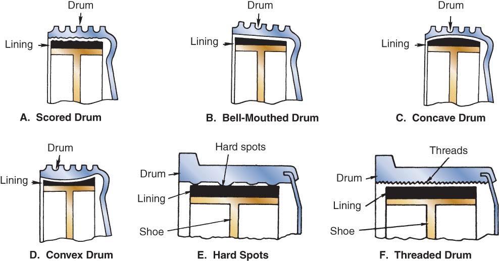
51 Drum wear conditions
52 Tech Tip Servo brake replacement shoes usually have different lining thicknesses. In most cases, the shoe with the thicker lining should be installed in the secondary shoe position facing the rear of the vehicle.
53 Shop Talk Never paint the outside of the drum. Paint will act as an insulator and slow heat dissipation. The heat absorbed by the drum during braking must be dissipated to the atmosphere around the drum. Overheated brakes result in brake fade!

54 Hydraulic disc brake assembly

55 Cutaway view of a hydraulic disc brake assembly
56 CAUTION Many OEMs recommend removing the brake hose or supporting the caliper when disassembling a disc brake assembly, especially on ABS. Never force the piston inboard without at least opening the bleed screw because contaminants tend to collect in the caliper bore. When the piston is forced inward, this dirt can be forced back to the master cylinder. Also, any sludge in the master cylinder is disturbed. Foreign material half the width of a human hair has been known to render ABS inoperative. It helps to rotate the caliper, so that the bleed screw position is facing downward helping to evacuate dirt.
57 CAUTION In cases where only the brake pads are to be replaced the caliper does not need to be hydraulically disconnected. Make sure that when the caliper assembly is separated, it is not allowed to hang by the brake hoses that can internally damage the hose.

58 Components of a hydraulically actuated, two-piston caliper assembly
59 Shop Talk When axial or radial runout specifications are provided by OEMs, they are expressed in total indicated runout (TIR). TIR is calculated by adding the most positive to the most negative reading through one complete revolution when using a dial indicator. For instance, if, after zeroing the dial indicator, a maximum positive reading of inch ( mm) and maximum negative reading of inch ( mm) occurs through one rotation, perform the following calculation to obtain the TIR: inch inch = inch ( mm) TIR
60 Shop Talk Excessive rotor runout or wobble increases pedal travel because the condition opens up the caliper piston and can cause pedal pulsation and chatter when the brakes are applied.

61 Typical truck hydraulic brake line circuit routing
62 CAUTION Never clamp brake hoses off with Vise-Grip or locking pliers. The result will be internal damage of the hose and premature failure.
 Remove the lock clip from the chassis bracket; and")
63 Brake hose replacement. (A) Remove the lock clip from the chassis bracket; and (B) disconnect the female end first.

64 Two common types of line flares and their seats

65 (A) Anvil folds tubing; and (B) cone performs second fold and doubles seat thickness.

66 Manual brake bleeding technique

67 Pressure bleeder

68 Location of ABS components on a 4S/4M small truck or school bus chassis
 front and")
69 Typical ABS wheel sensors: (A) front and (B) rear.

70 ABS operation: potential brake lock condition

71 Typical ABS hydraulic control unit
72 ABS OPERATION Wheel speed sensors continuously input wheel speed data to the ABS ECU. The system ECU monitors individual wheel speed data and compares it with average wheel speed. During braking, when the ECU senses that a high rate of wheel deceleration is occurring in a wheel, the modulator solenoid for the wheel first functions not to increase hydraulic pressure to the affected wheel.
73 System Redundancy In the event of a system failure, hydraulic ABS is required to default to normal, that is, non-abs, hydraulic braking. Should a single wheel speed sensor fail, ABS electronics will alert the driver to the fact that an ABS malfunction has occurred and operate the system in partial ABS mode. Systems are designed with a threshold of ABS failure fields that, once exceeded, results in defaulting to non- ABS operation. This is known as full redundancy operation.
74 CVSA OOS Commercial Vehicle Safety Alliance (CVSA) out of service (OOS) standards are not maintenance standards. They define the point at which highway equipment becomes dangerous to operate. OOS are used to issue citations during safety inspections.
75 Summary Hydraulic brakes tend to be used only on lighterduty highway trucks and off-highway applications. Hydraulic brakes are based on a principle that a liquid does not compress. Pressure applied to one portion of the circuit is transmitted equally to all parts of the circuit.
76 Summary In hydraulic braking systems, the mechanical force of the driver stepping on the brake pedal is converted to hydraulic pressure usually assisted by some type of power boost. At the wheel, the hydraulic force is once again changed back into the mechanical force required to brake the truck.
77 Summary Drum brakes can be servo, in which the action of one shoe is governed by input from the other, or non-servo, in which the shoes are separately anchored. Hydraulic disc brakes can be of the fixed caliper or floating/sliding caliper type.
78 Summary When the brake pedal is depressed, the master cylinder forces brake fluid to the calipers or wheel cylinders, changing mechanical force into hydraulic pressure; the wheel cylinders and calipers change hydraulic pressure back into mechanical force, braking the vehicle.
79 Summary Pressure differential valves, metering valves, proportioning valves, combination valves, and load proportioning valves are all operational components of a hydraulic brake system. In hydraulic brake systems, a hydraulic power booster is used to assist the master cylinder in applying the brakes. This means that the mechanical force applied by the driver s boot is amplified hydraulically.
80 Summary Some Class 6 and older Class 7 trucks are equipped with air-over-hydraulic brake systems. This combines some of the advantages of air and hydraulic brake systems. A hydraulic ABS is designed to modulate hydraulic application pressures to the wheel cylinders to permit maximum braking force without locking the wheels.
81 Summary A typical hydraulic ABS consists of wheel speed sensors, an electronic control module, and a modulator assembly. Hydraulic ABS is capable of modulation cycles at up to 15 times per second. All hydraulic ABS are required to default to full redundancy mode in the event of a complete system failure. Some systems permit operation in partial ABS in the event of subsection failure.
SECTION 4A HYDRAULIC BRAKES
 SECTION 4A HYDRAULIC BRAKES CAUTION: Disconnect the negative battery cable before removing or installing any electrical unit or when a tool or equipment could easily come in contact with exposed electrical
Brake System Operation
 Brake System Brake System Operation Donald Jones Brookhaven College Master cylinder Brake lines Hydraulic valves Disc brakes Drum brakes Power assist unit Parking brake Antilock system Brake System Functions
BRAKE SYSTEM Return To Main Table of Contents
 BRAKE SYSTEM Return To Main Table of Contents GENERAL... 2 BRAKE PEDAL... 10 MASTER CYLINDER... 13 BRAKE BOOSTER... 16 BRAKE LINE... 18 PROPORTIONING VALVE... 19 FRONT DISC BRAKE... 20 REAR DRUM BRAKE...
Brake Systems. Introduction
 Brake Systems Figure 1. A Typical Brake System Introduction The brake system (Figure 1) is designed to slow and halt the motion of a vehicle. To do that, various components within a hydraulic brake system
Brake System Fundamentals Chapter 71 Name Date Period
 Brake System Fundamentals Chapter 71 Name Date Period Basic Brake System Matching 1. Metal tubing and rubber hose that transmit pressure to the wheel brake assemblies. 2. Mechanical system for applying
DESCRIPTION & OPERATION
 DESCRIPTION & OPERATION BRAKE BOOSTER Delco-Moraine Single Diaphragm A combined vacuum-hydraulic unit which uses a combination of intake manifold vacuum and atmospheric pressure to provide power assist.
Parking brake Mechanical brake acting on rear wheels
 11 Brake System 11.1 General SPECIFICATIONS EJTC0010 Master cylinder Type Tandem type I.D. mm(in.) 20.64 mm (0.813 in.) Fluid level warning sensor Provided Brake booster Type Vacuum Boosting ratio 4.0
A proportioning valve is used to regulate brake pressure between front and rear brakes. Rear brakes on all models are self-adjusting.
 Page 1 of 21 ARTICLE BEGINNING DESCRIPTION & OPERATION WARNING: For warnings and procedures regarding vehicles equipped with Anti- Lock Brake Systems (ABS), see ANTI-LOCK BRAKE SYSTEM article in the BRAKES
1. General Description
 General Description 1. General Description A: SPECIFICATION Front disc brake Rear disc brake Master cylinder Brake booster Brake line Model Other models WRX MT WRX AT STi Size 15 inch type 16 inch type
SECTION 4A BRAKE SYSTEM TABLE OF CONTENTS
 SECTION 4A BRAKE SYSTEM TABLE OF CONTENTS Description and Operation... 4A-2 Braking System Testing... 4A-2 Hydraulic Brake System... 4A-2 Brake Pedal... 4A-2 Master Cylinder... 4A-2 Brake Booster... 4A-3
1999 Toyota RAV BRAKES Disc & Drum - Trucks & Vans
 DESCRIPTION & OPERATION 1999-2000 BRAKES Disc & Drum - Trucks & Vans WARNING: For warnings and procedures regarding vehicles equipped with Anti-Lock Brake Systems (ABS), see appropriate ANTI-LOCK article.
Self Adjusting Disc Brakes
 Disc Brakes Four advantages of Disc Brakes to Drum Brakes 1) Resistance to heat fade 2) Resistance to water fade 3) Less of a tendency to pull 4) Automatically adjust to lining wear Self Adjusting Disc
Brake System Diagnosis and Service
 AUMT 1310 - Brake System Diagnosis and Brake System Inspection Brake System Diagnosis and Donald Jones Brookhaven College Road test Hydraulic system Leaks Fluid condition Disc brakes Rotors and pads Drum
FUNDAMENTAL PRINCIPLES
 FUNDAMENTAL PRINCIPLES Fundamental Principles The most important safety feature of an automobile is its brake system. The ability of a braking system to provide safe, repeatable stopping is the key to
Hydro-Max Hydraulic Brake Booster and Master Cylinder. Technical Manual
 Hydro-Max Hydraulic Brake Booster and Master Cylinder Technical Manual * 5+0 Important Service Notes The information in this publication was current at the time of printing. The information presented in
Auto Fundamentals: brakes
 1 of 38 29/09/2006 13:27 Auto Fundamentals: brakes After studying this chapter, you will be able to: Identify the basic parts of the brake hydraulic system Describe the principles used for brake hydraulic
BRAKE SYSTEM Article Text 1996 Toyota RAV4 For Copyright 1998 Mitchell Repair Information Company, LLC Wednesday, September 13, :30PM
 Article Text ARTICLE BEGINNING 1996 BRAKES Toyota - Disc & Drum RAV4 * PLEASE READ THIS FIRST * WARNING: For warnings and procedures regarding vehicles equipped with Anti-Lock Brake Systems (ABS), see
C. Brake pads Replaceable friction surfaces that are forced against the rotor by the caliper piston.
 BRAKES UNIT 1: INTRODUCTION TO BRAKE SYSTEMS LESSON 1: FUNDAMENTAL PRINCIPLES OF BRAKE SYSTEMS I. Terms and definitions A. Brake fading Loss of brakes, usually due to heat. B. Brake lining Material mounted
Copyright 1998 Inter-Industry Conference On Auto Collision Repair v.4.0
 Uniform Procedures For Collision Repair BR11 Brakes 1. Description This procedure describes repair, replacement, and inspection requirements for collisiondamaged brake systems. 2. Purpose The purpose of
BRAKE SYSTEM GENERAL... 2 BRAKE PEDAL MASTER CYLINDER BRAKE BOOSTER BRAKE LINE PROPORTIONING VALVE... 19
 BRAKE SYSTEM Return To Main Table of Contents GENERAL... 2 BRAKE PEDAL... 11 MASTER CYLINDER... 13 BRAKE BOOSTER... 16 BRAKE LINE... 18 PROPORTIONING VALVE... 19 FRONT DISC BRAKE... 20 REAR DISC BRAKE...
Dura Force Disc Brake System Service Manual
 TS 20809_a 3501 Shotwell Drive ISO/TS 16949:2002 Registered (PH): 937.743.8125 Franklin, OH 45005 www.waltheremc.com (FX): 937.743.8232 Table of Contents General Description 1 3 Fastener Torque Chart 4
BRAKES 5-1 BRAKES CONTENTS
 PL BRAKES 5-1 BRAKES CONTENTS page ANTILOCK BRAKE SYSTEM TEVES MARK 20. 69 BASE BRAKE SYSTEM... 2 page GENERAL INFORMATION... 1 GENERAL INFORMATION page GENERAL INFORMATION BASE BRAKE SYSTEM DESCRIPTION...
2012 MKT Workshop Manual. REMOVAL AND INSTALLATION Procedure revision date: 06/13/2011
 SECTION 205-05: Rear Drive Halfshafts REMOVAL AND INSTALLATION Procedure revision date: 06/13/2011 Halfshaft Special Tool(s) Axle Seal Protector 205-816 Front Hub Remover 205-D070 (D93P-1175-B) or equivalent
BRAKE SYSTEM Nissan 240SX DESCRIPTION BRAKE BLEEDING * PLEASE READ FIRST * BLEEDING PROCEDURES ADJUSTMENTS BRAKE PEDAL HEIGHT SPECS TABLE
 BRAKE SYSTEM 1990 Nissan 240SX 1990 BRAKE SYSTEMS Nissan Disc & Drum Axxess, Maxima, Pathfinder, Pickup, Pulsar NX, Sentra, Stanza, 240SX, 300ZX DESCRIPTION All brake systems are hydraulically operated
Chapter 33 Fundamentals of Hydraulic and Air-Over-Hydraulic Braking Systems
 Chapter 33 Fundamentals of Hydraulic and Air-Over-Hydraulic Braking Systems Introduction Vehicle s braking system must meet the following requirements: To adequately and safely reduce a vehicle s speed,
Class 5 to 7 Truck and Bus Hydraulic Brake System
 Class 5 to 7 Truck and Bus Hydraulic Brake System Diagnostic Guide 2nd Edition www.bosch.us Important Service tes The information in this publication was current at the time of printing. The information
12. FRONT WHEEL/FRONT BRAKE/
 12 4.5kgm 0.9kg-m 4.5kg-m 12-0 SERVICE INFORMATION... 12-1 HYDRAULIC BRAKE... 12-10 TROUBLESHOOTING... 12-2 FRONT SHOCK ABSORBER... 12-16 FRONT WHEEL... 12-3 STEERING HANDLEBAR... 12-19 FRONT BRAKE...
BRAKE SYSTEM Toyota Celica DESCRIPTION DRUM BRAKES ADJUSTMENTS BRAKE PEDAL HEIGHT ADJUSTMENTS BRAKE PEDAL FREE PLAY ADJUSTMENTS
 BRAKE SYSTEM 1988 Toyota Celica 1988-89 BRAKES Toyota Celica, Corolla, MR2, Tercel DESCRIPTION The hydraulic brake system uses a tandem master cylinder with a vacuum power assist servo. MR2 and some Celica
Volkswagen New Beetle Brake System ABS, ABS/EDL 45 Anti-lock Brake System (ABS) (Page GR-45)
 (Page GR-45)") 45 Anti-lock Brake System (ABS) (Page GR-45) Anti-lock brake system (ABS) and anti-lock brake system with electronic differential lock (ABS/EDL) ITT Mark 20 IE Differences between ABS ITT Mark 20 IE and
45 Anti-lock Brake System (ABS) (Page GR-45) Anti-lock brake system (ABS) and anti-lock brake system with electronic differential lock (ABS/EDL) ITT Mark 20 IE Differences between ABS ITT Mark 20 IE and
COASTAL BEND COLLEGE AUTOMOTIVE TECHNOLOGY SYLLABUS (rev. Fall 2012)
") COASTAL BEND COLLEGE AUTOMOTIVE TECHNOLOGY SYLLABUS (rev. Fall 2012) AUMT 1310: Automotive Brake Systems SEMESTER HOURS: 3 TEXTBOOK Automotive Technology A systems Approach COURSE DESCRIPTION; Operation
COASTAL BEND COLLEGE AUTOMOTIVE TECHNOLOGY SYLLABUS (rev. Fall 2012) AUMT 1310: Automotive Brake Systems SEMESTER HOURS: 3 TEXTBOOK Automotive Technology A systems Approach COURSE DESCRIPTION; Operation
A. Adapter A metal component that fastens the caliper to the knuckle. Some brake systems do not use adapters.
 BRAKES UNIT 5: DISC BRAKE DIAGNOSIS AND REPAIR LESSON 3: SERVICE DISC BRAKE CALIPERS I. Terms and definitions A. Adapter A metal component that fastens the caliper to the knuckle. Some brake systems do
CAUTION. 2. Remove the wheel cover or nut covers, as required. Remove the wheel and tire assembly.
 Стр. 1 из 16 REAR DRUM BRAKES CAUTION Brake shoes may contain asbestos, which has been determined to be a cancer causing agent. Never clean the brake surfaces with compressed air! Avoid inhaling any dust
MASTER CYLINDER. Section 2. Lesson Objectives
 MASTER CYLINDER Lesson Objectives 1. Explain the difference between conventional and diagonal split piping system and their application. 2. Describe the function of the compensating port of the master
REMOVAL & INSTALLATION
 REMOVAL & INSTALLATION FRONT DISC BRAKE PADS 1. Raise and support front of vehicle. Remove wheels. Remove caliper bolt and brakeline bracket bolts. Pivot caliper aside. Remove pads and pad shim. Remove
Trailer Brake System Bleeding Procedure:
 Trailer Brake System Bleeding Procedure: The procedure immediately below assumes that a power bleeder will be used. Two people will be required to bleed the brakes if bleeding is to be performed conventionally
INSTALLATION INSTRUCTIONS
 INSTALLATION INSTRUCTIONS PERFORMANCE AT THE WHEELS KITS W156-6 & W156-7 1965-74 MOPAR B & E BODY Thank you for choosing STAINLESS STEEL BRAKES CORPORATION for your braking needs. Pleases take the time
REMOVAL & INSTALLATION
 REMOVAL & INSTALLATION REAR BRAKE CALIPER NOTE: For rear disc pad removal and installation, DO NOT disconnect brake hose from caliper (wire aside). Replace all pads on an axle if wear indicator on any
INSTALLATION INSTRUCTIONS
 INSTALLATION INSTRUCTIONS REAR DISC BRAKE CONVERSION KIT A126-3 1988-98 CHEVY K1500 4WD 10" DRUMS Thank you for choosing STAINLESS STEEL BRAKES CORPORATION for your braking needs. Pleases take the time
GM Full-Size Trucks Repair Information
 . 1 of 12 12/26/2009 10:47 AM GM Full-Size Trucks 1988-1998 Repair Information Brake Shoes INSPECTION REMOVAL & INSTALLATION ADJUSTMENT INSPECTION 1. 2. 3. 4. 5. Raise and support the rear end on jackstands.
Modern Auto Tech Study Guide Chapters 71 & 73 Pages Brake Systems 49 Points. Automotive Service
 Modern Auto Tech Study Guide Chapters 71 & 73 Pages 1369 1444 Brake Systems 49 Points 1. Automotive systems use to stop, slow or to hold the wheels from turning. Brake, Friction Brake, Fraction Brake,
INSTALLATION INSTRUCTIONS
 INSTALLATION INSTRUCTIONS REAR DISC BRAKE CONVERSION KITS A112, A112-1 & A112-93 1979-93 FORD MUSTANG with 7.5" & 8.8" AXLES Thank you for choosing STAINLESS STEEL BRAKES CORPORATION for your braking needs.
INSTALLATION INSTRUCTIONS
 INSTALLATION INSTRUCTIONS REAR DISC CONVERSION KIT A128-4 1997-2004 JEEP WRANGLER (TJ) WITH DANA 44 AXLES (non-abs) Thank you for choosing STAINLESS STEEL BRAKES for your braking needs. Pleases take the
Property of American Airlines
 CHAPTER 3 TABLE OF CONTENTS CHAPTER/SECTION PAGE OVERHAUL I. RECOMMENDED OVERHAUL PERIODS 3-1 1 A. GENERAL... 1 B. HYDRAULIC PUMP... 1 C. DISC BRAKE CALIPERS... 1 D. BRAKE BOOSTER PUMP... 1 E. MASTER CYLINDER...
2000 Saturn LS2. Fig. 2: Identifying Self-Adjuster Components (Drum Brakes) Courtesy of GENERAL MOTORS CORP. WHEEL CYLINDERS
 Courtesy of GENERAL MOTORS CORP. WHEEL CYLINDERS") Fig. 2: Identifying Self-Adjuster Components (Drum Brakes) WHEEL CYLINDERS Raise and support vehicle. Remove brake shoes. See REAR BRAKE SHOES. Disconnect brake pipe from wheel cylinder. See Fig. 3. Remove
Fig. 2: Identifying Self-Adjuster Components (Drum Brakes) WHEEL CYLINDERS Raise and support vehicle. Remove brake shoes. See REAR BRAKE SHOES. Disconnect brake pipe from wheel cylinder. See Fig. 3. Remove
Brake System H TX, H2.0TXS [B475]; H TX [B466] Safety Precautions Maintenance and Repair
![Brake System H TX, H2.0TXS [B475]; H TX [B466] Safety Precautions Maintenance and Repair](/thumbs/86/93834005.jpg "Brake System H TX, H2.0TXS [B475]; H TX [B466] Safety Precautions Maintenance and Repair") HMM180001 Brake System H1.5-1.8TX, H2.0TXS [B475]; H2.5-3.5TX [B466] Safety Precautions Maintenance and Repair When lifting parts or assemblies, make sure all slings, chains, or cables are correctly fastened,
HMM180001 Brake System H1.5-1.8TX, H2.0TXS [B475]; H2.5-3.5TX [B466] Safety Precautions Maintenance and Repair When lifting parts or assemblies, make sure all slings, chains, or cables are correctly fastened,
CAUTION. Hydraulic Brakes. Braking Systems - Hydraulic
 Hydraulic Brakes The hydraulic brakes on your trailer are much like those on your automobile or light truck. The hydraulic fluid from a master cylinder or actuation system is used to actuate the wheel
ILLUSTRATION ILLUSTRATION
 ILLUSTRATION ILLUSTRATION REMOVAL 1. DISABLE BRAKE CONTROL (a) Wait at least 2 minutes after the power switch off. When the brake pedal is depressed or the door courtesy switch is turned on even if the
ANTI-LOCK BRAKE SYSTEM - REAR WHEEL
 ANTI-LOCK BRAKE SYSTEM - REAR WHEEL 1994 Nissan Pickup 1994 BRAKES Nissan - Rear Anti-Lock Pathfinder, Pickup DESCRIPTION In 2WD mode, Rear Anti-Lock Brake System (RABS) helps the driver to maintain steering
Installation Instructions
 Preparing your vehicle to install your brake system upgrade 1. Rack the vehicle. 2. If you don t have a rack, then you must take extra safety precautions. 3. Choose a firmly packed and level ground to
INSTALLATION INSTRUCTIONS
 INSTALLATION INSTRUCTIONS REAR DISC CONVERSION KIT A128 1990-1995 JEEP WRANGLER (YJ) WITH DANA 35 AXLES (non-abs) Thank you for choosing STAINLESS STEEL BRAKES CORPORATION for your braking needs. Pleases
Troubleshooting, Service Tips, And Major Improvements For Hydrostatic Transmissions (Special Edition){3200}
{3200}") Page 1 of 75 Troubleshooting, Service Tips, And Major Improvements For Hydrostatic Transmissions (Special Edition){3200} 943, 953, 963, 973 Loaders Introduction The hydrostatic transmissions used in 943,
Page 1 of 75 Troubleshooting, Service Tips, And Major Improvements For Hydrostatic Transmissions (Special Edition){3200} 943, 953, 963, 973 Loaders Introduction The hydrostatic transmissions used in 943,
Installation Guide. Installing the FRK Hydraulic Compact Unit (HCU) with Parking Brake Valve on International School Buses
 with Parking Brake Valve on International School Buses") Revised 09-18 Installation Guide Revised 1 Technical 09-18 Bulletin Installing the FRK 08-10086 Hydraulic Compact Unit (HCU) with Parking Brake Valve on International School Buses Hazard Alert Messages
Revised 09-18 Installation Guide Revised 1 Technical 09-18 Bulletin Installing the FRK 08-10086 Hydraulic Compact Unit (HCU) with Parking Brake Valve on International School Buses Hazard Alert Messages
INSTALLATION INSTRUCTIONS
 INSTALLATION INSTRUCTIONS BIG ROTOR / CALIPER RELOCATION REAR KIT SUM-BK1423 1999-2009 GM 1/2 Ton Trucks & SUVs Thank you for choosing SUMMIT RACING for your braking needs. Pleases take the time to read
12. FRONT WHEEL/FRONT BRAKE/
 12 12 12-0 SERVICE INFORMATION... 12-1 FRONT BRAKE... 12-7 TROUBLESHOOTING... 12-2 FRONT SHOCK ABSORBER... 12-18 STEERING HANDLEBAR... 12-3 FRONT FORK... 12-21 FRONT WHEEL... 12-4 SERVICE INFORMATION GENERAL
GENERAL PROCEDURES. Component Bleeding. Master Cylinder Priming In-Vehicle or Bench
 206-00-1 Brake System General Information 206-00-1 GENERAL PROCEDURES Component Bleeding Special Tool(s) Worldwide Diagnostic System (WDS) 418-F224, New Generation STAR (NGS) Tester 418-F052, or equivalent
BASIC BRAKE SYSTEM GROUP 35A 35A-1 CONTENTS GENERAL DESCRIPTION... 35A-3 BASIC BRAKE SYSTEM DIAGNOSIS 35A-6
 35A-1 GROUP 35A BASIC BRAKE SYSTEM CONTENTS GENERAL DESCRIPTION......... 35A-3 DIAGNOSIS 35A-6 INTRODUCTION..................... 35A-6 DIAGNOSTIC TROUBLESHOOTING STRATEGY......................... 35A-6
INSTALLATION INSTRUCTIONS
 INSTALLATION INSTRUCTIONS PERFORMANCE AT THE WHEELS KIT W120-22, W120-23 1964 1/2-69 MUSTANG Thank you for choosing STAINLESS STEEL BRAKES CORPORATION for your braking needs. Pleases take the time to read
DESCRIPTION & OPERATION
 2004 BRAKES Disc - TSX DESCRIPTION & OPERATION WARNING: DO NOT use air pressure or a dry brush to clean brake assemblies. Avoid breathing brake dust. Use OSHA-approved vacuum cleaner for cleaning and collecting
Braking System Layout
 The Braking System The energy used to accelerate or move a vehicle from rest to a certain speed is called Kinetic i (moving) energy. To slow the vehicle down, this kinetic energy must be converted or changed,
CHASSIS CONTENTS EXTERIOR PARTS 6-1 FRAME COVER 6-2 REAR FRAME COVER 6-4 FRONT WHEEL 6-6 FRONT BRAKE 6-10 HANDLEBARS 6-17 FRONT FORK 6-19
 CHASSIS CONTENTS EXTERIOR PARTS 6- FRAME COVER 6- REAR FRAME COVER 6-4 FRONT WHEEL 6-6 FRONT BRAKE 6-0 HANDLEBARS 6-7 FRONT FORK 6-9 STEERING 6-6 REAR WHEEL 6-3 REAR BRAKE 6-39 6 REAR SHOCK ABSORBER 6-43
Installation Guide. Installing the FRK Hydraulic Compact Unit (HCU) on International School Buses TP-0913 Issued 1 Technical Bulletin
 on International School Buses TP-0913 Issued 1 Technical Bulletin") Issued 12-08 Installation Guide Installing the FRK 08-10086 Hydraulic Compact Unit (HCU) on International School Buses Issued 1 Technical 12-08 Bulletin Hazard Alert Messages Read and observe all Warning
Issued 12-08 Installation Guide Installing the FRK 08-10086 Hydraulic Compact Unit (HCU) on International School Buses Issued 1 Technical 12-08 Bulletin Hazard Alert Messages Read and observe all Warning
ASE Practice Test A5 Brakes
 ASE Practice Test A5 Brakes Hydraulic System Diagnosis and Repair 1) A spongy brake pedal may be caused by: a. ABS Diagnostic Trouble Code set b. Frozen caliper piston c. Defective metering valve d. Air
INSTALLATION INSTRUCTIONS
 INSTALLATION INSTRUCTIONS REAR DISC CONVERSION KIT A126-2 1988-98 C1500 2WD 10" REAR DRUM Thank you for choosing STAINLESS STEEL BRAKES CORPORATION for your braking needs. Pleases take the time to read
FUNDAMENTAL PRINCIPLES
 Section 1 FUNDAMENTAL PRINCIPLES Lesson Objectives 1. Describe the cycle of heat as it applies to automotive brakes. 2. Explain the effect of heat transfer as it relates to brake fade. 3. Describe how
INSTALLATION INSTRUCTIONS
 INSTALLATION INSTRUCTIONS REAR DISC BRAKE CONVERSION KIT A158 1994-97 Dodge Ram 1500 (2WD & 4WD) and REAR DISC BRAKE CONVERSION KIT A158-1 1998-01 Dodge Ram 1500 (2WD & 4WD) Thank you for choosing STAINLESS
SECTION 4A HYDRAULIC BRAKES
 SECTION 4A HYDRAULIC BRAKES Caution: Disconnect the negative battery cable before removing or installing any electrical unit or when a tool or equipment could easily come in contact with exposed electrical
2010 Toyota Prius Repair Manual
 REMOVAL 1. DISABLE BRAKE CONTROL (a) Wait at least 2 minutes after the power switch off. NOTICE: When the brake pedal is depressed or the door courtesy switch is turned on even if the power switch is off,
ALLDATA Online Saturn L200 L4-2.2L VIN F - Base Brake Bleeding. Base Brake Bleeding
 Page 1 of 9 Base Brake Bleeding BASE BRAKE BLEEDING TOOLS REQUIRED J-439l5 Brake Bleed Adapter J29532 Pressure Bleeder MANUAL BLEEDING NOTICE: Brake fluid is corrosive to painted surfaces. Take care not
Installing FRK and FRK Hydraulic Compact Unit (HCU) on Navistar Straight Trucks
 on Navistar Straight Trucks") Revised 09-18 Technical Bulletin Installing FRK 09-10091 and FRK 09-10092 Hydraulic Compact Unit (HCU) on Navistar Straight Trucks Revised 1 Technical 09-18 Bulletin Hazard Alert Messages Read and observe
Revised 09-18 Technical Bulletin Installing FRK 09-10091 and FRK 09-10092 Hydraulic Compact Unit (HCU) on Navistar Straight Trucks Revised 1 Technical 09-18 Bulletin Hazard Alert Messages Read and observe
Hydraulic Master Cylinders
 Hydraulic Master Cylinders flange mount and side mount, straight-bore and two-stage cylinders Hydraulic Cylinders for Mobile and Industrial Applications Why choose MICO? MICO, Incorporated designs, manufactures
ASSEMBLY INSTRUCTIONS FOR DYNALITE DRAG RACE FRONT HUB KIT WITH DIAMETER SOLID ROTOR PINTO / MUSTANG II
 ASSEMBLY INSTRUCTIONS FOR DYNALITE DRAG RACE FRONT HUB KIT WITH 0.75 DIAMETER SOLID ROTOR 97-978 PINTO / MUSTANG II (FIVE LUG CONFIGURATION ONLY)* PART NUMBER GROUP 0-03-B DISC BRAKES SHOULD ONLY BE INSTALLED
INSTALLATION INSTRUCTIONS
 INSTALLATION INSTRUCTIONS BIG ROTOR / CALIPER RELOCATION FRONT KITS SUM-BK1422, BK1423, BK1424 1999-2006 GM 1/2 Ton Trucks & SUVs Thank you for choosing SUMMIT RACING for your braking needs. Pleases take
A 1 SERVICE SPECIFICATIONS
 A1 A2 Clutch CLUTCH Specifications Pedal height (from asphalt sheet) Release point (from pedal stroke end position) Push rod play at pedal top Pedal freeplay Disc rivet head depth Disc runout Diaphragm
CHASSIS CONTENTS EXTERIOR PARTS 6-1 FRONT WHEEL 6-2 FRONT BRAKE 6-6 HANDLEBARS 6-12 REAR WHEEL 6-30 REAR BRAKE 6-34 REAR SHOCK ABSORBER 6-36
 CHASSIS CONTENTS EXTERIOR PARTS 6-1 FRONT WHEEL 6-2 FRONT BRAKE 6-6 HANDLEBARS 6-12 FRONT FORK ( ) 6-14 FRONT FORK ( ) 6-20 STEERING 6-27 REAR WHEEL 6-30 REAR BRAKE 6-34 REAR SHOCK ABSORBER 6-36 6 SWING
M-2300-T 6-Piston Mustang Brake Kit INSTALLATION INSTRUCTIONS
 Please visit www.fordracingparts.com for the most current instruction information!!! PLEASE READ ALL OF THE FOLLOWING INSTRUCTIONS CAREFULLY PRIOR TO INSTALLATION. AT ANY TIME YOU DO NOT UNDERSTAND THE
INSTALLATION INSTRUCTIONS
 INSTALLATION INSTRUCTIONS INSTRUCTION FOR ASSEMBLY OF JEEP CJ SERIES W/AMC 20 REAR AXLES, 5 x 5-1/2" BOLT CIRCLE WITH A130-1 FULL FLOATING AXLE OR A130-2 (1 PIECE AXLE) Thank you for choosing STAINLESS
Angle Mounted Master Cylinder Bleeding Procedure
 Angle Mounted Master Cylinder Bleeding Procedure All angle-mounted master cylinders. Unable to obtain a firm brake pedal when bleeding master cylinder on vehicle Cause: Air trapped in the upper end of
MECA0063 : Braking systems
 MECA0063 : Braking systems Pierre Duysinx Research Center in Sustainable Automotive Technologies of University of Liege Academic Year 2018-2019 1 Bibliography T. Gillespie. «Fundamentals of vehicle Dynamics»,
Hydraulic Brake Systems
 Hydraulic Brake Systems Mondel Hydraulic Brake Systems Instruction Manual Part Number: 560041-R0 February 2006 Copyright 2006 Magnetek Material Handling Installation and Maintenance Instructions Hydraulic
INSTALLATION INSTRUCTIONS
 INSTALLATION INSTRUCTIONS REAR DISC BRAKE CONVERSION KIT A125-3 1965-72 GM A-BODY 10 & 12 BOLT AXLES Thank you for choosing STAINLESS STEEL BRAKES CORPORATION for your braking needs. Pleases take the time
Your Brakes. Fundamentals of Braking
 B U S S E R V I C E, I N C. Your Brakes Fundamentals of Braking There are a variety of mechanical forces and physical components that make up the braking system of your coach. The forces that effect your
INSTALLATION INSTRUCTIONS
 INSTALLATION INSTRUCTIONS DISC BRAKE CONVERSION KITS A121-1, A121-2, A121-3, A121-4 1967-69 Ford & Mercury Thank you for choosing STAINLESS STEEL BRAKES CORPORATION for your braking needs. Pleases take
This file is available for free download at
 This file is available for free download at http://www.iluvmyrx7.com This file is fully text-searchable select Edit and Find and type in what you re looking for. This file is intended more for online viewing
GROUP 35A 35A-1 CONTENTS GENERAL DESCRIPTION... 35A-3 BASIC BRAKE SYSTEM DIAGNOSIS 35A-6 HYDRAULIC BRAKE BOOSTER (HBB) DIAGNOSIS...
 DIAGNOSIS...") 35A-1 GROUP 35A CONTENTS GENERAL DESCRIPTION......... 35A-3 DIAGNOSIS 35A-6 INTRODUCTION..................... 35A-6 DIAGNOSTIC TROUBLESHOOTING STRATEGY......................... 35A-6 SYMPTOM CHART...................
35A-1 GROUP 35A CONTENTS GENERAL DESCRIPTION......... 35A-3 DIAGNOSIS 35A-6 INTRODUCTION..................... 35A-6 DIAGNOSTIC TROUBLESHOOTING STRATEGY......................... 35A-6 SYMPTOM CHART...................
SUSPENSION 2-1 SUSPENSION TABLE OF CONTENTS
 DN SUSPENSION 2-1 SUSPENSION TABLE OF CONTENTS page ALIGNMENT... 1 FRONT SUSPENSION - 4x2... 6 page FRONT SUSPENSION - 4x4... 14 REAR SUSPENSION... 23 ALIGNMENT TABLE OF CONTENTS page AND OPERATION WHEEL
SERVICING FRONT BRAKE CALIPERS BY PAUL WEISSLER Illustrations by Russell J. von Sauers and Ron Carboni Published on: June 12, 2001
 1 of 5 29/08/2006 2:22 PM SAVE THIS EMAIL THIS Close SERVICING FRONT BRAKE CALIPERS BY PAUL WEISSLER Illustrations by Russell J. von Sauers and Ron Carboni Published on: June 12, 2001 Brake lights in front
Hydraulic Brake System and Trailer Brake Inspection Procedure
 Summary Created: April 26, 2012 Revised: April 27, 2016 Revised: April 27, 2017 This Inspection Bulletin describes inspection procedures and operating information for commercial motor vehicles and trailers
BRAKE SYSTEM Article Text 1992 Mitsubishi Mirage For a a a a a Copyright 1998 Mitchell Repair Information Company, LLC Monday, April 01, :05AM
 Article Text ARTICLE BEGINNING 1992 BRAKES Chrysler Motors/Mitsubishi - Disc & Drum Chrysler Motors: Colt, Colt 200, Colt Vista, Ram-50, Stealth, Summit, Summit Wagon; Mitsubishi: Diamante, Eclipse, Expo/Expo
DISC BRAKE/DUAL MASTER CYLINDER CONVERSION. Tools, Equipment and Supplies Needed:
 Please take the time to read the enclosed instructions carefully. If you have any questions, call our Product Assistance personnel for clarification. It is important to note that these instructions contain
GENERAL DESCRIPTION BR 2
 BR1 BR2 GENERAL DESCRIPTION GENERAL DESCRIPTION 1. Care must be taken to replace each part properly as it could affect the performance of the brake system and result in a driving hazard. Replace the parts
w w w. h d o n l i n e s h o p. d e CHROME FRONT BRAKE MASTER CYLINDER KIT GENERAL INSTALLATION -J03735 REV Kit Number Models
 -J05 REV. 005-06- GENERAL Kit Number 58-D, 58-D Models CHROME FRONT BRAKE MASTER CYLINDER KIT These Chrome Master Cylinder Kits are designed to replace the original equipment front brake master cylinder
BRAKE SYSTEM SECTIONBR CONTENTS
 BRAKE SYSTEM SECTIONBR CONTENTS PRECAUTIONS...3 Supplemental Restraint System (SRS) AIR BAG and SEAT BELT PRE-TENSIONER...3 Precautions for Brake System...3 Wiring Diagrams and Trouble Diagnosis...4 PREPARATION...5
35-1 GROUP 35 SERVICE BRAKES CONTENTS BASIC BRAKE SYSTEM... 35A ANTI-LOCK BRAKING SYSTEM (ABS)... 35B TRACTION CONTROL SYSTEM (TCL)...
... 35B TRACTION CONTROL SYSTEM (TCL)...") 35-1 GROUP 35 SERVICE BRAKES CONTENTS.............................. 35A ANTI-LOCK BRAKING SYSTEM (ABS)................... 35B TRACTION CONTROL SYSTEM (TCL)................... 35C 35A-2 GROUP 35A BASIC
35-1 GROUP 35 SERVICE BRAKES CONTENTS.............................. 35A ANTI-LOCK BRAKING SYSTEM (ABS)................... 35B TRACTION CONTROL SYSTEM (TCL)................... 35C 35A-2 GROUP 35A BASIC
Webinar Series. APTA Bus Technical Maintenance Committee Webinar Series. Disc Brake Wheels On Inspection. Presents
 1 Webinar Series APTA Bus Technical Maintenance Committee Webinar Series Presents Disc Brake Wheels On Inspection January 28, 2015 2 Introduction Welcome to today s webinar in which we will cover a wheels
ASSEMBLY INSTRUCTIONS FOR WILWOOD FRONT D52 CALIPER KIT GM VEHICLES USING D52 CALIPER AND BRAKE PADS WITH 1.
 ASSEMBLY INSTRUCTIONS FOR WILWOOD FRONT D5 CALIPER KIT 1968-1996 GM VEHICLES USING D5 CALIPER AND BRAKE PADS WITH 1.8 THICK ROTORS PART NUMBER GROUP 10-1190 DISC BRAKES SHOULD ONLY BE INSTALLED BY SOMEONE
INSTALLATION INSTRUCTIONS R1 REAR CONVERSION KIT
 INSTALLATION INSTRUCTIONS R1 REAR CONVERSION KIT INSTRUCTION FOR ASSEMBLY OF JEEP CJ SERIES W/AMC 20 REAR AXLES, 5 x 5-1/2" BOLT CIRCLE WITH A130-4 FULL FLOATING AXLE OR A130-5 (1 PIECE AXLE) Thank you
SERVICE BRAKES GROUP 35A 35A-1 CONTENTS GENERAL DESCRIPTION... 35A-2 BRAKE PEDAL... 35A-22 BASIC BRAKE SYSTEM DIAGNOSIS 35A-3
 35A-1 GROUP 35A CONTENTS GENERAL DESCRIPTION 35A-2 BASIC BRAKE SYSTEM DIAGNOSIS 35A-3 INTRODUCTION TO BASIC BRAKE SYSTEM DIAGNOSIS 35A-3 BASIC BRAKE SYSTEM DIAGNOSTIC TROUBLESHOOTING STRATEGY 35A-3 SYMPTOM
INSTALLATION INSTRUCTIONS
 INSTALLATION INSTRUCTIONS REAR DISC BRAKE CONVERSION KIT A125-2 1955-70 FULL SIZE CHEVROLET Thank you for choosing STAINLESS STEEL BRAKES CORPORATION for your braking needs. Pleases take the time to read
18_25~~ VI ~.' ""'~. ~~ ft lb), f? 8-13 N m qj ~O..f9 ( kg-m. .0 ~J. I i~" C;Q () 0 ~,t) ~ ft lb), ~, ' ~.
, f? 8-13 N m qj ~O..f9 ( kg-m. .0 ~J. I i~ C;Q () 0 ~,t) ~ ft lb), ~, ' ~.") ~El:OlV:D.A. FRONT: 25-35 N m (2.5-3.5 kg-m, 18_25~~ REAR: 30-40 N m (3.0-4,0 kg-m VI ~.' ""'~. ~~ 22-29 ft lb), f? 8-13 N m qj ~O..f9 (0.8-1.3kg-m C;Q () 0 ~,t) ~ 1------ 6-9 ft lb),.0 ~J. I i~" ~, '
~El:OlV:D.A. FRONT: 25-35 N m (2.5-3.5 kg-m, 18_25~~ REAR: 30-40 N m (3.0-4,0 kg-m VI ~.' ""'~. ~~ 22-29 ft lb), f? 8-13 N m qj ~O..f9 (0.8-1.3kg-m C;Q () 0 ~,t) ~ 1------ 6-9 ft lb),.0 ~J. I i~" ~, '
BRAKES SERVICE BRAKES
 A GROUP 5 BRAKES CONTENTS DISC BRAKES (KELSEY HAYES),. 22 GENERAL INFORMATION 1 MASTER CYLINDERS 9-34 PARKING BRAKES 14 POWER BRAKES (BENDIX) 19 POWER BRAKES (BENDIX-Duo Diaphragm) 20 GENERAL INFORMATION