MINI SLIDE NEW. The last word in productivity
|
|
|
- Clinton Moore
- 5 years ago
- Views:
Transcription


1 The last word in productivity NEW
2
3 Contents Product overview Product range 4 Exceptional guideways The last word in productivity 5 Exceptional properties of the MS series MS 4 and MS 5 highest results in the smallest envelope 6 MS 4 and MS 5 high reliability due to reduced cage creeping 6 Exceptional properties of the MSQ series MSQ highest rigidity and precision 7 MSQ highest process stability due to elimination of cage creeping 8 Further important features and uses Precision at highest speed 9 Customer specific solutions 10 Scope of applications Precision within the smallest envelope 11 Accuracy Maximum performance through precision 12 Supporting structure Design of the supporting structure 13 Requirements of the mounting surfaces 13 Dimensioning and operational life Load capacity and operational life 14 Life expectancy 14 Life ecpectancy calculation 15 Technical Data MINI MS 4 16 MS 5 17 MSQ 7 18 MSQ 9 19 MSQ MSQ Handling, installation and lubrication Transport and storage 22 Handling and installation 22 Lubrication 22 Further information Ordering information 23 Free downloads of 2D and 3D drawings 23 3
4 Product overview Product range The MINI range covers six main sizes each available in different standard lengths. MS 4 MS 5 MSQ 7 MSQ 9 MSQ 12 MSQ 15 Page 16 Page 17 Page 18 Page 19 Page 20 Page 21 Sizes and strokes Rail width in mm System width in mm System height in mm Lengths in mm (without end pieces) Strokes in mm Perfomance parameters Maximum acceleration in m/s Maximum speed in m/s Preload no play no play no play no play no play no play Accuracy Page 12 Page 12 Page 12 Page 12 Page 12 Page 12 Dynamic load capacity Technical performance Cage centering Cage controly system Gothic arch profile Circular tracks /O-Geometry Mechanical stroke limiter (1) Technical details Rail, upper part, balls, screws resistant steel resistant steel resistant steel resistant steel resistant steel resistant steel Cage plastic plastic plastic plastic plastic plastic Pinion plastic plastic plastic plastic End parts plastic plastic plastic plastic Areas of application High vacuum in mbar (2) (4) Operating temperature in C (3) 40/+80 40/+80 40/ / / /+150 Short-term maximum temperature in C (3) (1) The mechanical stroke limiter of MINI assists installation and maintenance. In no event must it be used to limit the stroke during operation. (2) The vacuum compatibility relates only to the materials used. To use the slide in vacuum, air must be removed from all drilled and tapped holes and/or vented screws should be used. (Price upon request). (3) The standard lubrication covers a temperature range of -20 C to +100 C. For lubrication at other temperatures please consult SCHEEEBERGER. (4) Use in vacuum requires a special lubrication, details of which can be obtained from SCHNEEBERGER. 4

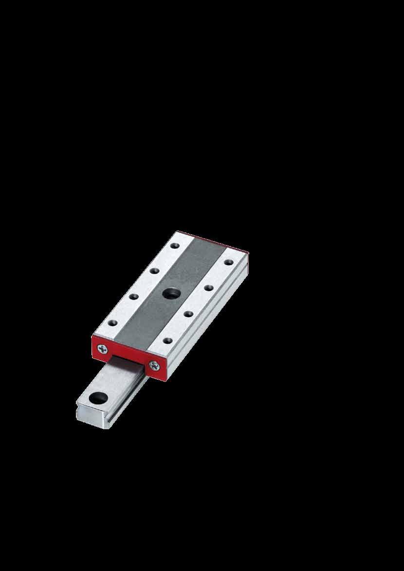
5 Exceptional guideways The last word in productivity Challenging applications demand exceptional guideways. MINI embodies the newest generation of miniature slides for extremely demanding applications. They are highly robust and reliable in every application due to their smooth performance, precision and long service lifetime. Dimensions in mm MINI Product range overview 5


6 Exceptional properties of the MS series MS 4 and MS 5 highest results in the smallest envelope The gothic arch profile of the MINI MS tracks permits loads that are more than ten times higher than a traditional 90 V-profile. Gothic arch profile 90 V-profile. Gothic arch profile, 90 V-profile Benefits of the gothic arch profile High load-carrying capacity in a compact design Maximum rigidity Low sensitivity to impacts Excellent damping behaviour Robust Low weight MS 4 and MS 5 high reliability due to reduced cage creeping MINI MS 4 and MS 5 employ a single-piece cage to counteract any cage creeping. An integrated cage-alignment system corrects any cage displacement. 6 MINI MS with single-pieced cage and cage alignment

7 Exceptional properties of the MSQ series MSQ highest rigidity and precision MINI MSQ employs four circular tracks/o-geometry. The O-Geometry (see figure) creates large contact surfaces. With 90 track displacement, MSQ achieves an uniform and high load capacity in all directions as well as hight moment-rigidity. MINI are preloaded and free of play. The high number of rolling elements provides high system rigidity and therefore highest precision is guaranteed. O-Geometry MINI MSQ with highest rigidity and precision Deformation (μm) profile gothic arch profile circular tracks of MSQ Force (N) Comparison of the rigidity of MINI size , with identical overall dimensions, but designed with different track profiles The benefits of an O-Geometry High load-carrying capacity with compact design Maximum rigidity Low sensitivity to impacts Excellent damping behaviour Robust Low weight 7

8 MSQ highest process stability due to elimination of cage creeping In applications using linear bearings, the cage moves freely with the axis motion. Nev ertheless, through uneven load distribution, high acceleration or insufficient rigidity or accuracy in the surrounding construction, the cage can become displaced from its central position. This cage-creep impairs the effectiveness of every application since the cage needs to be centered frequently with a cage correction stroke. This correction additionally requires power from the drive motor. The models MSQ 7, MSQ 9, MSQ 12 and MSQ 15 are equipped with a highly developed and robust cage control system. This eliminates cage-creep. The toothing system of the cage control system is incorporated directly into the carriage and rail. Cage and pinion are made of high-quality plastic. This compact and robust design, with a minimum number of integral components, ensures high reliability under all running conditions. MINI MSQ with incorporated toothing system in carriage and rail Benefits of the integrated cage control system No need for re-centering of the cage in applications with vertical installation, high accelerations or with uneven load distribution Neither the tolerances of the surrounding construction nor temperature differences lead to cage creep Reduced cycle times due to higher speed and acceleration Adjustment-free operation and therefore, more productive time High operational life 8

9 Further important features and uses Precision at highest speed Applications requiring high accelerations and duty cycles demand well thought out solutions. Through its unique design, MINI meets the requirements of mod ern equipment; high speeds, extreme accelerations and high frequency oscillations. MINI when speed counts 9

10 Customer-specific solutions SCHNEEBERGER s many years of experience in linear technology have gone into the concept and design of MINI. Due to its outstanding performance parameters, MINI sets a standard for quality in any application. MINI is designed for universal use. It can also be customized at the factory for specific customer requirements. SCHNEEBERGER offers, amongst other things, the following services. Services of SCHNEEBERGER Defined push force Special lubrication (vacuum, extreme temperature, etc.) Special packaging Customer-specific designs Customer-specific modifications 10

11 Scope of applications Precision within the smallest envelope MINI is used wherever high-precision and process reliability is required within a limited space. Through its unique advantages, MINI is especially suitable for the following applications: The most frequent application areas of MINI are: Biotechnology Laboratory automation Medical technology Metrology Micro automation Micro machining Nanotechnology Semiconductor industry Surface finishing Optical industry Robotics, pick & place Wire bonder: Minislide in action 11
12 Accuracy Maximum performance through precision The tolerance for the straightness of the stroke depends on the length of MINI. The following table gives the relevant maximum values. The measurements were carried out on a even surface in a free state condition. Straightness of travel Straightness of travel Parellelism of table over stroke; laterally over stroke; at top surfaces in middle position Length mm 3 µm 3 µm 12 µm mm 4 µm 4 µm 15 µm mm 5 µm 5 µm 18 µm Height tolerance: A: mm B 2 : mm A B 2 12

13 Suporting structure Design of the supporting structure MINI is a high-precision component. Accordingly, high demands are placed on the supporting structure to optimise the accuracies of the slide. For this reason, certain parameters must be strictly adhered to in the manufacture of the supporting structure. The flatness of the supporting surface in the transverse direction must be within 3μm The surface roughness should be N5 N7 (Ra-Values 0.4 to 1.6) The quality of the abbuting and supporting surfaces, as well as the rigidity of the supporting structure, must comply with the highest demands. If this is not the case, then push force, accuracy and operational life will be compromised. To ensure highest precision, it is recommended that the slides are mounted to a rigid, precisionmachined base. Supporting structures made of light metals cannot be made to fully comply with the required manufacturing accuracy and rigidity. Requirements for the mounting surfaces The measurements for the abbuting surface listed in the following table should be met to enable optimum alignment of the slide and simple installation. The following table provides information pertaining to the maximum permissible radii and heights of abbuting surface. The datum side of the carriage is opposite to the side marked with the part number. MS 4 MS 5 MSQ 7 MSQ 9 MSQ 12 MSQ 15 h 1max r 1max r 2max h r 2 h1 h2 r 1 Heights of abbuting surface and corner radii (mm) 13
14 Dimensioning and operational life Loading capacity and operational life The load ratings of MINI (see pages 16 21) are based on the specifications established by ISO and DIN for the calculation of rolling element bearings (DIN ISO 14728). The actual (equivalent) loading in relation to the dynamic load value C is important for the sizing and selection of MINI. The load carrying capacity C is the load with which a nominal operating life equivalent to a travel distance of m is achieved. However, for the operational life to be calculated, not only is the load acting vertically on the slide to be considered, but also the collective sum of all forces and moments. The static load should not be greater than the dynamic load. The reason for this lies in the fatigue behaviour that will start at the highest loaded point of the slide. When the load is absolutely constant at standstill and in operation, the fatigue starts at that point where the static load is present longest. The C-values given are, therefore, to be used in the operational life equation to calculate the operational life expectancy for a given load. The operational life is the distance traveled by a MINI in meters, before the first signs of material fatigue appear in any of the slide components. The nominal operational life is reached when, under usual operating conditions, 90% of a statistically relevant sample of identical MINI meet or exceed the prescribed amount of travel. As already mentioned the load carrying capacity C is based on an operational life of m. Some manufacturers use a greater load carrying capacity i.e. C 50, equivalent to a distance of m. C 50 values are calculated by the formula C 50 = C Example of calculation for MINI MSQ From the table on page 19, C = 989 N Therefore the C50 = 989 N 1.26 = 1246 N Life expectancy The load carrying capacity for rolling element bearings corresponds to the DIN ISO specifications. From this, a value is derived from the life expectancy calculation that has a 90% probability of being exceeded. Should this probability be insufficient, then the operational life estimate must be shortened by a factor a 1 as given in the following table. Life expectancy in % a
15 Life expectancy calculation The basis For calculating the life expectancy L (in meters), the following data is required: Factor a1 for estimating the life expectancy probability The dynamic load carrying capacity C of the guide (in N) The load P (in N) acting on the guide. The formula for calculating the life expectancy is: L = a 1 C ( ) P = Life expectancy in meters Example of calculation for MINI MSQ A life expectancy probability of 97% is chosen. This is equivalent to an a1 factor of 0.44 (see page 14) The dynamic load carrying factor of the guide is 989 N according to the table (see page 19) The application generates a total load on the guide of 150 N The following calculation contains the aforementioned values: L = N ( 150 N ) = m If the life expectancy is to be given in hours, then the actual stroke H (in m) and the required time t (in s) for the stroke movement must be known. The calculation of the life expectancy L h is thus: L t L h = = Life expectancy in hours H
16 Technical Data MINI MS 4 MS 4 Dimensions and load ratings MS MS MS MS A: System height in mm B: System width in mm B 1 : Rail width in mm B 2 : Distance between datum edges in mm J: Carriage height in mm J 1 : Rail height in mm H: Stroke in mm L: System length excluding end pieces in mm L 1 : Hole spacing in mm L 2 : Start/finish spacing of holes in mm e: Thread in mm M1.6 M1.6 M1.6 M1.6 g: Usable thread length in mm Weight in g Ball diameter in mm Load ratings and forces C in N Dynamic load rating C 0 in N Static load rating M Q in Nm Transverse dynamic moment M 0Q in Nm Transverse static moment M L in Nm Longitudinal dynamic moment M 0L in Nm Longitudinal static moment L L 2 L 1 J 1 L2 L1 H/2 H/2 g J e e B B1 B2 A 16

17 MS 5 MS 5 Dimensions and load ratings MS MS MS MS MS A: System height in mm B: System width in mm B 1 : Rail width in mm B 2 : Distance between datum edges in mm J: Carriage height in mm J 1 : Rail height in mm H: Stroke in mm L: System length excluding end pieces in mm L 1 : Hole spacing in mm L 2 : Start/finish spacing of holes in mm N: Hole spacing across carriage in mm e: Thread in mm M2 M2 M2 M2 M2 g: Usable thread length in mm Weight in g Ball diameter in mm Load ratings and forces C in N Dynamic load rating C 0 in N Static load rating M Q in Nm Transverse dynamic moment M 0Q in Nm Transverse static moment M L in Nm Longitudinal dynamic moment M 0L in Nm Longitudinal static moment C/C 0 C/C 0 M Q /M 0Q M L /M 0L C/C 0 M L /M 0L L2 L L1 J1 N B B1 B2 L2 L1 H/2 H/2 g A J e e 17
18 MSQ 7 MSQ 7 Dimensions and load ratings MSQ MSQ MSQ MSQ MSQ A: System height in mm B: System width in mm B 1 : Rail width in mm B 2 : Distance between datum edges in mm J: Carriage height in mm J 1 : Rail height in mm H: Stroke in mm L: System length excluding end pieces in mm L 1 : Hole spacing in mm L 2 : Start/finish spacing of holes in mm L 4 : Rail-hole spacing in mm L 5 : Start/finish spacing of rail holes in mm N: Hole spacing across carriage in mm e: Thread in mm M2 M2 M2 M2 M2 f1: Diameter of through-hole in mm f2: Countersunk hole diameter in mm g: Usable thread length in mm g1: Clamping length in mm Weight in g Ball diameter in mm Load ratings and forces C in N Dynamic load rating C 0 in N Static load rating M Q in Nm Transverse dynamic moment M 0Q in Nm Transverse static moment M L in Nm Longitudinal dynamic moment M 0L in Nm Longitudinal static moment L 1 f 2 1 f 1 L 5 L 4 J L 2 L 1 H/2 H/2 e J1 A g B B1 N B2 g1 18
19 MSQ 9 MSQ 9 Dimensions and load ratings MSQ MSQ MSQ MSQ MSQ A: System height in mm B: System width in mm B 1 : Rail width in mm B 2 : Distance between datum edges in mm J: Carriage height in mm J 1 : Rail height in mm H: Stroke in mm L: System length excluding end pieces in mm L 1 : Hole spacing in mm L 2 : Start/finish spacing of holes in mm L 4 : Rail-hole spacing in mm L 5 : Start/finish spacing of rail holes in mm N: Hole spacing across carriage in mm e: Thread in mm M3 M3 M3 M3 M3 f 1 : Diameter of through-hole in mm f 2 : Countersunk hole diameter in mm g: Usable thread length in mm g 1 : Clamping length in mm Weight in g Ball diameter in mm Load ratings and forces C in N Dynamic load rating C 0 in N Static load rating M Q in Nm Transverse dynamic moment M 0Q in Nm Transverse static moment M L in Nm Longitudinal dynamic moment M 0L in Nm Longitudinal static moment C/C 0 C/C 0 M Q /M 0Q M L /M 0L C/C 0 M L /M 0L 19
20 MSQ 12 MSQ 12 Dimensions and load ratings MSQ MSQ MSQ MSQ A: System height in mm B: System width in mm B 1 : Rail width in mm B 2 : Distance between datum edges in mm J: Carriage height in mm J 1 : Rail height in mm H: Stroke in mm L: System length excluding end pieces in mm L 1 : Hole spacing in mm L 2 : Start/finish spacing of holes in mm L 4 : Rail-hole spacing in mm L 5 : Start/finish spacing of rail holes in mm N: Hole spacing across carriage in mm e: Thread in mm M3 M3 M3 M3 f 1 : Diameter of through-hole in mm f 2 : Countersunk hole diameter in mm g: Usable thread length in mm g 1 : Clamping length in mm Weight in g Ball diameter in mm Load ratings and forces C in N Dynamic load rating C 0 in N Static load rating M Q in Nm Transverse dynamic moment M 0Q in Nm Transverse static moment M L in Nm Longitudinal dynamic moment M 0L in Nm Longitudinal static moment L 1 f 2 1 f 1 L 5 L 4 J L 2 L 1 H/2 H/2 e J1 A g B B1 N B2 g1 20
21 MSQ 15 MSQ 15 Dimensions and load ratings MSQ MSQ MSQ MSQ A: System height in mm B: System width in mm B1: Rail width in mm B2: Distance between datum edges in mm J: Carriage height in mm J1: Rail height in mm H: Stroke in mm L: System length excluding end pieces in mm L1: Hole spacing in mm L2: Start/finish spacing of holes in mm L4: Rail-hole spacing in mm L5: Start/finish spacing of rail holes in mm N: Hole spacing across carriage in mm e: Thread in mm M3 M3 M3 M3 f1: Diameter of through-hole in mm f2: Countersunk hole diameter in mm g: Usable thread length in mm g1: Clamping length in mm Weight in g Ball diameter in mm Load ratings and forces C in N Dynamic load rating C 0 in N Static load rating M Q in Nm Transverse dynamic moment M 0Q in Nm Transverse static moment M L in Nm Longitudinal dynamic moment M 0L in Nm Longitudinal static moment C/C 0 C/C 0 M Q /M 0Q M L /M 0L C/C 0 M L /M 0L 21
22 Handling, installation and lubrication Tansport and storage MINI consist of high precision components and must therefore be handled with care. In order to protect them against damage they should always be transported in their original packaging. MINI should be stored at room temperature and under dry conditions. Handling and installation Rough handling of MINI can lead to damage and early failure in operation. Consequently, installation must be carried out only by suitably qualified personnel. The mechanical stroke limiter of MINI assists installation and maintenance. In no case must it be used to limit the travel during operation. To ensure the correct fixing of the MINI onto the supporting assembly the maximum tightening torque values for the fixing screws, given in the table below, must be complied with. Tightening torques for the fixing screws are DIN 912, μ (12.9) and DIN 912, μ 0.2 (A2-70). Maximum tightening torque M1.6 M2 M3 Strength category Nm 0.60 Nm 2.10 Nm A Nm 0.30 Nm 1.10 Nm Notes When the screws are greased with grease containing MoS2 the friction coefficient μ can be reduced by as much as half. As the tightening torques required to reach the maximum permissible tightening force depend on the friction coefficient, they must be reduced accordingly. The values can be obtained from the screw manufacturer s information or from the specialist literature. If necessary, carry out tests to determine the actual friction coefficient. Refer to the screw manufacturer s information. This is always binding. Lubrication MINI are initially lubricated with grease before they leave the factory. Other lubricants are available upon request. For the initial and subsequent lubrication, we recommend KP 2 K or KP 1 K grease to DIN For similar lubrication with oil, we recommend mineral oil CLP to DIN or HLP to DIN in the viscosity range of ISO 68 to Subsequent lubrication depends upon environmental conditions as well as the nature and type of the load. Guarantees regarding subsequent lubrication intervals can only be provided through the user s own tests and experience. In all cases, the recommendations provided by the lubricant manufacturer must be followed.

23 Further information Ordering information The order designation for MINI consists of the product group (MS or MSQ), the rail width (B 1 ), the system length (L) and the stroke (H). The following example illustrates the configuration of the designation. Ordering example MS Stroke (H) see Technical Data System length (L) see Technical Data Rail width (B1) 4, 5 or 7, 9, 12, 15 MINI product group MS or MSQ Free downloads of 2D and 3D drawings In order to facilitate your design work, you will find 2D drawings and 3D models in all common formats available on the Cadenas part server. You can access the download area and all further product information from our website 23

24 SCHNEEBERGER Essentials for the Best! BROCHURES Automation FORMULA-S Linear bearings and recirculating units Mineral casting MINIRAIL MINIMODUL MINISCALE MINI MONORAIL and AMS Slides Special components Systems Racks SCHNEEBERGER COMPANIES SWITZERLAND GERMANY ITALY USA CZECH REPUBLIC SCHNEEBERGER AG St. Urbanstrasse Roggwil/BE Phone Fax SCHNEEBERGER GmbH Gräfenau Höfen/Enz Phone Fax info-d@schneeberger.com SCHNEEBERGER S.r.l. Piazza Aldo Moro, Sesto Calende (VA) Phone Fax info-i@schneeberger.com SCHNEEBERGER Inc. 11 DeAngelo Drive Bedford, MA Phone Fax info-usa@schneeberger.com SCHNEEBERGER Mineralgusstechnik s.r.o Prumyslový park 32/ Cheb Dolní Dvory Phone Fax info-mineralguss@schneeberger.com JAPAN Nippon SCHNEEBERGER K.K. Shimouma Miyagawa Bld 4F Shimouma Tokyo Phone Fax info-j@schneeberger.com AUSTRIA Mobile info-a@schneeberger.com Israel Mobile info-il@schneeberger.com INDIA SCHNEEBERGER SALES DEPARTMENTS SCHNEEBERGER India Private Limited Dhannur, 2nd Floor 15 Sir P M Road, Fort Mumbai Phone Fax info-in@schneeberger.com Benelux Mobile info-nl@schneeberger.com KOREA Mobile info-k@schneeberger.com CHINA SCHNEEBERGER (Shanghai) Co., Ltd., Rm 405, Victoria Business Building C, Nr. 96, Ronghua Rd.(E.) Gubei New Area Phone / 27 Fax info-cn@schneeberger.com SPAIN AND PORTUGAL Mobile info-es@schneeberger.com POLAND, SLOVAKIA AND CZECH REPUBLIC Mobile info-cz@schneeberger.com FRANCE Mobile info-f@schneeberger.com RUSSIA, BELARUS AND UKRAINE Mobile Mobile Mobile dmitri.kozlov@schneeberger.com GREAT BRITAIN Mobile info-uk@schneeberger.com /-01/810/e/0.9/SRO/EG/Printed in Switzerland. Subject to technical changes
MINIRAIL Profiled miniature guideway
 MINIRAIL Profiled miniature guideway Table of Contents 1 Product overview and technical informations MINIRAIL a range of high-precision products.... 2 MINIRAIL overview accuracy classes:.... 3 MINIRAIL
Slides. Dynamic and precise
 Slides Dynamic and precise Product catalog 2017 Latest version of the catalogs You can always find the latest version of our catalogs in the Download area of our website. Disclaimer This publication has
MINI-X MINIRAIL MINISCALE PLUS MINISLIDE
 MINI-X MINIRAIL MINISCALE PLUS MINISLIDE Product catalog 2017 Latest version of the catalogs You can always find the latest version of our catalogs in the Download area of our website. Disclaimer This
Miniature Ball Rail Systems
 R310EN 2210 (2004.06) The Drive & Control Company 2 Bosch Rexroth AG Linear Motion and Assembly Technologies Miniature-BRS R310EN 2210 (2004.06) Linear Motion Systems Ball Rail System Standard Ball Rail
...components in motion. Miniature Linear Guideways
 ...components in motion Miniature Linear Introduction Miniature linear guideway systems are widely used throughout industry for precise, compact applications. Precise and Stainless The gothic arch shape
Ball Rail Systems RE / The Drive & Control Company
 Ball Rail Systems RE 82 202/2002-12 The Drive & Control Company Rexroth Linear Motion Technology Ball Rail Systems Roller Rail Systems Standard Ball Rail Systems Super Ball Rail Systems Ball Rail Systems
Courtesy of CMA/Flodyne/Hydradyne Motion Control Hydraulic Pneumatic Electrical Mechanical (800)
") 01_1 Miniature st Headline_36 Ball Rail pt/14.4 Systems mm second line 2 Linear Motion and Assembly Technologies Miniature Ball Rail Systems Ball Rail Systems Roller Rail Systems Linear Bushings and Shafts
01_1 Miniature st Headline_36 Ball Rail pt/14.4 Systems mm second line 2 Linear Motion and Assembly Technologies Miniature Ball Rail Systems Ball Rail Systems Roller Rail Systems Linear Bushings and Shafts
 A LEADING MANUFACTURER IN LINEAR MOTION GERALD SUMMERS is now an authorised distributor of Rollon TEL: 0800 055 6663 E-MAIL: SALES@GERALD-SUMMERS.CO.UK WWW.GERALD-SUMMERS.CO.UK MINIATURE MONO RAIL www.rollon.com
R310EN 2211 ( ) The Drive & Control Company
 The Drive & Control Company") eline Ball Rail Systems R310EN 2211 (2006.04) The Drive & Control Company Bosch Rexroth AG Linear Motion and Assembly Technologies Ball Rail Systems Roller Rail Systems Linear Bushings and Shafts Ball
eline Ball Rail Systems R310EN 2211 (2006.04) The Drive & Control Company Bosch Rexroth AG Linear Motion and Assembly Technologies Ball Rail Systems Roller Rail Systems Linear Bushings and Shafts Ball
Precision Modules PSK
 Precision Modules PSK The Drive & Control Company Rexroth Linear Motion Technology Ball Rail Systems Roller Rail Systems Standard Ball Rail Systems Super Ball Rail Systems Ball Rail Systems with Aluminum
4mm(H)x8mm(W) Micro LM Guides
x8mm(W) Micro LM Guides") 4mm(H)x8mm(W) Micro LM Guides US, EPC, Patent Pending CATALOG No.293E Micro LM Guides RSR3M/3N The micro size allows space-saving design. Can be used in various fields of industry including micro machines
4mm(H)x8mm(W) Micro LM Guides US, EPC, Patent Pending CATALOG No.293E Micro LM Guides RSR3M/3N The micro size allows space-saving design. Can be used in various fields of industry including micro machines
SKF Miniature Profile Rail Guides
 Linear Motion SKF Miniature Profile Rail Guides The SKF Group The SKF Group is an international industrial corporation of AB SKF Sweden, founded in 1907, operating in 130 countries. The company has some
series Linear guideways CG-serie 3.3 CG series
 series CG-serie 3.3 CG series 3.3.1 Properties of the linear guideways, series CG The HIWIN linear guideways of the CG series with O-arrangement of the ball tracks guarantee high torque loading capacity,
Profi le rail guides LLR
 Profi le rail guides LLR Content The SKF brand now stands for more than ever before, and means more to you as a valued customer. While SKF maintains its leadership as the hallmark of quality bearings throughout
Easy Slide Rails ov -easy_slide_divider - U pdated
 Easy Slide Rails ov-easy_slide_divider - Updated - 18-09-2017 163 Easy Slide Rails Easy Slide Rails Introduction The Easy Slide family of linear rails have a compact cross-section and low-friction movement.
SLIDES Dynamic and Precise
 SLIDES Dynamic and Precise LINEAR TECHNOLOGY Table of Contents 1 Product Overview............................................ S 4 2 Applications 2.1 Die Attach System with ND 1.................................
Precision Modules PSK
 Precision Modules PSK 2 Bosch Rexroth AG Precision Modules PSK R999000500 (2015-12) Identification system for short product names Short product name Example:: P S K - 050 - N N - 1 System = Precision Module
Miniature profi le rail guides
 Miniature profi le rail guides Contents The SKF brand now stands for more than ever before, and means more to you as a valued customer. While SKF maintains its leadership as the hallmark of quality bearings
R310EN 2302 ( ) The Drive & Control Company
 The Drive & Control Company") R31EN 232 (26.4) The Drive & Control Company Bosch Rexroth AG Linear Motion and Assembly Technologies Ball Rail Systems Linear Bushings and Shafts Ball Screw Drives Linear Motion Systems Basic Mechanical
R31EN 232 (26.4) The Drive & Control Company Bosch Rexroth AG Linear Motion and Assembly Technologies Ball Rail Systems Linear Bushings and Shafts Ball Screw Drives Linear Motion Systems Basic Mechanical
KR15. LM Guide Miniature Actuator. KR Series Actuators with Integrated LM Guide and Ball Screw in a Compact Stainless Steel Body. CATALOG No.
 LM Guide Miniature Actuator KR1 KR Series Actuators with Integrated LM Guide and Ball Screw in a Compact Stainless Steel Body US, EPC Patent pending CATALOG No.76E LM Guide Actuator KR1 Miniature LM Guide
EASY RAIL.
 EASY RAIL www.rollon.com About Rollon Development of global business Continual expansion and optimization of the portfolio 1975 Parent company, Rollon S.r.l., founded in Italy 1991 Founding of Rollon GmbH
...components in motion. Easy Rail
 ...components in motion Easy Rail Easy Rail Introduction The Easy Rail family have a compact cross-section and low-friction movement. Robust and Long Service Life Easy Rail s range of cross-sectional rail
Positioning Tables. Slides NFM NH2 - AL NE - AL
 Positioning Tables NFM NH2 - AL Slides NE - AL Product catalog 2017 Latest version of the catalogs You can always find the latest version of our catalogs in the Download area of our website. Disclaimer
INDEX EASY RAIL: THE SOLUTION IS EASY...D4 EXAMPLES OF LOAD CAPACITIES...D5 ORDER CODES...D6 MOUNTING EXAMPLES...D7 TECHNICAL DATA...
 INDEX EASY RAIL: THE SOLUTION IS EASY...D4 EXAMPLES OF LOAD CAPACITIES...D5 ORDER CODES...D6 MOUNTING EXAMPLES...D7 TECHNICAL DATA...D8 STANDARD CONFIGURATIONS...D10 VERIFICATION UNDER STATIC LOAD...D12
EMC-HD. C 01_2 Subheadline_15pt/7.2mm
 C Electromechanical 01_1 Headline_36pt/14.4mm Cylinder EMC-HD C 01_2 Subheadline_15pt/7.2mm 2 Elektromechanischer Zylinder EMC-HD Short product name Example: EMC 085 HD 1 System = ElectroMechanical Cylinder
V SWISS MADE LINEAR TECHNOLOGY
 Compact units Excerpt from main catalogue SWISS MADE LINEAR TECHNOLOGY V 11-15 Line Tech compact units Table of contents Product overview 106 107 Design fundamentals / Lubrication / Maintenance 108 Profile
Any reproduction, even partial, is allowed only by written permission by Rollco.
 EASYSLIDE Every care has been taken to ensure the accuracy of the information contained in this catalogue, but no liability can be accepted for any errors or omissions. We reserve the right to make changes
1.1 UNITS AND DEFINITIONS 12
 PRODUCT TECHNOLOGY 11 TABLE OF CONTENTS 1.1 UNITS AND DEFINITIONS 12 1.2 PRECISION AND TOLERANCES 13 1.2.1 Qualities 13 1.2.2 Profile tolerances 13 1.2.3 Lengths, hole distances 13 1.2.4 Matching 14 1.2.5
CKR Compact Modules with Ball Rail Guides and Toothed Belt Drive. The Drive and Control Company
 CKR Compact Modules with Ball Rail Guides and Toothed Belt Drive The Drive and Control Company Bosch Rexroth Corp. Linear Motion and Assembly Technologies CKR RE 8 615 (03.006) Rexroth Linear Motion Technology
Table of Contents 1 Product Overview... L 4
 Table of Contents 1 Product Overview............................................ L 4 2 Applications 2.1 Linear Bearings for a Universal Tool Grinding Machine Table......... L 12 2.2 Grinding Table Mounting
Linear Guideways RG/QR series
 CRD Devices Ltd All Saints Industrial Estate, Shildon, Co, Durham, DL4 2RD Tel: +44 (0)1388 778400 Fax: +44 (0)1388 778800 E: sales@crd-devices.co.uk W: www.crd-devices.co.uk 1.7 Linear Guideway Series
Ball Rail Systems BSCL. Ball Runner Blocks, Ball Guide Rails, accessories
 Ball Rail Systems BSCL Ball Runner Blocks, Ball Guide Rails, accessories 2 Ball Rail Systems BSCL General product information The Ball Rail System Compact Line BSCL The new Ball Rail System BSCL (Ball
Precision Modules PSK. The Drive & Control Company
 Precision Modules PSK The Drive & Control Company 2 Bosch Rexroth Coporation Precision Modules PSK R310A 2414 (2008.07) Linear Motion and Assembly Technologies Ball Rail Systems Roller Rail Systems Linear
Linear Bushings and Shafts. The Drive & Control Company
 Linear Bushings and s The Drive & Control Company 2 Bosch Rexroth Corp. Linear Motion and Assembly Technologies Linear Bushings R310A 3100 Linear Motion Technology Ball Rail Systems Standard Ball Rail
eline Profiled Rail Systems
 eline Profiled Rail Systems with Ball and Cam Roller Runner Blocks R310EN 2211 (2008.04) The Drive & Control Company Bosch Rexroth AG Linear Motion and Assembly Technologies Ball Rail Systems Roller Rail
...components in motion. Linear Guideways
 ...components in motion Linear 3 Linear Technical Information Linear Linear guideways are widely used throughout industry for heavy duty and precise applications. Linear from Automotion Components The
Contents. Page. 1. Product description. 2. The AXC line of linear axes. 3. AXLT line of linear tables. AXC and AXS product overview...
 SNR Industry Contents Page 3 1. Product description AXC and AXS product overview... 6-8 Dynamic load ratings of the linear motion systems... 9 Compact modules... 10-11 Linear tables... 12 Telescopic axes...
Linear Guideways ov -linear -guidew ays-divider - U pdated
 Linear Guideways ov-linear-guideways-divider - Updated - 11-01-2017 163 Linear Guideways Linear Guideways Introduction L1016 Linear guideways Linear guideways are widely used throughout industry for heavy-duty
Features of the LM Guide
 Features of the Functions Required for Linear Guide Surface Large permissible load Highly rigid in all directions High positioning repeatability Running accuracy can be obtained easily High accuracy can
MONORAIL and AMS. Profiled linear guideways and integrated measuring systems
 MONORAIL and AMS Profiled linear guideways and integrated measuring systems Application catalog 2017 Latest version of the catalogs You can always find the latest version of our catalogs in the Download
Берг АБ Тел. (495) , факс (495)
 , факс (495)") AUTOMATION Linear- and Rotary Modules Table of Contents 1 Product Overview............................................. 4 1.1 Selection of the Linear Modules................................. 8 1.2 Selection
AUTOMATION Linear- and Rotary Modules Table of Contents 1 Product Overview............................................. 4 1.1 Selection of the Linear Modules................................. 8 1.2 Selection
TELESCOPIC RAILS HARDENED TELESCOPIC RAILS FOR HIGHLY DYNAMIC APPLICATIONS 7.1 PRODUCT OVERVIEW 7.2 PART EXTENSIONS 7.
 7 TELESCOPIC RAILS HARDENED TELESCOPIC RAILS FOR HIGHLY DYNAMIC APPLICATIONS PAGE 106 PAGE 116 PAGE 120 PAGE 126 7.1 PRODUCT OVERVIEW 7.2 PART EXTENSIONS 7.3 FULL EXTENSIONS 7.4 LINEAR GUIDES 105 PRODUCT
Product Description. Characteristic features R310A 2402 ( ) Linear Modules MLR
 Linear Modules MLR") 9 Bosch Rexroth Corporation R310A 40 (1.11) MLR Product Description Characteristic features MLR...: with Cam Roller Guide and Toothed Belt Drive for high-speed applications (up to 10 m/s) with Cam Roller
9 Bosch Rexroth Corporation R310A 40 (1.11) MLR Product Description Characteristic features MLR...: with Cam Roller Guide and Toothed Belt Drive for high-speed applications (up to 10 m/s) with Cam Roller
MONORAIL AND AMS. Lubrification pages Dimensioning pages Design and installation pages Precautinary Measures page 125
 MONORAIL AND AMS Lubrification pages 21-31 Dimensioning pages 104-111 Design and installation pages 112-124 Precautinary Measures page 125 3.7 Lubrication As delivered condition Lubrication connections
LINEAR MOTION SYSTEM COMPONENTS
 R RECISION NDUSTRIAL OMPONENTS R LINEAR MOTION SYSTEM COMPONENTS LINEAR MOTION SYSTEM COMPONENTS PIC Design has added a most comprehensive selection of precision components for linear motion applications.
Linear and Motion Solutions PRODUCT PROGRAM
 Linear and Motion Solutions PRODUCT PROGRAM PERFORMANCE AND KNOW-HOW The NADELLA Group is today an absolute specialist for mechanical motion technology, offering you numerous products, the appropriate
Crossed Roller Ways. Description of each series and Table of dimensions. Anti-Creep Cage Crossed Roller Way
 Crossed Roller Ways Description of each series and Table of dimensions Crossed Roller Way Page - to -7 Anti-Creep Cage Crossed Roller Way Page - to - Crossed Roller Way Unit Page - to - In the table of
TELESCOPIC-LINE. Semi-telescopic-rail LST. Telescopic-rail LSE. Linear guides with ball-cage LSS
 TELESCOPIC-LINE Semi-telescopic-rail LST Telescopic-rail LSE Linear guides with ball-cage LSS 1 Ball rails LSS, LST and LSE The ball rails produced by Nadella are very compact and flexible products. Made
DYNAS3 LEADING SOLUTIONS FOR DYNAMIC ENGINE TESTING. Explore the future
 LEADING SOLUTIONS FOR DYNAMIC ENGINE TESTING DYNAS3 Explore the future Automotive Test Systems Process & Environmental Medical Semiconductor Scientific 2 DYNAS 3 Best-in-class AC dynamometers The HORIBA
NSK Linear Guides. Roller Guide RA Series. Extended series
 NSK Linear Guides A roller guide series employing advanced analysis technology offers super-high load capacity and rigidity. The RA series includes a complete lineup to handle a wide range of applications.
Connection technology for Linear Motion Systems 1.3
 Connection technology for Linear Motion Systems 1.3 2 Connection technology for Linear Motion Systems 1.3 Connection technology for Linear Motion Systems 1.3 3 Contents 4 Combination options for -Z linear
TELESCOPIC RAIL HEAVY
 TELESCOPIC RAIL HEAVY Every care has been taken to ensure the accuracy of the information contained in this catalogue, but no liability can be accepted for any errors or omissions. We reserve the right
No.1. Side approach mechanism Precise lateral contacting. Catalogue 1.1. Test Probes Test Fixtures
 No.1 in testing solutions in der Prüftechnik Test Probes Test Fixtures Side approach Precise lateral contacting Catalogue 1.1 16 mm, 1 N contact force INGUN for precise lateral contacting -controlled operated
Ball. Ball cage. Fig.1 Structure of Caged Ball LM Guide Actuator Model SKR
 Caged all LM Guide Actuator Model Inner block all screw shaft Grease nipple Outer rail all cage all Structure and Features Fig.1 Structure of Caged all LM Guide Actuator Model Caged all LM Guide Actuator
Linear Bushings and Shafts Inch Series
 Industrial Hydraulics Electric Drives and Controls Linear Motion and Assembly Technologies Pneumatics Service Automation Mobile Hydraulics Linear Bushings and s Inch Series The Drive and Control Company
STAR Ball Rail Tables TKK
 before operating X4 X8 X3 X1 X2 S1 S2 12 4 13 5 14 6 15 7 16 8 1 2 3 9 10 11 1 2 3 4 5 6 8.8 S3 X30 Indramat DANGER! AC-CONTROLLER High voltage Danger of electrical shock Do not touch electrical connnections
SERVICE MANUAL Setting the tooth flank backlash: Planetary gearbox Güdel
 SERVICE MANUAL Setting the tooth flank backlash: Project / Order: Bill of materials: Serial number: Year of manufacture: GÜDEL Translation of the original instructions This manual contains standard illustrations
The unique operating principle of the TREIBMATIC / 7
 Increased performance in the ROTZLER universe: The unique operating principle of the / 7 TR 030, TR 080, TR 200, TR 350 TR 030 TR 080 TR 200 Content 1. Why? 3 ROTZLER Product description 3 The concept
LINEAR TABLES
 LINEAR TABLES LINEAR TABLES NIASA'S LINEAR TABLES are translating units that can be easily controlled manually or commanded by CNC. Due to their lightness and ease of application they are very useful elements
The Characteristics of PMI Linear Guideways
 Linear Guideway 1 The Characteristics of PMI Linear Guideways (1) High positioning accuracy, high repeatability The PMI linear guideway is a design of rolling motion with a low friction coeffcient, and
Features of the LM Guide
 Features of the Functions Required for Linear Guide Surface Large permissible load Highly rigid in all directions High positioning repeatability Running accuracy can be obtained easily High accuracy can
Rodless Pneumatic Cylinders Series OSP-P
 Rodless Pneumatic Cylinders Series OSP-P System Concepts & Components... 2-5 Technical Data... 7-9 Dimensions... 10-15 Active rakes... 16-19 Accessories (Mounts & Supports)... 20-29 Ordering Information...30
Precise Stable Durability High Rigidity. Meet the Multi-Demand of Accuracy and Efficiency
 Precise Stable Durability High Rigidity Meet the Multi-Demand of Accuracy and Efficiency Linear Guideway B1-1 The Characteristics of PMI Linear Guideways High positioning accuracy, high repeatability
Guide units. For toolmaking, fixture manufacturing and machine engineering
 Guide units For toolmaking, fixture manufacturing and machine engineering Guide units in compliance with DIN, ISO and STEINEL standards or according to your specifications Guide pillars Guide and pillar
ROTARY MODULES. Rotary modules
 Rotary modules Rotary modules ROTARY MODULES Series Size Page Rotary modules RM swivel unit 156 RM 08 160 RM 10 162 RM 12 164 RM 15 168 RM 21 172 RM rotor 176 RM 50 180 RM 110 182 RM 200 184 RM 310 186
Dynamic Elements Linear Slides Mechanical Drive Elements Accessories for Mechanical Drive Elements
 8 Dynamic Elements Mechanical Drive Elements Accessories for Mechanical Drive Elements The Dynamic Elements product group of the MB Building Kit System contains components which enable precise linear movement.
Linear Bushings and Shafts
 Linear Bushings and Shafts 45 b 1cr RA 83 100.1 Linear Motion and Assembly Technologies STAR Linear Motion Technology Ball Rail Systems Standard Ball Rail Systems Ball Rail Systems with Aluminum Runner
Precision Ball Screw/Spline. Rotary-Nut Series Linear Motion + Rotary Motion BNS/NS. CATALOG No.327-1E
 Precision Ball Screw/Spline Rotary-Nut Series Linear Motion + Rotary Motion BNS/NS CATALOG No.7-1E Contents Rotary-Nut Series Precision Ball Screw/Spline BNS/NS Japanese patent No. 7 (model NS), 77 (model
Тел.: (495) Miniature profile rail guides
 Miniature profile rail guides") Miniature profile rail guides Contents The SKF brand now stands for more than ever before, and means more to you as a valued customer. While SKF maintains its leadership as the hallmark of quality bearings
Miniature profile rail guides Contents The SKF brand now stands for more than ever before, and means more to you as a valued customer. While SKF maintains its leadership as the hallmark of quality bearings
LINEAR BEARINGS & HOUSINGS
 LINEAR BEARINGS & HOUSINGS www.euro-bearings.com Tel. 01908 511733 email: sales@euro-bearings.com GENERAL INFORMATION Introduction Ball bushings are anti-friction bearings for linear motion. They offer
Low profile slides type RTS
 Low profile slides type RTS TECHNISCHE DATEN ASSEMBLY The mounting holes of each type are drilled to a standard configuration in slide-top and -base and permit the user a quick attachment into the application.
Precision Linear Pack
 Precision Linear Pack General Catalog A Technical Descriptions of the Products B Product Specifications (Separate) Features... Features of the Precision Linear Pack... Structure and features... Rated Load
8210/ RIPP LOCK lock washer. Efficient and secure
 8210/10.02 RIPP LOCK lock washer Efficient and secure RIPP LOCK lock washers RIPP LOCK lock washers ribbed on both sides 2 The system RIPP LOCK lock washers have radial ribs on both sides. The pitch angle
Flexible. Light. Productive. LEG Long-stroke Gripper
 LEG Flexible. Light. Productive. LEG Long-stroke Gripper Light long-stroke gripper for flexible and highly dynamic handling of various components Field of Application For use in a clean working environment,
V SWISS MADE LINEAR TECHNOLOGY
 Excerpt from main catalogue inear modules V 11-15 SWISS MDE INER TECHNOOGY ine Tech inear modules Table of contents Product overview 6 7 Design fundamentals / ubrication / Maintenance 8 Profile cross-sections
Linear Motion Technology Handbook. The Drive & Control Company
 Linear Motion Technology Handbook The Drive & Control Company 1-2 Bosch Rexroth AG Linear Motion Technology Handbook R310EN 2017 (2006.07) Linear Motion and Assembly Technologies www.boschrexroth.com/brl
Heavy-Duty Rod Ends - Male with integral spherical plain bearing
 Heavy-Duty Rod Ends - Male with integral spherical plain bearing 65700 Order No. Thread (hand) d 1 l 1 d 2 d 3 d 4 l 2 l 3 X g H7 65700.W0005 Right 5 33 M 5 11,11 18 20 9 14 65700.W0006 Right 6 36 M 6
Multi Function Efficient Dynamic Altitude Simulation MEDAS
 Multi Function Efficient Dynamic Altitude Simulation MEDAS BENEFITS A wide simulation range and extreme flexibility SIMULATE POSITIVE & NEGATIVE PRESSURE One system for positive & negative pressure Steady
The Classification Chart of PMI Linear Guideways
 1 The Characteristics of MI s The Classification Chart of MI s 2 (1) igh positioning accuracy, high repeatability The MI linear guideway is a design of rolling motion with a low friction coefficient, and
Cross Roller Guide/Ball Guide General Catalog
 General Catalog A Product Descriptions Features and Types... A7-2 Features of the.. A7-2 Structure and Features... A7-2 Types of the.. A7-3 Types and Features... A7-3 Point of Selection... A7-4 Rated Load
Compact Modules. with ball screw drive and toothed belt drive R310EN 2602 ( ) The Drive & Control Company
 The Drive & Control Company") with ball screw drive and toothed belt drive R310EN 2602 (2007.02) The Drive & Control Company Bosch Rexroth AG Linear Motion and Assembly Technologies Ball Rail Systems Roller Rail Systems Linear Bushings
with ball screw drive and toothed belt drive R310EN 2602 (2007.02) The Drive & Control Company Bosch Rexroth AG Linear Motion and Assembly Technologies Ball Rail Systems Roller Rail Systems Linear Bushings
Any reproduction, even partial, is allowed only by written permission by Rollco.
 LINEAR UNIT E-SMART Every care has been taken to ensure the accuracy of the information contained in this catalogue, but no liability can be accepted for any errors or omissions. We reserve the right to
Linear Bushings and Shafts
 Linear Bushings and s R310EN 3100 (2004.09) The Drive & Control Company R310EN 3100 (2004.09) Linear Bushings Bosch Rexroth AG 3 Linear Bushings and s Selection Guide 9 Product Overview 10 Overall Dimensions
Ballscrews / Linear Guideway General Catalog
 Ballscrews / inear Guideway General Catalog inear Guideway 2 Introduction of ach Series 2. eavy oad Type, MSA Series A. Construction Upper Retainer Carriage nd Seal nd Cap Rail Grease Nipple Ball 45 ower
GN Telescope-Linear motion bearings
 GN 2410 Telescope-Linear motion bearings technical informations Specification Rail / Runner Heat treatable steel - zinc plated, blue passivated - Raceways hardened Balls Anti-friction bearing steel, hardened
ORIGA Pneumatic Linear Drives OSP-L
 ORIGA Pneumatic Linear Drives OSP-L Very long lifetime and lowest leakage A NEW Modular Linear Drive System With this second generation linear drive Parker Origa offers design engineers complete flexibility.
Caged Ball LM Guide Actuator SKR
 Caged Ball LM Guide Actuator SKR For details, visit THK at www.thk.com Product information is updated regularly on the THK website. CATALOG No.309-11E Integrated LM Guide and Ball Screw High-rigidity /
FHA-C Mini Servo Actuators with Multi-turn Absolute Encoder
 FHA-C Mini Servo Actuators with Multi-turn Absolute Encoder Robotics and Automation Machine tools Semiconductor technology Medical Packaging machines Special environments Our inspiration Your business
Precision Ball Screw/Spline. Rotary-Nut Series Linear Motion + Rotary Motion BNS/NS. CATALOG No.327E
 Precision Ball Screw/Spline Rotary-Nut Series Linear Motion + Rotary Motion BNS/NS CATALOG No.7E Contents Rotary-Nut Series Precision Ball Screw/Spline BNS/NS Japanese patent No. 7 (model NS), 77 (model
506E. LM Guide Actuator General Catalog
 LM Guide Actuator General Catalog A LM Guide Actuator General Catalog A Product Descriptions 506E Caged Ball LM Guide Actuator Model SKR.. A2-4 Structure and Features... A2-4 Caged Ball Technology... A2-6
(1) High positioning accuracy, high repeatability. (2) Low frictional resistance, high precision maintained for long period
 High positioning accuracy, high repeatability. (2) Low frictional resistance, high precision maintained for long period") Linear Guideway 1 The Characteristics of PMI Linear Guideways (1) igh positioning accuracy, high repeatability The PMI linear guideway is a design of rolling motion with a low friction coeffcient, and
Linear Guideway 1 The Characteristics of PMI Linear Guideways (1) igh positioning accuracy, high repeatability The PMI linear guideway is a design of rolling motion with a low friction coeffcient, and
General Technical Data and Calculations
 12 Bosch Rexroth AG R310EN 2202 (2009.06) General Product Description General Technical Data and Calculations General notes The general technical data and calculations apply to all, i.e., to all ball runner
Linear Systems Solutions Defining the Future with the Schaeffler Group
 Linear Systems Solutions Defining the Future with the Schaeffler Group LINEAR ACTUATORS Linear Solutions Provider Part retrieval systems, palletizers, custom tool changers, and dispensing robots are a
 UNILINE www.motiontech.com.au bout Rollon Development of global business Continual expansion and optimization of the portfolio 1975 Parent company, Rollon S.r.l., founded in Italy 1991 Founding of Rollon
LINEAR SLIDES RECISION NDUSTRIAL OMPONENTS DESIGN. Phone: FAX:
 R RECISION NDUSTRIAL OMPONENTS R LINEAR SLIDES 2. 4. 3. 1. Ball Slides 2. X, X-Y, X-Y-Z Positioners with Micrometers 3. Rails 4. Crossed Roller Slides 1. 2-1 TECHNICAL SECTION Typical coefficient of friction
Introduction. Stainless Steel Cover. Removable Carriage Plate. Mounting Platform. Limit Switch & Bracket. Aluminum Beam.
 Introduction The HepcoMotion SBD is an exceptionally rugged, quiet and precise linear unit. It uses super-smooth Hepco LBG caged linear ball guides having such high load capacity that system life is rarely
A superior alternative to hydraulic or pneumatic motion providing 15 times the life of a ball screw. Planetary Roller Screws
 A superior alternative to hydraulic or pneumatic motion providing 15 times the life of a ball screw Planetary Roller Screws Exlar Your Linear Motion Experts Exlar Corporation is committed to providing
Ball splines can be configured for an endless number of automated operations. Demystifying Ball Spline Specs
 Ball splines can be configured for an endless number of automated operations. Demystifying Ball Spline Specs Place a recirculating-ball bushing on a shaft and what do you get? Frictionless movement of
Low friction, low wear: The Fast and Slow Motion Specialist iglidur J
 Low friction, low wear: The Fast and Slow Motion Specialist iglidur Over 250 sizes available from stock Low wear against different shaft materials Low coefficients of friction running dry Vibration dampening
1. Product overview Basic-Line-Module AXN Product description Basic-Line-Module AXN 4-5. Guide system Roller guide 6 Drive system Gear belt 7
 Directory Page 1. Product overview Basic-Line-Module AXN 3 2. Product description Basic-Line-Module AXN 4-5 Guide system Roller guide 6 Drive system Gear belt 7 3. Basic-Line-Modul AXN 45-Z 8-9 AXN 65-Z