|
|
|
- Dina Bridget Clarke
- 5 years ago
- Views:
Transcription
1
2
3

4
5

6

7

8 FORK FLOAT 27.5 Travel 3.9 in./100 mm 4.7 in./120 mm 5.1 in./130 mm 5.5 in./140 mm 5.9 in./150 mm Features/Adjustments Factory FIT icd; 100; Kashima coated upper tubes, 1-1/8 straight or 1.5 tapered steerer, Electronic Climb/Descend mode, rebound, air spring pressure. Factory FIT CTD w/adj; 100, 120, 130, 140, 150; Kashima coated or anodized upper tubes, 1-1/8 straight or 1.5 tapered steerer, lever actuated Climb/Trail/ Descend (3 position), Trail adjust range (1, 2, 3), rebound, air spring pressure. Factory FIT CTD Remote; 100, 120, 130, 140, 150; Kashima coated or anodized upper tubes, 1-1/8 straight or 1.5 tapered steerer, remote actuated Climb/Trail/ Descend (3 position), rebound, air spring pressure. Factory FIT Terralogic ; 100, 120; Kashima Coated upper tubes, 1.5" tapered steerer, Terralogic threshold, rebound, air spring pressure. Performance FIT CTD; 100, 120, 130, 140, 150; Anodized upper tubes, 1-1/8 straight, 1.5 tapered, or 1.25"-1.5" tapered steerer, lever actuated Climb/Trail/ Descend (3 position), rebound, air spring pressure. Evolution CTD; 100, 120, 130, 140, 150; Anodized upper tubes, 1-1/8 straight, 1.5 tapered, or 1.25"-1.5" tapered steerer, lever actuated Climb/Trail/Descend (3 position), rebound, air spring pressure. Evolution CTD Remote; 100, 120, 130, 140, 150; Anodized upper tubes, 1-1/8 straight or 1.5 tapered steerer, remote actuated Climb/Trail/Descend (3 position), rebound, air spring pressure. Lower leg 15QR thru axle system, post style disc brake mounting 9 mm open dropout, post style disc brake mounting Spring Air Riding style XC, Trail, AM Sections Before You Ride (11 steps) Setting Fork Air Pressure Adjusting Rebound Climb, Trail, Descend Adjusting Trail Mode Using the CTD Remote Using the icd System Adjusting Terralogic Threshold Before You Ride


9 Make sure that your fork is ready to ride 1. Check that quick-release levers are properly adjusted and tightened. 2. Inspect the entire exterior of your fork. The fork should not be used if any of the exterior parts appear to be damaged. Contact your local dealer or FOX for further inspection and repair. 3. Check your headset adjustment. If loose, adjust it accordingly to your bicycle manufacturer's recommendations. 4. Check that all brake cables or hoses are properly fastened. 5. Test the proper operation of your front and rear brakes on level ground. 6. Before every race or ride, clean the outside of your fork with only mild soap and water, and wipe dry with a soft dry rag. Do not spray water directly into the seal/upper tube junction. Do not use a high pressure washer on your fork. Setting Fork Air Pressure 32 FLOAT maximum air pressure is 125psi Generally, sag should be set to 15 20% of total fork travel 1. Unscrew the blue air cap on top of the left fork leg counter-clockwise to expose the schrader valve. 2. Attach a FOX High Pressure Pump to the schrader valve. 3. Pump your fork to the appropriate pressure as listed in the 'Suggested starting points for setting sag' table below, then remove the pump. 4. Using your forks sag setting o-ring on the left upper tube (or temporarily install a zip tie to the upper tube), slide the o-ring (or zip tie) down against the fork dust wiper. 5. Rotate the CTD lever to the Descend mode (the riders 1 o'clock position). If you have a Remote CTD fork, click the black release lever once to set the fork to Descend mode.
, position your bike next to a wall or table to support yourself. Mount your bicycle.")
 down against the fork dust wiper. 8. Dismount your bike without bouncing, to avoid further moving the o-ring or zip tie.")
10 If you have a Terralogic fork, turn the blue Terralogic threshold adjust knob fully counter-clockwise. 6. Dressed to ride (including a filled hydration pack, if you use one), position your bike next to a wall or table to support yourself. Mount your bicycle. Assume your riding position for at least 10 seconds, allowing the suspension to fully settle. Make sure you distribute your weight evenly between the saddle, handlebars and pedals. 7. While in your riding position, slide the o-ring (or zip tie) down against the fork dust wiper. 8. Dismount your bike without bouncing, to avoid further moving the o-ring or zip tie. Measure the distance between the dust wiper and the o-ring or zip tie. This is your sag measurement. Suggested sag measurements are listed in the table below. 9. Add or remove air pressure until your sag measurement is between 15-20% of your forks total travel. 10. Repeat steps 2-8 and recheck sag measurement. 11. When sag measurement is correct, screw the blue air cap on clockwise until snug. Suggested Starting Points for Setting Sag Rider Weight lbs/kgs 100mm 120mm 130mm 140mm 150mm psi 50psi 60psi 55psi 50psi psi 50psi 65psi 60psi 55psi psi 55psi 75psi 65psi 60psi psi 65psi 80psi 75psi 70psi psi 75psi 85psi 80psi 75psi psi 80psi 90psi 85psi 80psi psi 85psi 100psi 90psi 90psi psi 95psi 110psi 100psi 100psi psi 100psi 120psi 110psi 110psi psi 110psi 120psi 120psi 120psi Suggested Sag Measurements Travel 15% sag (Firm) 20% sag (Plush) 3.9 in./100mm.58 in./15mm.78 in./20mm 4.7 in./120mm.70 in./18mm.94 in./24mm 5.1 in./130mm.76 in./20mm 1 in./26mm 5.5 in./140mm.82 in./21mm 1.1 in./28mm 5.9 in./150mm.88 in./22mm 1.2 in./30mm Adjusting Rebound Rebound controls how fast the fork extends after compressing The red rebound adjuster is located at the bottom of the right fork leg (the rebound knob on Terralogic forks is located at right topcap). Rebound controls the rate of speed at which the fork extends after compressing. Turning the knob clockwise (in) slows down rebound; turning the knob counter-clockwise (out) speeds up rebound. Rebound damping should only be set after first setting your air pressure by measuring sag. 1. Make sure your CTD fork is in Descend mode (fully counter-clockwise). If you have a Terralogic fork, turn the blue Terralogic threshold adjust knob fully counter-clockwise. 2. Starting with the rebound adjuster fully open (counter-clockwise) push on the fork to compress it and feel its return speed. 3. Increase rebound damping by turning the red rebound knob in clockwise until when tested, the fork returns quickly but does not top out. Top out is felt when a fork fully extends too quickly and comes to an abrupt stop when it reaches full extension (you will hear/feel a small noise). Top out should be avoided through proper rebound setting.

11 Climb, Trail, Descend Easy on-the-fly adjustments for unprecedented control and performance The blue CTD lever lets you to switch between the Climb, Trail, and Descend modes. Each mode is optimized for each specific type of terrain, providing exceptional performance and riding enjoyment with your fork. CTD allows for complete rider control as one can experiment using different modes on various different types of terrain. Climb Mode: Rotate the blue CTD lever fully clockwise to set the fork in Climb mode. Climb mode is a very firm low-speed compression setting (not designed to be a solid lockout). This setting is most useful for climbing and sprinting. Trail Mode:
.")
12 Rotate the blue CTD lever to the middle setting to set the fork in Trail mode. Trail mode offers less compression damping than Climb mode. Use this setting when pedaling on undulating terrain, and for preventing excessive travel in technical riding situations (such as low-speed drops). Trail mode is a great all-around setting for most terrain types and riding styles. Descend Mode: Rotate the blue CTD lever fully counter-clockwise to set the fork to Descend mode. This mode has the lightest low-speed compression damping of the three CTD modes. Descend mode offers the most plush ride to ensure optimal traction over varied terrain. Adjusting Trail Mode


13 FIT CTD w/trail Adjust models allow for added fine tuning

14 Factory CTD w/trail Adjust model forks feature a three-position Trail Adjust control that regulates low-speed compression damping only in Trail mode. For firmer low-speed compression in Trail mode, turn the black Trail Adjust knob clockwise. For lighter low-speed compression, turn the Trail Adjust knob counter-clockwise. Trail adjustments (soft, medium, firm) only function in Trail mode. Using the CTD Remote Easy on-the-fly adjustments for unprecedented control and performance

15 The CTD Remote lets you to switch between the Climb, Trail, and Descend modes while riding. Each mode is optimized for a specific type of terrain, providing best performance and riding enjoyment. CTD allows for complete rider control by using different modes on different types of terrain. Climb Mode: Push the silver lever down to its lowest position to set the fork in Climb mode. Climb mode is a very firm low-speed compression setting (not designed to be a solid lockout). This setting is most useful for climbing and sprinting. Trail Mode: From Climb mode, push the black release lever once and then push the silver lever down one click to the middle position to engage Trail mode. From Descend mode, push the silver lever down one click to the middle position to engage Trail mode. Trail mode offers less compression damping than Climb mode. Use this setting when pedaling on undulating terrain, and for preventing excessive travel in technical riding situations (such as low-speed drops). Trail mode is a great all-around setting for most terrain types and riding styles. Descend Mode: Push the black release lever in any setting to set the fork to Descend mode. Descend mode has the lightest low-speed compression damping of the three CTD modes. Descend mode offers the most plush ride to ensure optimal traction over varied terrain. Using the icd System Fast activation and almost effortless operation icd Pre-Installation Guide Download» icd Owner's Guide Download» FLOAT icd elevates cross country and trail riding to the next level. FLOAT icd integrates an electronic actuated system into proven FOX FLOAT fork and shock designs, to quickly and optimally adjust between Climb and Descend modes. This system offers fast activation and almost eff ortless operation. FLOAT icd shares features with the Shimano E-Tube electronic shifting technology. FLOAT icd uses Power-Line-Communication (PLC) that facilitates data and power flow through a single wire, permitting minimal wiring and ease of setup. By default, the switch has a two position configuration, the same configuration as that most commonly used by FOX world class racers. For a full suspension setup, both fork and rear shock are actuated simultaneously. The switch can be operated by rotating it with your thumb using the thumb actuation indentation, or with the index finger actuation lever. Climb Mode: Rotating the switch down actuates climb mode for a right-mounted switch; if you have the switch mounted on the left side, rotating the switch up actuates climb mode. Climb mode is a very firm low-speed compression setting (not designed to be a solid lockout). This setting is most useful for climbing and sprinting. Descend Mode:

16 Rotating the switch up actuates descend mode; if you have the switch mounted on the left side, rotating the switch down actuates descend mode. Descend mode has the lightest low-speed compression damping of the two icd modes. Descend mode offers the most plush ride to ensure optimal traction over varied terrain. The Optional PC linkage device can be used to connect a PC to the bicycle (system or unit), and an E-tube Project* can be used to carry out tasks such as, problem diagnosis of single units and the whole system, updating firmware*, and customizing. * E-tube Project: the PC application * Firmware: the software inside each unit The E-tube project application download can be found here: Adjusting Terralogic Threshold Set the firmness of your platform on Terralogic forks The Terralogic damper contains a weighted inertia valve (Brassmass ), that freely slides on a shaft to open and close compression oil flow ports in the damper. The Brassmass assembly automatically responds to the impact of trail bumps or depressions, opening the compression oil flow ports and allowing the flow of damping oil. The Brassmass assembly does not respond to input from above (rider input such as pedaling, sprinting, G-outs, etc), keeping the compression flow ports closed and maintaining the pedaling platform or fork lockout. The 15-position blue Terralogic threshold adjust knob located on the bottom of the right fork leg allows you to fine-tune your pedaling platform anywhere between lockout-firm and fully open plush damping (or zero pedaling platform). To make pushing through the fork travel harder and increase the pedaling platform, turn the blue threshold adjust knob clockwise. Turning the adjust knob completely clockwise makes the fork feel locked out until the Brassmass is activated by hitting a bump. To make pushing through the fork travel easier and decrease the pedaling platform, turn the threshold adjust knob counter-clockwise. Turning the knob fully counter-clockwise bypasses the Brassmass assembly entirely. As no two riders are the same (weight, strength, riding style, terrain choices, or simply personal preference with riding feel), FOX encourages you to spend time exploring the possibilities with Terralogic threshold adjustment, to discover the "sweet spot" that feels right to you on your terrain.

17 SHOCK FLOAT CTD Travel 5.50 x x x x x x x x 2.50 Features/Adjustments Factory FLOAT CTD w/adj BV; Kashima Coated or anodized air sleeve and body, lever actuated Climb/Trail/Descend (3 position), Trail adjust range (1, 2, 3), rebound, air spring pressure. Factory FLOAT CTD Remote BV; Kashima Coated or anodized air sleeve body, remote actuated Climb/Trail/Descend (3 position), rebound, air spring pressure. Performance FLOAT CTD BV; Anodized air sleeve and body, lever actuated Climb/Trail/Descend (3 position), rebound, air spring pressure. Evolution FLOAT CTD Remote; Anodized air sleeve and body, remote actuated Climb/Trail/Descend (3 position), rebound, air spring pressure. Evolution FLOAT CTD; Anodized air sleeve and body, lever actuated Climb/Trail/Descend (3 position), rebound, air spring pressure. Spring Air Riding style XC, Trail Sections Installing Your Shock Before You Ride Setting Shock Air Pressure Adjusting Rebound Climb, Trail, Descend Adjusting Trail Mode Using the CTD Remote Service Intervals Installing Your Shock Check for clearance before riding. If you are installing your shock on a bike for which the shock was not original equipement, follow the steps below to ensure proper clearance before riding.

18 1. Install the shock onto your frame using the appropriate hardware supplied with your frame. 2. Remove the air cap and let all air out of the main air chamber. 3. Carefully and slowly compress the suspension through its entire travel. 4. Check that no part of your shock contacts any portion of your frame or linkage as it cycles through its travel. 5. Pressurize your main air chamber to between psi to prepare to set sag as described in the "Setting Shock Air Pressure" section below. Before You Ride Make sure that your shock is ready to ride 1. Clean the outside of your shock with mild soap and water and wipe dry with a soft rag. Do not use any solvents or de-greasers as these products can damage the shock's exterior finish. Do not use a high pressure washer or spray water directly at the seal/shock body junction. 2. Inspect the exterior of your shock. The shock should not be used if any of the exterior parts appear to be damaged Contact your local FOX dealer or FOX directly for further inspection or repair. 3. Make sure that your quick-release levers (or thru-axles) are properly adjusted and tightened. 4. Check your headset adjustment. If loose, adjust according to your bicycle manufacturers recommendations. 5. Check that all brake cables or hoses are properly fastened. 6. Test the proper operation of your front and rear brakes on lever ground. Setting Shock Air Pressure FLOAT CTD shocks have a maximum pressure of 300psi Sag should be set to 15 20% of total shock travel 1. Unscrew the black air cap to expose the schrader valve. 2. Slide your shocks sag setting o-ring up against the shock dust wiper.
, position your bike next to a wall or table to support yourself. Mount your bicycle.")
19 3. Rotate the CTD lever to the Descend mode (fully counter-clockwise). If you have a FLOAT CTD Remote shock, click the black release lever once to set the shock to Descend mode. 4. Dressed to ride (including a filled hydration pack, if you use one), position your bike next to a wall or table to support yourself. Mount your bicycle. Assume your riding position for at least 10 seconds, allowing the suspension to fully settle. Make sure you distribute your weight evenly between the saddle, handlebars and pedals. 5. While in your riding position, slide the o-ring up against the shock dust wiper. 6. Dismount your bike without bouncing, to avoid further moving the o-ring. Measure the distance between the dust wiper and the o-ring. This is your sag measurement. Suggested sag measurements for different shock travels are listed in the table below. 7. Add or remove air pressure until your sag measurement is between 15-20% of your shocks total travel. 8. Repear steps 2-6 and recheck sag measurement. 9. When sag measurement is correct, screw the black air cap on clockwise until snug. Suggested Sag Measurements Shock Travel 15% Sag (Firm) 20% Sag (Plush) 1.00 in./25mm 0.15 in./3.7mm 0.20 in./5.0mm 1.25 in./32mm 0.19 in./4.8mm 0.25 in./6.4mm 1.50 in./38mm 0.23 in./5.7mm 0.30 in./7.6mm 1.75 in./44mm 0.27 in./6.6mm 0.35 in./8.8mm 2.00 in./51mm 0.30 in./7.6mm 0.40 in./10.2mm 2.25 in./57mm 0.34 in./8.5mm 0.45 in./11.4mm 2.50 in./64mm 0.40 in./9.6mm 0.50 in./12.8mm Adjusting Rebound Rebound controls how fast the shock extends after compressing
 slows down rebound, turning the red rebound knob counter-clockwise (out) speeds up rebound.")
20 Rebound controls the rate of speed at which the shock extends after compressing. Turning the red rebound knob clockwise (in) slows down rebound, turning the red rebound knob counter-clockwise (out) speeds up rebound. Rebound damping should only be set after first setting your air pressure by measuring sag. 1. Make sure your CTD adjuster is set in Descend mode (fully counter-clockwise). 2. Starting with the rebound adjuster in the fully open position (counter-clockwise) push down on the saddle to compress the shock and feel its return speed. 3. Increase rebound damping by turning the red rebound knob clockwise (when viewed from the end of the shock with the air valve) until when tested, the shock returns quickly but does not top out. Top out is felt when a shock fully extends too quickly and comes to an abrupt stop when it reaches full extension (you will hear/feel a small noise). Top out should be avoided through proper rebound setting. Climb, Trail, Descend Easy on-the-fly adjustments for unprecedented control and performance The blue CTD lever lets you to switch between the Climb, Trail, and Descend modes. Each mode is optimized for each specific type of terrain, providing exceptional performance and riding enjoyment with your shock. CTD allows for complete rider control as one can experiment using different modes on various different types of terrain. Climb Mode: Rotate the blue CTD lever fully clockwise to set the shock in Climb mode. Climb mode is a very firm low-speed compression setting (not designed to be a solid lockout). This setting is most useful for climbing and sprinting. Trail Mode:
.")

21 Rotate the blue CTD lever to the middle setting to set the shock in Trail mode. Trail mode offers less compression damping than Climb mode. Use this setting when pedaling on undulating terrain, and for preventing excessive travel in technical riding situations (such as low-speed drops). Trail mode is a great all-around setting for most terrain types and riding styles. Descend Mode: Rotate the blue CTD lever fully counter-clockwise to set the shock to Descend mode. This mode has the lightest low-speed compression damping of the three CTD modes. Descend mode offers the most plush ride to ensure optimal traction over varied terrain. Adjusting Trail Mode FLOAT CTD w/adj models allow for added fine tuning

 only function in Trail mode.")
22 FLOAT CTD w/adj model shocks feature a three-position Trail Adjust control that regulates low-speed compression damping only in Trail mode. 1 is the softest setting, 2 is the medium setting, and 3 is the firmest setting. To adjust Trail mode, first gently pull out on the black Trail adjust knob and turn it, lining up the arrow with your desired Trail mode setting number. Trail adjustments (1, 2, 3) only function in Trail mode. Using the CTD Remote Easy on-the-fly adjustments for unprecedented control and performance

23 The CTD Remote lets you to switch between the Climb, Trail, and Descend modes while riding. Each mode is optimized for a specific type of terrain, providing best performance and riding enjoyment. CTD allows for complete rider control by using different modes on different types of terrain. Climb Mode: Push the silver lever down to its lowest position to set the fork in Climb mode. Climb mode is a very firm low-speed compression setting (not designed to be a solid lockout). This setting is most useful for climbing and sprinting. Trail Mode: From Climb mode, push the black release lever once and then push the silver lever down one click to the middle position to engage Trail mode. From Descend mode, push the silver lever down one click to the middle position to engage Trail mode. Trail mode offers less compression damping than Climb mode. Use this setting when pedaling on undulating terrain, and for preventing excessive travel in technical riding situations (such as low-speed drops). Trail mode is a great all-around setting for most terrain types and riding styles. Descend Mode: Push the black release lever in any setting to set the fork to Descend mode. Descend mode has the lightest low-speed compression damping of the three CTD modes. Descend mode offers the most plush ride to ensure optimal traction over varied terrain. Service Intervals
FORK FLOAT 29. Before You Ride. Setting Fork Air Pressure. Travel 3.9 in./100 mm 4.7 in./120 mm 5.1 in./130 mm. Features/Adjustments
 Worldwide 1.800.FOX.SHOX (1.800.369.7469) FORK- 2014 32 FLOAT 29 Travel 3.9 in./100 mm 4.7 in./120 mm 5.1 in./130 mm Features/Adjustments Factory FIT icd; 100; Kashima coated upper tubes, 1-1/8 straight
Worldwide FOX.SHOX ( ) FORK FLOAT 29. Travel 5.1 in./130 mm 5.5 in./140 mm 5.9 in./150 mm Features/Adjustments
 FORK FLOAT 29. Travel 5.1 in./130 mm 5.5 in./140 mm 5.9 in./150 mm Features/Adjustments") Worldwide 1.800.FOX.SHOX (1.800.369.7469) FORK- 2014 34 FLOAT 29 Travel 5.1 in./130 mm 5.5 in./140 mm 5.9 in./150 mm Features/Adjustments Factory FIT CTD w/adj; 130, 140, 150; Kashima Coated or anodized
Worldwide 1.800.FOX.SHOX (1.800.369.7469) FORK- 2014 34 FLOAT 29 Travel 5.1 in./130 mm 5.5 in./140 mm 5.9 in./150 mm Features/Adjustments Factory FIT CTD w/adj; 130, 140, 150; Kashima Coated or anodized
Bike Suspension Service
 Bike Suspension Service Rear Shocks Service item New After each ride or race Every 30 hours Every 100 hours or annually Set sag Check sag; reset if necessary Set damping adjustments Clean shock exterior
Bike Suspension Service
 Bike Suspension Service Rear Shocks Service item New After each ride or race Every 30 hours Every 100 hours or annually Set sag Check sag; reset if necessary Set damping adjustments Clean shock exterior
FORK FLOAT 29. Before You Ride. Setting Fork Air Pressure. Travel 3.9 in./100 mm 4.7 in./120 mm 5.1 in./130 mm. Features/Adjustments
 Worldwide 1.800.FOX.SHOX (1.800.369.7469) FORK- 2014 32 FLOAT 29 Travel 3.9 in./100 mm 4.7 in./120 mm 5.1 in./130 mm Features/Adjustments Factory FIT icd; 100; Kashima coated upper tubes, 1-1/8 straight
TUNING GUIDE. ridefox.com
 TUNING GUIDE ridefox.com sag setting To achieve the best performance from your FOX suspension, adjust the air pressure to attain your proper sag setting. Sag is the amount your suspension compresses under
TUNING GUIDE. ridefox.com
 TUNING GUIDE ridefox.com sag setting To achieve the best performance from your FOX suspension, adjust the air pressure to attain your proper sag setting. Sag is the amount your suspension compresses under
TUNING GUIDE. ridefox.com
 TUNING GUIDE ridefox.com sag setting To achieve the best performance from your FOX suspension, adjust the air pressure to attain your proper sag setting. Sag is the amount your suspension compresses under
TUNING GUIDE. ridefox.com
 TUNING GUIDE ridefox.com sag setting To achieve the best performance from your FOX suspension, adjust the air pressure to attain your proper sag setting. Sag is the amount your suspension compresses under
SUSPENSION SETUP GUIDE
 For your Pivot suspension equipped bike to pedal and descend at its best, it is important to tune the suspension properly. Use this guide to familiarize yourself with the Pivot suspension setup procedures
SUSPENSION SETUP GUIDE
 For your Pivot suspension equipped bike to pedal and descend at its best, it is important to tune the suspension properly. Use this guide to familiarize yourself with the Pivot suspension setup procedures
REAR SHOCK TUNING GUIDE
 REAR SHOCK TUNING GUIDE ridefox.com sag setting To achieve the best performance from your FOX suspension, adjust the air pressure to attain your proper sag setting. Sag is the amount your suspension compresses
REAR SHOCK TUNING GUIDE
 REAR SHOCK TUNING GUIDE ridefox.com sag setting To achieve the best performance from your FOX suspension, adjust the air pressure to attain your proper sag setting. Sag is the amount your suspension compresses
STX22Air AM Goldline. Owner s Manual/ Mounting Instructions
 Kit Contents Description Part No Pcs Shock absorber STXAir Before installing this product, read this manual. The shock absorber is an important part of your bicycle and will affect the stability. Please
Front Suspension. Setup and Tuning Guide
 Front Suspension Setup and Tuning Guide GEN.00000000005623 GEN0000000000000 Rev A 2015 SRAM, 2018 SRAM, LLC LLC Table of Contents Introduction... 4 Set Sag...5 Dampers... 6 Air Springs - Solo Air, DebonAir,
Wren Inverted Suspension Forks with Keyed Stanchions and TwinAir System
 Owner s Manual Wren Inverted Suspension Forks with Keyed Stanchions and TwinAir System Congratulations You have just purchased a Wren Inverted Suspension Fork. The culmination of years of design, testing
Owner s Manual Wren Inverted Suspension Forks
 Owner s Manual Wren Inverted Suspension Forks with Keyed Stanchions TwinAir System Carbon Bash Guards 2 - Travel/AC Clips 2 - Hose/Cable Guides 43mm Uppers 36mm Stanchions Check out our service videos
Introduction.. pg.4. Basic Terms & Shock Setup Overview.. pg.6. General Maintenance. pg.9. Coil Shock Setup pg.10. Setting and Adjusting Sag... pg.
 TABLE OF CONTENTS Introduction.. pg.4 Basic Terms & Shock Setup Overview.. pg.6 General Maintenance. pg.9 Coil Shock Setup pg.10 Setting and Adjusting Sag.... pg.12 Suspension Settings Glory.... pg.13
Model year 2014 USER MANUAL
 Model year 2014 USER MANUAL WARRANTY Terms and conditions BOS MTB offers warranty on its products on the following terms: BOS MTB guarantees to the original purchaser that the BOS product for which they
DUAL SUSPENSION USER S MANUAL
 DUAL SUSPENSION USER S MANUAL 2018.April TABLE OF CONTENTS INTRODUCTION 3 BASIC TERMS & SHOCK SETUP OVERVIEW 3 TERMS 3 SETUP 3 SAG 4 REBOUND DAMPING 4 PEDAL PLATFORM 4 GENERAL MAINTENANCE 4 FRONT SUSPENSION
REAR SHOCK TUNING GUIDE
 REAR SHOCK TUNING GUIDE ridefox.com sag setting To achieve the best performance from your FOX suspension, you will need to attain your proper sag setting. Sag is the amount your suspension compresses under
Fork Set-Up Guide DVOSUSPENSION.COM
 Fork Set-Up Guide DVOSUSPENSION.COM Fork Set-Up Guide for Other Languages Pre-Ride Check DOWNLOAD FRANÇAIS ITALIANO DEUTSCH ESPAÑOL Guide d ajustement Guida di sintonia Tuning guide Guía de ajuste 6. Compress
TABLE OF CONTENTS. Frames Technical Data & Features
 TABLE OF CONTENTS Dual Suspension Frame Overview........................ 2 Introduction.................................... 3 Basic Terms & Shock Setup Overview...................... 4 Suspension SAG Recommendation
RXF34/RXF36. Front Fork. Owner s Manual/ Mounting Instructions
 Kit Contents Description Part No Pcs Front Fork RXF34/ RXF36 1 Before installing this product, read this manual. The front fork is an important part of your bicycle and will affect the stability. Please
RXF34/RXF36. Front Fork. Owner s Manual/ Mounting Instructions
 Kit Contents Description Part No Pcs RXF34 29 Air TTX22 FG341x 1512 1 120/140/160 mm RXF36 29 Air TTX22 FG361x 171x 1 120/140/150/160 mm RXF36 29 Air STX22 FG361x 1731 1 150/160 mm RXF36 27.5 Air TTX22
2005 FOX FORX Owner s Manual
 2005 FOX FORX Owner s Manual F80R - F80RL - F80RLT - F80X F100R - F100RL - F100RLT - F100X FLOAT 130R - FLOAT 130RL - FLOAT 130RLC TALAS R - TALAS RL - TALAS RLC Vanilla 100R - Vanilla 100RL - Vanilla
SCOTT BICYCLES OWNERS MANUAL Content
 manual Shock 03_ A5 _E 30.09.2003 14:59 Uhr Seite 2 SCOTT BICYCLES The basic set-up of the Scott Genius Shock is easy and can be done within a few minutes. The Scott Genius Shock should be adjusted exactly
2006 RockShox Pike 454 Air U-turn
 a Guest Review by DGC Edited by Chris Streeter FEATURES The Maxle is possibly the best thing to come along on since external adjustable rebound. This is a true quick-release, 20mm thru-axle system. 5 seconds
manual Shock 03_ A5 _E :39 Uhr Seite 2 CONTENT
 manual Shock 03_ A5 _E 17.06.2004 12:39 Uhr Seite 2 CONTENT > Traction Control-Functions P. 02 > Picture of the Genius Shock and Remote Control Lever P. 03 > Basic Set-Up of the Remote Control P. 04 >
RXF36 Coil. Front Fork. Owner s Manual/ Mounting Instructions
 Kit Contents Description Part No Pcs Front Fork RXF36 Coil 1 Before installing this product, read this manual. The front fork is an important part of your bicycle and will affect the stability. Please
page 3 SCRATCH COIL 9, SCRATCH COIL 7
 SCRATCH SUSPENSION SETUP GUIDE page 2 SCRATCH Air 8, Scratch AIR 6 page 3 SCRATCH COIL 9, SCRATCH COIL 7 page 4 Coil fork setup page 5 Coil SHOCK setup Suspension Setup Guide (Scratch 9, Scratch 7) Bike
AFTERMARKET SHOCK FLOAT 3 EVOL R FACTORY SERIES OWNER S MANUAL
 2.5 PODIUM-X AFTERMARKET SHOCK FLOAT 3, MANUAL OWNER S FLOAT 3 EVOL R FACTORY SERIES OWNER S MANUAL CONTENTS CONGRATULATIONS... 3 CONSUMER SAFTEY... 3 UNDERSTAND THE FLOAT 3, EVOL R... 4 FOX PUMP... 5
SANTA CRUZ BICYCLES MY18 Hightower Suspension Setup
 SANTA CRUZ BICYCLES MY18 Hightower Suspension Setup Copyright Santa Cruz Bicycles 2017 TABLE OF CONTENTS SAFETY INSTRUCTIONS... 3 SAG SETUP...3 AIR SPRING FORKS...3 AIR SHOCKS...3 FORK SETUP... 4 FOX 36
ATV 2.0 PODIUM RC2 FACTORY SERIES OWNER S MANUAL
 ATV 2.0 PODIUM RC2 FACTORY SERIES OWNER S MANUAL CONTENTS CONGRATULATIONS... 3 CONSUMER SAFTEY... 3 UNDERSTAND THE ATV 2.0 PODIUM RC2... 4 INSTALLING YOUR SHOCK... 5 MEASURING AND SETTING RIDER SAG...
Air Shock Manual. Version DynAccess Ltd. 520 Evans St. Suite 8. Bethlehem PA 18015
 Air Shock Manual Version 141117 DynAccess Ltd 520 Evans St. Suite 8 Bethlehem PA 18015 1 Table of Contents 1. Overview p. 3 2. Adjusting the Shock p. 5 2.1 Adjusting Air Pressure in Chamber 1 p. 5 2.2
OWNERS MANUAL HEADSHOK FORKS
 OWNERS MANUAL HEADSHOK FORKS 1998 HEADSHOK MOTO FR INSTRUCTIONS The HeadShok Moto FR combines the versatility of a triple-clamp fork with the superior stiction-free performance of all the HeadShok forks.
Thank you for purchasing our product
 SPINNER is a brand of KOGEE CORP. Model List FORK Aeris /Grind Air/Spinner 300 Air/Spinner 320 Air/Cargo Air Thank you for purchasing our product IN CASE OF MISSING OR BROKEN PARTS, PLEASE CONTACT PLACE
SANTA CRUZ BICYCLES MY17 Nomad Suspension Setup
 SANTA CRUZ BICYCLES MY17 Nomad Suspension Setup Copyright Santa Cruz Bicycles 2017 TABLE OF CONTENTS SAFETY INSTRUCTIONS... 3 SAG SETUP...3 AIR SPRING FORKS...3 AIR SHOCKS...3 FORK SETUP... 4 LYRIK SOLO
 .1..2..3..4..5..6..7..8..9..10. MANITOU SUSPENSION FORKS CONGRATULATIONS ON CHOOSING A 2003 MANITOU SIX FORK. This Manitou SIX fork is fully assembled and ready to be installed onto your bicycle. It comes
STX22Air. Shock absorber for Specialized Enduro, Stumpjumper, Rhyme and Levo. Owner s Manual/ Mounting Instructions
 Kit Contents Description Part No Pcs Shock absorber STXAir Before installing this product, read this manual. The shock absorber is an important part of your bicycle and will affect the stability. Please
SANTA CRUZ BICYCLES MY18 Nomad Suspension Setup
 SANTA CRUZ BICYCLES MY18 Nomad Suspension Setup Copyright Santa Cruz Bicycles 2017 TABLE OF CONTENTS SAFETY INSTRUCTIONS... 3 SAG SETUP...3 AIR SPRING FORKS...3 AIR SHOCKS...3 COIL SHOCKS...4 FORK SETUP...
WARRANTY INFORMATION AMERICAN MADE MANITOU SUSPENSION
 AMERICAN MADE MANITOU SUSPENSION CONGRATULATIONS ON CHOOSING THE LATEST IN SUSPENSION TECHNOLOGY AVAILABLE, A 2003 MANITOU DORADO FORK BUILT IN THE USA. This DORADO fork is fully assembled and is ready
For exploded diagram and part number information, refer to the Spare Parts Catalog available on our website at
 For exploded diagram and part number information, refer to the Spare Parts Catalog available on our website at www.rockshox.com. Information contained in this publication is subject to change at anytime
TOO TECH RACING SET-UP INSTRUCTIONS (For Non Twin Chamber Showa & KYB)
") TOO TECH RACING SET-UP INSTRUCTIONS (For Non Twin Chamber Showa & KYB) STEP 1: Measure suspension "Race Sag". (Most important adjustment there is) First: Put the bike on a center stand and release the
TOO TECH RACING SET-UP INSTRUCTIONS (For Non Twin Chamber Showa & KYB) STEP 1: Measure suspension "Race Sag". (Most important adjustment there is) First: Put the bike on a center stand and release the
AFTERMARKET SHOCK FLOAT 3 EVOL FACTORY SERIES OWNER S MANUAL
 2.5 PODIUM-X AFTERMARKET SHOCK FLOAT 3 EVOL RC2 OWNER S MANUAL FACTORY SERIES OWNER S MANUAL CONTENTS CONGRATULATIONS... 3 CONSUMER SAFTEY... 3 UNDERSTAND THE FLOAT 3 EVOL RC2... 4 FOX PUMP... 5 AVAILABLE
RST fork should not be used if any parts appear to be or are damaged. Contact your local dealer or distributor for replacement parts.
 Proper care and maintenance of your RST product is necessary for longevity and optimum performance. Failing to perform normal maintenance will greatly decrease the performance of the product and may lead
FLOAT 3 EVOL, R, RC, RC2 FACTORY SERIES AFTERMARKET SHOCK OWNER S MANUAL
 FLOAT 3 EVOL, R, RC, RC2 FACTORY SERIES OWNERS MANUAL 2.5 PODIUM-X AFTERMARKET SHOCK OWNER S MANUAL CONTENTS CONGRATULATIONS... 3 CONSUMER SAFETY... 3 UNDERSTANDING THE FLOAT 3 EVOL SERIES... 4 FOX PUMP...
2005 Reign SERIES DUAL-SUSPENSION BIKE TECHNIC MANUAL
 2005 Reign SERIES DUAL-SUSPENSION BIKE TECHNIC MANUAL 1 CONTENTS PRODUCT FEATURE SECTION 1. SIZING SECTION 2. REAR SHOCK SECTION 3. TORGUE SETTING SECTION 4. EXPLOADE DRAWING 2 Reign Product feature This
FLOAT 3 EVOL RC2 FACTORY SERIES OWNERS MANUAL
 FLOAT 3 EVOL RC2 FACTORY SERIES OWNERS MANUAL Contents CONGRATULATIONS... 3 CONSUMER SAFETY... 3 UNDERSTANDING THE FLOAT 3 EVOL RC2... 4 FOX PUMP... 5 OPTIONS... 5 ADJUSTABLE PROGRESSIVE DUAL-STAGE AIR
Cane Creek Double Barrel Instructions
 Cane Creek Double Barrel Instructions Congratulations on your purchase of the Cane Creek Double Barrel rear shock. Developed in partnership with Öhlins Racing, the Double Barrel brings revolutionary suspension
Table of Contents Safety Warning Information
 SUSPENSION FORK INSTRUCTION MANUAL 2 Table of Contents 04... Safety Warning Information 05... Tools Needed 06... Fork Features Overview 07... Crown Race Installation/Steer Tube Cutting 08... Star Nut/Stem
2006 SID SERVICE GUIDE
 2006 SID SERVICE GUIDE For exploded diagram and part number information, refer to the Spare Parts Catalog available on our website at www.rockshox.com. Information contained in this publication is subject
INSTRUCTION MANUAL DB COIL DB AIR
 2 INSTRUCTION MANUAL DB COIL DB AIR TABLE OF CONTENTS 1 2 Safety 3 Product Anatomy Chart - DBcoil 4 Product Highlights - DBcoil 5 Installation - DBcoil 6 Frame and Clearance - DBcoil 7 Spring Selection
1999 HEADSHOK SUPER FATTY M AND P-BONE TM M OWNER S MANUAL
 1999 HEADSHOK SUPER FATTY M AND P-BONE TM M OWNER S MANUAL Congratulations and thanks for your purchase of a HeadShok suspension fork. You have invested in a suspension system which features long travel,
SUSPENSION FORKS USER MANUAL 2009 WOTAN THOR DURIN MENJA ODUR THE PASSION PEOPLE
 SUSPENSION FORKS USER MANUAL 2009 WOTAN THOR DURIN MENJA ODUR THE PASSION PEOPLE forks USER MANUAL 2009 THE PASSION PEOPLE content 1. Introduction 3 1.1 Explanation 3 1.2 MAGURA forks and their area of
Final Assembly Instructions: Bikes with Threadless Headsets
 Final Assembly Instructions: Bikes with Threadless Headsets Thank you for buying your new bicycle from L.L.Bean. Read these instructions carefully before beginning the final assembly. Prior to shipping,
S U S P E N S I O N S E T U P
 SUSPENSION SETUP DESIGNED TO MAXIMIZE GRIP AND DIMINISH RIDER FEEDBACK Follow these steps to get the most out of your Aurum HSP. SIZING AND STOCK CONFIGURATION Find your correct frame size from the guide
SCOTT SCOTT-SPORTS.COM SAG-BOY BIKE OWNERS MANUAL GENIUS MC REFLEX FX / CONTESSA FX OWNERS MANUAL / BEDIENUNGSANLEITUNG / MANUEL D UTILISATION
 SCOTT-SPORTS.COM GENIUS MC REFLEX FX / CONTESSA FX SAG-BOY The lengths of the grey beam shows the optimum eye-to-eye distance of the rear shock. Der graue Balken zeigt den optimalen Bolzenabstand des Dämpfers.
Super T QR20 INSTRUCTIONS GENERAL RULES
 INSTRUCTIONS GENERAL RULES 1. Where specified, assemble and disassemble the shock absorption system using the MARZOCCHI special tools only. 2. On reassembling the suspension system, always use new seals.
QUICK REFERENCE GUIDE
 QUICK REFERENCE GUIDE terms used > Travel: the total amount the shock compresses, as measured from eye-to-eye. > Sag: amount the shock compresses with the rider sitting on the bike in a normal riding position.
Please read this manual carefully as it contains important information about the proper installation, use, care and maintenance of your shock.
 USER S MANUAL Congratulations on your purchase of this X-Fusion shock absorber. As a manufacturer and designer of innovative, high-end cycling products, our reputation for quality and performance is built
Final Assembly Instructions: Runaround Cruiser
 Final Assembly Instructions: Runaround Cruiser Thank you for buying your new bicycle from L.L.Bean. Read these instructions carefully before beginning the final assembly. Prior to shipping, our expert
2002 Rear Shock Owners Manual
 2002 Rear Shock Owners Manual FLOAT - FLOAT R - FLOAT L - FLOAT RL Vanilla - Vanilla R - Vanilla RL - Vanilla RC FOX RACING SHOX 130 Hangar Way, Watsonville, CA 95076 831.768.1100 FAX 831.768.9342 E-Mail:
Winwood DeeDee 29" Carbon Suspension Fork. Owner s Manual
 Winwood DeeDee 29" Carbon Suspension Fork Owner s Manual Congratulations! You have just purchased one of the most advanced forks available on the market. This Winwood fork features a unique and consumer-friendly
Congratulations! RIDER CONNECT
 Congratulations! Thank you for purchasing DVO Suspension for your mountain bike. DVO Suspension products are designed by riders for riders. It is very important for your safety that you follow the guidelines,
Owner s Manual DV-22 / DV-28
 Owner s Manual DV-22 / DV-28 MM-20AR/ MM-22AR ST-8AR/ ST-8RC/ ST-12RC BURNER-AR/ BURNER-RC/ BURNER-RLC INTRODUCTION Dear Customer, Congratulations! You have purchased the best suspension shock absorber
K2 Smart Fork Owner s Manual Addendum
 K2 Smart Fork Owner s Manual Addendum K2 Bike 19215 Vashon Hwy SW Vashon, WA 98070 INTRODUCTION Congratulations and thank you for purchasing the best performing, most technologically advanced suspension
«SAG-BOY» BIKE OWNERS MANUAL OWNERS MANUAL BEDIENUNGSANLEITUNG MANUEL D UTILISATION
 «SAG-BOY» OWNERS MANUAL BEDIENUNGSANLEITUNG MANUEL D UTILISATION The length of the grey beam shows the optimum eye-to-eye distance of the rear shocks. Der graue Balken zeigt den optimalen Bolzenabstand
CONGRATULATIONS! RIDER CONNECT DVO TECH
 CONGRATULATIONS! Thank you for purchasing DVO Suspension for your mountain bike. DVO Suspension products are designed by riders for riders. It is very important for your safety that you follow the guidelines,
Marin FRS Quad-Link Service Manual
 Marin FRS Quad- Service Manual Table of Contents: 1.0 1, Exploded Diagram: Rear Shock Assembly. 1.1 Parts List: Rear Shock Assembly 2.0 Removal of Rear Shock 3.0 2, Exploded Diagram: Rear Suspension Assembly
This is the Unpacking Guide for the Optibike Pioneer Allroad electric bicycle. The Guide provides information required to remove the Allroad from the
 This is the Unpacking Guide for the Optibike Pioneer Allroad electric bicycle. The Guide provides information required to remove the Allroad from the box and assemble it. If you have not assembled a bicycle
ENGLISH MANITOU SUSPENSION FORKS
 3 7 11 16 21 25 30 35 39 6 10 15 20 24 29 34 38 42 6 11 16 20 25 29 34 38 42 2 ENGLISH MANITOU SUSPENSION FORKS CONGRATULATIONS ON CHOOSING THE LATEST SUSPENSION TECHNOLOGY AVAILABLE. This fork is fully
Spring manual V3.1 ENGLISH
 Spring manual V3.1 ENGLISH HYPERPRO TOOLS, used in this manual: Tool Description Part no. A, B, C Cartridge fork spring removal tool kit HP-T01 D Big Piston Fork end cap socket 45mm HP-T102 E Big Piston
Sherco Setup and Lubrication Guide
 Sherco Setup and This guide is designed to provide the Sherco owner with instructions on how to: Set up a new bike Clean and re-oil the air filter Change the transmission oil Change the fork oil Repack
MXZ RC-P and MXZ R User manual
 MXZ RC-P and MXZ R User manual 1 CONGRATULATION Your specialized motorcycle is outfitted with YASUSU shock in suspension system. YASUSU shock absorbers are designed, tested and manufactured by the professional
2004 SERVICE MANUAL Six Six Sport Avenue Stanford, Valencia, California fax
 2004 SERVICE MANUAL Six Six Sport 28209 Avenue Stanford, Valencia, California 91355 661 257-4411 fax 661 294-4179 www.answerproducts.com Table of Contents Description Page Introduction 3 Front Suspension
10A 10F 10B 10E 10A 10D 10B. Mr. T 10C Q R
 Q R 2 0 23 30 12 18 17 16 15 14 37 39 38 3 7 6 5 20 26 21 22 40 13 4 2 25 24 8 1 28 27 11 31 19 10A 10D 10B 10C 10 29 10A 10F 10B 10E 10 9 32 36 33 34 35 178 15 GENERAL 82 80 Ø28.6 ±0.1 Ø30 +0.05 0 348
2006 RECON SERVICE GUIDE
 2006 RECON SERVICE GUIDE For exploded diagram and part number information, refer to the Spare Parts Catalog available on our website at www.rockshox.com. Information contained in this publication is subject
STRIKE ENDURANCE STRIKE RC OWNERS MANUAL
 STRIKE ENDURANCE STRIKE RC OWNERS MANUAL All Bikes of the STRIKE Endurance / RC Series should be adjusted exactly to the current rider for reaching maximum safety and fun while riding. All adjustments
OWNERS MANUAL. LINK & PDS Trax shock absorber.
 OWNERS MANUAL LINK & PDS Trax shock absorber Introduction: Congratulations on your purchase of the WP Trax Off-road shock absorber. The WP Trax shock absorber has a unique system, which provides better
CLIMB-IT CONTROL HYDRA U-TURN 2004 USER MANUAL
 CLIMB-IT CONTROL HYDRA A I R U-TURN 2004 USER MANUAL Congratulations! You have the best in suspension components on your bicycle! This manual contains important information about the safe operation and
Jr. T GENERAL. BAM: Bomber Aerospace Material. Special alloy extracted from aerospace material. Ø TRAVEL ±
 175 15 GENERAL The double clamp fork is specifically designed for Downhill use. The fork is sprung by a mechanical spring and uses hydraulic rebound damping. Spring pre-load adjustment controlled via external
Sus Sus R Petrol Petrol R Owner's Manual
 2007 SPINNER Rear Shock Sus Sus R Petrol Petrol R Owner's Manual Setup, tuning and maintenance of your Spinner Rear Shock Congratulations on getting a bike with Spinner suspension. To ensure the best performance
Difficulty Grading expert Wrench Time 1 hour Tip, Strip or Tune Strip Spares Needed Oil Seals 4.99 (pr), Dust Seals 5.75 (pr)
, Dust Seals 5.75 (pr)") URFNVKR[VHUYLFH Difficulty Grading expert Wrench Time 1 hour Tip, Strip or Tune Strip Spares Needed Oil Seals 4.99 (pr), Dust Seals 5.75 (pr) 22mm socket Rubber mallet Allen keys Small Phillips screwdriver
URFNVKR[VHUYLFH Difficulty Grading expert Wrench Time 1 hour Tip, Strip or Tune Strip Spares Needed Oil Seals 4.99 (pr), Dust Seals 5.75 (pr) 22mm socket Rubber mallet Allen keys Small Phillips screwdriver
OWNERS MANUAL 650B. A Division Of
 OWNERS MANUAL 650B A Division Of Mountain Racing Products, Inc 580 N. Westgate Dr. Grand Junction, CO 81505 USA 1.970.241.3518 www.whitebrotherscycling.com TABLE OF CONTENTS SAFETY...PAGE 2 INTRODUCTION...PAGE
BIKE OWNERS MANUAL OWNERS MANUAL BEDIENUNGSANLEITUNG MANUEL D UTILISATION. Scott Sports SA Route du Crochet Givisiez / Switzerland
 OWNERS MANUAL BEDIENUNGSANLEITUNG MANUEL D UTILISATION Scott Sports SA Route du Crochet 17 1762 Givisiez / Switzerland www.scott-sports.com 2007 BIKE OWNERS MANUAL U CONFORME AUX EXIGENCES DE SECURITE
Welcome and enjoy tuning your Manitou ABS+ Compression Damping System! Purposefully engineered to raise your expectations.
 Welcome and enjoy tuning your Manitou ABS+ Compression Damping System! Purposefully engineered to raise your expectations. PLEASE READ SERVICE INSTRUCTIONS PRIOR TO BEGINNING WORK. While revalving your
RZR 900 spring/shock installation
 RZR 900 spring/shock installation Thank you for purchasing the Shock Therapy Dual Rate Spring Kit for your RZR 900. Your item list: 2 Front upper coil springs, 2 Front lower coil springs, 2 Rear upper
For exploded diagram and part number information, refer to the Spare Parts Catalog available on our website at
 For exploded diagram and part number information, refer to the Spare Parts Catalog available on our website at www.rockshox.com. Contact your local distributor or visit the RockShox website at www.rockshox.com
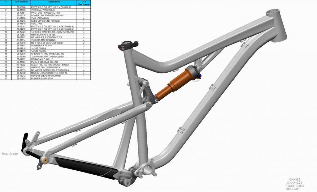
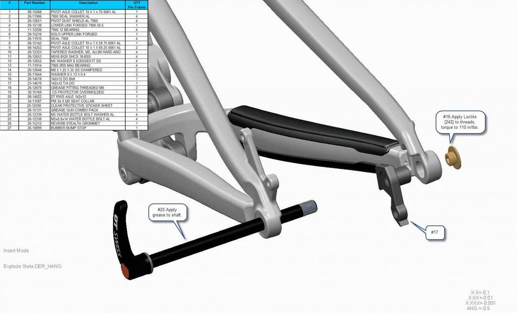
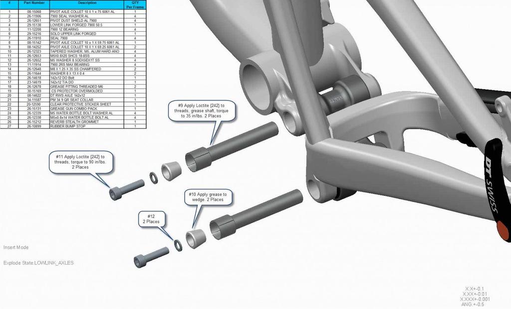
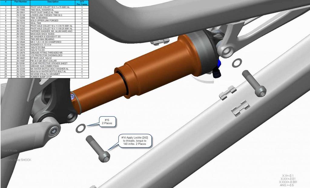
PIVOT SHUTTLE Owner's Manual
 PIVOT SHUTTLE Owner's Manual This manual is intended to provide you with the information needed to get you on the trail. This guide will walk you through the steps necessary to set up all the components
2005 RADIUM/ METEL SHOCK SERVICE MANUAL
 2005 RADIUM/ METEL SHOCK SERVICE MANUAL PN 042132,. '05 RADIUM/ METEL SHOCK SERVICE MANUAL Page 1 PN 042132 2005 RADIUM/ METEL SHOCK SERVICE MANUAL INDEX Section Description Page 1 INTRODUCTION 3 2 SETUP,
DUCATI MONSTER 696/796 CARTRIDGE KIT
 DUCATI MONSTER 696/796 CARTRIDGE KIT INSTALLATION OF THE KYB CARTRIDGE KIT Available for models Ducati Monster 696 and 796 from 2011 to 2014 This manual concerns the installation of the aftermarket KYB
TABLE OF CONTENTS. Introduction Shock Basics & Terminology General Maintenance... 5 XTC NRS AC/All Conditions Warp DS...
 Version 1.2 TABLE OF CONTENTS Introduction... 2 Shock Basics & Terminology... 3 General Maintenance... 5 XTC NRS... 6 AC/All Conditions... 8 Warp DS... 12 Protege/Cypress DS/MTX 250 DS... 15 Prodigy/Prodigy
Electrically Assisted Pedal Cycles. Assembly Instructions
 Electrically Assisted Pedal Cycles Assembly Instructions Version 4 23 Sept 2005 Introduction Thank you for buying a PowaCycle Freeway electric bike. We hope it brings you many hours of enjoyment. For safe
Z1 Free Ride INSTRUCTIONS GENERAL RULES
 INSTRUCTIONS GENERAL RULES 1. Where specified, assemble and disassemble the shock absorption system using the MARZOCCHI special tools only, as shown in the table below. 2. On reassembling the suspension
E.C.C. and AirTail Compressor Kit For the Airtail Suspension System Setup Instructions
 E.C.C. and AirTail Compressor Kit For the Airtail Suspension System Setup Instructions Note: Please read and follow the Installation Instructions first, then read and follow these Setup Instructions completely
Creation Date Last Mod Date Model Year Drawings Estimated Time. 5/22/2009 6/15/2009 S120/S90/E min.
 You are here: Service > Forks > 2008 > E100 > S120/S90/E100 50-hour Service Open the Specialized Business Online site in a new window... S120/S90/E100 50-hour Service Creation Date Last Mod Date Model
Owners Manual RUX ENGLISH
 Owners Manual RUX ENGLISH TABLE OF CONTENTS Overview 3 Tightening torques 3 Important safety information 4 Before every ride 5 Assembly instructions 6 20mm QR axle assembly 6 20mm bolted thru axle assembly
FLOAT 3 EVOL FACTORY SERIES OWNERS MANUAL
 FLOAT 3 EVOL FACTORY SERIES OWNERS MANUAL Contents CONGRATULATIONS... 3 CONSUMER SAFETY... 3 UNDERSTANDING THE FLOAT 3 EVOL... 4 FOX PUMP... 5 OPTIONS... 5 ADJUSTABLE PROGRESSIVE DUAL-STAGE AIR SPRING...
Shock manual V3.1 ENGLISH
 Shock manual V3.1 ENGLISH 2 Shock manual v3.1 INDEX Page Hyperpro Shock Overview 4 Maintenance 5 Rear Shock unit, removal and installation M1 Mono shock (& Telelever front) 6 M2 Twin shock 6 M3 Link system