ROUSSILLON MODEL Motor inside shaft 250 Nm
|
|
|
- Andrew Foster
- 6 years ago
- Views:
Transcription


1 ENGLISH AUTOMATIC POOL COVER INSTALLATION MANUAL ROUSSILLON MODEL Motor inside shaft 250 Nm ACCORDING TO NF P STANDARD TO READ CAREFULLY AND TO KEEP FOR LATER REFERENCE ZAC de Torremilla 105 Rue Henry Potez PERPIGNAN - FRANCE Tel: Fax: contact@eca-interpool.com 1/24 SERIAL Nº: Revision N : Revision number
2 TABLE OF CONTENTS - Personnel and material required for unloading and assembly. Page 02/24 - Components of the automatic pool cover. Page 03/24 - Warning. Page 04/24 - Bearing sides and motor assembly. Page 04/24 - Bearing sides with roller shaft assembly. Page 05/24 - Assembly in the pool. Page 06/24 - General installation in the pool. Page 07/24 - Fixing the plates in the wall level. Page 08/23 - Slat assembly. Page 09/24 - Slat direction. Page 10/24 - Slat with melted caps Assembly. Page 11/24 - Stair assembly. Page 12/24 - Partition assembly. Page 13/24 - Installation of beam s cases. Page 14/24 - Mounting of beam and counterweights. Page 15/24 - Electrical installation. Page 16/24 - Electrical connections. Page 17/24 - Limit switch adjustment Page 18, 19/24 - Connexion box isolation Page 20/24 - Safety Brackets & Straps Positioning. Page 21; 22; 23; 24/24 1/24 Revision number


 measuring tape")

3 ENGLISH UNLOADING OR TOOLS REQUIRED FOR ASSEMBLY Drill and drill bits for concrete Ø 6 and Ø10 Flat head screwdrivers Phillips screwdrivers Spirit level wrench Nippers Wire strippers 5 and 6 mm Allen wrench Hammer Standard and long (10 m) measuring tape Grease Metal saw UNLOADING TIME ASEMBLY TIME 0 h h 00 2/24 Revision number


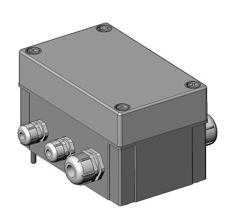
4 COMPONENTS OF THE AUTOMATIC POOL COVER One stand for motor side One stand for bearing side Connection box to fix on the stand Slat and strap assembly Roller shaft Aluminium beam with/ without partition for pit Electrical box Pit cover Counterweight Installation instructions Operation, care, winterising and maintenance instructions 3/24 Revision number


5 WARNING We recommend before performing any operation to read carefully the installation instructions and to check the following points: - Check the wall s hardness and particular those places where the bearing stands have to be placed. - To the installer, to carry out the best choice of the type of fixing and thus to avoid any wrenching of the supports (vertical push, direction low upwards, being able to reach 500 dan by support). - Make sure there is an efficient overflow drain; the overflow s shaft will be installed at 100 mm from the wall in order to avoid the submergence of the electrical box. Overflow drain tube is Ø40 mm mini) - It is recommendable an automatic water level. - Your automatic cover have been manufactured according to the manufacturing sheet, however we suggest checking, before doing any performance, that the slats can be properly placed in the pool. - Make sure that the power feeding is carried out from the right side of the pool. - The electrical installation must be done by a properly trained and qualified electrician. - The electrical box must be protected by a 30mA circuit breaker. (Not supplied by us). BEARING SIDES AND MOTOR ASSEMBLY MOTOR SIDE - Install on the deck in order to easily assembly the different components - Place the highest part of the angle bracket behind the vertical stand - Assembly the two parts with 4 stainless steel screws of diameter 8 and their washers - Tighten vigorously with a 13mm key BEARING SIDE - Proceed as follows: - Place the highest part of angle bracket behind the vertical stand - Assembly the two parts with the 4 M8 stainless steel screws and their washers. - Tighten vigorously with a 13mm key. Note: The assembly of bearing sides is not obligatory, the horizontal parts can be well positioned and fixed on the wall level to immediately fix the vertical parts on them. 4/24 Revision number


6 BEARING SIDES WITH ROLLER SHAFT ASSEMBLY FIXING OF SHAFT ON MOTOR BRACKET - Place the motor side of the roller shaft next to the motor bracket and put the power cable into the protection groove. - Attach the motor plate to the fixed part on the vertical side. - Grease the fixed shaft Ø 200mm, place it between the two parts immobilize it with the stainless steel pin. FIXING OF SHAFT ON BEARING SIDE - Place the bearing side of the roller shaft next to the bearing side. - Make sure there is a Ø8mm bolt at the end of bearing shaft and attach the black bearing with the bearing side, center this one and fix them with the two nuts. - Check that bearing shaft slides well through the tube of the roller shaft! Retaining ring Pin Ø 8mm 5/24 Revision number


7 ASSEMBLY IN THE POOL - Loose the fixing screw of the shaft bearing s fixing ring and introduce the set: shaft bearing bearing shaft towards the interior of roller shaft with a minimum dimension to make the assembly easier. Retaining ring - Proceed with the assembly of the system between two workers Pit covet Beam Overflow Drain Main drain 6/24 Revision number


8 GENERAL INSTALLATION IN THE POOL Liner fixing Pit cover Wall level Beam Water level Note: the motor pit can be placed on the right side or on the left side Skimmer Main drain Skimmer Right angle required at 90 A B A = B If solar slats are used, make sure there is a nozzle on the steps Note: The axis of the roller shaft and bearing should be perfectly parallel for a good assembly and at 90 to the pool length wall. ATTENTION: In presence of rays behind the roller, you will have: - To if required off-set the roller towards the basin by you ensuring that slats once rolled up on the roller shaft do not touch the liner in the rays - - You to ensure that the assembly of the beam and the pit cover is always realizable in spite of the new positioning of the roller 7/24 Revision number


9 FIXING OF PLATES After having placed the roller in the pool, it is important to put the bearings of the roller together against the walls of the pool. To do so, slide the bearing shaft and fix it by tightening the hexagonal M8 screw of the ring (see drawings) against the roller s tube. Fixing screw Retaining ring Slip bearing shaft After having decided the location and angle brackets of the pool, according to the installation system indicated on the previous page, it will be best to fix the plates through a Ø10mm drill, dowels and stainless steel screws included in the pack. Drill Ø 10mm depth 100mm Placing of brass dowels Ø10 mm and stainless steel countersunk-head screw M8 60 8/24 Revision number


10 SLAT ASSEMBLY * Immediately after taking the slats out of the packaging, they should be put into the water to prevent any possible deformation. *The number of slats has been determined according to the length of the pool, though there are 4 extra slats. * The first set of slats is easily recognisable as it has the straps to be fastening to the roller. Strap Roller shaft Fixation plate *Slide the strap under the fastening plates. *Centre the cover in the pool leaving enough space on both sides. *Tighten the attachment plates with a screwdriver * Bring closer the set of 7 slats to assemble them. 9/24 Revision number
.")


11 SLATS DIRECTION * Identify the upper side of the slats (curved side). * Identify the slats direction: - Wing to the stair - Groove to the roller shaft Stair Side Roller shaft Side Slat Side on the water SLATS ASSEMBLING Phase 1: Join the slats Phase 2: Join the wing to the groove Phase 3: Move both slats down Phase 4: Move them up and carry on with it until slats are perfectly engaged. 10/24 Revision number
 wing to groove.")


12 ASSEMBLING OF SLATS WITH MELTED CAPS: Phase 1: Place both slats (see above) wing to groove. Be careful with the slats direction. Phase 2: Slide the slats along. Stop it at the when the edges of of the slats are on line. Phase 3: slat Place the removable wing on to the and assemble the wing on to the cap Do the same for the following ones. 11/24 Revision number
 Assemble the slats until the stairs are completely assembled.")
 4 ) Centre the stair using this slat.")


13 STAIR SETTING ALLOWED DIMENSION X POOL COVER 1 ) Put the stair slats on the water 2 ) Assemble the slats until the stairs are completely assembled. 3 ) Centre the big width slats in the pool (allowed dimension X: from both sides of the pool) 4 ) Centre the stair using this slat. To assemble the stair slats to the pool slats, proceed as follows: Wing Notch Long width slat First stair slat Mark the position of both cap edges of the stair slat on the wing of the long width slat. Make two notches of a cap dimension on both sides of the stair on the wing of the long width slat without hurting the waterproof of the slat. 12/24 Revision number
 2) Partition")
 Wall Liner Seal")

14 PARTITION ASSEMBLY 1) Hanging partition model (attached below the coping stone) 2) Partition model for attachment to vertical walls Make sure the gasket is behind the liner) Wall Liner Seal (comes adhered to the support) M8 brass plug Screw M8 Seal Washer 13/24 Revision number
 With coping recoiling from 50mm/ vertical wall of the pool: The coping stones have been cut (in the case of")

15 INSTALLATION OF BEAM S CASES The installation of the beam s cases is rigorous. Two cases can come up: A) With coping recoiling from 50mm/ vertical wall of the pool: The coping stones have been cut (in the case of existing coping stone) or installed moving back from 50 mm (new pool) Coping stone Beam Vertical wall B) Without coping stone, with stainless steel frames angles to attach to the wall: Coping stone Poutrelle Mur vertical Angle inox Note: In the case of a model with partition, see also page 13/25 14/24 Revision number

.")
16 MOUNTING OF BEAM AND COUNTERWEIGHTS 1: Place the two beam support brackets on the embedding parts for the beam support, previously fixed, or directly on the wall, using screws. 2: Slide the counterweights along the beam slot and place Aluminium beam on support bracket. 3: Adjust the length of the counterweight when cover is completely unrolled over the pool surface. The counterweight should not touch the floor. 4: Place pit cover as indicated in the diagram (note: the beam section has been calculated to withstand pit cover only. Do not cover with concrete stabs). Tensioner coupling Pit cover Water level Beam Slat - type cover Shaft Ø 146mm Tensioner Counterweight 15/24 Revision number
 4 Circui breaker 30mA NOT INCUDED 1 Key switch cable: 3 1.5mm² Alimentation cable : 3 2.")
17 ELECTRICAL INSTALATION The electrical installation must be done in accordance with C15100 and P91C by a properly trained and qualified electrician. Protect the 220 Volts power for the box with a 30mA circuit breaker. (Not included ) 4 Circui breaker 30mA NOT INCUDED 1 Key switch cable: 3 1.5mm² Alimentation cable : mm² 3 Limit switch cable mm² 5 Power cable 2 6mm² to 15m 2 10mm² to 15m at 30m 2 1 : Key swith 2 : Shaft with motor ; 250Nm ; 24 Volts 3 : Connexion box to fix on the stand 4 : Electrical box (in the technical room) 5 : Electrical box switch 16/24 Revision number


18 ELECTRICAL CONNEXION Sector alimentation In case of an Electrolysis Electrolysis Cable Key switch Motor alimentation Limit switch adjustment captor Limit switch cable Connexion box to fix on the stand Key switch cable Motor cable Motor alimentation 17/24 Revision number


 Finished adjustment FOR INITIALIZE THE")

19 LIMIT SWITCH ADJUSTMENT ONLY AT THE 1st START First page at the time of the 1st start Support on The opening and the closing are accessible by the key switch INITIALIZING : 3 times and Motor on the RIGHT Motor on the LEFT - The cover being closed, to memorize while supporting on (Confirmation of the memorizing of closing = M) Roll the cover - The cover being opened, to memorize while supporting on (Confirmation of the memorizing of opening = M) Finished adjustment FOR INITIALIZE THE SYSTEM, SWITCH OFF THE BOX DURING 5 SECONDS AND TO START AGAIN IN THE PARAGRAPH INDICATED 18/24 Revision number
 can allow making it restart. «Err. Cycle»: The motor is fed ceaselessly during 5 minutes.")


20 ERRORS MESSAGES Errors messages : «Erreur Capteur»: The sign sensor count-turn does not change state. The system is stopped, only a new initialisation is possible (see 3rd) can allow making it restart. «Err. Cycle»: The motor is fed ceaselessly during 5 minutes. The manipulation is suspended and the motor is stopped during 20 seconds. Manipulation will not be able to be performed during this period. «Surintensité»: The circuit breaker is started if the intensity exceeded 10 A. the operation can be reiterated. On the same cycle of opening or closing, if this error occurs three times, this posting will flicker with the screen opposite. For initializing the system,you must be switch off the electrical box. 1. The screen points out permanently the number of turns counted or deducted by the automat. If the position of the motor was definitely pointed out and if linking are correct, the value of the meter is position closed (around 0) is less than the value of the meter in opened position (between 7000 and 8000). 2. One time delay postpones the bet under way the motor of one second when they speed up the key. This time delay allows stopping the shaft before leaving again in the other sense. 19/24 Revision number


.")

21 CONNEXION BOX ISOLATION The isolation of the connexion box must be done after installed and tested all the roller s connexion, and his functioning. White bottle Blue bottle Recipient Spatula For all the operations of isolation, the electrical circuit must be DISCONNECTED! 1/ Take off the electricity of the roller. 2/ In a recipient, to pour the two bottles (white and blue). 3/ To mix energetically with a spatula during 30 seconds, to obtaining an homogeny mixing. 4/ To pour this mixing, in the connexion box, to recovered the electrical connexion totally. 5/ Waiting 15 minutes, before take on the electrical circuit. 20/24 Revision number

")


22 BRACKET AND STRAP POSITION Warning: The position of the brackets is subject to the position of the skimmers in the pool. If these lasts bother the positioning of the safety Brackets, the positioning of the Brackets will be done taking into account the safety Brackets on the slats panels (If necessary move the straps) POSITION OF THE BRACKETS AND THE STRAPS Dimension Width less or equal to 3m = 2 straps Dimension Width from 3 to 5m = 3 straps Dimension Width from 5 to 7m = 4 straps Dimension Width superior to 7 m = 5 straps 50cm X X 50cm 50cm 1 strap at 50cm from the edge 1 strap in the middle of the stair 50 cm Fixed dimensions for all pools 1 strap centred if X <1m 1 strap at 50cm if X<2m 2 Straps if X>2m 2 straps on the stair at 50cm from the edge 21/24 Revision number

 Pin the supports.")


 Screw the")

23 SAFETY BRACKETS POSITIONING: ABS BRACKETS: 1) When positioning the brackets make sure the shaft of the brackets is placed at 500 mm from the edge of the pool. 2) Pin the supports. Put the strap between the fixation plate and the bracket and keep the strap tense. 3) Tighten the screws until complete closing of the brackets. Bracket Inox to be fixed to the wall + screws: 1) When positioning the safety brackets 2) Screw the supports. the shaft of the brackets must be return type Put the return safety strap. placed at 500 mm from the edge of the pool. 3) Clip both sides together. 22/24 Revision number
 When positioning the safety brackets, 2) Put the pin")


 Clip both sides together.")
 Make two Ø10")

24 Inox Bracket for model under construction + screws: 1 2 1) When positioning the safety brackets, 2) Put the pin M8 in the Ø10 wholes. The shaft of the brackets must be put at Screw until complete closing of the brackets. 500 mm from the edge of the pool. Put the return safety strap in the brackets. 3 3) Clip both sides together. Inox Brackets for renovation model + screws: 1) Cut the coping stone with a angle grinder 2) Make two Ø10 wholes. Place the M8 pin in the wholes. Screw until complete closing of the safety brackets. Put the straps through as per drawings 2 and 3. 3) Replace the coping stone cut with an adequate product. 23/24 Revision number


 Tighten the screws until complete closing of the brackets.")
25 ABS brackets INOX support: 1) When placing the safety brackets, The shaft of the brackets must be placed at 500 mm from the edge of the pool. 500mm 2) Screw the supports. Put the strap through the fixation plate and the strap. Clip both sides of the strap and keep it tense. 3) Tighten the screws until complete closing of the brackets. 24/24 Revision number

26 25/24 Revision number
27 26/24 Revision number
ABOVE-GROUND AUTOMATIC POOL COVERS
 ABOVE-GROUND AUTOMATIC POOL COVERS VALLESPIR MODEL INSTALLATION AND MAINTENANCE MANUAL SERIAL N : Revision number: 003-2008-01-01 TABLE OF CONTENTS - Personnel and material required for unloading and assembly
ABOVE-GROUND AUTOMATIC POOL COVER
 ABOVE-GROUND AUTOMATIC POOL COVER CAPCIR MODEL INSTALLATION AND MAINTENANCE MANUAL Serial N : Revision number: 004-2008-01-01 TABLE OF CONTENTS - Personnel and material required for unloading and assembly
AUTOMATIC POOL COVER. Serial number: ENGLISH N'CARLIT MODEL INSTALLATION MANUAL AND MAINTENANCE /18 Revision number
 AUTOMATIC POOL COVER N'CARLIT MODEL INSTALLATION MANUAL AND MAINTENANCE Serial number: Revision number: 002-2012-10-05 - 1 -/18 Revision number 002-2012-10-05 TABLE OF CONTENTS UNLOADING... 2 TOOLS REQUIRED
AUTOMATIC POOL COVER. Serial number: ENGLISH SOLAR CARLIT MODEL INSTALLATION MANUAL AND MAINTENANCE /18 Revision number
 AUTOMATIC POOL COVER SOLAR CARLIT MODEL INSTALLATION MANUAL AND MAINTENANCE Serial number: Revision number: 008-2008-01-31 - 1 -/18 Revision number 008-2008-01-31 TABLE OF CONTENTS - Personnel and material
MH2 For automatic security cover decks of pools
 MH2 For automatic security cover decks of pools DIFFUSION Name Commercial dpt SIREM Customers Gestion des évolutions Index Evolution desciption 00 Document creation 01 02 03 04 05 06 Department / Function
A B C D E F. Tools Required (supplied by others)
") Page 1 of 17 Parts List Below Deck Automatic Retractable Security Cover Kit (1) Tube End Bearing Plate (A) (1) Rope Reel and Cover Drum Motor Assembly (B) (1) Cover Drum (1) Pulley Support Channel (2)
Page 1 of 17 Parts List Below Deck Automatic Retractable Security Cover Kit (1) Tube End Bearing Plate (A) (1) Rope Reel and Cover Drum Motor Assembly (B) (1) Cover Drum (1) Pulley Support Channel (2)
Installation Guide Current Ford F-250 & Ford F-350 Super Duty. Product Code: 109 & 119
 Installation Guide 2008 - Current Ford F-250 & Ford F-350 Super Duty Product Code: 109 & 119 September 1, 2012 Tools Needed Components Included 3/8" Drill P2 Tip #2 Philips Screwdriver 1/2" Drill Bit Hinged
A B C D E F. b.tools Required (supplied by others) 3/16" Drill Bit 3/8" Wrench Phillips Head Screwdriver
 3/16 Drill Bit 3/8 Wrench Phillips Head Screwdriver") Page 1 of 13 5E.1 Parts List a. Below Deck Automatic Retractable Security Cover Kit (1) Tube End Bearing Plate (A) (1) Rope Reel with Motor Attached (B) (1) Rope Reel Cover (C) (1) Cover Drum (1) Cover
Page 1 of 13 5E.1 Parts List a. Below Deck Automatic Retractable Security Cover Kit (1) Tube End Bearing Plate (A) (1) Rope Reel with Motor Attached (B) (1) Rope Reel Cover (C) (1) Cover Drum (1) Cover
Rollstar Shade Installation Instructions
 Rollstar Shade Installation Instructions All Lifting Systems Inside or Outside Mount Thank you for purchasing your new Rollstar shade. It has been custom-made from the highest quality materials to the
BROOKS STAIRLIFTS SUPERGLIDE 120
 BROOKS STAIRLIFTS SUPERGLIDE 120 INSTALLATION PROCEDURES CONTENTS Health And Safety Hazards 3 Unpacking the Stairlift Carriage 4 Pre-Installation Procedure 5 Box Contents 6 Installation Tools 9 1.1 Required
AP-Xtreme Sim-Racing Chassis Master Assembly Guide
 AP-Xtreme Sim-Racing Chassis Master Assembly Guide This guide covers all options available for the AP-Xtreme chassis. Some sections of this guide will be skipped based on the options chosen. APX1000 APX2000
Installation Guide Rollerdor RD55 Econ Roller Garage Door
 Installation Guide Rollerdor RD55 Econ Roller Garage Door 1 Finished door Rollerdor RD55 Econ Roller Garage Door CHECKLIST & COMPONENTS EQUIPMENT REQUIRED 2 x Step ladders or hop ups Spirit level Tape
INSTALLATION MANUAL. Melink Corporation (513) Revision
 Revision") INSTALLATION MANUAL Revision 130711 Table of Contents Step Installation Contractor Page 1 Install System Controller Electrical 4 2 Install Variable Frequency Drive Electrical 6 3 Install Touchpad Mechanical
INSTALLATION MANUAL Revision 130711 Table of Contents Step Installation Contractor Page 1 Install System Controller Electrical 4 2 Install Variable Frequency Drive Electrical 6 3 Install Touchpad Mechanical
Technical Installation Manual
 Lighting Step and Aisle Safety Lighting Technical Installation Manual 1 Contents Page 3 Tools required 4 Installation detail & planning 5 Adhesives, silicone & crimps 6 General cinema layout 7 Basic wiring
Operator's manual. TruTool F 140 (1A1) english
 english") Operator's manual TruTool F 140 (1A1) english Table of contents 1. Safety...3 2. Description...5 2.1 Intended use...6 2.2 Technical data of the TruTool F 140...7 2.3 Lock seams...8 3. Tool assembly...10
Operator's manual TruTool F 140 (1A1) english Table of contents 1. Safety...3 2. Description...5 2.1 Intended use...6 2.2 Technical data of the TruTool F 140...7 2.3 Lock seams...8 3. Tool assembly...10
USER MANUAL SUMMARY. Tipping Device p 2. Remote Control p 4. Motorised Rollers p 6. Ramp and Board p 8. Charge and Battery p 10
 USER MANUAL SUMMARY Tipping Device p 2 Remote Control p 4 Motorised Rollers p 6 Ramp and Board p 8 Charge and Battery p 10 Electric Circuit Diagram p 12 KLAVIER-ROLLER 353 rue des Marais F- 74410 SAINT-JORIOZ
X-JET (Counter current system)
") X-JET (Counter current system) GB Instruction Manual Translation of the original 27131 - A SOMMAIRE Contents 1 General... 3 1.1 Warranty instructions... 3 1.2 General... 3 1.3 Usage instructions... 3 2
X-JET (Counter current system) GB Instruction Manual Translation of the original 27131 - A SOMMAIRE Contents 1 General... 3 1.1 Warranty instructions... 3 1.2 General... 3 1.3 Usage instructions... 3 2
PURESTREAM SYSTEM - ASSEMBLY GUIDE
 PURESTREAM SYSTEM - ASSEMBLY GUIDE INSTRUCTION VIDEO LINK: www.cagpurification.com/installment--procedure--videos.aspx OR SCAN CODE BELOW pipes fittings for compressed air NECESSARY TOOLS FOR INSTALLATION
CompassPools Rollo Cover. Installation Manual
 CompassPools Rollo Cover Installation Manual Contents I. II. III. IV. V. VI. VII. VIII. IX. General Installation Instructions Installation of the Mechanism Installation of the panel Installation of the
Installation Guide Classic Silverado / Sierra PRODUCT CODES: 206 & 216
 Installation Guide 1999-2007 Classic Silverado / Sierra PRODUCT CODES: 206 & 216 Tools Needed: 3/8" Drill 1/2" Drill Bit Installation Guide Components Included: Lid #2 Phillips Screwdriver Track(s) x2
2014+ FORD FIESTA ST DIRECT-FIT OIL COOLER KIT PARTS LIST AND INSTALLATION GUIDE CAUTION PARTS INCLUDED NOTE TOOLS NEEDED INSTALL PROCEDURE
 PARTS LIST AND PARTS INCLUDED 3PC APPLICATION-SPECIFIC MOUNTING BRACKETS & SPACER 1PC 19-ROW OIL COOLER 1PC 4 ', X 1'' BRAIDED HOSE W/90-10AN FITTINGS 1PC 3'' X 2.5 '' BRAIDED HOSE W/45 AND 90-10AN FITTINGS
Fitting Instructions
 Reverse Park Assist Suitable for: Isuzu MU-X Kit Part No: / 5466XX D-Max Tow-Pro Wiring Kit Fitting Instructions Suitable for: Isuzu MU-X / D-Max Accessory Kit Estimated Fitting Time: 0 Minutes FI967 Page
INSTALLATION GUIDE STANDARD PRODUCT CODES:
 INSTALLATION GUIDE STANDARD PRODUCT CODES: 100, 105, 110, 111, 112, 113, 115, 120, 130, 140, 145, 146, 150, 200, 210, 240, 250, 255, 260, 300, 305, 405, 406, 407, 408, 425, 426, 435, 447, 500, 505, 510,
Heavy duty slurry pumps
 USERS MANUAL Heavy duty slurry pumps TOYO PUMPS EUROPE Edition 27.07.2007 SAFETY INSTRUCTIONS TOYO PUMPS EUROPE Users manual for Toyo pumps type «DP..-6 30~40HP» This users manual will help you to maintain
Installation Manual. For. Trident Boat Lifts
 Installation Manual For Trident Boat Lifts Page 2 Safety Precautions 1. Your boat lift is a heavy duty piece of equipment. It is important that all persons that may operate this unit have read and understood
Wood Grain Warrior Line Incognito hidden winch bumper installation instructions Lexus GX470
 Wood Grain Warrior Line Incognito hidden winch bumper installation instructions 2003-2009 Lexus GX470 Version 1.0-2016 Thank you for purchasing the Southern Style OffRoad Wood Grain Warrior Line Lexus
MULTILUBE SYSTEM INSTALLATION AND MAINTENANCE
 MULTILUBE SYSTEM TABLE OF CONTENTS 1 PUMPING UNIT INSTALLATION...1 1.1 Installing the supporting blocks and the pumping unit...1 1.2 Installing the main line on the pumping unit...3 1.3 Installing the
EL Beam Sensors Standard & SC Versions
 EL Beam Sensors Standard & SC Versions 56801399 Copyright 2008 Slope Indicator Company. All Rights Reserved. This equipment should be installed, maintained, and operated by technically qualified personnel.
IE Audi 3.0T Crank Pulley Upgrade Install Guide IEBAVJ3
 IE Audi 3.0T Crank Pulley Upgrade Install Guide IEBAVJ3 Thank you for purchasing your IE 3.0T crankshaft pulley upgrade! This instruction guide is used for installation of IE s lower overdrive pulley for
Removing/installing final drive
 1(16) Removing/installing final drive Special tools: 998 5972, 999 5561, 999 5652, 999 5659, 999 5660 Removing Note! Position the rear lifting arms on the arrows on the sills. This is so the support arm
Speedometer log sensor
 Speedometer log sensor Paddlewheel Product reference : 90-60-457 USER GUIDE and INSTALLATION GUIDE nke Sailing competition Z.I. Kerandré Rue Gutenberg 56700 HENNEBONT- FRANCE http://www.nke.fr n indigo
INSTALLATION INSTRUCTIONS SERVICE MANUAL
 INSTALLATION INSTRUCTIONS SERVICE MANUAL This manual provides instructions for the proper installation of the L 06 HAWLE stair lift. It is necessary to read and understand the contents of these instructions
Fuel pump unit, changing
 1(11) Fuel pump unit, changing Special tools: 981 2270, 981 2273, 981 2282, 998 5972, 999 5484, 999 5485, 999 5561, 999 5666, 999 5673 Safety See first Safety regulations for handling fuel. Preparation
REEDSTER 125cc. versions: F1 - F2 - F3 - F4 OVERHAULING MANUAL
 REEDSTER 125cc versions: F1 - F2 - F3 - F4 OVERHAULING MANUAL 07/11/07 21/01/2009 1 INDEX Page 1. - REEDSTER 125cc ENGINE DISASSEMBLY 1 2. - CRANKSHAFT DISASSEMBLY / ASSEMBLY 13 2.1 - CRANKSHAFT DISASSEMBLY
Injector Extraction Kit for the M9R / M9T
 Work Instructions Injector Extraction Kit for the M9R / M9T 60385095 Tensile Force Limiter 60385229 page 1 of 40 page 2 of 40 Safety notice Important! Be sure to read these instructions before assembling,
JEEVES. JEEVES Installation Manual. Installation Manual The Easiest Do-It-Yourself Dumbwaiter on the Market
 1 888-323-8755 www.nwlifts.com JEEVES Installation Manual The Easiest Do-It-Yourself Dumbwaiter on the Market This manual will cover the installation procedure step-by-step. The installation of this dumbwaiter
CHECKLIST & COMPONENTS
 Eclipse Compact www.rollershuttercompany.com Tel 0800 6444121 55mm Roller Garage Doors CHECKLIST & COMPONENTS EQUIPMENT REQUIRED 2 x Step ladders or hop ups Spirit level Tape measure Power drill 10mm A/F
Installation Instructions
 Installation Instructions Speedcook Oven Read carefully. Keep these Instructions. INSTALLATION INSTRUCTIONS Electrical Requirements Product rating is 240/208 volts AC, 60 Hertz, 30 amps and 6.5 kilowatts.
Trackstar Motorized Folding Shade Installation Instructions
 Trackstar Motorized Folding Shade Installation Instructions Thank you for purchasing your new Trackstar folding shade. It has been custom-made from the highest quality materials to the dimensions you specified.
Installation Instructions Studio Makeup Station
 Installation Instructions Studio Makeup Station 30" and 36" Models 5-light 30" Studio Makeup Station 8-light 30" Studio Makeup Station 6-light 36" Studio Makeup Station 9-light 36" Studio Makeup Station
Installation Instructions Capacity 10,000 lbs. (100 Series Lift)
") Installation Instructions Capacity 10,000 lbs. (100 Series Lift) IMPORTANT Reference ANSI/ALI ALIS, Safety Requirements for Installation and Service of Automotive Lifts before installing lift. OPERATING
Installation Instructions Capacity 10,000 lbs. (100 Series Lift) IMPORTANT Reference ANSI/ALI ALIS, Safety Requirements for Installation and Service of Automotive Lifts before installing lift. OPERATING
INSTALLATION GUIDE DODGE PRODUCT CODE:
 INSTALLATION GUIDE 2002-09 DODGE 1500-3500 PRODUCT CODE: 445 & 455 May 17, 2011 TOOLS NEEDED COMPONENTS INCLUDED 3/8" Drill P2 Tip 1/2" Drill Bit #2 Philips Screwdriver Flange(s) x 2 Hinged Lid Track(s)
LK Shunt Cabinet VS2, Shunt Cabinet VS2 Prefab
 LK Shunt Cabinet VS2, Shunt Cabinet VS2 Prefab Design LK Shunt Cabinet VS2 The LK Shunt Cabinet VS2 is designed to be used when you wish to hide the LK Manifold RF and LK Manifold Shunt VS2. The cabinet
Pull out clutch E snap ring and withdraw complete clutch pack of clutch E. 6 HP 26 ZF Getriebe GmbH Saarbrücken CD
 Press down cup spring in the mandrel press with assembly bracket 5x46 002 566 and remove snap ring with suitable pliers. Take out planet carrier and cup spring. Take the O-ring seal off the planet carrier.
Signature Overhead System INSTALLATION MANUAL
 Signature Overhead System TM INSTALLATION MANUAL PACLINE Installation Manual Read All Instructions Carefully Proper installation is not difficult, and by adhering to the following procedures the conveyor
AU DU PONT DE LUTTRE BRUSSELS BELGIUM PHONE: FAX: OPERATING MANUAL. Electric Fully Automatic Floor Saw FS 1218 EX
 AU DU PONT DE LUTTRE 74-1190 BRUSSELS BELGIUM PHONE: 322 34 83 162 FAX: 322 34 83 136 OPERATING MANUAL Electric Fully Automatic Floor Saw FS 1218 EX 2 Important information before you start! When the machine
FOLDING DOOR ASSEMBLY AND MAINTENANCE MANUAL
 FOLDING DOOR ASSEMBLY AND MAINTENANCE MANUAL *ACMAP1* ACMAP1 INS-TEC-GC-40.02 V1 Rev.: 11.2005 INDEX PACKAGING CONTENT...3 TECHNICAL DRAWING...3 OPERATOR ASSEMBLY INTO THE CABIN DOOR...4 SILL ASSEMBLY...4
Mirror Solutions Bevel & Pivot Models Installation Instructions INSTALLATION INSTRUCTIONS. Figure 1
 Installation Instructions Mirror Solutions Bevel & Pivot Models 620095-620098 Mirror Solutions Bevel - Models # 620095 & 620096 Mirror Solutions Pivot - Models # 620097 & 620098 Figure 1 INSTALLATION INSTRUCTIONS
Property of American Airlines
 Date Maintenance Check list The inspection and preventive maintenance schedule of the Power Stow Rollertrack is as follows: Daily (10 hrs), Weekly (50 hrs.), every 6 months ( hrs.), yearly (1 hrs.) and
CENTER BELT SYSTEM INSTALLATION INSTRUCTIONS CARCG121220
 CENTER BELT SYSTEM INSTALLATION INSTRUCTIONS 2013+ DODGE CHARGER Distributed by CARCG121220 Important Notice: Read all instructions before starting the installation of the seat. Before drilling or installing
Sliding Door Fittings, Roller Shutters Vertical Sliding Door Fittings
 Vertico 16 VF, door weight up to 15 kg, for 2 bi-parting doors Door height: 300 600 mm Door thickness: Min. 16 mm Side panel thickness: Min. 1 mm Running gear: Top and bottom running, 4 rollers, with ball
Top Down Rollstar Shade Installation Instructions
 Top Down Rollstar Shade Installation Instructions Thank you for purchasing your new Rollstar shade. It has been custom-made from the highest quality materials to the dimensions you specified. With proper
Midi Traffic Light installation manual TRAFFIC CONTROL ACCESSORIES
 Midi Traffic Light installation manual TRAFFIC CONTROL ACCESSORIES Company Profile 1986 1990 1995 1999 Centurion Systems today In-house R & D development team Manufacture to international quality standard
Installation instructions, accessories - Electric engine block heater
 S60 / V70 (00-08) / S80 (-06) / V70 XC (01-) / XC70 (-07) / XC90 Section Group Weight Year Month (Kg/Pounds) 8 876 2/4.4 2006 09 S60 2001 D5244T, S60 2002 D5244T, S60 2002 D5244T2, S60 2003 D5244T, S60
Property of American Airlines
 Date Maintenance Check list This document describes the inspection and maintenance of the Power Stow Rollertrack. Maintenance refers to a time span. The operation hours are shown on the Power Stow Display
Page 1 of 17. Part# M0200 Rev.11 7/29/2016
 Part# M0200 Rev.11 7/29/2016 This manual contains important information concerning the installation and operation of the product listed above. Read manual thoroughly and keep for future reference INSTRUCTIONS
Crestline Dampening System. Installation Instructions. Hamada RS34 & VS34 Satellite Unit. For Presses Originally Equipped With. Integrated Dampeners
 Crestline Dampening System Installation Instructions Hamada RS34 & VS34 Satellite Unit For Presses Originally Equipped With Integrated Dampeners X88-113 01/2001 Rev-A GENERAL INFORMATION ATTENTION CRESTLINE
CVR-625. Compact Vibrating Rod Instruction Manual
 CVR-625 Compact Vibrating Rod Instruction Manual BinMaster: Division of Garner Industries 7201 N. 98th St., Lincoln, NE 68507 402-434-9102 email: info@binmaster.com www.binmaster.com OPERATING INSTRUCTIONS
Siemens Industrial SITRANS F US SONOFLO. Ultrasonic flowmeter Type SONOKIT hot-tap mounted. Manual, amendment *085R9429*
 s Manual, amendment SITRANS F US SONOFLO Ultrasonic flowmeter Type SONOKIT hot-tap mounted 1- and 2-track DN 200 - DN 4000 Amendment to product manuals for SONOKIT 1- and 2-tracks [ ] Order no.: FDK:521H1050
INSTALLATION INSTRUCTIONS SUPERPLANE 2.5. Suspended. A nd Avenue, Unit 1 Oakland, CA P E W alwusa.
 INSTALLATION INSTRUCTIONS SUPERPLANE 2.5 Suspended A 1035 22nd Avenue, Unit 1 Oakland, CA 94606 P 510.489.2530 E TalkToUs@alwusa.com W alwusa.com SP2.5S - Safety & Warnings! 1. Read all instructions. 2.
s_enn Exterior Stainless Steel Shading System by Draper
 Installation Instructions s_enn Exterior Stainless Steel Shading System by Draper Caution 1 Never push the bottom rail of the system up by hand. This can cause irreparable damage. Access equipment must
Standard program. Tool cases. ...convincing solutions. Hard top tool cases, Leather tool cases
 Standard program Tool cases Hard top tool cases, Leather tool cases...convincing solutions Assortment boxes, wallets, tool cases Metal tool boxes 5 compartments, complete black powder coating Tool case
CAUTION: Never work on a hot exhaust system. Allow time for the vehicle to cool. Always wear eye protection when working under a vehicle.
 Please take time to read and understand these installation instructions. CORSA Exhaust System Installation We recommend that the installation of this system be performed by a qualified service center or
Rear axle, servicing (frontwheel-drive
 Page 1 of 26 42-1 Rear axle, servicing (frontwheel-drive vehicles) WARNING! Do not attempt to weld and/or straighten the axle beam. Do not re-use fasteners that are worn or deformed in normal use. Some
Fitting Instructions
 Reverse Park Assist Suitable for: Nissan Navara Kit Part No: 5466XX NP00 Tow-Pro Wiring Kit Fitting Instructions Accessory Kit Estimated Fitting Time: 0 Minutes FI98 Page 0 of 5 General Notes Read through
Fabric Studio Custom Roll Shades Installation Instructions
 Fabric Studio Custom Roll Shades Installation Instructions Cassette System Battery Motor Lifting System Inside or Outside Mount Thank you for purchasing your new roll shade. It has been custom-made from
Roller Shades CORD LOOP. Head Rail, Fascia and No Head Rail. Installation & Care Instructions
 Roller Shades CORD LOOP Head Rail, Fascia and No Head Rail Installation & Care Instructions 152038 H 5/30/2017 GETTING STARTED A few simple tools are required: - Measuring tape - Power drill, drill bits
Vacuum Circuit-Breakers, Type HVX kv, of cassette design, cassette with motor drive
 Vacuum Circuit-Breakers, Type HVX 12 24 kv, of cassette design, cassette with motor drive Operating Instructions No. 531 321, Edition 09/00 Table of Contents 1 General 4 1.1 Operating Conditions 4 2 Design,
NSGV EVE-ER I, O, & M MANUAL
 TABLE OF CONTENTS Rail Layout.. Page 1 Support Placement...Page 1 Rail Assembly.Page 1 Rail Duct Connections.. Page 2 Rubber Lip Installation.. Page 3 Pneumatic End Stop. Page 4 End Stop. Page 4 End Cap..
Development of Relief Valve Automatic assembly technology
 Development of Relief Valve Automatic assembly technology Technology Explanation Development of Relief Valve Automatic assembly technology TAKIGUCHI Masaki Abstract Construction machinery is equipped with
EVAC Commercial Marine Equipment TOILET TECHNICAL DATA EVAC 90, STAINLESS STEEL, FLOOR MODEL, *SHOCK TESTED. Fresh water.
 16 Apr 2009 Doc. 1:141J TECHNICAL DATA 5327002 EVAC 90, STAINLESS STEEL, FLOOR MODEL, *SHOCK TESTED Fresh water connection Shut-off valve Strainer Vacuum breaker 390 Gasket Seat and cover Pneumatic push
GPS AutoSteer System Installation Manual
 GPS AutoSteer System Installation Manual Supported Vehicles New Holland Combines CR 9040 CX 9040 CR 9050 CX 9050 CR 9060 CX 9060 CR 9070 CX 9070 CR 9080 CX 9080 IntelliSteer Ready PN: 602-0231-01-A LEGAL
Insta-Valve 250 Patriot TM
 Insta-Valve 250 Patriot TM 4-12 Nominal Size Installation Instructions for use with the Hydra-Core Pipewall Sampling Kit IV250MAN 4-12 IV 250 PWSK v1.93 Revised 07/11/2018 Covered by United States Patent
Deuce/Ace Installation Instructions
 HARDWARE KIT: Upper Mounting Plate: 2-7/16" (11mm) X 3.5" bolts 2-7/16" flange nuts 2-2" spacers 2-7/16" trim cap mounting washers 2 - plastic trim caps TOOLS NEEDED: safety glasses wrenches 16mm or 5/8"
Installation instructions, accessories. Electric engine block heater, 230V, 5 cyl diesel
 Installation instructions, accessories Instruction No 30795311 Version 1.2 Part. No. 31373138 Electric engine block heater, 230V, 5 cyl diesel IMG-256423 Volvo Car Corporation Electric engine block heater,
Training Documentation
 Training Documentation Manual Shades There are two styles of adjustment wheels for Manual Shades: External Adjuster No tools needed. Wheel is turned by hand. Slot Adjuster (Accessed thru bracket end) Flat
Engine Dismantle and Assemble ( )
") Engine Dismantle and Assemble (2 34 8) Special Tools 2-036A Remover for pilot bearing 2-37 Oil seal installer/aligner 237 2036A 2-044A Installer/Aligner, Pilot Bearing/Clutch Plate 244 2-44 Inlet manifold
Engine Dismantle and Assemble (2 34 8) Special Tools 2-036A Remover for pilot bearing 2-37 Oil seal installer/aligner 237 2036A 2-044A Installer/Aligner, Pilot Bearing/Clutch Plate 244 2-44 Inlet manifold
MC2 BOWLING Pin-Setter
 MC2 BOWLING Pin-Setter File No.: M200509-01 COPYRIGHT 2005, VIA BOWLING PRODUCTS Content I. Installation of Front-End Assembly --------------------------------------- 1 II. Installation of Back-End Assembly
Removable Applied Panel Mounting System
 Removable Applied Panel Mounting System Every attempt has been made to ensure that this documentation is as accurate and up-to-date as possible. However, Vertical Express assumes no liability for consequences,
ARB WINCH/NON WINCH BUMPER TO SUIT MITSUBISHI PAJERO NM FLARED. EXCLUDING EXCEED MODEL WARNING
 ARB WINCH/NON WINCH BUMPER TO SUIT MITSUBISHI PAJERO NM FLARED. EXCLUDING EXCEED MODEL PRODUCT No. 3934020 Sahara Bar 3034020 Sahara Bumper FITTING KIT No. 6171383, 6171762, 6171363 WARNING FOR VEHICLES
SUBMERSIBLE DIRTY WATER PUMP
 FOR USE WITH A 110V SUPPLY ONLY SUBMERSIBLE DIRTY WATER PUMP MODEL NO: DWP210A PART NO: 7230102 OPERATION & MAINTENANCE INSTRUCTIONS LS0115 INTRODUCTION Thank you for purchasing this CLARKE Submersible
ZIPSCREEN EXTREME INSTALLATION MANUAL. February 2017
 ZIPSCREEN EXTREME INSTALLATION MANUAL February 2017 CONTENTS February 2017 This manual is to be read in conjunction with the Product Specifications & Assembly manual SECTION NO. DESCRIPTION PAGE NO. SECTION
Cellular Shades MOTORIZED SHADE Top Down - Bottom Up. Installation & Care Instructions
 Cellular Shades MOTORIZED SHADE Top Down - Bottom Up ucontact@udoblinds.com 1-855-205-8442 Installation & Care Instructions 152746A 7/2/2018 GETTING STARTED A few simple tools are required: - Measuring
1. Get fork mounted in stand. You can leave it in the bike, but you must remove the wheel and front brake.
 Tools Needed: Bike stand Lint free shop Towels 1.5mm Allen Key Pick Set Grease (We recommend Slick Honey) Oil Measuring Cup (with cc Scale) Small Metal Drift Shop Vise Oil Bucket 13mm Deep Socket (6 point)
3PC TONNEAU COVER WITH SPORTS BAR INSTALLATION INSTRUCTIONS
 3PC TONNEAU COVER WITH SPORTS BAR INSTALLATION INSTRUCTIONS TC00d / Vehicle Description: NISSAN NAVARA D0 DUAL CAB 3-PIECE TONNEAU COVER PARTS LIST NO. PART NAME QTY. NO. PART NAME QTY. NO. PART NAME QTY.
BOTTOM END SERVICE TOOLS SERVICE PRODUCTS ENGINE, CVT AND GEARBOX Subsection 10 (BOTTOM END)
") BOTTOM END SERVICE TOOLS Description Part Number Page CRANKCASE SUPPORT MAG/PTO... 529 036 031... 151 CRANKSHAFT LOCKING BOLT... 529 035 617... 154 DRIVE SHAFT OIL SEAL INSTALLER... 529 036 028... 143
BOTTOM END SERVICE TOOLS Description Part Number Page CRANKCASE SUPPORT MAG/PTO... 529 036 031... 151 CRANKSHAFT LOCKING BOLT... 529 035 617... 154 DRIVE SHAFT OIL SEAL INSTALLER... 529 036 028... 143
TR-254 Passive Skimmer and optional TR inch Extension Canister Assembly and Installation Instructions.
 TR-254 Passive Skimmer and optional TR-255 4 inch Extension Canister Assembly and Installation Instructions. Copyright 2007 DGSI. All Rights Reserved. This equipment should be installed, maintained, and
DrVanos.com Stage II Installation Instructions. Tool rental is available with the purchase of a vanos kit *See website for more info*
 DrVanos.com Stage II Installation Instructions Special Tools Needed: Camshaft locking tool TDC Crank pin Sprocket turning tool Tool rental is available with the purchase of a vanos kit *See website for
B5 A4 1.8t Front Mount Intercooler Install Instructions
 B5 A4 1.8t Front Mount Intercooler Install Instructions Only work underneath your vehicle after properly supporting it with adequate jack stands on a flat surface. NEVER work under a vehicle only supported
SUNROOF - SERVICE INFORMATION ADJUSTMENTS
 SUNROOF - SERVICE INFORMATION DESCRIPTION OPERATION DIAGNOSIS AND TESTING POWER TOP - SUNROOF SUNROOF ASSEMBLY-MODULE REMOVAL INSTALLATION CHANNEL-DRAIN REMOVAL INSTALLATION COVER-GUIDE MECHANISM REMOVAL
1PC TONNEAU COVER INSTALLATION INSTRUCTIONS IMPORTANT
 For use in cleaning painted metal, glass and other vehicle surfaces. For external use only. Dispose of properly after use. IMPREGNATED WITH 70% ISOPROPLY ALCOHOL TC0d PC TONNEAU COVER INSTALLATION INSTRUCTIONS
TABLE OF CONTENTS. Cordless Hammer Drill & Driver. Model No. EY79A2. Europe Oceania
 ORDER NO. PTD1511X06CE Cordless Hammer Drill & Driver Model No. EY79A2 Europe Oceania TABLE OF CONTENTS PAGE 1Warning--------------------------------------------------------------2 2Specifications-----------------------------------------------------2
INSTALLATION, MAINTENANCE, & SAFETY INSTRUCTIONS
 Tarpaulin Systems Flip -N- Go / Quick Mount Flip -N- Go System INSTALLATION, MAINTENANCE, & SAFETY INSTRUCTIONS (800) CRAMARO (800) 272-6276 Plants In: Delaware, Florida, Massachusetts, Nevada, Ohio Install
Installation Guide Rollerdor RD77 Econ Roller Garage Door
 Installation Guide Rollerdor RD77 Econ Roller Garage Door 1 Finished door Rollerdor RD77 Econ Roller Garage Door CHECKLIST & COMPONENTS EQUIPMENT REQUIRED 2 x Step ladders or hop ups Spirit level Tape
Installation Instructions
 Installation Instructions Product: SwitchBlade Swaybar System Part Number: PN 9100 Application: Jeep Wrangler TJ, 1997-06 (front) Welcome CONGRATULATIONS on purchasing a SwitchBlade Swaybar System from
VECTRIX VX-2 SERVICE MANUAL. Version 1.0/May 2011 VECTRIX, LLC
 www.vectrix.com CONTENTS SECTION A: Tools 1 Tools Needed SECTION B: Mechanical Parts 1 Front Fairing 2 Front Console Cover 3 Speedometer Cover 4 Front Vertical Panel Cover-Lower 5 Front Vertical Panel
Replacing the fuel tank
 Page 1 of 11 Replacing the fuel tank Special tools: 999 5720 Preparation Note! On cars up to chassis number 104221 the fuel filler pipe must be replaced when the fuel tank is replaced. Drain the fuel from
1. GENERAL SAFETY INSTRUCTIONS 2. GENERAL SAFETY RULES GENERAL OBSERVATIONS.
 ENGLISH IMPORTANT: The manual you are reading contains fundamental information regarding the safety measures to be adopted when installing and starting up. It is therefore of utmost importance that both
Service Manual. LT-5 Lawn Tractor
 Service Manual LT-5 Lawn Tractor NOTE: These materials are for use by trained technicians who are experienced in the service and repair of outdoor power equipment of the kind described in this publication,