DRAGON CLAW SHELBY 26 SPLINE
|
|
|
- Barnaby Anthony
- 5 years ago
- Views:
Transcription
 2. Remove existing clutch and flywheel assembly. 3. Remove and install new pilot bearing (17). 4.")
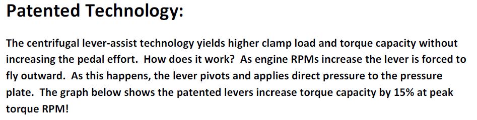
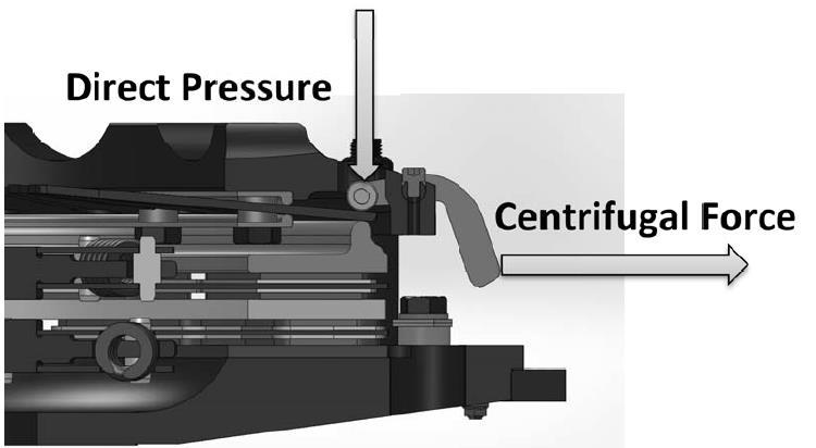
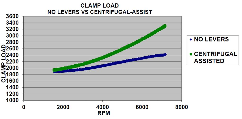
1 DRAGON CLAW SHELBY 26 SPLINE *This Kit Requires a Min. 1 ⅝ in. Working Input Shaft Splines. *Professional Installation recommended *Power/Air tools NOT advised 1. Remove transmission assembly per shop manual. (Inspect input shaft splines for damage or burring.) 2. Remove existing clutch and flywheel assembly. 3. Remove and install new pilot bearing (17). 4. Install new flywheel (1). Reinstall the factory flywheel bolts and torque them per shop manual. (Caution: Overtightening of flywheel bolts may result in crankshaft damage and oil leaks at the rear main seal.) 5. Install inner clutch disc (5) and floater (6). Install with sprung hub toward the flywheel or markings floater side toward the floater. Use supplied alignment tool (17) to align clutch disc and keep it centered. Attach floater straps (7) with locking nuts (8) to attached floater studs (3) with floater stands (4). Torque bolts to 25 ft-lbs. (Caution: Double check strap alignment before torquing.) 6. Install flywheel stands (10). Install outer disc (9) and cover assembly (11). Outer disc hub should be outward facing away from the crank toward the transmission or markings floater side toward the floater and trans side toward transmission. Carefully align flywheel studs to cover through holes. (Flywheel studs are clocked to allow assembly in correct position only.) Tighten 12-point 3/8 flange nuts (12) to 35 ft-lbs using a star pattern to draw cover down as evenly as possible. 7. On the stock Shelby GT 500, it will be necessary to replace release bearing and add shims behind the clutch slave and release bearing assembly. Add supplied shims (16). Install the new bearing using supplied (longer) bearing bolts (13) that replace the short stock bearing bolts. Torque per shop manual. 8. Reinstall transmission assembly taking caution not to hang transmission on the clutch disc or forcing splines into clutch disc. It is also recommended to put transmission in gear before installation. This will aid in the spline alignment by being able to turn the input shaft with the output shaft, or by slightly rocking the transmission back and forth. 9. Fully bleed clutch system. This can be accomplished by working the pedal as many as 50 or more times until the pedal feels pressure in full stroke. Product Insert # 199R11066 Part Number
2

3 PARTS LIST # Description Qty # Description Qty. 1 Flywheel 1 10 Outer Disc 1 2 Flywheel Studs 6 11 Cover/Diaphragm/Pressure Plate Assembly 1 3 Inner Disc Point 3/8 Flange Nuts 6 4 Flywheel Stands 6 13 Set Screws 2 5 Floater Straps 3 14 Alignment Tool 1 6 Floater 1 15 Release Bearing Bolts 2 7 Floater Studs 3 16 Pilot Bearing 1 8 Floater Stands 3 17 Flywheel Bolts 8 9 Locking Nut 3 18 Shims TBD* *Number of shims to be determined by application

4 BEARING SETUP TOOL
5 BEARING SETUP TOOL
6 HAYS LIMITED WARRANTY Due to the intended use of this product, warranty is limited to 90 days from the date of initial retail purchase. The product shall be free of defects in material and workmanship. Friction materials in this product are excluded. No warranty is offered for durability or specific performance because this is a consumable item. Hays is not responsible for the failure of mating components and/or other components of the driveline. Improper installation or improper application voids any warranty. If slippage occurs after installation stop use immediately and contact customer support. All products must be sent back to place of purchase for evaluation for warranty. Clutch problems are frequently attributed to adjustment and/or release system malfunction. *Before removal of the product for possible warranty, please refer to shop manual on operation and adjustment of the release system or proper release. The following list is common issues that are not covered under warranty. Worn Diaphragm fingers Hot spots on friction surfaces Lubricant on friction surfaces Damaged or worn friction material Damaged or broken disc hub and/or carrier Broken hub springs Worn bearing face Broken bearing seal Hays Technical Support Product Insert # 199R11066 Part Number
DRAGON CLAW PRE 86 BIG BLOCK CHEVY 10 SPLINE
 DRAGON CLAW PRE 86 BIG BLOCK CHEVY 10 SPLINE *This Kit Requires a Min. 1 ⅝ in. Working Input Shaft Splines. *Professional Installation recommended *Power/Air tools NOT advised 1. Inspect input shaft splines
Tech Note Truck 14 & 15.5 Twin Plate Cast Iron Type Installation Guidelines
 1. (14 & 15.5 ) Check condition of the flywheel. Grind to resurface or replace flywheel. Surface MUST BE machined or premature clutch failure can occur. Flywheel depth must be 2.938 (74.62mm) for 14 (350mm)
SACHS Clutches The Intelligent Choice for the Long Haul
 SACHS Clutches The Intelligent Choice for the Long Haul Twin XTend Clutch Installation Objectives: Identification Operation Tools Installation Troubleshooting Identification 15.5 Self Adjusting Clutch
CLUTCH 6-1 CLUTCH CONTENTS
 TJ CLUTCH 6-1 CLUTCH CONTENTS page GENERAL INFORMATION CLUTCH COMPONENTS... 1 INSTALLATION METHODS AND PARTS USAGE... 1 DESCRIPTION AND OPERATION CLUTCH OPERATION... 1 DIAGNOSIS AND TESTING DIAGNOSTIC
Performance Catalog. For Street Car and Diesel Pickup Applications
 Performance Catalog For Street Car and Diesel Pickup Applications ACE MANUFACTURING AND PARTS COMPANY A BRIEF HISTORY: Ace has been in the heavy duty clutch business since 1967. Starting as a pressure
Self-Adjust Clutch Installation Guide
 Self-Adjust Clutch Installation Guide 0 STOP! READ CAREFULLY BEFORE INSTALLING CLUTCH This clutch must be installed by a qualified installer. Improper installation or failure to replace or resurface the
ENGINE CLUTCH CONTENTS OF THIS SECTION
 ENGINE CLUTCH 6C-l ENGINE CLUTCH CONTENTS OF THIS SECTION SUBJECT General Description Periodic Service Adjustments on Car Removal of Clutch Inspection of Clutch Parts Installation of Clutch Specifications
Clutch Installation Guide
 Clutch Installation Guide 0 STOP! READ CAREFULLY BEFORE INSTALLING CLUTCH This clutch must be installed by a qualified installer. Improper installation or failure to replace or resurface the flywheel,
Clutches for Automobiles and Light Trucks
 Clutches for Automobiles and Light Trucks What does the Clutch do? Connects the engine torque to transmission when ENGAGED Unhooks engine from transmission when DISENGAGED Where is the driver s foot when
Clutch Installation Guidelines Follow Service Manual Instructions For Step-By- Step Procedures
 9700063 Revision 12/20/10 Clutch Installation Guidelines Follow Service Manual Instructions For Step-By- Step Procedures FAILURE TO FOLLOW PROPER INSTALLATION OR BREAK-IN PROCEDURES WILL VOID ANY WARRANTY
Clutch Kit Install Guide
 Jack up and support the car on jack stands Remove the exhaust system (some models) Remove the driveshaft (rear wheel drive) Remove CV axle (front wheel drive) Manual transmission removal Clutch Kit Install
Troubleshooting. Pull Type Clutches - Poor Release
 Troubleshooting Pull Type Clutches - Poor Release Complaint Possible Causes Corrective Action Poor Release Intermediate plate sticking on drive lugs due to cocked drive pins (AS and EP 1402 only) (see
page CLUTCH DIAGNOSIS 2
 6-1 CONTENTS page DIAGNOSIS 2 COMPONENTS MECHANICAL COMPONENTS The clutch mechanism in A D models with a gas or diesel engine consists of a single, dry-type clutch disc and a diaphragm style clutch cover.
Straight-Bore Clutch LSCC-32, 44, 54
 Straight-Bore Clutch LSCC-32, 44, 54 1 In accordance with Nexen s established policy of constant product improvement, the specifications contained in this manual are subject to change without notice. Technical
CLUTCH 6-1 CLUTCH CONTENTS
 Z CLUTCH 6-1 CLUTCH CONTENTS page page CLUTCH DIAGNOSIS... 2 CLUTCH SERVICE... 9 CLUTCH COMPONENTS MECHANICAL COMPONENTS The clutch mechanism in Grand Cherokee models with manual transmission consists
1992 Clutch. Eclipse, Expo/Expo LRV, Galant, Mirage, Precis, 3000GT
 Article Text ARTICLE BEGINNING 1992 Clutch Eclipse, Expo/Expo LRV, Galant, Mirage, Precis, 3000GT DESCRIPTION All clutches are single disc type. Pressure plate assembly uses a diaphragm spring to engage
South Bend Duramax DD
 South Bend Duramax DD Installation Instructions Torque specifications: Flywheel to crank 140-150 ft. lbs. Pressure plate to flywheel is 45 ft. lbs. Unbolt pressure plate from flywheel in a star pattern
Transmission Overhaul Procedures-Bench Service
 How to Assemble the Lower Reverse Idler Gear Assembly Special Instructions In 1996 Eaton changed the reverse idler system design. In the nut design, the reverse idler bearing was lubricated through a hole
HAYS HYDRAULIC RELEASE BEARING INSTALLATION INSTRUCTIONS
 HAYS HYDRAULIC RELEASE BEARING INSTALLATION INSTRUCTIONS PRELIMINARY INSTALLATION NOTES IMPORTANT! DO NOT RETURN THIS PRODUCT TO YOUR DISTRIBUTOR. If you have questions, please review additional information
1989 Ford Truck F 250 4WD Pickup V L DSL
 1989 Ford Truck F 250 4WD Pickup V8-445 7.3L DSL - M/T - Clutch Fluid Leaks/Incomplete Release Page 1 1989 Ford Truck F 250 4WD Pickup V8-445 7.3L DSL Top - Vehicle Transmission and Drivetrain. Clutch..
Clutch cover Type Diaphragm spring strap. Clutch pedal Type Suspended type. Maximum operating travel
 000000 043 1. SPECIFICATION Operating type Description Hydraulic type Specification Clutch cover Type Diaphragm spring strap Adjusting type Clutch pedal Type Suspended type Max. operating travel Pedal
CLUTCH - HIGH EFFORT - DASH CRACKED IN CLUTCH MASTER CYLINDER AREA-VEHICLES BUILT BEFORE 6/15/90
 Page 1 of 17 HIGH CLUTCH EFFORT/CLUTCH FLUID LEAK - CRACKED MOUNT TECHNICAL SERVICE BULLETIN Reference Number(s): 90-16-7, Date of Issue: August 1, 1990 Related Ref Number(s): 90-16-7 ARTICLE BEGINNING
Failure Diagnosis. The LuK guide to troubleshooting clutch system failures and malfunctions on agricultural vehicles
 Failure Diagnosis The LuK guide to troubleshooting clutch system failures and malfunctions on agricultural vehicles Contents Page Failure diagnosis / causes of failures Clutch fault diagnosis What is clutch
Through-Shaft Clutch-Brake LSCB-32HT, LSCB-32HT, LSCB-44, LSCB-44HT, LSCB-54HT FORM NO. L D-0606 MEX (55) QRO (442)
 QRO (442)") Through-Shaft Clutch-Brake LSCB-HT, LSCB-HT, LSCB-, LSCB-HT, LSCB-5HT In accordance with Nexen s established policy of constant product improvement, the specifications contained in this manual are subject
Through-Shaft Clutch-Brake LSCB-HT, LSCB-HT, LSCB-, LSCB-HT, LSCB-5HT In accordance with Nexen s established policy of constant product improvement, the specifications contained in this manual are subject
DYNATRAC PRODUCTS V5.3
 DYNATRAC PRODUCTS V5.3 2000-2008 Dodge Hub Kit Stage 1 4x4, Front Axle Free Spin Conversion Kit Note: This Kit is not Approved for 2007 & up 3500 Cab and Chassis Trucks Due to a Larger U-Joint (If U-Joint
Inspect the truck and, if necessary, use the following service procedure to install a reinforcement kit.
 1990 Ford Truck F 350 4WD Pickup V8-7.3L DSL Copyright 2007, ALLDATA 9.90 Page 1 Technical Service Bulletin # 90167 Date: 900801 M/T - Clutch Fluid Leaks/Incomplete Release Article No. 90-16-7 ^ CRACKS
CONCEPT 10.5 DUAL DISC INSTALLATION INSTRUCTIONS
 CONCEPT 10.5 DUAL DISC INSTALLATION INSTRUCTIONS Congratulations on your purchase of the RAM Concept 10.5 Dual disc clutch system. Please completely read and carefully follow the setup instructions, and
CROWERGLIDE AUTOMATIC CLUTCH Instruction Manual
 CROWERGLIDE AUTOMATIC CLUTCH Instruction Manual Crower Cams & Equipment Co., Inc 6180 Business Center Court San Diego, CA. 92154 Phone: 619.661.6477 ext. 148 Fax: 619.690.7846 www.crower.com TABLE OF CONTENTS
WARNING: Only perform this installation if you are experienced, fully equipped mechanic.
 DYNATRAC V3.2 2005-Present Ford Super Duty 250/350-4x4, Front Axle, Free Spin Conversion Kit Some of the less common tools, which will be required: 6 point Spanner socket (OTC #7090-A or equivalent). These
Borg & Beck Clutch Information
 Borg & Beck Clutch Information After the clutch is bolted to the flywheel, under no circumstance should the release lever, or the release lever plate if equipped, be pulled away from the flywheel against
L&T MANUFACTURING, INC.
 100-9 Aluminum Cover Assembly 76.50 100-10 Aluminum Cover 64.75 100-11 Cover Gasket (Rubber) 2.85 100-11-1 Cover Gasket (Paper) 3.00 100-12-1 Lever Weight 1 Disc 1.60 100-12-3 Lever Weight 3 Disc 1.60
ATASA 5 th Study Guide Chapter 36 Pages Clutches 74 Points. Clutches. Be Certain to Read the Summary
 ATASA 5 th Study Guide Chapter 36 Pages 1071 1091 74 Points Be Certain to Read the Summary 1. The provides a mechanical coupling between the engine s & the transmission s shaft. The clutch allows the engine
INSTALLATION INSTRUCTIONS MKIV Toyota Supra Manual Rack Conversion
 INSTALLATION INSTRUCTIONS MKIV Toyota Supra Manual Rack Conversion 1 Removal of Stock Rack 1.1 With your steering wheel centered, remove the pinch bolt from the factory intermediate shaft. This is located
 www.clubsuprafrance.com CLUTCH 1996 Toyota Supra 1995-96 Clutch Supra DESCRIPTION The single, dry-type disc clutch uses a hydraulicallyoperated master cylinder with a clutch release cylinder mounted on
1. General GENERAL CL-2
 SYSTEM GENERAL 1. General The clutch is of a dry, single plate type with a diaphragm spring. The clutch is a push type clutch. When the pedal is depressed, the release bearing will press the center of
Service Manual. LL30002 Rev. 7/03. HEAVY DUTY PUSH/PULL TYPE CLUTCHES
 Service Manual LL30002 Rev. 7/03 HEAVY DUTY PUSH/PULL TYPE CLUTCHES www.haldex.com Table of Contents Section One - Push Type Clutches Clutch Assembly Cutaway Detail............................1 Clutch
(877) MON-FRI 7AM-5PM PST OR WEBSITE: ReadyLIFT.COM **Please retain this document in your vehicle at all times**
 MON-FRI 7AM-5PM PST OR WEBSITE: ReadyLIFT.COM **Please retain this document in your vehicle at all times**") IF YOUR ReadyLIFT PRODUCT IS MISSING A OR HAS A DAMAGED PART, PLEASE CONTACT CUSTOMER SERVICE DIRECTLY. For warranty issues please return to the place of installation and contact ReadyLIFT. A NEW REPLACEMENT
IF YOUR ReadyLIFT PRODUCT IS MISSING A OR HAS A DAMAGED PART, PLEASE CONTACT CUSTOMER SERVICE DIRECTLY. For warranty issues please return to the place of installation and contact ReadyLIFT. A NEW REPLACEMENT
Crankshaft Seal, Replacement (Rear) This information covers service procedures for replacing the rear crankshaft seal on the Volvo D16F engine.
 This information covers service procedures for replacing the rear crankshaft seal on the Volvo D16F engine.") Volvo Trucks North America Greensboro, NC USA Crankshaft Seal, Replacement (Rear) DService Bulletin Trucks Date Group No. Page 3.2007 216 79 1(6) Crankshaft Seal Replacement (Rear) D16F W2005773 This information
Volvo Trucks North America Greensboro, NC USA Crankshaft Seal, Replacement (Rear) DService Bulletin Trucks Date Group No. Page 3.2007 216 79 1(6) Crankshaft Seal Replacement (Rear) D16F W2005773 This information
2006 Hyundai Tiburon GT
 Fig. 5: Identifying Clutch Cover & Disc Component With Torque Specifications REMOVAL 1. Drain the clutch fluid and transaxle gear oil. 2. Remove the transaxle assembly. 3. Insert the special tool (09411-25000)
New tool for installing clutch driven plate and pressure plate.
 1(5) New tool for installing clutch driven plate and pressure plate. Special tools: 999 5662-5, 999 5663-3 It is very important to center the clutch driven plate and pressure plate is very important when
ASSEMBLY INSTRUCTIONS FOR DYNALITE DRAG RACE FRONT HUB KIT WITH DIAMETER SOLID ROTOR PINTO / MUSTANG II
 ASSEMBLY INSTRUCTIONS FOR DYNALITE DRAG RACE FRONT HUB KIT WITH 0.75 DIAMETER SOLID ROTOR 97-978 PINTO / MUSTANG II (FIVE LUG CONFIGURATION ONLY)* PART NUMBER GROUP 0-03-B DISC BRAKES SHOULD ONLY BE INSTALLED
DIM Drive Train Systems
 2014 NATEF JOB TASKS COMPLETION REQUIREMENT: P1-95% P2-70% P3-25% Student Name: DETAILED COURSE CONTENT II. DRIVE TRAIN A. CLUTCH -- The student will be able to: P1 P2 P3 Level Date 1. Identify causes
ASSEMBLY INSTRUCTIONS FOR PRO-MATRIX OE UPGRADE PAD AND ROTOR KIT REAR, WITH DIAMETER VENTED ROTOR CHEVROLET C-4 CORVETTE
 ASSEMBLY INSTRUCTIONS FOR PRO-MATRIX OE UPGRADE PAD AND ROTOR KIT REAR, WITH 1.00 DIAMETER VENTED ROTOR 1988-1996 CHEVROLET C-4 CORVETTE PART NUMBER GROUP 140-8314 DISC BRAKES SHOULD ONLY BE INSTALLED
CLUTCH CONTENTS SERVICE DIAGNOSIS. (a) Worn or damaged disc assembly. (b) Grease or oil on disc facings. (c) Improperly adjusted cover assembly.
 Worn or damaged disc assembly. (b) Grease or oil on disc facings. (c) Improperly adjusted cover assembly.") CLUTCH CONTENTS -GROUP 6 Page CLUTCH HOUSING ALIGNMENT... 6 CLUTCH PEDAL FREE PLAY 1 CLUTCH RELEASE BEARING 5 CLUTCH RELEASE FORK... 5 CLUTCH SERVICING 2 PILOT BUSHING CRANKSHAFT TO TRANSMISSION DRIVE
CLUTCH CONTENTS -GROUP 6 Page CLUTCH HOUSING ALIGNMENT... 6 CLUTCH PEDAL FREE PLAY 1 CLUTCH RELEASE BEARING 5 CLUTCH RELEASE FORK... 5 CLUTCH SERVICING 2 PILOT BUSHING CRANKSHAFT TO TRANSMISSION DRIVE
AT Clutch Major Service Sizes 25, 55, 115
 P-1404 819-0324 AT Clutch Major Service Sizes 25, 55, 115 Installation Instructions Contents Introduction............................ 2 Warranty....................... back cover Failure to follow these
Elgin Hydraulic Clutch-Brake ECB-240, Product Number FORM NO. L F FORM NO. L F-0704
 Elgin Hydraulic Clutch-Brake ECB-20, Product Number 96225 FORM NO. L-20283-F-070 1 FORM NO. L-20283-F-070 In accordance with Nexen s established policy of constant product improvement, the specifications
INSTALLATION INSTRUCTIONS. FD3S RX7 Manual Rack Conversion
 INSTALLATION INSTRUCTIONS FD3S RX7 Manual Rack Conversion 1 Removal of Stock Rack 1.1 With your steering wheel centered, remove the pinch bolt from the factory intermediate shaft lower knuckle. If you
This file is available for free download at
 This file is available for free download at http://www.iluvmyrx7.com This file is fully text-searchable select Edit and Find and type in what you re looking for. This file is intended more for online viewing
WRANGLER, CHEROKEE AND COMANCHE, FRONT AXLE WHEEL HUB CONVERSION KIT
 WRANGLER, CHEROKEE AND COMANCHE, FRONT AXLE WHEEL HUB CONVERSION KIT -YA WU-07 5 x 4.5 -YA WU-08 5 x 5.5 *THIS KIT IS NOT INTENDED FOR VEHICLES WITH ABS AND YA WU-08 WILL CHANGE BOLT PATTERN TO 5 ON 5.5*
Clutch Diagnosis - Causes of Failure
 Clutch Diagnosis - Causes of Failure Guide Tube wear, Spline wear, Mainshaft Bearing wear Worn Flywheel Bearing, ridged or heat damaged Flywheel surface Worn/siezed Release Arm pivots, friction lining
CARBONETIC Carbon Clutch operating instructions
 ACROSS USA INC www.carbonetic.net TEL:310-635-3555 CARBONETIC Carbon Clutch operating instructions Thank you very much for your purchase of the CARBONETIC carbon clutch. Please read these instructions
Clutch System Troubleshooting Guide-Service Tips
 DESCRIPTION AND OPERATION Clutch System The purpose of the clutch is to connect and disconnect a manually operated transmission and the remainder of the powertrain system from the engine. This permits
1994 Mazda MX-5 Miata. CLUTCH 1994 Clutch
 CLUTCH 1994 Clutch DESCRIPTION Miata uses a hydraulically operated clutch. HYDRAULIC SYSTEM BLEEDING 1. Remove bleeder screw cap, located at clutch release cylinder. Install vinyl hose onto bleeder screw.
ASSEMBLY INSTRUCTIONS
 ASSEMBLY INSTRUCTIONS FOR FORGED SUPERLITE BIG BRAKE FRONT HUB KIT WITH 3.00 DIAMETER VENTED ROTOR 968-969 FORD MUSTANG (DISC BRAKE SPINDLE ONLY) PART NUMBER GROUP 0-950 WARNING INSTALLATION OF THIS KIT
Contents c mm Ø Cerametallic & Organic Drive Plate Hub Spline Details H e l i x
 Contents Part Number Legend... 2 The HELIX Racing Clutch Range... 4 Clutch Terminology... 5 Clutch Fitting & Flywheels... 6 Release Bearings... 7 Concentric Slave Cylinder Release Bearings... 8 Clutch
Geared Drives 200Z PSRU Zero Offset Gearbox with Centrifugal Clutch Assembly
 Instructions for Removing and replacing Gen X Gearbox with Geared Drives 200Z Prior to your gear box arriving: Using a strap or chain and an engine hoist to hold your engine up in the mount, remove your
RZR 800 SLP Clutch Kit Installation Instructions
 RZR 800 SLP Clutch Kit Installation Instructions Clutch Removal A-1. Remove seats and seat retaining bar from RZR. (Rear seats and seat retaining bar in RZR-4) Illustration #1 A-2. Loosen hose clamp located
DRIVE AXLE Nissan 240SX DESCRIPTION & OPERATION AXLE RATIO & IDENTIFICATION AXLE SHAFT & BEARING R & I DRIVE SHAFT R & I
 DRIVE AXLE 1990 Nissan 240SX 1990 DRIVE AXLES Rear Axle - R200 240SX, 300ZX DESCRIPTION & OPERATION The axle assembly is a hypoid type gear with integral carrier housing. The pinion bearing preload adjustment
Advanced Technology Tension Clutches
 P-220 819-0339 Advanced Technology Tension Clutches Installation Instructions Contents Installation................................. 2 Clutch Repair On the Shaft.................. 4 Clutch Service Major.......................
ASSEMBLY INSTRUCTIONS FOR PART NUMBER GROUP
 ASSEMBLY INSTRUCTIONS FOR DYNAPRO 6 BIG BRAKE FRONT HAT KIT, 1.19 DIAMETER VENTED ROTOR 1990-005 ACURA/CIVIC ( LUG) 000-003 CIVIC SI ( LUG) 007 - PRESENT HONDA FIT FOR FACTORY 6 mm DISC SPINDLE PART NUMBER
CL - Clutch Replacement
 2003 3.2CL - Clutch Replacement Special Tools Required Pressure plate compressor 07AAE-P8EA000 Clutch alignment shaft 07AAF-P8EA000 Pressure plate compressor adapter 07AAK-P8EA000 Ring gear holder 07LAB-PV00100
370 and 390 Mono 6 Brake Kit Installation Guide
 370 and 390 Mono 6 Brake Kit Installation Guide Application Guide Description C7 A6 / A7 390mm Mono6 Brake Kit B8 A4/S4/A5/S5/Q5 390mm Mono 6 Brake Kit C7 A6 / A7 370mm Mono 6 Brake Kit B8 A4/S4/A5/S5/Q5
CLUTCH Nissan 240SX DESCRIPTION PEDAL HEIGHT & FREE PLAY ADJUST CLUTCH ASSEMBLY R & I Clutch. Pathfinder, Pickup, 240SX, 300ZX
 CLUTCH 1990 Nissan 240SX 1990 Clutch Pathfinder, Pickup, 240SX, 300ZX DESCRIPTION Clutch is of dry, single disc type, with a diaphragm spring type pressure plate. Clutch release bearing is prelubricated.
Detroit Speed, Inc. Detroit Speed C7 Rear Full Floater Kit P/N: , , , , &
 Detroit Speed, Inc. Detroit Speed C7 Rear Full Floater Kit P/N: 070512, 070607, 070616, 070626, 070636 & 070649 Thank you for purchasing the Detroit Speed Inc., C7 Rear Full Floater Kit. The Detroit Speed
DYNA EVO & T.C. MODELS 91-05
 ASSEMBLY DIAGRAM AND ASSEMBLY REFERENCE ULTIMA OLD SCHOOL 2 BELT DRIVE UNITS DYNA EVO & T.C. MODELS 91-05 Part # 58-900 2 BELT DRIVE ASSEMBLY REV 10-22-14 ASSEMBLY DIAGRAM AND ASSEMBLY REFERENCE ULTIMA
GROUP 6 CLUTCH CONTENTS SPECIFICATIONS
 GROUP 6 CLUTCH CONTENTS Page CLUTCH 6-1 Specifications.... 1 Transmission Main Drive Pinion Pilot Bushing... 5 Special Tools. 1 Clutch Release Bearing 6 Torque Reference 1 Torque Shaft and Bearings...
M-2300-M Mustang GT Rear Disc Brake Bracket Kit INSTALLATION INSTRUCTIONS
 Please contact the Tech Line for the most current instruction information (800) 367-3788!!! PLEASE READ THE FOLLOWING INSTRUCTIONS CAREFULLY PRIOR TO INSTALLATION!!! INTRODUCTION: This kit allows for the
ALLISON 1000 SIGNATURE SERIES
 ALLISON 1000 SIGNATURE SERIES 2001-2010 DURAMAX GPZ 1 FLUID CAPACITY INSTALLATION In our RevMax performance transmission we require you to use DEXRON 3 fluid and are shipped empty due to the regulations
ATS metal clutch (twin / triple) instruction manual for Nissan 350Z w/ HR motor 12 pages
 instruction manual for Nissan 350Z w/ HR motor 12 pages") ATS metal clutch (twin / triple) instruction manual for Nissan 350Z w/ HR motor 12 pages This instruction is provided by Performance Partners Intl 1 ATS Clutch operating instructions Thank you very much
ATS metal clutch (twin / triple) instruction manual for Nissan 350Z w/ HR motor 12 pages This instruction is provided by Performance Partners Intl 1 ATS Clutch operating instructions Thank you very much
Clutch, Pressure Plate, And Pilot Bearing Replacement
 Page 1 of 6 2008 Chevrolet Aveo : Transmissions > Clutch > Repair Instructions > Clutch, Pressure Plate, And Pilot Bearing Replacement Clutch, Pressure Plate, And Pilot Bearing Replacement CLUTCH, PRESSURE
INSTALLATION INSTRUCTIONS
 11485 YEARS: 2015-CURRENT Safety glasses should be worn at all times while installing this product. INSTALLATION INSTRUCTIONS MODEL: C300 MAKE: MERCEDES STYLE: SEDAN WARNING: NEVER EXCEED YOUR VEHICLE
ASSEMBLY INSTRUCTIONS
 ASSEMBLY INSTRUCTIONS FOR DYNALITE PRO SERIES FRONT HUB KIT WITH.75 DIAMETER VENTED ROTOR 970-973 FORD MUSTANG (DRUM / DISC SPINDLE) PART NUMBER GROUP 0-905 WARNING INSTALLATION OF THIS KIT SHOULD ONLY
USER MANUAL. NEMA 48C Flange Mounted, Enclosed, Clutch Brake. FMCBE Model 500 FORM NO. L A (i)
") USER MANUAL NEMA 48C Flange Mounted, Enclosed, Clutch Brake FMCBE Model 500 (i) In accordance with Nexen s established policy of constant product improvement, the specifications contained in this manual
USER MANUAL NEMA 48C Flange Mounted, Enclosed, Clutch Brake FMCBE Model 500 (i) In accordance with Nexen s established policy of constant product improvement, the specifications contained in this manual
DYNATRAC V6.0. WARNING: Only perform this installation if you are experienced, fully equipped mechanic.
 DYNATRAC V6.0 1999-2004 Ford Super Duty 250/550-4x4, Front Axle, Free Spin Conversion Kit Some of the less common tools, which will be required: 6 point Spanner socket (OTC #7090-A or equivalent) OR 4
Primary Brake Spline Drive Armature PB-825, PB-1000, PB-1225, PB-1525
 Primary Brake Spline Drive Armature PB-825, PB-1000, PB-1225, PB-1525 P-209-WE 819-0517 Installation Instructions Contents Installation Instructions PB-825 PB-1000 PB-1225 PB-1525... 3 Coil Data... 5 Burnishing
Housing (Front) - Remove
 - Remove") SENR9978-01 63 1. Lift the assembly (3) of the idler gear and the hub over the housing for the crankshaft front seal (2) and insert the hub into the recess in the cylinder block. Refer to illustration
SENR9978-01 63 1. Lift the assembly (3) of the idler gear and the hub over the housing for the crankshaft front seal (2) and insert the hub into the recess in the cylinder block. Refer to illustration
BRAKE SYSTEM Nissan 240SX DESCRIPTION BRAKE BLEEDING * PLEASE READ FIRST * BLEEDING PROCEDURES ADJUSTMENTS BRAKE PEDAL HEIGHT SPECS TABLE
 BRAKE SYSTEM 1990 Nissan 240SX 1990 BRAKE SYSTEMS Nissan Disc & Drum Axxess, Maxima, Pathfinder, Pickup, Pulsar NX, Sentra, Stanza, 240SX, 300ZX DESCRIPTION All brake systems are hydraulically operated
ALL INFINITI; BRAKE NOISE/JUDDER/PEDAL FEEL DIAGNOSIS AND REPAIR
 Classification: Reference: Date: BR00-005e ITB00-024e August 8, 2007 ALL INFINITI; BRAKE NOISE/JUDDER/PEDAL FEEL DIAGNOSIS AND REPAIR This bulletin has been amended. The Applied Vehicles have been updated.
FCB-450, LCB-600, MCB-800
 AIR CHAMP PRODUCTS User Manual FCB-450, LCB-600, MCB-800 Clutch-Brakes (i) In accordance with Nexen s established policy of constant product improvement, the specifications contained in this manual are
GM 4T65E Installation Tips
 GM 4T65E Installation Tips WARNING: DO NOT operate vehicle without installing a new transmission oil cooler. We recommend installing a Hayden 1403 or 1404. Bypass the radiator and install the new cooler.
CLUTCH 6-1 CLUTCH TABLE OF CONTENTS
 PL CLUTCH 6-1 CLUTCH TABLE OF CONTENTS page DESCRIPTION AND OPERATION MODULAR CLUTCH ASSEMBLY....1 CLUTCH CABLE...1 CLUTCH INTERLOCK/UPSTOP SWITCH....1 DIAGNOSIS AND TESTING CLUTCH SYSTEM DIAGNOSIS...2
NV3550 TO FORD BRONCO
 NV3550 TO 1966-77 FORD BRONCO KIT CONSISTS OF: No. 1. 2. 3. 4. 5. Qty 1 1 Kit 1 Kit 1 Kit 1 Kit Part No. 26-3550 50-9920 712544 716000 716099 Description NV3550 TRANSMISSION TRANSFER CASE ADAPTER & TC
Clutch Clut Fundament Fundamen als t Chapter 69
 Clutch Fundamentals Chapter 69 Objectives Describe the basic clutch parts Explain the operation of the clutch Compare differences in clutch hdesign Describe the different methods of releasing the clutch
DYNA EVO & T.C. MODELS 91-05
 ASSEMBLY DIAGRAM AND ASSEMBLY REFERENCE ULTIMA OLD SCHOOL 2 BELT DRIVE UNITS DYNA EVO & T.C. MODELS 91-05 Part # 58-900 2 BELT DRIVE ASSEMBLY REV 1-20-10 ASSEMBLY DIAGRAM AND ASSEMBLY REFERENCE ULTIMA
MINI COOPER COUNTRYMAN
 2/19/2013 GROSS LOAD CAPACITY WHEN USED AS A WEIGHT CARRYING HITCH: 2000 LBS. TRAILER WEIGHT & 200 LBS. TONGUE WEIGHT. ***DO NOT EXCEED VEHICLE MANUFACTURER'S RECOMMENDED TOWING CAPACITY.*** WARNING: ALL
SECTION D REAR SUSPENSION. Section Description Page D.1. REMOVING AND REFITTING A REAR SUSPENSION UNIT 5
 SECTION D REAR SUSPENSION Section Description Page D.1. REMOVING AND REFITTING A REAR SUSPENSION UNIT 5 D.2. REMOVING AND REFITTING THE COMPONENTS OF THE REAR SUSPENSION 8 D.3. CHECKING AND OVERHAULING
ALL NISSAN; BRAKE NOISE/JUDDER/PEDAL FEEL DIAGNOSIS AND REPAIR
 Classification: Reference: Date: BR00-004e NTB00-033e July 23, 2013 ALL NISSAN; BRAKE NOISE/JUDDER/PEDAL FEEL DIAGNOSIS AND REPAIR This bulletin has been amended to include vehicles built up to the publication
Module 1: Introduction to Drive Trains
 Introduction ÂÂ Basic Components of a Drive Train Operation of a Drive Train Working Applications Types of Drives Types of Gears Formula for Calculating Gear Ratio Determining Gear Rotation Introduction
Maintenance Instructions
 General Note These instructions contain information common to more than one model of Bevel Gear Drive. To simplify reading, similar models have been grouped as follows: GROUP 1 Models 11, 0, 1,, (illustrated),,
13093 INSTALLATION INSTRUCTIONS
 109 INSTALLATION INSTRUCTIONS Safety glasses should be worn at all times while installing this product. YEARS: 2011-PRESENT MAKE: DODGE / CHRYSLER MODEL: CHARGER / 00C / 00S STYLE: SEDAN / COUPE WARNING:
RZR 570 SLP Clutch Kit Installation Instructions
 RZR 570 SLP Clutch Kit Installation Instructions Clutch Removal Illustration #1 A-1. Jack up the rear of the RZR until the driver side rear suspension is at full droop and the rear tire is off the ground.
SECTION 3A FRONT DRIVE AXLE TABLE OF CONTENTS SPECIFICATIONS GENERAL SPECIFICATIONS. Description Drive Shaft Type. CV Joint Axle Housing Type
 SECTION 3A FRONT DRIVE AXLE TABLE OF CONTENTS Specifications........................ 3A-1 General Specifications.................. 3A-1 Fastener Tightening Specifications......... 3A-2 Component Locator...................
Installation Instructions / 2301 / 2302 / 2303 IMPORTANT NOTE: - Phone: (800)
") IMPORTANT NOTE: Stock measurements of the vehicle cannot exceed 22 when measured from the center of the wheel to the fender line above in the front. If so, then the preload spacer cannot be used as the
IMPORTANT NOTE: Stock measurements of the vehicle cannot exceed 22 when measured from the center of the wheel to the fender line above in the front. If so, then the preload spacer cannot be used as the
11333 INSTALLATION INSTRUCTIONS
 11333 INSTALLATION INSTRUCTIONS Safety glasses should be worn at all times while installing this product. YEARS: 2011-PRESENT MAKE: MINI COOPER MODEL: COUNTRYMAN STYLE: SEDAN WARNING: NEVER EXCEED YOUR
Edition October 2014 Part No
 Edition 1.3 - October 2014 Part No. 8999076 1 Contents Ordering Your Parts... 3 Centre Section - S180025.70... 5 Wing Section - S180025.71/72...7 Centre Axle - S180025.110... 9 Wing Axle - S180025.111...10
*THIS KIT IS NOT INTENDED FOR VEHICLES WITH ABS*
 *THIS KIT IS NOT INTENDED FOR VEHICLES WITH ABS* Notes: New full-cast rotors from 1990 or newer Wrangler must be used with this kit, this rotor (ITT #65225 or equivalent) has a.25 thick mounting flange.
Instruction set # 7068 Cognito Motorsports, Inc. Upper Control Arm Leveling Kit for GM 8-Lug #UCAK (Boxed Style)
") Cognito Motorsports, Inc. Upper Control Arm Leveling Kit for 2001-2010 GM 8-Lug #UCAK100010 (Boxed Style) Introduction - These control arms will not affect the height of the truck, the height is determined
Cognito Motorsports, Inc. Upper Control Arm Leveling Kit for 2001-2010 GM 8-Lug #UCAK100010 (Boxed Style) Introduction - These control arms will not affect the height of the truck, the height is determined
Installation Instructions
 Preparing your vehicle to install your brake system upgrade 1. Rack the vehicle. 2. If you don t have a rack, then you must take extra safety precautions. 3. Choose a firmly packed and level ground to
LATERAL LIMITER KIT TORSION BAR KIT
 C42-429 C42-427 LATERAL LIMITER KIT Controls engine and transmission movement during hard acceleration or braking. With 4130 chromoly tubing and brackets, this kit is recommended when using motor plates.
ASSEMBLY INSTRUCTIONS FOR SCION xa, xb SUPERLITE 4 BIG BRAKE FRONT BRAKE KIT WITH DIAMETER VENTED ROTOR* BASE PART NUMBER
 ASSEMBLY INSTRUCTIONS FOR 00-006 SCION xa, xb SUPERLITE BIG BRAKE FRONT BRAKE KIT WITH 1.88 DIAMETER VENTED ROTOR* BASE PART NUMBER 10-8335 DISC BRAKES SHOULD ONLY BE INSTALLED BY SOMEONE EXPERIENCED AND